

Submitted:
05 July 2026
Posted:
06 July 2026
You are already at the latest version
Abstract
Optical microfibers are fabricated by pulling classical silica fibers until reaching diameters of a few micrometers or less. These devices are significantly exploited in many science and engineering fields, ranging from fundamental research to practical applications. Despite their many attractive advantages, a major technological challenge remains: heating caused by laser absorption from surface defects and contaminants. In the present study, we propose, for the first time to our knowledge, a novel method to measure the temperature evolution of laser self-heated microfibers in air at a wavelength of 1.48 µm. This method, simple and fast, enables us to investigate the influence of the diameters and lengths of the microfibers. We found that the temperature of the microfibers increases linearly with the power and measured a rise of 70°C for a 1 µm diameter and 20 mm length microfiber at a moderate power of 160 mW. A numerical model considering the microscale and the heat exchange with air is proposed and is adjusted with experimental data, providing values for the thermal transfer coefficient. By investigating power scaling, this work enables the prediction of temperature increases in self-heated microfibers in air, paving the way for new insights into the self-cleaning of microfiber-based devices and for optimized control of light propagation at high power levels.
Keywords:
tapered optical fiber
; silica microfiber
; laser self-heating
; temperature effect
1. Introduction
Optical micro or nanofiber (named OMF in the following), i.e., the homogeneous section of a stretched and tapered silica optical fiber (micro or sub micrometer diameter on length of up to more than 10 cm, see Figure 1) between two tapered transitions, has been presented a widespread use in science and engineering applications since more than thirty years as an elementary optical component easily integrated by its nature in an all-fibered network [1,2]. The expanding use of OMF is due to its physical properties. The optical modes guided by the OMF have large intensities due to their strong transverse confinement, present very low losses that can be below 0.002 dB/cm, far beyond other micro/nano waveguides [3]. The modes can also exhibit an evanescent part outside the OMF with a transverse spatial profile, thus an intensity, depending on the radius, which can be used to probe the external medium. Due to these intrinsic properties, OMF-based technologies address a large versatility of domains from fundamental to applications such as quantum information devices (trapped atoms for quantum light-matter interfaces [4,5], photon-pair generation [6]), nonlinear optics (supercontinuum generation [7], stimulated Raman [8,9] and Brillouin [10] scattering, Kerr effect [11]), remote sensor devices [12,13], detection (gas, liquid [14], bio-chemicals [15]), devices for coupling light into micro-photonic components [16,17] for the most active ones. All these previous studies demonstrate the strong mechanical resistance of an OMF to shocks, intensive uses and manipulations, their potential uses in vacuum, gas, liquids, and ability to different coatings [18]. However, despite all these attractive benefits, one technological lock of the OMF has been identified [19,20,21]. When a laser light is coupled into the OMF, it has been shown that the optical mode can be absorbed by surface pollution or defects. This surface absorption, even low, can lead to an increase of the temperature of the OMF, which can in turn induce optical instabilities. For instance, an increase of 50 °C of a silica OMF would induce an increase of its refractive index of . Such a modification can already affect modal phase-matching conditions in nonlinear optics for instance. Optical performances can also be degraded by this heating and the OMF can even be destroyed [22]. Most of the time, the solution is simply to change the damaged OMF. However, such a solution is on the one hand clearly not satisfying and on the other hand very constraining for applications where access to the OMF is difficult. Controlling these thermal effects would remove a technological barrier and enable a broader deployment of these highly promising components.
Only few works have studied laser self-induced temperature in OMFs and are all based on indirect temperature measurements. Pump/probe experiments in which the pump acted as the heating source have been used to measure the thermally induced optical path change of the OMF. Different configurations have been implemented, as a Fabry-Perot cavity formed by two Bragg gratings inserted on both sides of the OMF [19] or a balanced heterodyne detection [23]. These works are focused on OMFs used for cold atoms manipulation in ultra vacuum. In such environment the OMF can only be cooled through radiation, which is not efficient. Consequently, temperatures above 1000 K leading to the destruction of the OMF are measured for low input powers of a few tens of milliwatts. The first measurement of self-heating OMF in nitrogen environment has been demonstrated recently [24]. In this reference, a silica knot resonator made with the OMF is used and the resonance peak, depending on the temperature, is probed. The authors measured a temperature of almost 300 °C for an injected pump power of 7 W emitting at 1.5 µm in a nanofiber having a diameter of 410 nm. Despite their elegance, these methods are not direct and do not allow for simple and versatile measurements. For instance, it is difficult to change the OMF to evaluate the impact of one of its geometrical parameters such as the length or the diameter on the temperature variation. Moreover, these methods give only value of the temperature integrated on the OMF and its tapers and not on precise locations along the device.
In this work we propose an experimental method that enables us to measure the temperature increase of OMF under laser injection. This method presents several advantages: it is direct, nondestructive, very simple to implement and enables us to make spatially distributed measurements not only along the OMF part but also along both tapers. Indeed, we believe the temperature increase in the tapers may also be significant and may induce optical instabilities. Finally, many measurements can be performed on the same OMF and thanks to the simplicity of the technique, several geometric parameters of the device can be easily tested as well as different laser sources, opening the way to a large parametric study.
On the other side, modelling the laser self-induced temperature variations in an OMF is a challenging task, due to the unusual shape of OMFs associated with a micro scale dimension over several centimeters. Firstly, as the transverse dimension of the OMF is smaller than the thermal wavelength (, an OMF does not radiate as the black body [19]. Planck’s law cannot be simply used and the spectral emissivity, which at this scale strongly depends on the OMF radius, must be calculated. Secondly, the modelling of the heat exchange with the surrounding medium at this micrometer scale needs the knowledge of some fundamental physical quantities such as the absorption of light at the considered wavelength and the heat transfer coefficient, this later being not documented in the literature. Our numerical model is adjusted with the data we collected through our experimental method. This enables us to evaluate values of these two parameters which in turn gives a way to predict the evolution of the temperature in laser self-heated OMFs.
The article is organized as follows: in the section Materials and Methods, after a description of the experimental setup, we present the numerical model we have implemented. Then in the section Results, we present the measurements of the evolution of the temperature in silica OMF heated by a laser at the wavelength of 1.48 µm for three different OMF diameters (3 µm, 4 µm and 5 µm) and three different OMF lengths (20 mm, 33 mm and 38 mm The experimental results are then compared with the numerical model, and a discussion follows (section Discussion).
2. Materials and Methods
2.1. Experimental Part
The OMFs are pulled from standard single mode fiber used for telecommunications. The pulling rig is described in [8,9]. The principle is that a butane flame softens the fiber central part while two computer-controlled translation stages elongate it following the classical “pull and brush” technique [26] to create the OMF and its two tapers - named ‘the device’ in the following. A scheme of the device is shown in Figure 1. The pulling process is divided into cycles. Each cycle adds a small section to the taper while the diameter of the fiber cladding is reduced by a constant ratio to reach the OMF waist diameter at the end of the last cycle. This fabrication process, carried out in a class-5 cleanroom to avoid dust deposition, allows us to routinely produce OMFs with on-demand diameters as small as 200 nm and lengths of up to 8 cm, as well as light transmission larger of typically 90% over the full device [9].
The experimental setup is shown in Figure 2. After the fabrication, the input and output ends of the untapered fiber are spliced to two pigtails. The two unstreched parts on both sides of the tapers are held on two separate supports fixed on a rectangular plate with the help of two magnets, keeping the OMF and the tapers tight and suspended in air between the two supports. Then the device with its two pigtails is put on the experimental set-up on a motorized translation stage.
We used a continuous wave fibered Raman laser emitting at the wavelength of 1.48 µm a maximum power of 3 W. The fibered laser output is connected to the input pigtail of the device while the output pigtail is connected to a powermeter. The optical transmission of the device , where is the power coupled in the input pigtail and is the power collected at the output pigtail, is measured for each device and is typically around 80% to 90%. Considering that the tapers are symmetrical and are the main origins of the transmission losses, we estimate the power inside the OMF . A type K thermocouple with a diameter of 250 µm is used to measure the temperature at the surface of the device by contact. According to [24], heat diffuses in air over a distance on the order of 2 mm in the surrounding of the OMF. The thermocouple is therefore located within a temperature gradient that is larger than its own diameter. If we assume, as an approximation, a linear gradient, then the end of the thermocouple diametrically opposed to the one in contact with the OMF is at a temperature relatively close to that of the OMF. In other words, the temperature given by the thermocouple is very close to the true value and underestimated by only 1 to 2 °C. We firstly image the unstretched beginning of the left taper having a diameter of 125 µm on the CCD camera with a microscope objective (Mitutoyo, x20). As shown in Figure 2, top left image, we approach the tip of the thermocouple in the field of the CCD, putting its most sensitive part in contact with the fiber. We measure the local diameter of the fiber in the center of the image, record the temperature of the thermocouple and the output power after waiting a few tens of seconds for stabilization. The motorized translation stage on which the OMF is placed has a course of 15 cm, enabling us to scan the whole device without removing it from the support. We take the above-mentioned measurements every one millimeter by sliding the device over the thermocouple. The camera image also makes it possible to verify that the temperature is always measured at the same location on the thermocouple. For one OMF with its tapers, 30 to 50 measurements are taken along the device, which lasts about 30 minutes. We check that the output power does not vary under the contact of the thermocouple, ensuring that the temperature which is measured is the one of the fiber and not induced by a leak of light (see Figure 2, top right plot). Indeed, when the diameter reduces, the evanescent field of the guided mode might also induce an increase in the thermocouple temperature, disturbing the measurement. We measure that the thermocouple begins to heat when illuminated by a power of 5 mW. The fraction of the evanescent light being only 2% for an OMF diameter of 2.5 µm at a wavelength of 1.48 µm, we limited our measurements to OMF with diameters higher than 2.5 µm and coupled power of the light in the OMF to 160-200 mW.
2.2. Numerical Modelling
In this part, we describe the thermodynamical model we have implemented, based on [19]. This model was used for OMF in ultra vacuum and we adapted it to our study in air. The model includes heat transport via radiation, heat conduction in silica and heat diffusion through the surrounding gas (air in our case). The equation is the following:
Due to the small transverse size of the OMF, we neglect the variation of the fiber temperature T over its cross section, accounting only for its variation along the fiber axial coordinate z and time t. The left-hand side of the equation represents the amount of heat per unit of time absorbed by an infinitesimal volume of the fiber . denote the derivative versus t. As we solve the equation in the stationary regime, this term is equal to zero. is the specific heat capacity of silica and its density. The two first terms in the right-hand side account for the heat exchange by radiation: is the power radiated by the volume and is the absorption of thermal energy from the surrounding blackbody radiation at room temperature . These two terms are described by the same function of the temperature according to Kirchhoff’s law. This function is calculated using Planck’s law in combination with the spectral emissivity of the device and strongly depends on the considered radius . The third term represents the heat exchange by conduction along the fiber axis. is the thermal conductivity of silica. The possible values of lie between and . We choose , in the middle of this range, after having checked that it does not change much in the simulations. The fourth term is the heat delivered by the light propagating in the device, which, in our case, is caused by laser absorption by surface defaults and pollutants. We consider that , with the radius of the device depending on z, varying between the radius of the untapered fiber (62.5 µm) and the radius of the OMF. By assuming a constant density of surface defects and pollutants for a given device, we can write
is a parameter that accounts for the laser surface absorption, which can be measured experimentally or adjusted to fit the data. has been estimated to lie between 0.6% and 2.2% (see paragraph 3.2 for its determination). is the intensity of the laser at the device surface. This intensity is calculated from the transverse profile of the guided mode by using the classical scalar propagation model for a two-layer fiber [23,27].
The last term represents the thermal exchanges with the surrounding medium. For pressures smaller than 1µbar, is proportional to the pressure [19] and can even be neglected [23]. For higher pressures, such as in air, this assumption no longer holds, and, as in [29] we introduce a linear approximation to evaluate this term:
is the thermal transfer coefficient in . This parameter is quite well-known at macroscopic scales but its value at nano and micro scales can be very different. It is very sensitive to experimental conditions as the type of flow and to the shape and the scale of the device [28]. For instance, by studying a suspended thin film membrane, Wu et al. have shown a discrepancy from 30.4 to 2700 depending on the considered surface of exchange and of the orientation of the membrane, however both substantially higher than the usual value of 5-10 encountered for natural convection in air at large scale. A determination of the value of this parameter will be discussed in the following.
3. Results
Different series of measurements have been performed: measurements of the temperature along the whole device pumped at 1.48 µm (named ‘distributed measurements’), measurement of the maximal increase of temperature versus the coupled power at 1.48 µm (named ‘static measurements’) for different OMF diameters and lengths.
3.1. Distributed Measurements at 1.48 µm
Figure 3 shows a typical distributed measurement of the temperature along an OMF and its tapers. We have reported on the left axis the temperature increase relative to the room temperature versus the position z along the device and on the right axis the radius r of the device at the position z. The solid red line is the theoretical geometric profile of the device, in very good agreement with the experimental data (measurement uncertainties are smaller than the size of the dots). The OMF has a diameter of 2.8 µm and a length of 10 mm. The length of a taper is 15 mm. The solid blue line is the theoretical temperature profile that will be discussed in the following. The optical power coupled in the OMF part is 40 mW. We observe that even for this low power and this relatively thick OMF there is a maximal increase 5 °C in the central part corresponding to the smallest diameter of the device. The temperature starts to increase in the tapers for a radius of 2 µm. We note the presence of small hot spots in the OMF section that can be due to dust. On certain OMF, their influence can be much more pronounced, leading to a sudden and high increase in the temperature. Such OMFs are not considered in this study.
3.2. Evolution of the Laser Self-Induced Temperature with the Diameter and the Length of the OMF
In the following, we study the influence of diameter and length of the OMF on its temperature evolution versus the coupled optical power . We perform static temperature measurements: the thermocouple is placed in the central part of the OMF, where the temperature increase is maximum and we make the coupled power increase. We have tested three different diameters (3 µm, 4 µm and 5 µm) and three different lengths (20 mm, 33 mm and 38 mm). The results are presented in Figure 4. For each length, we have reported versus for = 3 µm and = 4 µm. We estimate the uncertainty on the temperature measurements to be , to consider the variations observed in the central part of the OMF. For each length and diameter, we have tested a set of 3 samples and observed the same trends for a given set. For = 5 µm, we have not observed any increase of the temperature even for the maximum coupled power , as was expected by the measurement performed in Figure 3 where the increase of the temperature starts in the taper for a diameter of 4 µm.
In Figure 4 a) to c), we have plotted the results of the theoretical model adjusted to fit the experimental data with the thermal transfer coefficient and the parameter that accounts for the laser surface absorption. For a given OMF diameter and given flow conditions, should be the same. On the contrary, we assume that can vary slightly, since it depends on the drawing conditions. Even if the OMFs we fabricate are highly reproducible in terms of diameter, length and optical quality- which has enabled us to demonstrate several proofs of concept in nonlinear optics [6,8,9] - two aspects should be considered to explain this supposed variation. In our system, we use a butane flame to soften the fiber. As the combustion is not complete, the drawing can leave carbon residues on the device surface that absorbs light, in addition to surface defects.
We have evaluated experimentally for an OMF with a diameter of 3 µm and a length of 20 mm by injecting a supercontinuum source in the device and by measuring the transmission spectrum normalized by the transmission spectrum of the unstretched fiber. We firstly checked that our pump wavelength at 1.48 µm was not affected by the OH absorption at 1.38 µm. Then we measured the transmission losses at two wavelengths, 1.2 µm and 1.48 µm. We assume these losses have two main contributions, the losses due to the tapers that are not perfectly adiabatic and the losses due to the absorption of the surface of the OMF part. We believe the two wavelengths are close enough to have the same taper losses. The mode at 1.2 µm being more confined in the OMF part, we assume that the losses at this wavelength are much less affected by absorption defaults at the surface of the OMF and we assume that these losses are negligible. Then we attribute the difference of transmission at 1.2 µm and 1.48 µm to absorption losses at the surface at 1.48 µm. For the considered OMF, was then estimated to be . Even if this method is approximated and could be refined, for instance by measuring these losses in vacuum to eliminate the heat transfer term in Equation 1, we note that the value we obtain lies in the range of values calculated in [19], i.e. between 0.2% and 3%, as well as close to the value of 1% measured in [24]. remains thus the only adjustable variable. By adjusting our model with the experimental data of Figure 4.a) we found that . Then we deduced an estimation of for the other OMF lengths being respectively 2.2% for and 0.9% for by adjusting the respective data with our model. We proceeded in the same way for the diameter of 4 µm and found that . was estimated to be respectively 0.6% for , 0.6% for , and 0.7% for . As expected, these values of are smaller than the values obtained for the diameter of 3 µm, due to the smaller extent of the propagating mode.
For each tested device, the theoretical model shows a linear evolution of the temperature increase versus the coupled power in the OMF in good agreement with the experimental data. We deduce from these plots rates of evolution in °C per 100 mW of coupled power, as indicated on Figure 4. A highest rate of 45 °C/100 mW is obtained for the smallest diameter and shortest OMF. An extrapolation to higher powers indicates that a temperature increase of 450 °C could be obtained for a coupled power of 1 W. Consequently, considering that a variation of the refractive index of silica versus the temperature , we deduce that an increase of of the refractive index of the OMF could be reached. Such an increase can strongly alter the propagating mode effective index and its shape as well as phase-matching conditions in nonlinear optics. Table 1 summarizes the values obtained for parameters and the rate of evolution for the different diameters and lengths tested.
As shown in Figure 4.a) to c), the rate of evolution varies both with and . For a given length , this rate is more important for the smallest diameter = 3 µm than for the highest diameter = 4 µm. Indeed, the heating originates from the absorption of surface defects by the optical mode. As the OMF diameter increases, the mode becomes more confined within the silica, resulting in reduced surface absorption. On the other hand, for a given diameter , the rate is smaller for longer OMFs. We attribute this effect to enhanced heat exchange with the surrounding air over a larger surface area, which improves cooling. When the OMF length increases, the rates for the two diameters get closer, and the OMF becomes less sensitive to temperature effects.
4. Discussion
In this work, we have presented for the first time to our knowledge a novel method that enables us to measure the temperature increase along silica OMFs and their tapers self-heated by a laser in air. We have also proposed a numerical model, adapted from the model developed by Wuttke et al. that considers a cylinder with a diameter smaller than the thermal wavelength in ultra vacuum [19]. An OMF self-heated by a laser in air is more complex to be modelized since the OMF does not only cool down through radiation but can also exchange heat with air. In our simulations, we propose to introduce heat exchange with the surrounding medium through the thermal transfer coefficient . The value of this physical parameter is still debated in literature at the microscale. However, several publications consistently demonstrate that its value can be one to several orders of magnitude higher than that obtained at the macroscopic scale, i.e. . For example, Peirs et al. have suggested that when the scale is less than 100 µm in the case of micro-actuators [30]. Wang et al. have proposed a scaling law for platinum microwires with diameters ranging from 10 µm to 100 µm [31]. They have shown that increases as the diameter decreases at the microscale, going from for 10 µm to for 100 µm, whereas the value remains approximately constant and independent of the scaling effects at macroscale. It has also been noted that the value depends on the orientation of the wire. All these studies show that precise determination of at the microscale is a very difficult task, depending not only on the size of the object, but also on its shape and constituent material as well as on the experimental conditions (type of heat flow, surrounding medium). Our technique enables us to evaluate this parameter under our experimental conditions. The value of that can be estimated by our model is , which is also more than one order of magnitude higher than at the macroscale, confirming the trend observed by above-mentioned studies. This value, deduced from the fit of our numerical model to our experimental data, depends on the absorption coefficient , which represents the heating source. These two parameters evolve in the same way, and our model shows that a relative uncertainty of a few percent on , which induces approximately the same relative uncertainty on . Having a precise value of is also a difficult task and depends on the diameter of the OMF and the drawing conditions, which can change slightly from one drawing to another one. We have estimated this value experimentally on an OMF having a diameter of 1 µm and found =2%, which is in good agreement with the calculation proposed in [19] and the measurement realized in [24]. Then our model has enabled us to obtain values of for all the tested OMF, all being in the range 0.6%-2.2%.
Our experimental results show that the temperature evolves linearly with the coupled pump power and the rise is more important for the shortest and thinnest OMFs, which is consistent with the fact that the surface of heat exchange is smaller leading to a less efficient cooling. We have measured a maximum temperature increase reaching 70 °C for a moderate coupled power of 160 mW in an OMF having a diameter of 3 µm and a length of 10 mm self-heated by a laser propagating at 1.48 µm. For this OMF, our theoretical model predicts a temperature increase of 45 °C per 100 mW of coupled power; extrapolating to 1 W yields an estimated temperature rise of 450 °C and a refractive index rise of the OMF part . Such variations in temperature and refractive index can induce numerous effects, including changes in phase-matching conditions. However, if they are known and well controlled, they can be used to have better management of the propagating mode and/or optical nonlinear effects.
The temperatures that can be reached with relatively low, non-destructive power levels may also have an impact on surface pollutants. For instance, self-heating by a laser has been used in cold atoms experiments to clean the OMF surface from contaminants [23]. We believe this technique could also be used to clean OMF in other environments (air, gas or even liquids) where access is difficult and thus would increase their lifetime and reliability. These studies could be extended to smaller diameters, other pump wavelengths and pulse duration, as well as other materials, such as polymers or chalcogenides, opening the way to a broader deployment of these highly promising devices, namely OMF.
Author Contributions
Conceptualization, S. Lebrun.; methodology, S. Lebrun; formal analysis, S. Lebrun, Y. Abdedou; data collection, P. Jeunesse, M. Barlas, A. Baudry; data processing, P. Jeunesse, M. Barlas, S. Lebrun; writing—original draft preparation, S. Lebrun; writing—review and editing, S. Lebrun, A. Baudry, Y. Abdedou; supervision, S. Lebrun. All authors have read and agreed to the published version of the manuscript.
Institutional Review Board Statement
Not applicable.
Informed Consent Statement
Not applicable.
Data Availability Statement
Not applicable.
Conflicts of Interest
The authors declare no conflicts of interest.
References
- Tong, L.; Gattass, R.R.; Ashcom, J.B.; He, S.; Lou, J.; Shen, M.; Maxwell, I.; Mazur, E. Subwavelength-diameter silica wires for low-loss optical waveguiding. Nature 2003, 426, 816–819. [Google Scholar] [CrossRef] [PubMed]
- Brambilla, G. Optical fibre nanowires and microwires: A review. J. Opt. 2010, 12, 043001. [Google Scholar] [CrossRef]
- Nagai, R.; Aoki, T. Ultra-low-loss tapered optical fibers with minimal lengths. Opt. Express 2014, 22, 28427–28436. [Google Scholar] [CrossRef] [PubMed]
- Pucher, S.; et al. Atomic spin-controlled non-reciprocal Raman amplification of fibre-guided light. Nat. Photonics 2022, 16, 380–383. [Google Scholar] [CrossRef]
- Corzo, N.V.; et al. Waveguide-coupled single collective excitation of atomic arrays. Nature 2019, 566, 359–363. [Google Scholar] [CrossRef] [PubMed]
- Delaye, P.; et al. Gas-pressure tuning of wavelength of photon pair emitted by four-wave mixing in nanofibers. Phys. Rev. A 2021, 104, 063715. [Google Scholar]
- Birks, T.A.; Wadsworth, W.J.; Russell, P.St.J. Supercontinuum generation in tapered fibers. Opt. Lett. 2000, 25, 1415–1417. [Google Scholar] [CrossRef] [PubMed]
- Shan, L.; Pauliat, G.; Vienne, G.; Tong, L.; Lebrun, S. Stimulated Raman scattering in the evanescent field of liquid immersed tapered nanofibers. Appl. Phys. Lett. 2013, 102, 201110. [Google Scholar] [CrossRef]
- Bouhadida, M.; Beugnot, J.-C.; Delaye, P.; Phan Huy, K.; Lebrun, S. Highly efficient and reproducible evanescent Raman converters based on a silica nanofiber immersed in a liquid. Appl. Phys. B 2019, 125, 1–7. [Google Scholar] [CrossRef]
- Beugnot, J.-C.; Lebrun, S.; Pauliat, G.; Maillotte, H.; Laude, V.; Sylvestre, T. Brillouin light scattering from surface acoustic waves in a subwavelength-diameter optical fibre. Nat. Commun. 2014, 5, 5242. [Google Scholar] [CrossRef] [PubMed]
- Fanjoux, G.; et al. Demonstration of the evanescent Kerr effect in optical nanofibers. Opt. Express 2019, 27, 29460–29470. [Google Scholar] [CrossRef] [PubMed]
- Lou, J.; Wang, Y.; Tong, L. Microfiber optical sensors: A review. Sensors 2014, 14, 5823–5844. [Google Scholar] [CrossRef] [PubMed]
- Zhang, L.; et al. Micro-/nanofiber optics: Merging photonics and material science on nanoscale for advanced sensing technology. iScience 2020, 23, 100810. [Google Scholar] [CrossRef] [PubMed]
- Ban, S.; Lian, Y. The structure and applications of fused tapered fiber optic sensing: A review. Photonics 2024, 11, 414. [Google Scholar] [CrossRef]
- Kamil, Y.M.; Abu Bakar, M.H.; Zainuddin, N.H.; Yaacob, M.H.; Mahdi, M.A. Progress and trends of optical microfiber-based biosensors. Biosensors 2023, 13, 270. [Google Scholar] [CrossRef] [PubMed]
- Yao, N.; Zhou, J.; Gao, R.; Lin, J.; Wang, M.; Cheng, Y.; Fang, W.; Tong, L. Efficient light coupling between an ultra-low-loss lithium niobate waveguide and an adiabatically tapered single-mode optical fiber. Opt. Express 2020, 28, 12416–12423. [Google Scholar] [PubMed]
- Khan, et al. Low-loss, high-bandwidth fiber-to-chip coupling using capped adiabatic tapered fibers. APL Photonics 2020. [Google Scholar] [CrossRef]
- Divay, L.; Eustache, E.; Bouhadida, M.; Larat, C.; Azzoune, A.; Beugnot, J.-C.; Lebrun, S. Thin layer deposition of TiO₂ and PMMA on optical micro or nanofibers for nonlinear optics. J. Eur. Opt. Soc. Rapid Publ. 2025, 21, 15. [Google Scholar] [CrossRef]
- Wuttke, C.; et al. Thermalization via heat radiation of an individual object thinner than the thermal wavelength. Phys. Rev. Lett. 2013, 111, 024301. [Google Scholar] [CrossRef] [PubMed]
- Lai, M.; et al. Transmission degradation and preservation for tapered optical fibers in rubidium vapor. Appl. Opt. 2013, 52, 2595–2601. [Google Scholar] [CrossRef] [PubMed]
- Fujiwara, M.; Toubaru, K.; Takeuchi, S. Optical transmittance degradation in tapered fibers. Opt. Express 2011, 19, 9. [Google Scholar] [CrossRef]
- Bouhadida, M.; et al. Laser-Induced Damage in Silica Nanofibers in Air and Immersed in Different Liquids in the Nanosecond Regime. IEEE Photonics Technol. Lett. 2021, 33, 967–971. [Google Scholar] [CrossRef]
- Anderson, P.; et al. Optical ONF temperature monitoring via double heterodyne detection. AIP Adv. 2018, 8, 055005. [Google Scholar] [CrossRef]
- Zhang, J.; et al. High-power continuous-wave optical waveguiding in a silica micro/nanofibre. Light Sci. Appl. 2023, 12, 89. [Google Scholar] [CrossRef] [PubMed]
- Golyk, V.A.; Krüger, M.; Kardar, M. Heat radiation from long cylindrical objects. Phys. Rev. E 2011, 84, 046603. [Google Scholar] [CrossRef] [PubMed]
- Birks, T.A.; Li, Y. The shape of fiber tapers. J. Light. Technol. 1992, 10, 432–438. [Google Scholar] [CrossRef]
- Snyder, A.W.; Love, J.D. Optical Waveguide Theory; Springer: London, 2012. [Google Scholar]
- Taine, J.; Enguehard, F.; Iacona, E. Transferts thermiques: Introduction aux transferts d’énergie; Dunod: Paris, France, 2021; ISBN 978-2-10-082166-2. [Google Scholar]
- Wu, W.; Liu, K.; Cahill, D.G. Thermal conductivity measurement of thin films using the 3ω method. Rev. Sci. Instrum. 2007, 78, 033901. [Google Scholar] [CrossRef]
- Peirs, J.; Reynaerts, D.; Van Brussel, H. Theoretical and experimental study of the 3ω method for thin film thermal conductivity measurements. J. Micromechanics Microengineering 2005, 15, 1730–1740. [Google Scholar] [CrossRef]
- Wang, H.; Sen, M. Analysis of the 3-omega method for thermal conductivity measurement. Int. J. Heat Mass Transf. 2009, 52, 2102–2109. [Google Scholar] [CrossRef]
Figure 1.
Scheme of principle of an OMF and its two symmetrical tapers.
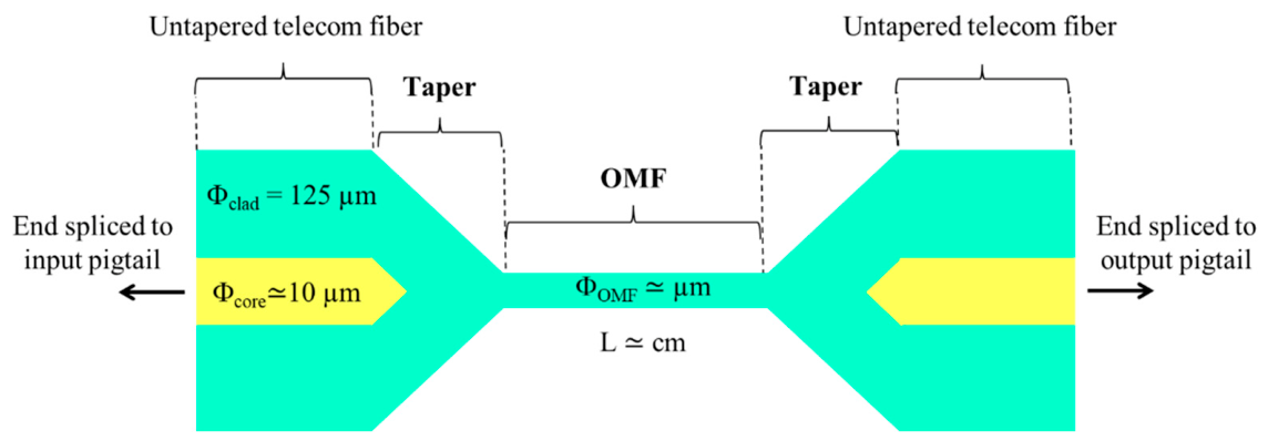
Figure 2.
Experimental setup. Top left image: view of the thermocouple and the OMF (red line) on the CMOS camera. Top right plot: output power versus position of the thermocouple on the device showing stability during the data acquisition.
Figure 2.
Experimental setup. Top left image: view of the thermocouple and the OMF (red line) on the CMOS camera. Top right plot: output power versus position of the thermocouple on the device showing stability during the data acquisition.
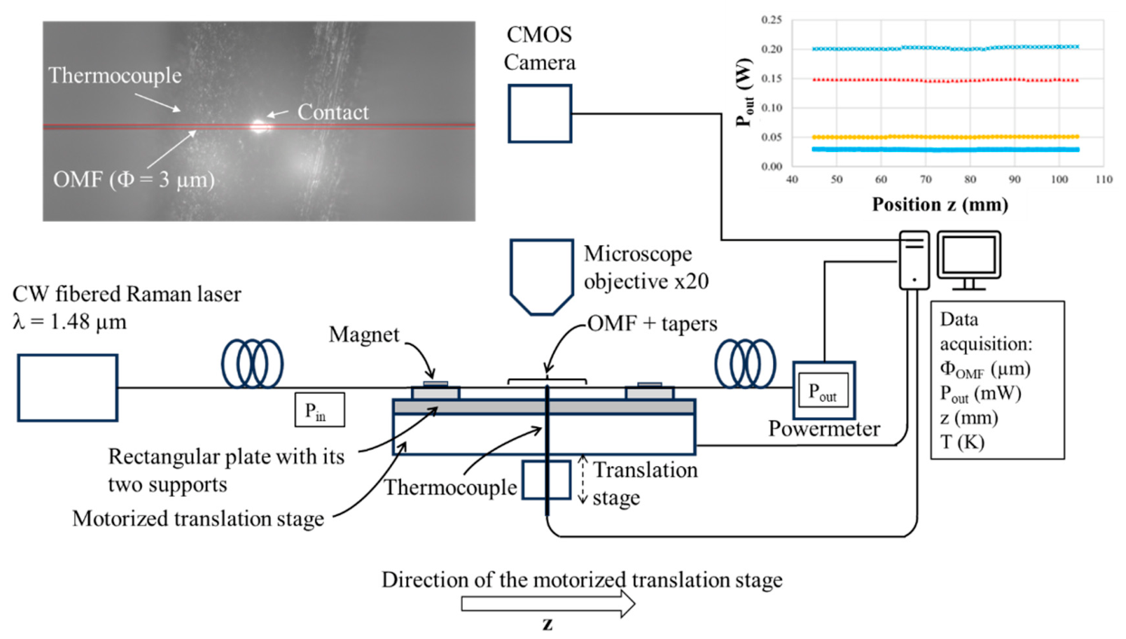
Figure 3.
Left axis: evolution of the temperature increase DT versus the position z along the device (blue stars). Right axis: radius of the device (right axis) versus the position z along the device (red dots). Numerical model plots are adjusted to experimental data (blue and red solid lines). The OMF has a diameter of 2.8 µm and a length of 10 mm. The length of a taper is 15 mm. The optical power coupled in the OMF part is 40 mW.
Figure 3.
Left axis: evolution of the temperature increase DT versus the position z along the device (blue stars). Right axis: radius of the device (right axis) versus the position z along the device (red dots). Numerical model plots are adjusted to experimental data (blue and red solid lines). The OMF has a diameter of 2.8 µm and a length of 10 mm. The length of a taper is 15 mm. The optical power coupled in the OMF part is 40 mW.
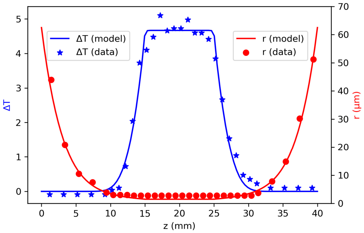
Figure 4.
Evolution of the temperature increase versus the coupled power in the OMF in mW for three different lengths and two different diameters (blue circles) and (green stars). The numerical model (solid lines) is adjusted to the experimental data and is represented with the values of and taken in the center of their respective uncertainty interval (a) ; (b) ; (c) .
Figure 4.
Evolution of the temperature increase versus the coupled power in the OMF in mW for three different lengths and two different diameters (blue circles) and (green stars). The numerical model (solid lines) is adjusted to the experimental data and is represented with the values of and taken in the center of their respective uncertainty interval (a) ; (b) ; (c) .
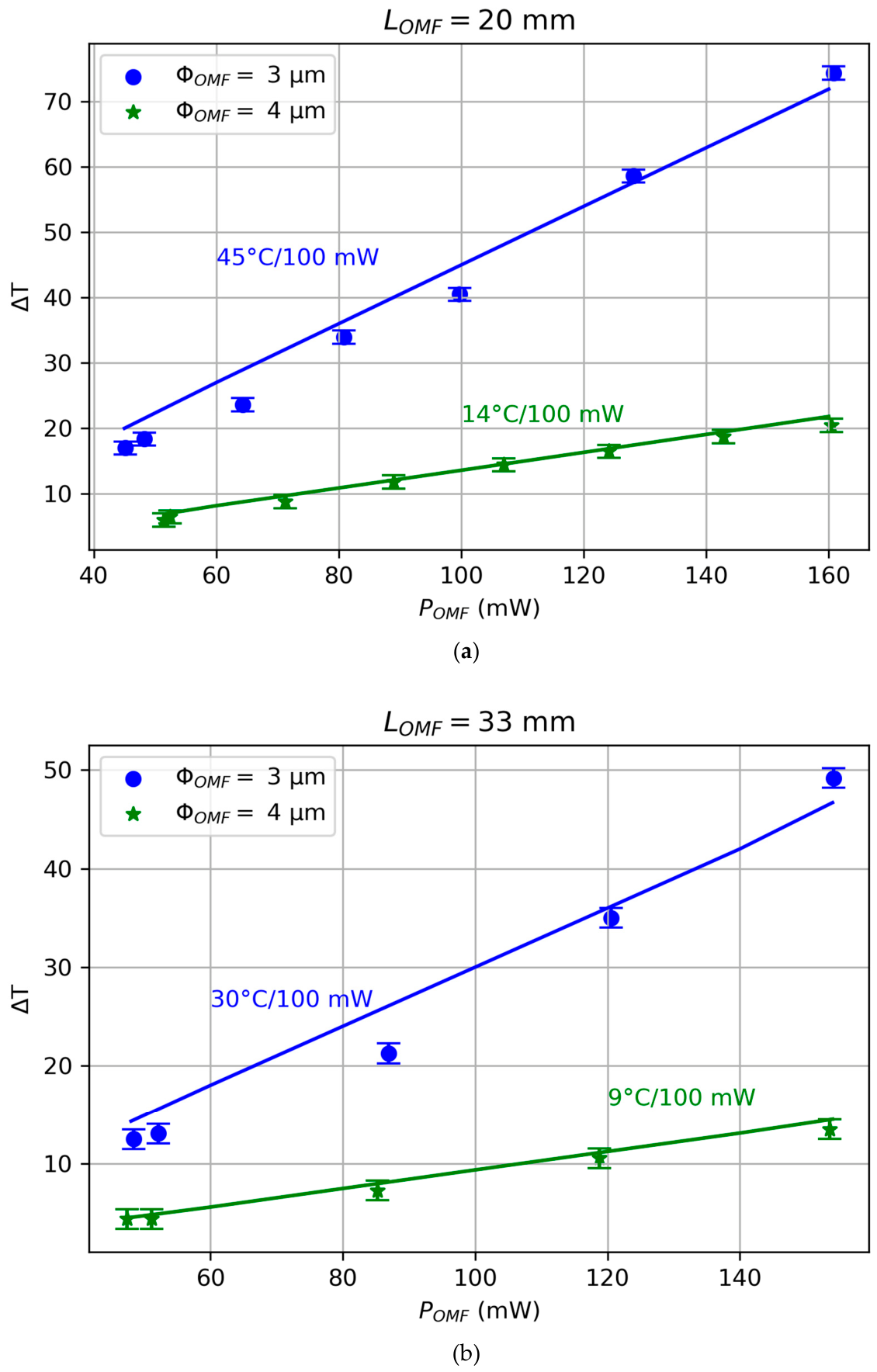
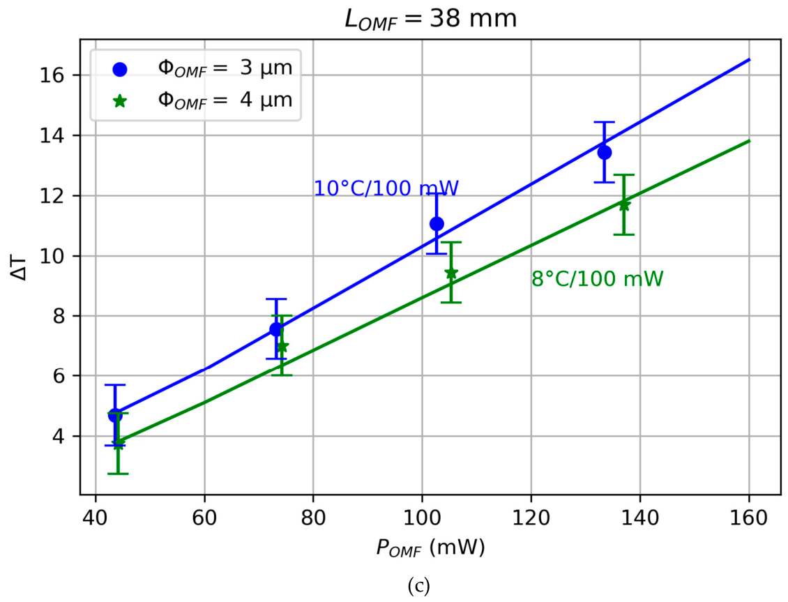

Table 1.
Summary of the values obtained for parameters and the rate of evolution for the different diameters and lengths tested.
Table 1.
Summary of the values obtained for parameters and the rate of evolution for the different diameters and lengths tested.
| 20 | 33 | 38 | 20 | 33 | 38 | |
| Rate | 45 °C/100 mW | 30 °C/100 mW | 10 °C/100 mW | 14 °C/100 mW | 9 °C/100 mW | 8 °C/100 mW |
Disclaimer/Publisher’s Note: The statements, opinions and data contained in all publications are solely those of the individual author(s) and contributor(s) and not of MDPI and/or the editor(s). MDPI and/or the editor(s) disclaim responsibility for any injury to people or property resulting from any ideas, methods, instructions or products referred to in the content. |
© 2026 by the authors. Licensee MDPI, Basel, Switzerland. This article is an open access article distributed under the terms and conditions of the Creative Commons Attribution (CC BY) license (http://creativecommons.org/licenses/by/4.0/).
Copyright: This open access article is published under a Creative Commons CC BY 4.0 license, which permit the free download, distribution, and reuse, provided that the author and preprint are cited in any reuse.


