
Submitted:
01 July 2026
Posted:
02 July 2026
You are already at the latest version
Abstract
Translating audit requirements into computable specifications for trusted digital infrastructure remains difficult. A major obstacle is the semantic disconnect between audit professionals and system architects during fintech system development. An additional challenge is embedding executable controls early with an appropriate degree of integration, rather than treating compliance mechanisms as an afterthought during later coding, integration and delivery across complex organizational and technical settings today. Drawing from process walkthroughs and software control mapping practices in internal auditing and systems examination, this study creates an audit evidence type and technical counterpart classification model, a mapping conversion matrix from audit assertions to system functions, and a verifiability-oriented control effectiveness verification algorithm. The methodology was illustrated through a practical digital asset management platform case. These results show that using the method in an architectural design phase creates a closed-loop constraint on controls, functions and evidence, decreasing interface changes, data fixups and test burdens arising when remedial actions are taken after development. It added a practical route to computer-engineering implementation for embedded compliance architecture and audit-ready system design within current software engineering practice.
Keywords:
computable audit requirements
; software architecture
; rule engine
; evidence lifecycle
; trusted digital infrastructure
1. Introduction
Critical infrastructure, digital asset platforms and cyber-physical business systems are increasingly required to provide continuous auditability, traceable evidence and embedded compliance controls during operation. Existing studies have established several important foundations. Henriques et al. focused on forensic acquisition, compliance auditing and event correlation in critical infrastructure protection, emphasizing evidence collection and security-oriented audit response[1]. Al-Zamil et al. discussed IoT-generated records as audit evidence and constructed a reasonable assurance framework, which strengthened the evidential value of machine-generated data in digital environments[2]. Seidenstein et al. examined disruptive technologies in audit and assurance, showing that automation, analytics and emerging digital tools are reshaping audit execution models[3]. Foehr et al. proposed a structured process-mining implementation framework for audit tasks, providing a procedural path for reconstructing business activities and identifying deviations[4]. Otoom further reviewed risk auditing for digital twins in cyber-physical systems, highlighting model-driven risk identification and continuous monitoring in complex infrastructures[5].
However, these studies mainly concentrate on evidence acquisition, audit automation, process reconstruction, risk monitoring or assurance technology adoption. Limited attention has been paid to how audit requirements can be translated into computable architectural elements during the system design phase. In particular, the mapping relationship among audit assertions, rule-engine logic, workflow state machines, access-control services and indexed evidence repositories remains insufficiently clarified. This gap makes audit controls easily become post-development patches rather than native constraints embedded in software architecture. To address this limitation, a rule-engine and evidence-indexing method is constructed to convert audit requirements into executable control rules, system functional modules and verifiable evidence objects. The method aims to support audit-ready architecture design, reduce later remediation costs, and improve the consistency among control execution, evidence generation and compliance verification.
2. Materials and Methods
2.1. Formal Modeling of Audit Requirements as Executable Control Rules
The transformation of audit requirements into system architecture in a formal computing pipeline rewrites textual control goals into executable constraints for workflow engines, access-control services and evidence repositories. Let the set of audit assertions be and the set of control rules be . Then, the mapping from assertions to rules is represented as , where denotes the th type of audit assertion, denotes the th control rule, and denotes the transformation function from audit semantics to rule logic.Furthermore, after deploying the rules to system functions, log links, and evidence objects, the verification objective function is defined as
where represents control coverage, represents evidence completeness, represents architectural modification cost, and , , and are weight coefficients.
2.2. Classification Model of Audit Evidence Types and Their Computational Counterparts
As shown in Figure 1, audit evidence can be classified into four categories: process, data, behavior, and trust, depending on the location and the level of validation [6]. Process evidence corresponds to workflow state transition records, with collected fields including process instance identifier , node number , and transition timestamp ; data evidence corresponds to version snapshots, field change sets, and data lineage chains; behavioral evidence corresponds to API call logs, authorization decision results, and exception trigger records; trust evidence corresponds to digital signatures, hash digests, and trusted timestamps [7]. The classification mapping function is defined as
where is the th audit evidence object, is the type of the evidence’s technical counterpart, is the storage structure, and is the verification method. During implementation, evidence is first written to the process repository, log repository, version repository, and summary index repository based on event source tags, then cross-repository binding is performed using the association key , where is generated by concatenating the business object identifier, operator identifier, and a millisecond-level time window [8].Both SHA-256 digests and Ed25519 signatures are used for high risk nodes; for cross-service call chains, the TraceID combination is used to create a searchable, classified evidence graph.
2.3. Conversion Matrix from Audit Assertions to System Functional Modules
First, the assertions of integrity, authorization, traceability, and non-repudiation are encoded into an assertion vector . Then, a mapping matrix is generated based on the process node risk weights and functional priorities . The calculation formula is
where represents the mapping strength from the th category of audit assertions to the th system function, represents the assertion constraint value, represents the node risk weight, and represents the function implementation priority. When , the corresponding control is written into a rule engine and distributed at the same time to a workflow state machine, an Access Control Service, an Audit Log Service, and a Proof Index Service [9]. The specific conversion matrix is shown in Table 1.
2.4. Trusted Software Architecture Driven by Control Mapping
The system adopts three software layers: "Business Orchestration Layer — Control Execution Layer — Evidence Foundation Layer." The Business Orchestration Layer is in charge of the process instance scheduling, state transformation verification, and exception branch containment; the Control Execution Layer handles rule matching, role-based access control, interface authentication, and signed calls; and the Evidence Foundation Layer handles log aggregation, release snapshot, summary indexing, and audit.During deployment, control items are first registered as policy units according to the transformation matrix, with rule priority , trigger threshold , and TTL configured. Process events are delivered through a unified event bus. Dual-channel writing is enabled at key transaction nodes: the business database stores main data, and the evidence database simultaneously writes TraceID, operator ID, timestamp, and hash value under state-machine constraints. Fine-grained interface tokens and millisecond time windows ensure that control execution, evidence generation, and query chains remain computationally consistent. Each transaction is therefore replayable, verifiable and retrievable through the query service.
2.5. Control Point Extraction and Rule Orchestration Based on Event Replay
During the process simulation stage, as illustrated in Figure 2,event-log replay is performed on the business flow. For registration, approval, modification, transfer, and archiving, six fields are parsed: process instance identifier, node number, operator role, resource object identifier, timestamp, and return status. A rule-based path scan is then executed over critical nodes, unauthorized access paths, and evidence gaps to locate high-risk control points. For cross-service links, TraceIDmerging is applied, and the high frequency nodes are set with a sliding time window Δt = 500 ms to identify paths involving bypassed approvals, duplicate submissions, and abnormal rollbacks [10].
Once control points are determined, audit assertions are decomposed into condition items, action items, and evidence items, and orchestrated into executable rule chains. The rule engine is loaded based on priority , trigger threshold , role conflict set , and timeout parameter TTL=900 s. The workflow state machine checks the completeness of the previous node, the access control service handles the minimum privilege determination, and the logging service generates a structured audit record.Double-rule binding is enabled for high risk nodes, with the primary control rule governing the service status transition, and the secondary control rule checks the consistency of signatures, timestamps, and evidence indices.
2.6. Evidence Lifecycle Management and Indexed Storage Mechanism
The evidence life cycle, as illustrated in Figure 3, consists of five phases: generation, binding, storing, retrieving, and archiving. During generation, the workflow engine, interface gateway, and logging proxy serialize event evidence synchronously; during binding, the business object identifier , process instance identifier , operator identifier , trace identifier (TraceID), and millisecond-level timestamp are written into a unified metadata header;The storage phase employs a "business repository + evidence repository + summary index repository" layered write strategy. High-risk evidence is protected by SHA-256 hashes, Ed25519 signatures, immutable object locking, and a 30-day hot/cold binding threshold. Each object retains searchable version and event links for audits.
The evidence quality score is defined as
where is the evidence quality score, is the integrity metric, is the temporal consistency metric, is the associative integrity metric, is the verifiability metric, and through are weighting coefficients. In the retrieval phase, a combination of object keys, event keys, and time windows is used, and the archiving phase performs version freezing and validation recalculations based on retention levels.
2.7. Control Effectiveness Verification Protocol for Release Testing
Control effectiveness verification is implemented as a three-layer software test protocol of "structure verification — behavior replay — evidence review." The Structure Verification Stage examines the deployment of Control Points at Destination, Interface Entry Point, and State Transition Boundary, and verifies Policy Identifiers, Version Numbers, Priorities, and Time-To- Live (TTL) values ; the behavioral replay phase injects into the workflow engine four kinds of test events — normal, unauthorized, rollback, and timeout, recording access control results, status machine return codes, and audit log sequences; in the evidence validation stage, the consistency ofTraceID, signature values, timestamps, digest values, and index keys are validated. Control validity is defined as
where is the control validity score, is the protocol test pass rate, is the evidence completeness rate, and is the weighting coefficient. A control item is included in the release list only when and the evidence for the exception path is closed.
3. Results and Discussion
3.1. Business Process Modeling and Audit Scenario Construction
The Digital Asset Management Platform is based on six major processes: asset registration, ownership verification, approval process, status change, authority handover, and filing/freezing. At the business level, the asset objectidentifier asset_id is used as the main key, linking the application form, the approval form, the operation log, and the evidence index; at the process level, the finite state machine controls the transition from "Draft — Pending Review — Approved — Effective — Frozen — Archived," which prohibits cross-level jumps; the audit layer configures scenarios around authenticity, integrity, authorization, and non-repudiation. The registration phase focuses on verifying the consistency of source document hashes, the role of the data entry user, and timestamps;The approval phase monitors dual-review, role mutual exclusion sets , and timeout thresholds TTL=900 s; the status change phase binds version numbers , change difference sets, and TraceIDs; the authorization handover phase verifies that the old authorization is revoked, the new authorization is activated, and the approval record is closed. The system uniformly outputs a structured event stream, which provides input for later architecture mapping and proof validation.
3.2. Implementation of Audit-to-Architecture Mapping Services
As illustrated in Figure 4, audit requirements are decomposed into machine-readable fields, including assertion type, target object, trigger condition, constraint action, and evidence requirement, and are then mapped to control units such as access control, state-machine verification, log tracing, signature verification, and index archiving. The platform implements these units through authentication, authorization, version control, logging, and evidence-indexing services. Finally, business records, evidence records, and summary indexes are generated simultaneously along the write path, with SHA-256 and Ed25519 dual verification enabled for high-risk nodes. This produces a deployable path rather than a manual audit checklist.
3.3. Comparative Analysis of System Performance and Remediation Costs
Two implementation scenarios were configured to evaluate the computing effect of the method: Scenario A adds audit controls after development is complete, whereas Scenario B embeds the control map during architectural design. The validation scope covers five core processes: asset registration, status change, approval workflow, authorization handover, and filing/freezing. The tracked metrics include control coverage, evidence completeness, interface modification count, data-structure patch count, regression-test cases, remediation man-hours, average query response time, and anomaly-path closure rate. In the pre-embedded method, assertion decomposition and module mapping were completed during requirement review, so access control, state-machine constraints, log fields, summary indexes, and signature interfaces were integrated into the original architecture. In contrast, post-embedding requires interface validation, field extension, traceability identifiers, and evidence indexes after deployment. Table 2 reports the comparison, and Figure 5 visualizes the performance and cost differences for engineering discussion analysis.
As shown in Table 2, the main cost of post-implementation remediation concentrates on cross-module rework, database patching, and regression testing. Interface modifications decrease from 24 to 7, data-structure patches from 16 to 3, regression cases from 143 to 58, and remediation hours from 247 to 86 after upfront embedding. These differences indicate that computer-level control mapping constrains changes to policy settings and index configuration without rewriting core transaction paths. It also improves query response time and anomaly path closure metrics jointly.
As illustrated in Figure 5, the clustered bar chart compares control coverage, evidence completeness, verification pass rate, and exception-path closure rate, while the waterfall chart decomposes remediation effort into five stages: requirements analysis, interface modification, data patching, regression testing, and release validation. The improvement in control coverage is mainly produced by dual-rule binding at high-risk nodes and pre-validation within the state machine. The increase in evidence completeness is attributed to standardized metadata headers, consolidated cross-service TraceIDs, and synchronous writing to the evidence repository. Front-end changes are limited to rule configuration, evidence indexing, and audit-query interfaces, whereas back-end changes involve validation workflows, main tables, the message bus, and archiving services. This discussion links each data pattern to a specific computing mechanism rather than only describing audit performance, thereby meeting the results-discussion requirement.
4. Conclusions
By introducing audit requirements into system architecture, the article forms a computer-engineering methodology chain covering assertion parsing, rule mapping, evidence-lifecycle management, and control-validity verification, and implements it in phases within the Digital Asset Management Platform. The contribution lies in converting compliance semantics into deployable rule engines, state-machine constraints, indexed evidence objects, and verifiable service interfaces. Remaining limitations include scenario coverage and adaptability to cross-platform heterogeneous systems. Future work may extend toward multi-cloud architectures, on-chain and off-chain collaborative evidence preservation, and auditable intelligent agents.
References
- Henriques J, Caldeira F, Cruz T, et al. A survey on forensics and compliance auditing for critical infrastructure protection[J]. IEEE Access, 2024, 12: 2409-2444. [CrossRef]
- Al-Zamil Z S, Appelbaum D A, Nehmer R A. IoT as audit evidence: A reasonable assurance framework[J]. Journal of Emerging Technologies in Accounting, 2024, 21(2): 35-51. [CrossRef]
- Seidenstein T, Marten K U, Donaldson G, et al. Innovation in audit and assurance: A global study of disruptive technologies[J]. Journal of Emerging Technologies in Accounting, 2024, 21(1): 129-146. [CrossRef]
- Foehr T L, Reichelt V, Marten K U, et al. A framework for the structured implementation of process mining for audit tasks[J]. International Journal of Accounting Information Systems, 2025, 56: 100727. [CrossRef]
- Otoom S. Risk auditing for Digital Twins in cyber-physical systems: A systematic review[J]. Journal of Cyber Security and Risk Auditing, 2025, 2025(1): 22-35.
- Biškupić I O, Balković M, Bencarić I. An Evidence-Based Architecture for Trustworthy Asset Discovery in Cybersecurity-Critical IT Environments[J]. Journal of Cybersecurity and Privacy, 2026, 6(2): 67. [CrossRef]
- Al-Zamil Z S, Appelbaum D A, Nehmer R A. IoT as audit evidence: A reasonable assurance framework[J]. Journal of Emerging Technologies in Accounting, 2024, 21(2): 35-51. [CrossRef]
- Kacianka S, Pretschner A. Designing accountable systems[C]//Proceedings of the 2021 ACM conference on fairness, accountability, and transparency. 2021: 424-437.
- Brelih A, Klinc R. Building digital trust in CDE-based BIM workflows: Key strategies[J]. Journal of Information Technology in Construction, 2025, 30. [CrossRef]
- Foehr T L, Reichelt V, Marten K U, et al. A framework for the structured implementation of process mining for audit tasks[J]. International Journal of Accounting Information Systems, 2025, 56: 100727. [CrossRef]
Figure 1.
Association and Classification Diagram of Audit Evidence Types and Computational Counterparts.
Figure 1.
Association and Classification Diagram of Audit Evidence Types and Computational Counterparts.
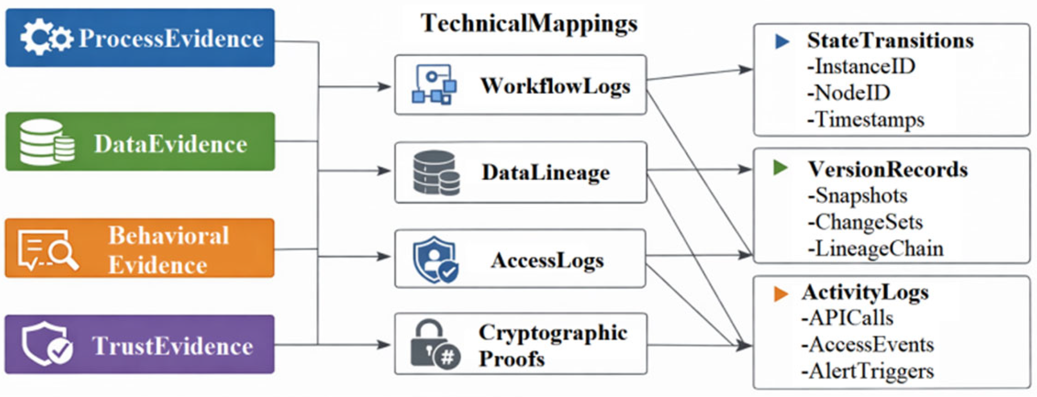
Figure 2.
Flowchart of Control Point Extraction and Rule Orchestration Driven by Event-Log Replay.
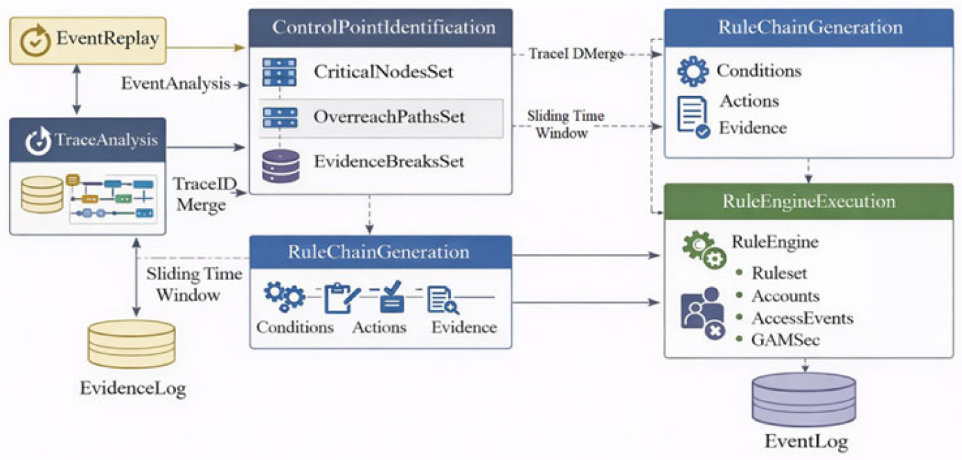
Figure 3.
Audit Evidence Lifecycle and Indexed Storage Mechanism Diagram.
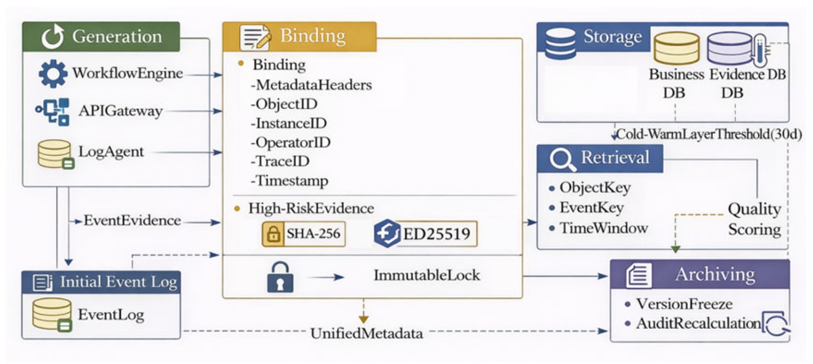
Figure 4.
Step-by-Step Mapping from Audit Requirements to Platform Architecture Implementation.
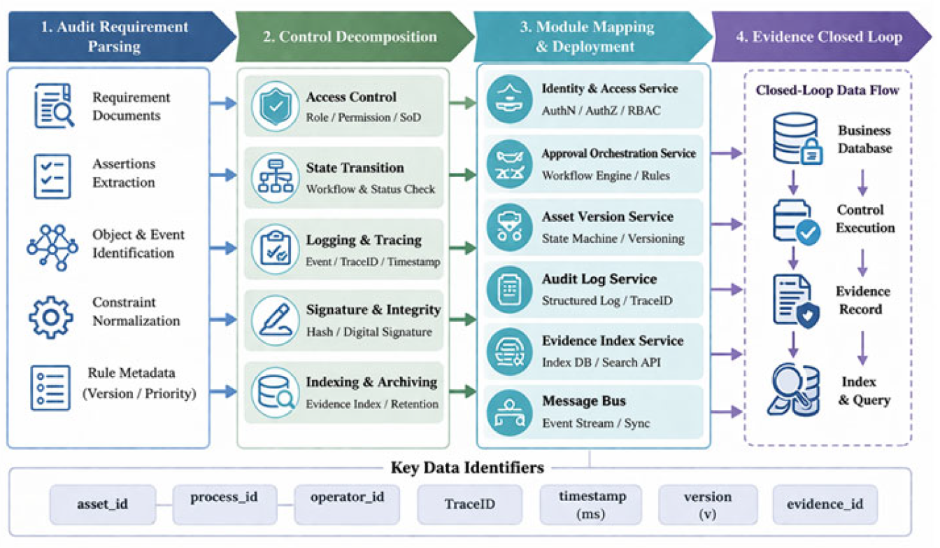
Figure 5.
Combined Comparison of System Performance and Remediation Cost Before and After Control Embedding.
Figure 5.
Combined Comparison of System Performance and Remediation Cost Before and After Control Embedding.
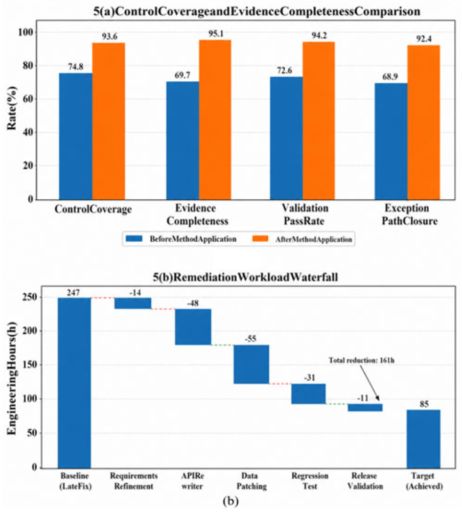

Table 1.
Conversion Matrix from Audit Assertions to System Functions.
| Audit Assertion | Control Decomposition Items | System Functional Module | Key Parameter Configuration | Output Evidence Object |
| Integrity | Version Locking, Change Validation, Digest Comparison | Version Management Service, Data Validation Service | Version number v, digest algorithm SHA-256S, change window Δt=1 s | Version Snapshot, Difference Record, Digest Value |
| Authorization | Identity Authentication, Role Exclusion, Least Privilege Determination | Identity Authentication Service, Role-Based Access Control Service | Token Time-to-Live (TTL) = 900 s, Role Conflict Set (Rc), Permission Granularity g = API Level | Login records, authorization decision logs |
| Traceability | Global identifier generation, call chain merging, node tracing | Workflow Engine, Trace Service, Log Service | Trace ID, node ID (nid), time precision (milliseconds) | State transition records, call chain records |
| Non-repudiation | Digital signatures, trusted timestamps, dual-person confirmation | Signature service, timestamp service, approval service | Signature algorithm: Ed25519; timestamp deviation ≤ 10 ms; number of verifiers: k=2 | Signature credentials, time proofs, approval records |
Table 2.
Comparison of Engineering Costs Between Upfront Embedding and Post-Deployment Rectification.
Table 2.
Comparison of Engineering Costs Between Upfront Embedding and Post-Deployment Rectification.
| Metrics | Pre-embedded | Post-fix corrections |
| Control Coverage /% | 93.6 | 74.8 |
| Evidence Completeness Rate/% | 95.1 | 69.7 |
| Number of interface modifications | 7 | 24 |
| Number of data structure patches | 3 | 16 |
| Number of modules requiring rework | 4 | 11 |
| Number of regression test cases | 58 | 143 |
| Batches of historical data backfill | 0 | 9 |
| Remediation Hours/h | 86 | 247 |
| Average audit query response time (ms) | 182 | 436 |
| Anomaly path closure rate /% | 92.4 | 68.9 |
Disclaimer/Publisher’s Note: The statements, opinions and data contained in all publications are solely those of the individual author(s) and contributor(s) and not of MDPI and/or the editor(s). MDPI and/or the editor(s) disclaim responsibility for any injury to people or property resulting from any ideas, methods, instructions or products referred to in the content. |
© 2026 by the authors. Licensee MDPI, Basel, Switzerland. This article is an open access article distributed under the terms and conditions of the Creative Commons Attribution (CC BY) license (http://creativecommons.org/licenses/by/4.0/).
Copyright: This open access article is published under a Creative Commons CC BY 4.0 license, which permit the free download, distribution, and reuse, provided that the author and preprint are cited in any reuse.


