

Submitted:
27 June 2026
Posted:
01 July 2026
You are already at the latest version
Abstract
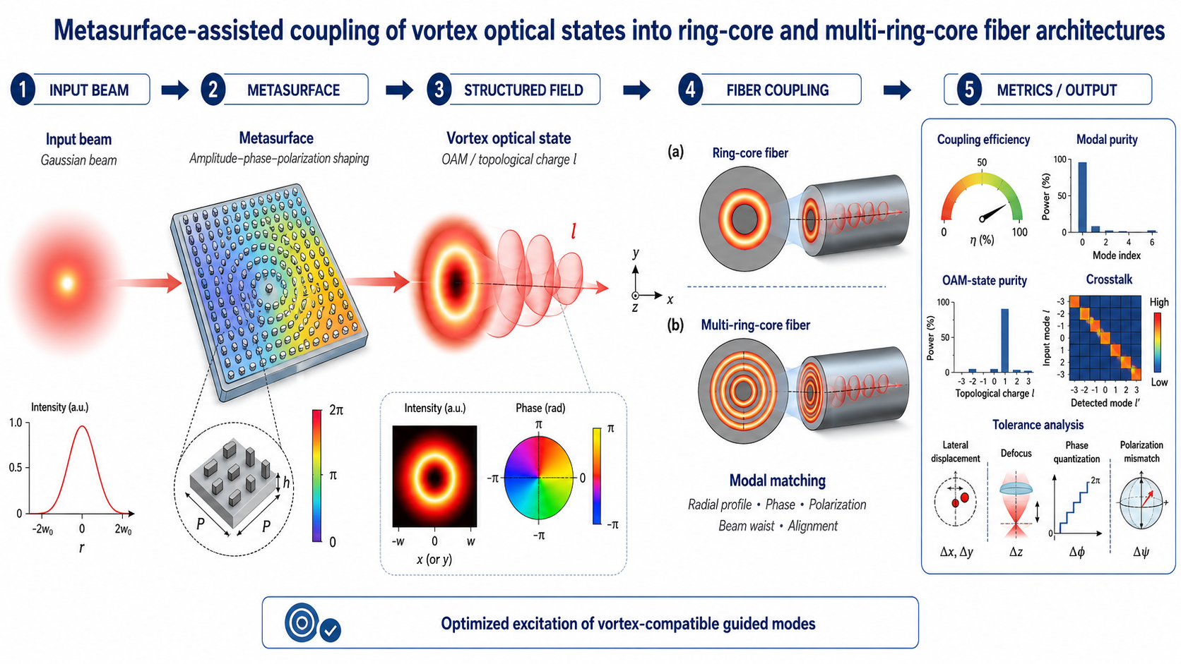
Vortex optical states carrying orbital angular momentum provide an additional degree of freedom for fiber photonic systems [1-3], but their practical use requires efficient and reproducible excitation of guided modes with compatible transverse field structures. Ring-core and multi-ring-core fibers are natural platforms for such states because their annular guiding geometry can support modes with azimuthal phase variation [4-13]. However, a freely generated vortex beam does not automatically provide selective excitation of a prescribed guided mode. In this work, we develop a metasurface-assisted modal-matching framework for coupling vortex optical states into ring-core and multi-ring-core fiber architectures. The metasurface is treated not only as a vortex generator, but as a compact input interface that forms an amplitude–phase–polarization field profile optimized for a target vortex-compatible guided mode. A scalar modal-overlap model is used to evaluate target-mode coupling efficiency, modal purity, OAM-state purity, crosstalk, insertion loss, and tolerance sensitivity. The simulations show that a simple vortex field with the correct azimuthal order provides perfect OAM-state purity in the scalar basis, but only 0.616 target-mode coupling efficiency and 2.10 dB insertion loss. After radial modal matching, the coupling efficiency increases to 0.975 and the insertion loss decreases to 0.11 dB, while other-ring leakage is strongly suppressed. Practical non-idealities are also quantified: eight-level phase quantization still gives 0.950 coupling efficiency, whereas random phase errors with standard deviation reduce it to 0.856. The tolerance analysis identifies lateral displacement, beam-waist mismatch, ring-radius mismatch, phase noise, and polarization mismatch as the dominant limitations. The proposed framework provides a quantitative basis for designing structured-light input interfaces for selective excitation of vortex-compatible modes in annular fiber architectures.
Keywords:
structured light
; vortex optical states
; orbital angular momentum
; ring-core fiber
; metasurface coupling
; modal matching
; crosstalk
; tolerance analysis
1. Introduction
1.1. Structured Light and Vortex Optical States
Structured light refers to optical fields whose spatial distribution, phase, polarization, or angular momentum is deliberately engineered rather than treated as a simple Gaussian beam. Among such fields, vortex optical states are of particular interest because they contain a phase singularity and an azimuthally varying phase profile. In an ideal scalar representation, this phase dependence can be described by a helical phase factor, where the integer topological charge determines the number of phase rotations around the beam axis. As a result, the optical field carries orbital angular momentum and exhibits a characteristic annular intensity distribution with a low-intensity region near the phase singularity [1,2].
The presence of orbital angular momentum provides an additional degree of freedom for photonic systems. In contrast to conventional encoding based only on intensity, wavelength, time slot, or polarization, vortex states can in principle be distinguished by their topological charge, radial structure, and polarization–spatial composition. This makes them attractive for mode-division multiplexing, high-dimensional optical communication, mode-selective routing, optical manipulation, and advanced photonic information processing [2,3]. In fiber-based systems, vortex-compatible modes may also serve as separate spatial channels, provided that they can be selectively excited, transmitted, and detected with sufficiently low crosstalk [3,4,5].
However, practical use of vortex optical states in guided photonic architectures is not determined by vortex generation alone. A free-space vortex beam produced by a phase plate, spatial light modulator, holographic element, or metasurface does not automatically excite the desired guided mode of a fiber. Efficient coupling requires simultaneous matching of several field properties at the fiber input plane: the radial intensity profile, azimuthal phase distribution, polarization state, beam waist, numerical aperture, and alignment with the guiding region. If these conditions are not satisfied, a significant part of the input power may be coupled into unwanted radial, azimuthal, or polarization modes, or may remain unguided.
This issue is especially important for ring-core and multi-ring-core fiber architectures. Their annular guiding geometry is naturally compatible with vortex-like transverse fields, but the coupling efficiency depends strongly on how well the incident structured beam matches the target guided mode. Therefore, the problem should be formulated not only as the generation of an optical vortex, but as the controlled formation of a mode-matched input field. In this work, this role is assigned to a metasurface, which is considered as a compact optical interface for preparing an amplitude–phase–polarization distribution optimized for coupling into selected vortex-compatible guided modes.
1.2. Ring-Core and Multi-Ring-Core Fibers as Natural Platforms for Vortex Modes
Ring-core fibers represent a particularly suitable class of guided photonic structures for vortex optical states. Unlike conventional single-mode fibers, where the guided field is concentrated near the fiber axis and is usually well approximated by a fundamental Gaussian-like mode, a ring-core fiber contains an annular guiding region. This geometry is naturally compatible with optical fields whose intensity is distributed around the axis and whose phase varies azimuthally. As a result, the transverse structure of a vortex beam can be better matched to the guided modes of a ring-core fiber than to the fundamental mode of a standard single-core fiber [6,7,8,11].
It is important to clarify the terminology. In this work, a ring-core fiber does not mean a conventional optical fiber bent into a circular loop. Rather, it refers to a structured fiber in which the light-guiding region has an annular cross-section. In such a fiber, the refractive-index profile is designed so that the optical field is guided mainly within a ring-shaped region around the central axis. A multi-ring-core fiber extends this concept by introducing several concentric annular guiding regions within a single structured fiber. These rings may serve as distinct radial channels or as coupled guiding regions depending on the index profile, ring separation, and modal overlap.
The circular symmetry of ring-core fibers is essential for supporting vortex-compatible guided modes. A vortex optical state is characterized by an azimuthal phase dependence, and such a phase structure is naturally associated with cylindrical coordinates. Therefore, a waveguide with annular symmetry can provide a more appropriate modal basis for OAM-like states than a waveguide with a strongly localized central core. In an idealized structure, different azimuthal orders may be associated with different vortex-like modal states, while the radial structure is determined by the geometry and refractive-index contrast of the guiding ring.
Multi-ring-core geometries provide additional design flexibility. By introducing several concentric annular guiding regions, it becomes possible to control not only the azimuthal structure of the field but also its radial distribution. In principle, different rings may support different radial mode families, provide additional spatial degrees of freedom, or enable selective coupling between neighboring annular regions. This makes multi-ring-core fibers attractive for structured-light transmission, mode-division multiplexing, and more advanced fiber photonic architectures in which information may be encoded not only in wavelength, time, or polarization, but also in spatial and topological features of the optical field [8,9,10,11,12].
However, the presence of an annular guiding region alone is not sufficient to guarantee efficient excitation of a desired vortex-compatible mode. The incident field must be matched to the target mode in both radial and azimuthal structure. If a free-space vortex beam has an inappropriate ring radius, beam waist, polarization state, or numerical aperture, it may excite a mixture of guided modes rather than a single target state. In multi-ring-core fibers, this problem becomes even more important because the input field may unintentionally couple to neighboring radial channels or to modes with similar azimuthal structure [9,10,11,12,13].
For this reason, ring-core and multi-ring-core fibers should be considered not only as passive carriers of vortex states, but as modal platforms that require carefully designed input coupling. The coupling interface must prepare a field whose amplitude, phase, and polarization are compatible with the selected guided mode. This requirement motivates the use of a metasurface as a compact mode-matching element capable of tailoring the input field before it enters the fiber.
1.3. Coupling Problem
The generation of a vortex beam in free space does not by itself ensure efficient excitation of a selected guided mode in a ring-core fiber. A vortex beam is usually characterized by its topological charge and annular intensity distribution, but these parameters describe only part of the field structure required for coupling. In a guided system, the input field must be projected onto the eigenmodes supported by the fiber. Therefore, the coupling efficiency is determined by the full complex-field overlap between the incident optical field and the target guided mode [11].
For a ring-core fiber, the topological charge of the input beam is a necessary but not sufficient condition for selective mode excitation. Two beams with the same azimuthal phase order may have very different radial intensity profiles, beam waists, divergence angles, polarization states, and phase curvatures. If these parameters are not matched to the target mode, the incident field may excite several guided modes simultaneously or may couple only weakly into the fiber [11]. In this case, the output field may still visually resemble an annular beam, but its modal purity and orbital-angular-momentum-state purity can be low.
The radial structure is particularly important. A ring-core guided mode is confined mainly within an annular region whose radius and width are defined by the refractive-index profile of the fiber. If the input vortex beam has a ring radius that is smaller or larger than the guiding region, a substantial fraction of the optical power will not overlap with the desired mode. Similarly, an inappropriate beam waist or numerical aperture can lead to coupling into higher-order radial modes or to radiation loss.
The phase distribution must also be matched beyond the simple presence of an azimuthal phase term. The incident field may include wavefront curvature, phase errors, finite-aperture effects, or phase quantization introduced by the beam-forming element. These factors can reduce the overlap with the target mode and increase crosstalk to neighboring azimuthal or radial modes. In multi-ring-core fibers, phase and radial mismatch may additionally cause undesired excitation of modes associated with adjacent annular guiding regions.
Polarization provides another important degree of freedom. In ideal scalar treatments, vortex beams are often described only by their spatial phase. However, realistic fiber modes may have hybrid vector structure, polarization degeneracy, or coupling between spin and orbital contributions. As a result, a field with the correct topological charge but an unmatched polarization state may still fail to excite the desired guided mode efficiently. Therefore, polarization matching should be considered together with amplitude and phase matching.
Alignment is equally critical. Lateral displacement, angular tilt, and defocusing at the fiber input plane break the cylindrical symmetry of the coupling process and may strongly degrade selective excitation of vortex-compatible modes. This is especially relevant for practical systems, where the metasurface, focusing optics, and fiber facet must be aligned with finite mechanical tolerance. A realistic coupling model should therefore evaluate not only the ideal overlap, but also the sensitivity of coupling efficiency and modal purity to alignment errors.
Thus, the coupling problem should be formulated as a complete modal-matching problem. The goal is not simply to generate a vortex beam with a specified topological charge, but to prepare an input field whose amplitude, phase, polarization, spatial scale, and propagation geometry are optimized for a selected guided mode of a ring-core or multi-ring-core fiber. This formulation motivates the use of a metasurface as a compact field-engineering interface capable of tailoring the incident beam for efficient and reproducible excitation of vortex-compatible fiber modes.
1.4. Role of Metasurfaces
Metasurfaces provide a compact and highly flexible platform for engineering optical fields at the subwavelength or wavelength scale. By tailoring the geometry, orientation, and arrangement of their constituent elements, metasurfaces can impose a prescribed spatial response on an incident optical beam. Depending on the design, this response may include phase modulation, amplitude shaping, polarization conversion, wavefront focusing, beam deflection, or the generation of structured optical fields [14,15,16,17]. This makes metasurfaces attractive as planar optical elements for replacing or complementing conventional bulk components such as lenses, phase plates, holograms, and polarization optics.
In the context of vortex optical states, metasurfaces are often used to generate beams with an azimuthally varying phase profile and a specified topological charge. A conventional implementation may focus mainly on producing the helical phase structure required for orbital angular momentum. However, for coupling into a guided fiber mode, this is not sufficient. The field at the fiber input facet must match the target mode not only in its topological charge, but also in its radial intensity distribution, phase curvature, polarization state, numerical aperture, and spatial alignment. Therefore, in the present work, the metasurface is considered not merely as a vortex-beam generator, but as a mode-matching interface.
This distinction is central to the proposed approach. A metasurface designed only to generate a free-space vortex beam may produce a visually correct annular intensity pattern and phase singularity, while still providing poor overlap with a selected ring-core fiber mode. In contrast, a metasurface designed for modal matching should synthesize the complex optical field required at the fiber input plane. Such a field should reproduce, as closely as possible, the amplitude, phase, and polarization structure of the target vortex-compatible guided mode. In this sense, the metasurface acts as a compact coupling element between a conventional incident beam and a structured fiber mode.
For ring-core and multi-ring-core fiber architectures, this functionality is particularly important. The annular geometry of the guiding region requires radial control of the input intensity profile, while the vortex nature of the desired state requires azimuthal phase control. If vector modes or polarization-sensitive coupling are considered, the metasurface may also need to shape the local polarization distribution. Thus, a properly designed metasurface can simultaneously provide radial mode matching, azimuthal phase matching, focusing, and polarization preparation [15,17,19].
The use of metasurfaces also enables a systematic tolerance-oriented design. Since the metasurface defines the input field in a compact planar form, its design parameters can be directly related to coupling efficiency, modal purity, and crosstalk. Phase quantization, finite aperture, fabrication-induced phase errors, polarization conversion efficiency, and alignment sensitivity can all be included in the coupling model. This allows the metasurface to be evaluated not only as an ideal field generator, but also as a practical optical interface with measurable performance limits [15,17,19,20].
Therefore, the role of the metasurface in this work is twofold. First, it prepares a vortex optical state with the required spatial and polarization structure. Second, it performs modal matching between the incident beam and a selected guided mode of a ring-core or multi-ring-core fiber. This approach shifts the design objective from simple vortex generation to efficient and reproducible excitation of a prescribed guided mode.
1.5. Aim and Contribution of This Work
The aim of this work is to develop a theoretical and numerical framework for metasurface-assisted coupling of vortex optical states into ring-core and multi-ring-core fiber architectures. The central problem addressed here is not the generation of a vortex beam as a free-space optical field, but the controlled excitation of a selected vortex-compatible guided mode in a structured fiber. This requires modal matching between the field formed by the metasurface and the eigenmode supported by the fiber.
The proposed approach treats the metasurface as a compact input interface that transforms an incident beam into a field with a prescribed amplitude, phase, and polarization distribution at the fiber input plane. In this formulation, the metasurface is designed to maximize the overlap with a target guided mode rather than only to impose a helical phase profile. This distinction is important because a visually well-formed vortex beam may still exhibit poor coupling efficiency or low modal purity if its radial profile, wavefront curvature, polarization state, or spatial scale does not match the fiber mode.
The first contribution of this work is the formulation of a modal model for vortex-compatible states in ring-core and multi-ring-core fiber geometries. The model identifies the relevant field parameters that determine coupling into annular guided modes, including the radial intensity profile, azimuthal phase order, polarization structure, and spatial localization within one or several ring-shaped guiding regions.
The second contribution is the development of a metasurface-assisted field-formation concept for coupling into selected guided modes. The metasurface is considered as a mode-matching element capable of combining vortex phase generation with radial field shaping, focusing, and, when required, polarization preparation. This provides a more targeted coupling strategy than using a conventional vortex generator followed by standard focusing optics.
The third contribution is the introduction of an overlap-based quantitative framework for evaluating coupling performance. The main metrics include coupling efficiency into the target mode, modal purity, orbital-angular-momentum-state purity, and crosstalk to neighboring radial, azimuthal, and polarization modes. These metrics allow the coupling process to be described not only qualitatively, but also in terms of measurable and comparable performance parameters.
The fourth contribution is a metrological tolerance analysis of the coupling interface. The influence of realistic imperfections, such as lateral displacement, angular tilt, defocusing, beam-waist mismatch, radial-profile mismatch, phase quantization, phase errors, and polarization mismatch, is evaluated in terms of degradation of coupling efficiency and modal purity. This analysis is intended to define practical design and alignment requirements for metasurface-assisted excitation of vortex-compatible fiber modes.
The scope of this work is deliberately limited to the input-coupling and modal-matching problem. Long-distance propagation stability, mode coupling under fiber bending, active switching, mode-selective routing, and experimental interferometric verification are not treated as primary objectives here and are left for subsequent studies. This restriction allows the present work to focus on the fundamental and metrological conditions required for reproducible excitation of vortex optical states in ring-core and multi-ring-core fiber photonic architectures.
2. Physical Model of Ring-Core and Multi-Ring-Core Fiber Modes
2.1. Geometry of the Fiber Architecture
The fiber architectures considered in this work are based on annular guiding regions embedded in a lower-index cladding. They should not be confused with a conventional optical fiber bent into a circular loop. A ring-core fiber is a structured optical fiber whose light-guiding region has an annular cross-section. A multi-ring-core fiber extends this concept by introducing several concentric annular guiding regions within the same fiber cross-section. The optical axis of the fiber is taken along the propagation direction z, while the transverse field structure is described in cylindrical coordinates.
The simplest geometry is a single ring-core fiber, illustrated in Figure 1a. The guiding region is defined by an inner radius and an outer radius . The ring width is therefore . The refractive index of the annular core is denoted as , while the surrounding cladding has refractive index . In the idealized step-index model, the guiding region is described by a positive refractive-index contrast . This model captures the essential feature required for vortex-compatible guidance: the optical field is confined mainly in an annular region rather than near the fiber axis [6,7,8,11,12].
The annular geometry is naturally compatible with transverse fields that have a ring-like intensity distribution and an azimuthal phase dependence. In such a structure, the radial position of the guiding region can be adjusted to match the radial maximum of an incident vortex beam, while the circular symmetry provides a convenient modal basis for fields with angular phase variation. In practice, the exact supported modes depend on the ring radius, ring width, refractive-index contrast, wavelength, and polarization structure.
A multi-ring-core fiber is shown schematically in Figure 1b. In this case, several annular guiding regions are introduced at different radial positions. The j-th ring can be described by its inner radius , outer radius , width , and refractive-index contrast relative to the cladding. Depending on the separation between neighboring rings and the strength of modal overlap, the rings may behave as relatively independent radial channels or as weakly coupled guiding regions. In the present work, the multi-ring-core geometry is considered primarily as a structured modal platform for excitation of vortex-compatible states, while detailed long-distance inter-ring coupling is left for subsequent studies.
The target optical state considered in this paper is a vortex-like guided mode, shown conceptually in Figure 1c. Such a mode is characterized by an annular intensity distribution and an azimuthal phase dependence. In a simplified scalar description, the transverse field can be represented as a radial envelope multiplied by an azimuthal phase factor of the form , where is an integer topological charge and phi is the azimuthal coordinate. In real fibers, the exact eigenmodes may be hybrid vector modes rather than ideal scalar OAM states. Therefore, throughout this work, the terms “vortex-compatible guided mode” or “OAM-like guided mode” are used to emphasize that the practical guided state may include radial, azimuthal, and polarization-dependent structure.
The geometric parameters introduced in this section define the target modal structure that the metasurface-generated input field must match. Efficient excitation of a selected guided mode requires the incident field to be compatible not only with the topological charge of the mode, but also with its radial confinement, ring radius, polarization state, numerical aperture, and spatial alignment at the fiber input facet.
2.2. Modal Structure of Ring-Core Fibers
The modal structure of a ring-core fiber is determined by the radial refractive-index profile, the wavelength, the ring radius and width, and the polarization properties of the guided field. In contrast to a conventional single-core fiber, where the fundamental mode is concentrated near the fiber axis, a ring-core fiber supports modes whose energy can be localized mainly within an annular guiding region. This makes such fibers particularly suitable for coupling to vortex-like optical fields with ring-shaped transverse intensity distributions.
A useful first representation of a vortex-compatible guided mode separates the transverse field into radial, azimuthal, and polarization-dependent parts. In a simplified scalar description, the transverse field may be written as a radial envelope multiplied by an azimuthal phase factor , where is the topological charge and is the azimuthal coordinate. The radial envelope determines where the optical power is concentrated across the fiber cross-section, while the azimuthal phase factor determines the phase winding around the fiber axis.
The radial field profile is critical for efficient coupling. A vortex beam generated in free space may have an annular intensity distribution, but its ring radius and radial width must match the radial localization of the target guided mode. If the radial maximum of the incident field is shifted inward or outward relative to the guiding ring, the overlap with the desired mode decreases and power may be coupled into other guided or radiation modes. Therefore, the ring-core geometry should be described not only by its refractive-index contrast, but also by the radial position and width of the modal field it supports.
The azimuthal phase dependence provides the connection between vortex beams and OAM-like guided states. A mode with a phase variation proportional to has a phase that winds by around the fiber axis. This phase winding is associated with a phase singularity near the center of the field and with an annular intensity distribution. However, in realistic fibers, guided modes are not always ideal scalar OAM states. Degeneracy between opposite azimuthal orders, polarization coupling, bending, ellipticity, and fabrication imperfections may lead to hybrid vector modes. For this reason, we refer to the target states as vortex-compatible or OAM-like guided modes.
The polarization structure must also be considered. In weakly guiding approximations, fiber modes are often treated as approximately linearly polarized. However, ring-core fibers supporting vortex-like modes may exhibit nontrivial vector structure, including combinations of spin and orbital angular momentum. The coupling efficiency therefore depends not only on the spatial phase and radial intensity profile of the input beam, but also on whether its polarization distribution is compatible with the target guided mode. A scalar overlap model may be sufficient for a first estimate, but a vectorial model is required for accurate evaluation when polarization-dependent coupling is significant.
Each guided mode is also characterized by its propagation constant β or, equivalently, by an effective refractive index , where () is the free-space wavenumber. Modes with different radial order, azimuthal order, or polarization structure may have different effective indices. This modal separation is important because closely spaced effective indices can increase the sensitivity of the system to perturbations and modal coupling. In contrast, better separation between target and parasitic modes can improve modal selectivity and reduce crosstalk.
Modal confinement describes how strongly the optical field is localized within the annular guiding region. A well-confined vortex-compatible mode has most of its power concentrated in the ring core, with reduced leakage into the central region or outer cladding. This confinement depends on the refractive-index contrast, ring width, and wavelength. If the mode is weakly confined, it may be more sensitive to perturbations, bending, and coupling to neighboring modes. In multi-ring-core geometries, confinement also affects the overlap between modes localized in different annular regions.
For the purposes of the present work, the most important point is that efficient coupling requires simultaneous radial and azimuthal matching between the incident vortex-like field and the selected guided mode. A beam with the correct topological charge may still be poorly coupled if its radial profile, polarization, beam waist, or phase curvature is not compatible with the fiber mode. Conversely, a properly engineered input field can strongly overlap with a selected vortex-compatible guided mode of a ring-core fiber. This observation provides the physical basis for using a metasurface as a mode-matching interface.
2.3. Mathematical Basis for Vortex-Mode Propagation in Ring-Core Fibers
To justify the use of vortex-like optical states in ring-core fiber architectures, it is necessary to show that such fields are not only free-space beam patterns, but may correspond to guided modal solutions of a cylindrical waveguide. In this section, we outline the basic mathematical structure of these modes using a simplified scalar model. This model is not intended to replace a full vectorial eigenmode analysis, but it provides a transparent physical explanation of why annular waveguide geometries are compatible with vortex-mode propagation.
For a cylindrically symmetric fiber with refractive-index profile , the scalar field envelope satisfies the Helmholtz equation
where is the free-space wavenumber. Because the refractive-index distribution depends primarily on the radial coordinate, the field can be separated in cylindrical coordinates as
Here, is the radial modal envelope, denotes the radial order, is the azimuthal order or topological charge, ϕ is the azimuthal coordinate, and β is the propagation constant of the guided mode. The factor describes the azimuthal phase winding of the field around the fiber axis. After one full rotation around the axis, the phase changes by , which is the characteristic phase structure of a vortex-like state.
Substitution of this separated form into the scalar wave equation leads to the radial eigenvalue equation
This equation shows that the existence and shape of a guided mode are determined not only by the refractive-index profile , but also by the azimuthal order . The term is especially important for vortex-like modes because it suppresses the field near the fiber axis for nonzero . As a result, modes with azimuthal phase winding naturally tend to have reduced central intensity and can be well matched to annular guiding regions.
The condition for guided propagation can be expressed through the propagation constant , or equivalently through the effective refractive index
For a step-index ring-core fiber, a guided mode is expected to have an effective index between the cladding and core indices,
although the exact modal spectrum depends on the ring width, refractive-index contrast, wavelength, and vectorial boundary conditions. Physically, this condition means that the mode is not a freely radiating field in the cladding, but a field whose propagation is supported by the higher-index annular guiding region.
The radial profile determines where the optical power is localized within the fiber cross-section. For a ring-core fiber, the desired situation is that the dominant part of lies inside the annular core. This provides modal confinement in the ring-shaped guiding region. If the radial profile extends too far into the central region or the outer cladding, the mode becomes weakly confined and more sensitive to perturbations, bending, and coupling to other modes. In a multi-ring-core fiber, the radial profile also determines whether the mode is localized mainly in one annular region or distributed over several concentric guiding rings.
This mathematical structure explains why the topological charge alone is not sufficient for efficient excitation of a guided vortex-compatible mode. The azimuthal factor specifies the phase winding, but the radial envelope specifies the actual spatial confinement of the mode. Two fields may have the same topological charge , while having very different radial distributions and therefore very different coupling efficiencies to the same ring-core mode. For this reason, the radial intensity profile of the incident field is as important as its azimuthal phase dependence.
The simplified scalar model is useful for understanding the main coupling requirements: the incident field should have the correct azimuthal order, a radial intensity maximum matched to the annular guiding region, and a phase structure compatible with the propagation constant of the target mode. However, real ring-core fiber modes are generally vectorial. Their electric and magnetic field components must satisfy Maxwell boundary conditions at the interfaces between the core and cladding regions. In addition, polarization degeneracy, spin–orbit coupling, weak ellipticity, bending, and fabrication imperfections may modify the ideal scalar OAM-like description [2,6,7,11].
Therefore, the scalar model should be regarded as the first level of modal analysis, sufficient for explaining the physical basis of vortex-mode propagation and for defining the main modal-matching requirements. A full vectorial eigenmode calculation is required when accurate polarization structure, effective-index splitting, or degeneracy lifting must be evaluated. In the present work, the scalar formulation provides the conceptual and mathematical basis for the metasurface-assisted coupling model, while vectorial effects are treated as additional factors that can influence modal purity and crosstalk.
This analysis establishes the required physical link between the fiber geometry and the proposed coupling strategy. A ring-core fiber can support guided modes with annular radial localization and azimuthal phase dependence. A metasurface can then be designed to generate an input field that approximates the corresponding modal structure at the fiber facet. Thus, the coupling problem becomes a problem of matching the incident amplitude, phase, polarization, and spatial scale to a selected eigenmode of the ring-core or multi-ring-core fiber.
2.4. OAM-like Modes and Topological Charge
The azimuthal phase factor introduced in the previous section provides the mathematical basis for describing vortex-compatible guided modes in ring-core fibers. In an ideal scalar representation, a vortex optical state is associated with a phase dependence of the form , where is an integer topological charge and ϕ is the azimuthal coordinate. The integer determines the number of phase windings around the optical axis. After one full rotation around the axis, the phase changes by . This phase winding is accompanied by a phase singularity near the center of the field and, for nonzero , by a characteristic annular intensity distribution.
In free space, such fields are often referred to as optical vortex beams or beams carrying orbital angular momentum. In a guided fiber system, however, the situation is more subtle. A guided mode is not defined only by its topological charge. It is an eigenmode of the waveguide and is determined by the complete refractive-index profile, boundary conditions, wavelength, polarization structure, and propagation constant. Therefore, a free-space vortex beam and a guided vortex-compatible mode may have the same azimuthal phase order, while still differing significantly in radial profile, polarization distribution, effective index, and modal confinement.
For this reason, careful terminology is required. In this work, the term “vortex optical state” is used when referring to an optical field with an azimuthal phase structure and a phase singularity. The term “OAM-like guided mode” is used for a guided fiber mode that possesses a vortex-type azimuthal phase dependence but may not be an ideal scalar OAM mode. The phrase “mode carrying an azimuthal phase structure” emphasizes the physically relevant phase winding without assuming perfect modal purity. The term “target vortex-compatible guided mode” is used for the selected fiber eigenmode that the metasurface-generated input field is intended to excite.
This distinction is important because realistic ring-core fibers may deviate from the ideal cylindrical and scalar model. Polarization coupling can mix modes that would be independent in a simplified description. Degeneracy between modes with opposite azimuthal orders or different polarization states may be lifted by perturbations. Fiber bending, ellipticity, fabrication imperfections, stress-induced birefringence, and refractive-index asymmetry can modify the effective indices and lead to coupling between nominally distinct modal states. As a result, the experimentally observed guided field may be a hybrid vector mode rather than a pure OAM eigenstate.
The topological charge remains a useful parameter, but it should not be treated as the only descriptor of the guided state. It characterizes the azimuthal phase winding of the field, whereas practical modal selectivity also depends on radial order, polarization state, propagation constant, and confinement within the annular core. In particular, two modes with the same value of may differ by radial order or polarization structure, and therefore may respond differently to the same incident vortex beam. Conversely, a metasurface-generated field with the correct phase winding may still excite unwanted modes if its radial or polarization structure is not properly matched.
In the present work, the target state is therefore defined not only by its topological charge, but by the full modal structure required at the fiber input plane. This includes the radial intensity distribution, azimuthal phase dependence, polarization state, beam waist, numerical aperture, and alignment relative to the annular guiding region. The role of the metasurface is to synthesize an input field that approximates this target structure as closely as possible. Under this interpretation, the coupling problem becomes a controlled excitation of a selected vortex-compatible guided mode rather than simple injection of a free-space vortex beam.
This terminology also defines the scope of the analysis. The ideal scalar factor is used as a transparent description of the azimuthal phase structure and as a basis for modal matching. At the same time, the possible departure from ideal OAM behavior is explicitly acknowledged through modal purity, OAM-state purity, polarization compatibility, and crosstalk metrics. This allows the proposed framework to remain physically realistic while preserving the essential connection between topological charge, annular guidance, and metasurface-assisted excitation.
2.5. Multi-Ring-Core Geometry as an Extended Modal Platform
A multi-ring-core fiber extends the single ring-core concept by introducing several concentric annular guiding regions within the same fiber cross-section. Each ring may be characterized by its radial position, width, refractive-index contrast, and modal confinement. Such a geometry provides an additional degree of freedom compared with a single ring-core fiber because the optical field can be localized in different radial regions or distributed over several annular guiding channels.
In the simplest interpretation, each annular core can support its own family of guided modes. These families may differ by radial order, azimuthal order, polarization structure, and effective refractive index. Therefore, a multi-ring-core fiber can be considered as an extended modal platform in which different rings may act as radial channels for vortex-compatible guided states. For example, an inner ring may support one set of OAM-like modes, while an outer ring may support modes with different radial localization or different effective indices. This makes the multi-ring geometry attractive for structured-light excitation and for future mode-division or radial-channel multiplexing schemes.
The separation between neighboring annular cores is an important design parameter. If the rings are sufficiently separated, the corresponding modes can be treated as approximately localized within individual rings. If the separation is small, the evanescent tails of the modal fields may overlap, and the rings can no longer be considered completely independent. For two neighboring rings, the radial gap may be defined as
where is the outer radius of the -th ring and is the inner radius of the next ring. A qualitative estimate of inter-ring coupling can be expressed as
where is an effective coupling coefficient, is a geometry-dependent constant, and is the characteristic evanescent decay length of the modal field in the cladding region between the rings. This expression is not used here as a full coupled-mode model, but it shows the key physical trend: inter-ring coupling decreases rapidly as the separation between annular cores increases [9,10,12].
For the purposes of the present work, the multi-ring-core fiber is treated primarily as a structured target for modal excitation rather than as a long-distance coupled-ring system. The main question is whether the metasurface-generated input field can selectively overlap with a chosen annular modal region or with a prescribed superposition of radial components. Detailed analysis of propagation-induced inter-ring coupling, beating between radial channels, and long-distance mode evolution is outside the primary scope of this section and can be addressed in subsequent studies.
Nevertheless, the possibility of inter-ring interaction must be acknowledged at the design level. When the gap is much larger than the evanescent decay length, the rings may be approximated as weakly interacting radial channels. When becomes comparable to , hybridization between modes localized in neighboring rings may occur. In numerical modeling, this effect can be included either through full eigenmode analysis of the complete multi-ring refractive-index profile or through a simplified coupled-mode description based on overlap between neighboring ring-localized fields.
From the coupling perspective, a multi-ring-core geometry creates several possible excitation scenarios. The metasurface may be designed to excite a mode localized primarily in one selected ring, to distribute power between two or more rings, or to suppress coupling to unwanted radial channels. In this sense, the radial structure of the metasurface-generated field becomes as important as the azimuthal phase structure. The target field must be matched not only to the topological charge of the desired mode, but also to the radial position and width of the annular region in which the mode is confined.
This interpretation is consistent with the modal-matching framework developed in this work. The multi-ring-core fiber is not treated simply as a larger version of a single ring-core fiber, but as a structured modal system with several radial degrees of freedom. The metasurface-assisted coupling problem is therefore formulated as selective excitation of a target vortex-compatible guided mode or target radial modal family within this extended annular architecture.
3. Metasurface-Assisted Field Formation
3.1. Input Beam and Desired Output Field
The metasurface-assisted coupling scheme considered in this work starts from a conventional incident optical beam and transforms it into a field matched to a selected vortex-compatible guided mode of a ring-core or multi-ring-core fiber. The incident field is assumed to be a well-defined paraxial beam, typically a Gaussian beam, propagating toward the metasurface under normal or near-normal incidence. This choice is practical because Gaussian beams can be readily produced by standard laser sources and can be efficiently delivered, collimated, and aligned in free-space optical systems [15,19].
In the simplest case, the incident field at the metasurface plane can be represented as a Gaussian beam with a specified wavelength λ, beam waist , and polarization state. The polarization may be chosen as linear, circular, or another well-controlled input state depending on the required target mode. A simplified scalar representation of the incident field may be written as
where is the field amplitude and is the radial coordinate in the metasurface plane. If polarization is included, the scalar amplitude is multiplied by an input polarization vector eᵢₙ, so that the incident field is described as .
The role of the metasurface is to transform this relatively simple incident beam into a structured output field at the fiber input plane. The desired field is not defined only by the presence of a vortex phase. Instead, it must approximate the transverse field distribution of the selected guided mode of the ring-core or multi-ring-core fiber. Therefore, the target output field should include an annular intensity distribution, an azimuthal phase dependence, an appropriate polarization state, and a radial profile matched to the modal confinement region of the fiber.
In an idealized scalar form, the desired field at the fiber input plane may be represented as
where describes the required radial envelope, is the topological charge, and is the azimuthal coordinate. For a single ring-core fiber, should have its maximum near the radial position of the annular guiding region. For a multi-ring-core fiber, the radial envelope may be designed to localize power predominantly in one selected ring or to distribute power between several concentric annular regions according to the chosen modal-excitation strategy.
The desired field may also include a prescribed polarization structure. For a scalar approximation, a uniform linear or circular polarization may be sufficient to estimate coupling into a target mode. However, if the selected guided mode has a significant vector character, the output field should be written more generally as
where is the required local polarization state. This form allows the metasurface to be treated not only as a phase element, but as a field-shaping interface capable of controlling amplitude, phase, and polarization.
The target field must also satisfy practical coupling requirements. Its beam waist and numerical aperture should be compatible with the fiber mode and with the focusing geometry at the input facet. The wavefront curvature should be chosen so that the desired field is formed at the correct axial position relative to the fiber end face. Lateral displacement, angular tilt, and defocusing should be minimized because they reduce the overlap with the selected guided mode and may increase coupling to unwanted modes.
Thus, the field-formation problem can be stated as follows: given an incident Gaussian beam with known wavelength, beam waist, polarization, and incidence geometry, design a metasurface that produces an output field whose radial amplitude, azimuthal phase, polarization state, and spatial scale approximate the selected vortex-compatible guided mode at the fiber input plane. This formulation directly connects metasurface design with the modal-matching framework introduced in the previous section.
3.2. Required Phase Profile of the Metasurface
The first design level of the metasurface can be formulated as a phase-only transformation of the incident beam. In this approximation, the metasurface modifies the phase of the incoming Gaussian beam while leaving its amplitude and polarization unchanged. Although this model is simplified, it is useful for identifying the main phase terms required for vortex generation and coupling into a ring-core fiber [14,15,16,17].
The complex transmission function of a phase-only metasurface can be written as
where is the phase profile imposed by the metasurface. The output field immediately after the metasurface is then
The simplest phase profile required for vortex generation is the azimuthal phase term
where is the desired topological charge and is the azimuthal coordinate. This term creates a phase winding of around the optical axis and introduces the phase singularity associated with a vortex optical state. However, this term alone only generates the azimuthal phase structure. It does not guarantee that the beam will have the correct radial profile, focusing condition, or modal overlap with the target guided mode.
For coupling into a fiber, the metasurface should also form the required field at the fiber input plane. Therefore, a focusing or mode-positioning phase term is generally needed. If the metasurface is designed to focus the beam at an axial distance , the ideal focusing phase may be written as
where () is the free-space wavenumber. In the paraxial approximation, this expression reduces to the familiar quadratic phase
This term controls the axial position and wavefront curvature of the structured beam at the fiber facet. It is important because even a correctly generated vortex field may couple inefficiently if its waist is not located at the input plane of the fiber or if its numerical aperture is not compatible with the guided mode.
A more general phase-only design can therefore be expressed as
where is an additional radial correction term. This correction may be introduced to improve the radial matching between the generated field and the target guided mode. In a ring-core fiber, the desired field should have a radial maximum near the annular guiding region. Therefore, the phase profile may be optimized so that, after propagation to the fiber input plane, the generated intensity distribution approximates the radial envelope of the selected guided mode.
In practice, the imposed phase is implemented modulo 2π:
This representation is natural for diffractive optical elements and metasurfaces. However, phase wrapping, finite spatial resolution, and phase quantization can introduce deviations from the ideal field. These effects should be included later in the tolerance analysis because they can reduce coupling efficiency and increase crosstalk to neighboring modes.
It is important to emphasize that a phase-only metasurface cannot independently prescribe arbitrary amplitude, phase, and polarization distributions at the output plane. The radial intensity profile is shaped indirectly through diffraction, focusing, and propagation. Therefore, the phase-only formulation should be regarded as the simplest design level. It can generate the required topological charge and provide approximate focusing and radial matching, but it may not be sufficient for high modal purity in all cases.
For higher-performance coupling, the metasurface may need to provide simultaneous phase and amplitude shaping, or phase and polarization control. Nevertheless, the phase-only model remains an important starting point because it clearly separates the main physical requirements: the azimuthal phase term creates the vortex structure, the focusing term places the field at the fiber input plane, and the radial correction term improves overlap with the annular guided mode.
Thus, the required metasurface phase profile should not be understood as a simple vortex phase plate. It should be designed as a mode-matching phase function whose purpose is to transform the incident Gaussian beam into a structured field compatible with the target vortex-like guided mode of the ring-core or multi-ring-core fiber.
3.3. Beyond a Simple Vortex Phase Plate
A simple spiral phase plate, fork hologram, spatial light modulator, or phase-only diffractive element can generate a vortex beam by imposing an azimuthal phase factor on an incident optical field. Such an element is usually designed to produce a beam with a specified topological charge [18,20,21] and a phase singularity on the optical axis. This approach is effective for demonstrating vortex generation in free space, but it does not necessarily provide efficient excitation of a selected guided mode in a ring-core or multi-ring-core fiber.
The reason is that vortex generation and modal excitation are different optical tasks. A vortex generator primarily controls the azimuthal phase structure of the beam. In contrast, efficient coupling into a fiber mode requires matching the complete transverse field distribution of the incident beam to the target guided mode. This includes the radial intensity profile, azimuthal phase dependence, polarization state, beam waist, wavefront curvature, numerical aperture, and alignment at the fiber input facet. If these quantities are not properly matched, the generated vortex beam may excite a mixture of guided modes, couple into radiation modes, or produce significant crosstalk between neighboring radial or azimuthal states.
For example, a conventional spiral phase plate can impose the required phase winding , but the resulting annular intensity distribution is determined by the input beam, propagation distance, focusing optics, and diffraction. The radius and width of the generated ring may not coincide with the radial localization of the target ring-core fiber mode. As a result, the beam may have the correct topological charge while still having poor overlap with the desired guided mode.
Similarly, a fork hologram or spatial light modulator can generate a vortex beam with adjustable topological charge, but this does not automatically define the correct modal content at the fiber facet. The generated field may include unwanted diffraction orders, imperfect radial structure, phase discontinuities, finite-aperture effects, and polarization-dependent distortions. These imperfections may be acceptable for free-space visualization of an optical vortex, but they become critical when the goal is selective excitation of a specific guided mode.
The approach proposed in this work treats the metasurface not only as a vortex generator, but as a modal-matching element. Its function is to transform the incident beam into a field that approximates the selected guided mode at the input plane of the fiber. In this interpretation, the metasurface must be designed with reference to the target fiber mode rather than only with reference to the desired topological charge. The design objective is therefore to maximize modal overlap and modal purity, not merely to create an annular beam with a phase singularity.
This distinction is especially important for ring-core and multi-ring-core fibers. In a single ring-core fiber, the radial maximum of the incident field should coincide with the annular guiding region. In a multi-ring-core fiber, the radial structure may need to be even more specific: the input field may be required to excite one selected ring, avoid neighboring annular regions, or form a controlled radial superposition. A simple vortex phase plate does not provide this level of radial selectivity unless additional beam-shaping elements are used.
The metasurface can address this limitation by combining several functions in a single compact interface. It can impose the azimuthal phase required for the vortex state, provide focusing or wavefront curvature control, introduce radial phase correction, and, in more advanced designs, shape amplitude and polarization. Thus, the metasurface can be optimized to form an input field that is compatible with the target vortex-compatible guided mode.
In this sense, the proposed metasurface is closer to a mode converter or mode-matching coupler than to a conventional vortex phase element. Its performance should therefore be evaluated using coupling-oriented metrics such as coupling efficiency, modal purity, OAM-state purity, and crosstalk, rather than only by observing whether a vortex-like intensity profile is produced in free space. This shift in evaluation criteria is central to the present work.
3.4. Practical Metasurface Model
For the purposes of the present work, the metasurface is modeled primarily as a compact field-shaping interface placed before the input facet of the ring-core or multi-ring-core fiber. Since the main objective is to analyze modal matching rather than the detailed nanophotonic design of individual meta-atoms, a simplified continuous transmission model is adopted as the first level of description. This allows the coupling problem to be formulated in terms of the optical field produced by the metasurface and its overlap with the target guided mode [15,17,19,20].
In the idealized model, the metasurface is described by a complex transmission function
where is the local amplitude transmission and is the imposed phase profile. In the simplest phase-only approximation, the amplitude transmission is assumed to be uniform and lossless,
so that the metasurface only modifies the phase of the incident beam. Under this approximation, the output field immediately after the metasurface is described by the phase-only transformation in Equation (12). The more general practical metasurface model in Equation (18) reduces to this expression in the lossless phase-only limit.
The imposed phase may include the vortex phase term, a focusing or propagation-control term, and an additional radial correction term for mode matching. Thus, the phase profile can be written in the form using the phase profile defined in Equation (16).
Here, generates the azimuthal phase winding, controls the axial position and wavefront curvature of the field at the fiber input plane, and is introduced to improve radial matching with the target guided mode. This model is sufficient to describe the conceptual difference between a simple vortex phase element and a metasurface designed for modal matching.
The field at the fiber input plane is obtained by propagating the metasurface output field over the distance between the metasurface and the fiber facet. In a simplified paraxial treatment, this propagation can be described by Fresnel diffraction or by an equivalent Fourier-optical model. The resulting field at the fiber input plane is denoted as where is the axial position of the fiber facet. The coupling performance is then evaluated by comparing this field with the selected guided mode of the fiber. Therefore, the metasurface model is directly connected to the modal-overlap framework used in the following section.
Although the ideal continuous model is useful for the main theoretical development, practical metasurfaces introduce several non-idealities. The phase response is not perfectly continuous, but is implemented using a finite number of phase levels or discrete meta-atom geometries. The aperture is finite, the transmission may be less than unity, and fabrication tolerances may introduce phase and amplitude errors. In addition, the response of the metasurface may depend on the incident polarization and wavelength. These effects can modify the generated field and reduce the modal overlap with the target fiber mode.
In this work, these practical limitations are not treated through a full electromagnetic design of the metasurface unit cells. Instead, they are included as perturbations in the tolerance analysis. For example, phase quantization can be modeled by replacing the ideal phase with a discretized phase profile. Fabrication-induced phase errors can be represented as an additional random or systematic phase perturbation . A finite aperture can be included through an aperture function . In this case, the practical transmission function may be written as
This representation provides a bridge between the ideal mode-matching concept and a more realistic device-level implementation. It allows the influence of finite aperture, phase errors, phase quantization, transmission loss, and polarization mismatch to be evaluated through their effect on coupling efficiency, modal purity, OAM-state purity, and crosstalk.
The adopted modeling strategy is therefore deliberately hierarchical. The ideal continuous phase model defines the target field-transformation function required for efficient excitation of a selected vortex-compatible guided mode. The non-ideal practical model is then introduced through controlled perturbations and tolerance parameters. This approach is appropriate for the present article because the primary focus is not the fabrication of a specific metasurface, but the physical and metrological conditions under which a metasurface can act as an effective modal-matching interface for ring-core and multi-ring-core fiber architectures.
4. Coupling Efficiency and Modal Matching Formalism
4.1. Overlap Integral
The efficiency of metasurface-assisted excitation of a selected guided mode is determined by the overlap between the optical field formed at the fiber input plane and the transverse field distribution of the target mode. This overlap must be evaluated for the complete complex field, including amplitude, phase, radial structure, and, when required, polarization. Therefore, coupling into a ring-core or multi-ring-core fiber cannot be characterized only by visual similarity of intensity profiles or by the presence of a desired topological charge.
Let denote the electric field generated by the metasurface at the fiber input plane, and let denote the transverse electric field of the target guided mode. Here, the index represents the modal family and may include radial order, azimuthal order, polarization state, and effective index. In a general vectorial formulation, the normalized modal overlap coefficient can be written as
where the integration is performed over the transverse plane of the fiber input facet, the asterisk denotes complex conjugation, and the dot product accounts for polarization matching. The corresponding coupling efficiency into the target mode is
This expression shows that efficient coupling requires the metasurface-generated field to match the target mode in both amplitude and phase. If the radial intensity profile is displaced relative to the annular guiding region, the overlap integral decreases. If the azimuthal phase dependence differs from that of the target mode, destructive phase averaging reduces the overlap. If the polarization state is mismatched, the vector dot product decreases even when the scalar intensity and phase profiles appear similar.
In a simplified scalar approximation, the overlap coefficient can be written as
This form is convenient for ring-core geometries because the natural coordinates are radial and azimuthal. The factor () accounts for the area element in cylindrical coordinates. If the target mode has an azimuthal dependence , while the incident field has a different azimuthal order, the angular part of the overlap is reduced or may vanish in the ideal cylindrically symmetric case. This illustrates why the topological charge is important. However, the radial part of the integral shows that the topological charge alone is not sufficient.
The target guided mode may be represented in the simplified form
where is the radial modal envelope, is the radial order, and is the azimuthal order. The metasurface-generated field should therefore approximate both the radial envelope and the phase factor . If the generated field has the correct azimuthal phase but an incorrect radial envelope, the coupling efficiency into the target mode may remain low and power may be distributed among other radial modes.
For a multi-ring-core fiber, the overlap formalism is especially useful because different guided modes may be localized in different annular regions. The same incident vortex charge can couple differently to modes associated with different rings if their radial profiles are different. Therefore, the metasurface-generated field must be shaped not only to carry the desired azimuthal phase structure, but also to place optical power in the correct radial region. The overlap integral provides a quantitative way to evaluate this radial selectivity.
The same formalism can also be used to evaluate unwanted coupling to parasitic modes. If denotes a set of guided modes supported by the fiber, the overlap coefficient can be calculated for each mode. The distribution then describes how the input power is partitioned among the available guided modes. A successful modal-matching design should maximize for the selected target mode while minimizing for undesired radial, azimuthal, and polarization modes.
Thus, the overlap integral serves as the central quantitative tool for the present work. It connects the metasurface design to the fiber modal structure and provides a direct measure of coupling efficiency. It also makes explicit why a simple free-space vortex beam is not necessarily sufficient: the coupling is governed by the full complex-field agreement between the generated input field and the target vortex-compatible guided mode.
4.2. Modal Purity
Coupling efficiency describes how much of the incident optical power is transferred into a selected guided mode. However, for structured-light excitation in ring-core and multi-ring-core fibers, this quantity alone is not sufficient. It is also necessary to determine how selectively the target mode is excited relative to all other guided modes supported by the fiber. This selectivity is described by modal purity.
Let denote the target vortex-compatible guided mode, and let denote the set of guided modes included in the modal basis of the fiber. The overlap coefficient defines the contribution of the metasurface-generated input field to the p-th guided mode. The coupled power fraction associated with this mode is proportional to . The modal purity of the target mode can then be defined as
where is the set of guided modes considered in the analysis. This definition represents the fraction of the total coupled guided power that is carried by the selected target mode.
This distinction is important because not all optical power incident on the fiber facet is necessarily coupled into guided modes. Some power may be reflected, scattered, radiated into unguided modes, or lost because of aperture mismatch and imperfect focusing. Coupling efficiency evaluates the absolute transfer into the target mode, whereas modal purity evaluates the composition of the guided part of the output field. Thus, a system may have high modal purity but low absolute coupling efficiency, or high total guided coupling but poor selectivity if the power is distributed among several modes.
For the ideal case in which the metasurface-generated field matches only the target mode, dominates the modal spectrum and approaches unity. If the input field also overlaps with neighboring radial, azimuthal, or polarization modes, the denominator increases and the modal purity decreases. In a ring-core fiber, such parasitic excitation may occur when the radial profile of the incident field is mismatched to the target annular mode. In a multi-ring-core fiber, it may also occur when the incident field overlaps with modes localized in adjacent annular guiding regions.
Modal purity is therefore a more stringent metric than visual observation of a vortex-like output pattern. A beam may retain an annular intensity profile and an apparent phase singularity while still containing a mixture of several guided modes. Such a mixed state may be unsuitable for applications requiring stable OAM-like modal transport, mode-division multiplexing, or selective excitation of a prescribed radial channel. The modal purity metric provides a quantitative way to identify this difference.
In the present framework, modal purity is used together with coupling efficiency. The design goal is not only to maximize the absolute coupling into the target vortex-compatible guided mode, but also to suppress coupling into undesired modes. Therefore, the metasurface should be optimized so that the modal spectrum is concentrated as strongly as possible in the selected mode . This requirement is especially important for multi-ring-core architectures, where several modes may have similar azimuthal phase structure but different radial localization.
The modal purity can also be interpreted as a practical measure of mode selectivity. If is close to unity, the metasurface acts as an efficient mode-matching coupler for the selected guided state. If is significantly below unity, the generated input field should be modified by improving radial matching, correcting phase curvature, adjusting polarization, or reducing alignment errors. In this way, modal purity directly connects the field-formation design to measurable performance of the fiber-coupling system.
4.3. Crosstalk between Modes
In addition to coupling efficiency and modal purity, it is necessary to evaluate unwanted coupling into modes other than the selected target mode. This effect is referred to here as modal crosstalk. Crosstalk is especially important for ring-core and multi-ring-core fibers because several guided modes may have similar annular intensity distributions while differing in radial order, azimuthal order, polarization state, or localization in different annular guiding regions.
Let denote the target vortex-compatible guided mode and denote an undesired guided mode. The crosstalk from the input field into the -th mode can be expressed in terms of the modal-overlap coefficient as
For comparison with the target mode, a relative crosstalk level may be defined as
In logarithmic units, this can be written as
lower value of corresponds to better suppression of the undesired mode relative to the target mode. This metric is useful when the main goal is selective excitation of one prescribed guided state.
The first important source of crosstalk is coupling into neighboring radial modes. These modes may have the same azimuthal order ℓ as the target mode, but a different radial order. This type of crosstalk occurs when the incident field has the correct vortex phase but its radial intensity distribution does not match the radial envelope of the target guided mode. For example, if the annular maximum of the metasurface-generated field is broader, narrower, or radially shifted relative to the selected ring-core mode, power may be distributed among several radial modes.
The second source of crosstalk is coupling into modes with different topological charge or azimuthal order. In an ideal cylindrically symmetric system, modes with different azimuthal indices are orthogonal, and the angular part of the overlap integral suppresses coupling between them. However, in practical systems, finite aperture, phase discretization, alignment errors, ellipticity, and fabrication imperfections can break the ideal symmetry. As a result, an input field designed for one value of ℓ may contain residual components with neighboring azimuthal orders, leading to OAM-state crosstalk.
The third source of crosstalk is associated with polarization-degenerate or nearly degenerate partner modes. In simplified scalar models, polarization is often treated as a separate and fixed property. In real fibers, however, modes with similar spatial structure may have different polarization states or hybrid vector character. If the input polarization is not properly matched to the target guided mode, part of the optical power may be coupled into a polarization partner mode rather than into the intended state. This effect can be enhanced by birefringence, bending, stress, or weak structural asymmetry.
The fourth source of crosstalk is specific to multi-ring-core fibers. In such structures, modes may be localized predominantly in different annular guiding regions. If the metasurface-generated field overlaps not only with the selected ring but also with neighboring rings, power can be coupled into modes localized in another annular region. This radial-channel crosstalk depends on the separation between rings, the radial width of the input field, and the evanescent overlap between guided modes associated with different rings.
For a multi-ring-core fiber, crosstalk can therefore be interpreted not only as coupling between different modal orders, but also as leakage between radial channels. If denotes the target mode localized mainly in the -th ring, and denotes an undesired mode localized mainly in the -th ring, the relative crosstalk
Quantifies how selectively the metasurface excites the desired annular region. This metric is useful for evaluating whether the input field is localized strongly enough in the intended radial channel.
Crosstalk may also be represented by a modal crosstalk matrix. If several target input designs are considered, and the overlap with several guided output modes is calculated, the matrix elements can be defined as
where denotes the intended excitation channel and denotes the guided mode into which power is coupled. Ideally, this matrix should be close to diagonal: the diagonal terms represent desired coupling, while the off-diagonal terms represent crosstalk. Such a representation is especially useful for comparing different topological charges, radial orders, or annular channels in a multi-ring-core fiber.
In the present work, crosstalk is treated as a direct consequence of imperfect modal matching. Radial-profile mismatch mainly increases coupling to neighboring radial modes. Phase errors and symmetry breaking increase coupling to modes with different azimuthal order. Polarization mismatch increases coupling to polarization partner modes. In multi-ring-core fibers, insufficient radial selectivity increases coupling to modes localized in adjacent rings. Therefore, crosstalk provides a sensitive diagnostic of whether the metasurface acts merely as a vortex generator or as a true modal-matching interface.
The goal of the metasurface design is thus to maximize coupling into the selected target mode while minimizing all relevant crosstalk channels. In practice, this requires simultaneous control of radial amplitude, azimuthal phase, wavefront curvature, polarization state, aperture quality, and alignment. The crosstalk analysis therefore complements modal purity and provides a more detailed view of the mechanisms limiting selective excitation of vortex-compatible guided modes.
4.4. Metrics for Evaluation
The performance of the metasurface-assisted coupling scheme should be evaluated using a set of quantitative metrics that describe both ideal modal matching and sensitivity to practical imperfections. Since the proposed system is intended to excite a selected vortex-compatible guided mode in a ring-core or multi-ring-core fiber, the evaluation should include not only coupling efficiency, but also modal selectivity, crosstalk, insertion loss, and tolerance to alignment and metasurface-related errors.
The first metric is the coupling efficiency into the target guided mode. For a selected mode , as defined in Equation (22), where is the normalized overlap coefficient between the metasurface-generated field and the target mode. This metric describes the fraction of the normalized incident field that is coupled into the desired guided mode. It is the primary measure of how effectively the metasurface performs the intended mode-matching function.
The second metric is modal purity. It describes how much of the total coupled guided power is concentrated in the target mode rather than distributed among parasitic guided modes. In this work, modal purity is evaluated using Equation (24).
Here, denotes the set of guided modes included in the analysis. Modal purity is important because a system can couple a significant amount of power into the fiber while still distributing this power over several modes. High modal purity indicates that the guided output field is dominated by the selected vortex-compatible mode.
The third metric is OAM-state purity. This quantity evaluates how much of the guided or generated field belongs to the desired azimuthal order . It is useful when several modes have similar radial profiles but different topological charges. A simplified definition can be written as
where is the subset of guided modes with the desired azimuthal order. This metric differs from modal purity because it may include several modes with the same topological charge but different radial or polarization structure.
The fourth metric is the crosstalk level. For an undesired mode , the relative crosstalk with respect to the target mode can be expressed as defined in Equation (29) is metric is used to quantify unwanted excitation of neighboring radial modes, modes with different topological charge, polarization-degenerate partner modes, or modes localized in another ring of a multi-ring-core fiber. Lower crosstalk values correspond to better modal selectivity.
The fifth metric is insertion loss. In the present context, insertion loss describes the reduction of useful optical power caused by imperfect transmission through the metasurface, finite aperture, focusing mismatch, scattering, and incomplete coupling into the target guided mode. If is treated as the useful target-mode coupling efficiency, the target-mode insertion loss may be written as
The total transmitted power through the metasurface is explicitly included, the insertion-loss definition can be extended to account for metasurface transmission efficiency and other optical losses. This distinction should be specified in numerical modeling.
In addition to these nominal metrics, the coupling system should be evaluated through sensitivity metrics. These metrics describe how rapidly the coupling performance degrades when a controlled perturbation is introduced. For a perturbation parameter , such as lateral displacement, angular tilt, defocusing, or phase error, the sensitivity of the coupling efficiency can be expressed as
In practical numerical analysis, this derivative can be replaced by a finite-difference estimate over a specified perturbation range. Similar sensitivity measures can be defined for modal purity, OAM-state purity, crosstalk, and insertion loss.
Lateral displacement sensitivity evaluates the effect of transverse misalignment between the generated field and the fiber axis. If the incident field is shifted by or , the overlap with the annular guiding region may decrease and coupling to unwanted modes may increase. This tolerance is especially important for vortex-compatible modes because their central phase singularity and annular intensity maximum must be accurately aligned with the fiber geometry.
Angular tilt sensitivity describes the effect of a small angular deviation of the incident beam with respect to the fiber axis. Tilt introduces an additional transverse phase gradient and can break the cylindrical symmetry of the coupling process. This may reduce coupling into the target mode and increase excitation of modes with different azimuthal or polarization structure.
Defocusing sensitivity evaluates the effect of an axial mismatch between the designed focal plane and the actual fiber input facet. If the structured field is formed before or after the fiber facet, the beam waist, ring radius, and wavefront curvature at the input plane may differ from the target values. This can reduce modal overlap even when the metasurface phase profile is otherwise correct.
Phase quantization sensitivity describes the degradation caused by replacing a continuous ideal phase profile with a finite number of phase levels. This metric is relevant for practical metasurfaces because the required phase response is implemented by discrete meta-atom geometries. Coarse phase quantization can introduce unwanted diffraction components and reduce modal purity.
Polarization mismatch sensitivity evaluates the effect of differences between the polarization state produced by the metasurface and the polarization structure of the target guided mode. In scalar models this effect may be neglected, but in realistic ring-core fibers it can become significant because vortex-compatible modes may have hybrid vector character. A polarization mismatch can transfer power to polarization partner modes or reduce the vectorial overlap with the target mode.
The proposed set of metrics provides a metrological basis for evaluating metasurface-assisted coupling. Coupling efficiency describes useful power transfer into the target mode. Modal purity and OAM-state purity describe selectivity. Crosstalk identifies the dominant unwanted modal channels. Insertion loss evaluates useful power penalty. Sensitivity metrics quantify robustness to practical alignment and metasurface imperfections. Together, these quantities allow the proposed coupling scheme to be assessed not only as a theoretical field transformation, but as a practical optical interface for selective excitation of vortex-compatible guided modes.
5. Numerical Modeling Procedure
5.1. Fiber Parameters
The numerical parameters were chosen as representative design-scale values consistent with typical silica-based ring-core fiber modeling rather than as a reproduction of one fabricated fiber [7,11,12].
The numerical modeling is based on representative ring-core and multi-ring-core fiber geometries. The purpose of the model is not to reproduce one specific fabricated fiber, but to define a controlled parameter set for evaluating metasurface-assisted modal matching, coupling efficiency, modal purity, crosstalk, and tolerance sensitivity. Therefore, the assumed parameters should be regarded as a baseline design that can later be varied in parametric simulations.
A silica-based step-index approximation is used as the first modeling level. The cladding refractive index is denoted as , and the refractive index of each annular core is denoted as . The refractive-index contrast is
The corresponding numerical aperture may be estimated as
This value provides a simple measure of the transverse confinement strength of the guided modes. A larger refractive-index contrast generally increases confinement in the annular core, whereas a smaller contrast leads to weaker localization and stronger sensitivity to perturbations.
For the baseline simulations, the operating wavelength is selected as , which is a common reference wavelength for fiber-optic systems. The cladding refractive index is taken as , and the annular core index is taken as . This gives a moderate refractive-index contrast of and an approximate numerical aperture of . These values provide sufficient confinement for demonstrating the modal-matching concept while keeping the model within a weakly guiding or moderately guiding regime.
For the single ring-core fiber, the annular guiding region is defined by the inner radius and outer radius . The ring width is
In the baseline geometry, the inner radius is set to , the outer radius to , and the ring width to . The cladding radius is taken as , corresponding to a standard -diameter fiber cross-section.
For the multi-ring-core geometry, two- and three-ring configurations are considered as extended modal platforms. Each annular core is described by its inner radius , outer radius , width , and radial gap to the neighboring ring. The gap between adjacent rings is defined as
In the baseline multi-ring model, all rings are assigned the same width , while the gap is varied to study the transition from nearly independent annular channels to weakly interacting radial regions. A representative sweep may include = 2, 3, 5, and 8 μm. Smaller gaps are expected to increase evanescent overlap between neighboring ring-localized modes, whereas larger gaps reduce inter-ring interaction and improve radial-channel selectivity.
The refractive-index profile for the single ring-core fiber can be written as
For a multi-ring-core fiber with annular guiding regions, the profile can be generalized as
This idealized radial index profile is sufficient for the first-stage modal analysis and coupling calculation. More realistic graded-index transitions, fabrication tolerances, ellipticity, and stress-induced birefringence may be introduced later as perturbations in the tolerance analysis. A representative set of baseline parameters is summarized in Table 1.
The same parameter set is used to define the target modes for modal-overlap calculations. For each geometry, the guided modes are characterized by their radial localization, azimuthal order, polarization structure, and effective index. The metasurface-generated field is then compared with these target modes at the fiber input plane using the overlap formalism introduced in Section 4.
5.2. Target Modes
For each fiber geometry defined in Section 5.1, a set of target guided modes is selected for modal-overlap analysis. These target modes represent different levels of structured-field excitation, starting from a fundamental ring-like mode without azimuthal phase winding and progressing to vortex-compatible modes with nonzero topological charge. This allows the coupling performance of the metasurface to be evaluated for both non-vortex and vortex-like guided states.
The first target case is the fundamental ring-like mode. This mode is assumed to have its optical power localized mainly within the annular guiding region, but without an azimuthal phase winding. In the simplified scalar notation, it can be written as
where is the radial field envelope. This case is useful as a reference because it separates the problem of radial matching to the annular core from the additional requirement of vortex phase matching. Efficient excitation of this mode requires a ring-like radial intensity profile, but not the azimuthal phase factor associated with orbital angular momentum.
The second target case is a vortex-compatible guided mode with topological charge . In the scalar approximation, this mode can be represented as
This field has one full 2π phase winding around the fiber axis. It represents the simplest nonzero vortex-like guided state and is therefore an important baseline for evaluating metasurface-assisted OAM-like excitation. Compared with the fundamental ring-like mode, this target case requires both radial matching and azimuthal phase matching.
The third target case is a vortex-compatible guided mode with topological charge . It can be written as
This mode has two full phase windings around the fiber axis. It is included to test whether the metasurface-assisted coupling strategy remains effective for higher azimuthal order. In general, higher-order vortex-compatible modes may have different radial confinement, larger effective modal area, and stronger sensitivity to imperfections such as lateral displacement, phase quantization, and ellipticity.
If polarization effects are included, an additional target case is a vector vortex mode. In this case, the target field cannot be described by a scalar envelope alone and should be written as
where describes the local polarization distribution. This representation can describe modes with spatially varying polarization, hybrid vector structure, or spin–orbit coupling. For the first-stage modeling, this case may be treated as optional. It becomes important when the target guided mode has significant polarization dependence or when polarization mismatch is included as a tolerance parameter.
For multi-ring-core fibers, each of these target cases may be associated with a selected annular region. For example, the target mode may be localized predominantly in the inner ring, middle ring, or outer ring. In this case, the radial envelope is written more specifically as , where denotes the selected ring and denotes the azimuthal order. The corresponding scalar target mode is
This notation makes it possible to distinguish between modes with the same topological charge but different radial localization. Such modes are especially important in multi-ring-core architectures because unwanted coupling to another ring can occur even when the azimuthal phase structure is correct.
The target-mode set used in the simulations can therefore be summarized as follows (Table 2):
In all cases, the target mode is defined not only by its topological charge, but also by its radial envelope, polarization state, and localization within the fiber cross-section. This definition is consistent with the modal-matching formalism introduced in Section 4. The metasurface-generated field is considered successful only if it provides high overlap with the complete target mode, rather than merely reproducing the corresponding azimuthal phase factor.
5.3. Metasurface-Generated Fields
The comparison between simple vortex, matched vortex, quantized phase, and perturbed phase fields follows the distinction between topological vortex generation and optimized coupling into ring-core fiber modes [11,18,19,20,21].
The next step of the numerical procedure is the construction of the optical fields generated by the metasurface at the fiber input plane. These fields are used as inputs for the overlap calculations with the target guided modes defined in Section 5.2. Several field-generation cases are considered in order to separate the effects of vortex phase generation, radial modal matching, phase quantization, and fabrication-like phase perturbations.
The first case is the ideal free-space vortex field. It represents the field that would be produced by a simple vortex generator, such as a spiral phase plate or an ideal phase-only hologram. In this case, the incident Gaussian beam is modified only by the azimuthal phase factor:
where is the Gaussian amplitude envelope and is the desired topological charge. This field has the required azimuthal phase structure, but its radial profile is not explicitly matched to the target guided mode of the ring-core fiber. Therefore, it serves as a reference case for evaluating the limitations of simple vortex generation.
The second case is the metasurface-matched vortex field. Here, the metasurface is designed to produce a field whose radial envelope approximates the target guided mode in addition to carrying the required azimuthal phase dependence. In a simplified scalar form, the desired metasurface-generated field at the fiber input plane can be written as
where is chosen to approximate the radial modal envelope or for a selected annular channel in a multi-ring-core fiber. This case represents the ideal modal-matching objective and is expected to provide higher coupling efficiency and modal purity than the simple vortex field.
The third case includes radial correction through the metasurface phase profile. In a phase-only design, the radial amplitude distribution cannot be prescribed directly at the metasurface plane. Instead, it is shaped indirectly by diffraction, focusing, and radial phase correction. The imposed phase profile is written as using the phase profile defined in Equation (16) and the field at the fiber input plane is obtained after propagation from the metasurface to the fiber facet:
where denotes free-space propagation to the fiber input plane located at . This case is more realistic than directly prescribing , because it reflects the fact that a phase-only metasurface forms the target radial field through propagation.
The fourth case includes phase quantization. Practical metasurfaces do not usually implement a perfectly continuous phase profile. Instead, the required phase is realized using a finite number of phase levels or discrete meta-atom geometries. If the number of available phase levels is , the quantized phase can be represented as
The corresponding field is
This case is used to evaluate how finite phase discretization affects coupling efficiency, modal purity, OAM-state purity, and crosstalk. Typical simulations may compare several values of , for example 4, 8, 16, and 32 phase levels.
The fifth case includes fabrication-like phase perturbations. These perturbations represent deviations from the ideal metasurface response caused by fabrication tolerances, nonuniform meta-atom dimensions, local phase errors, surface imperfections, or systematic design deviations. A perturbed phase profile can be written as
where is an additional phase error. In the simplest model, this error may be treated as a random spatial perturbation with zero mean and standard deviation :
The corresponding generated field is
A systematic phase perturbation may also be introduced if the goal is to model defocus-like errors, astigmatism, radial phase distortion, or angular asymmetry. In this case, can be written as a deterministic function rather than a random error. Both random and systematic perturbations are useful for estimating practical robustness of the coupling scheme.
If polarization is included, the scalar field models can be generalized by multiplying the generated field by a polarization vector or by using a Jones-matrix representation of the metasurface. In the simplest polarization-preserving case,
For a polarization-transforming metasurface, the output field may be written as
where is the local Jones matrix of the metasurface. In the present work, the scalar or polarization-preserving model may be used as the baseline, while polarization mismatch can be introduced later as a tolerance parameter.
The complete set of simulated metasurface-generated fields can therefore be summarized as follows (Table 3):
This hierarchy of input fields allows the modeling procedure to distinguish between different performance-limiting mechanisms. If the ideal vortex field performs poorly while the matched field performs well, the main limitation is radial modal mismatch. If the phase-corrected field performs close to the matched field, a phase-only metasurface is sufficient for the target geometry. If phase quantization or perturbations strongly reduce modal purity, the design requires tighter fabrication or alignment tolerances. Thus, the simulated field set directly supports the metrological analysis of metasurface-assisted coupling.
5.4. Coupling Calculation
For each metasurface-generated field defined in Section 5.3, the coupling performance is evaluated by calculating its overlap with the target guided mode and with the set of competing guided modes supported by the fiber. This procedure is applied to the ideal vortex field, the metasurface-matched field, the phase-corrected field, the quantized phase field, and the perturbed phase field. In this way, the influence of radial matching, phase-only implementation, phase quantization, and fabrication-like perturbations can be evaluated within the same modal-overlap framework.
Let denote the generated field at the fiber input plane for the -th simulation case, where may correspond to the ideal vortex, matched, corrected, quantized, or perturbed field. Let denote the -th guided mode of the fiber. In the scalar approximation, the normalized overlap coefficient is calculated as
If vectorial fields are considered, the scalar product is replaced by the transverse vector overlap,
The target-mode coupling efficiency for the -th input field is then defined as
where denotes the target vortex-compatible guided mode. This value quantifies how efficiently the generated field excites the desired mode. By comparing for different field-generation cases, the benefit of metasurface-based modal matching can be directly assessed.
To evaluate modal selectivity, the overlap is calculated not only for the target mode but also for a selected set of guided modes . This set should include neighboring radial modes, modes with different azimuthal order, polarization partner modes when relevant, and modes localized in other rings for multi-ring-core geometries. The total guided coupled power represented within this modal basis is
The modal purity of the target mode is calculated as
This metric describes the fraction of the coupled guided power that belongs to the selected mode. It is particularly useful for distinguishing between high absolute coupling into a target mode and poor modal selectivity caused by simultaneous excitation of several guided modes.
The OAM-state purity can be evaluated by grouping modes according to their azimuthal order. If denotes the subset of guided modes with the desired azimuthal order , then
This quantity differs from modal purity because it may include several modes with the same topological charge but different radial or polarization structure. It is therefore useful for separating azimuthal phase selectivity from full modal selectivity.
Crosstalk is calculated for every undesired mode . The relative crosstalk level with respect to the target mode is
or in decibels,
For compact comparison, the maximum crosstalk level can also be reported as
This value identifies the strongest parasitic coupling channel for a given field-generation case.
For multi-ring-core fibers, an additional ring-selectivity analysis may be performed. If the target mode is localized mainly in the j-th ring, the coupled power into modes localized in another ring can be summed as
where is the subset of guided modes localized predominantly in the -th annular core. The ratio then provides a measure of radial-channel crosstalk between different rings.
The coupling calculation is therefore performed according to the following sequence. First, the metasurface-generated field is calculated at the fiber input plane. Second, the guided modes of the selected fiber geometry are defined or computed. Third, the overlap coefficients with the target and competing modes are evaluated. Fourth, coupling efficiency, modal purity, OAM-state purity, crosstalk, and ring selectivity are calculated. Finally, these quantities are compared across different metasurface-generated field cases.
This procedure provides a direct numerical test of the central hypothesis of the work: a metasurface designed as a modal-matching element should provide higher coupling efficiency, higher modal purity, and lower crosstalk than a simple vortex-generating phase element. The same calculation also provides the baseline for the tolerance study, where displacement, tilt, defocusing, phase quantization, phase errors, and polarization mismatch are introduced as controlled perturbations.
5.5. Tolerance Study
The tolerance study is performed to evaluate the robustness of metasurface-assisted modal matching under realistic deviations from the ideal coupling condition. In practical systems, the generated field may be affected by mechanical misalignment, imperfect focusing, beam-size mismatch, fiber-geometry mismatch, finite phase resolution of the metasurface, fabrication-induced phase errors, and polarization mismatch. Each perturbation is introduced in a controlled manner, and the resulting coupling efficiency, modal purity, OAM-state purity, crosstalk, and insertion loss are recalculated.
The first tolerance parameter is lateral displacement. A transverse shift of the metasurface-generated field relative to the fiber axis is introduced as
The displacement magnitude can be written as
This perturbation is especially important for vortex-compatible modes because the phase singularity and the annular intensity maximum must be aligned with the center of the ring-core geometry. A representative sweep may include = 0, 0.25, 0.5, 1.0, 2.0 , although the exact range should be scaled to the ring width and fiber geometry.
The second tolerance parameter is angular tilt. A small angular deviation of the incident field relative to the fiber axis introduces an additional transverse phase gradient. For a tilt angle in the x-direction and in the y-direction, the perturbed field can be modeled as
small angles, . This perturbation breaks the cylindrical symmetry of the coupling process and can increase coupling to undesired azimuthal and polarization modes. A representative angular range may include to mrad, depending on the assumed coupling optics.
The third tolerance parameter is defocusing. Defocus represents an axial mismatch between the plane where the metasurface forms the desired field and the actual fiber input facet. If the nominal fiber plane is located at , the defocused field is calculated at
Defocusing changes the beam waist, wavefront curvature, and radial position of the annular intensity maximum at the fiber facet. It can therefore reduce overlap with the target guided mode even when the azimuthal phase structure remains correct. A representative sweep may include , with the final range chosen according to the numerical aperture and focusing geometry.
The fourth tolerance parameter is beam-waist mismatch. The incident Gaussian beam waist determines the illumination of the metasurface and strongly influences the radial structure of the generated vortex field. The waist mismatch can be introduced by replacing the nominal beam waist with
where is the relative waist error. Typical values may include This test shows whether the metasurface design remains effective when the incident beam size deviates from the design value.
The fifth tolerance parameter is ring-radius mismatch. This perturbation accounts for a mismatch between the radial maximum of the generated annular field and the radial position of the target fiber mode. It may originate from fabrication deviations in the fiber geometry, inaccurate design of the metasurface, or imperfect scaling of the optical system. If the target mode is localized near a nominal radius , the mismatch can be represented as
This test is particularly important because radial matching is one of the main requirements of the proposed approach. Even if the field has the correct topological charge, a mismatch between the generated ring radius and the guided-mode radius can significantly decrease coupling efficiency and modal purity.
The sixth tolerance parameter is phase noise. Fabrication imperfections, local deviations of meta-atom dimensions, and surface nonuniformities may introduce phase errors into the metasurface response. These errors can be modeled by adding a perturbation to the ideal phase profile:
For random phase noise, the perturbation may be drawn from a zero-mean normal distribution,
where is the phase-noise standard deviation. Representative values may include . Systematic phase errors, such as astigmatism or residual defocus, may also be introduced as deterministic functions.
The seventh tolerance parameter is finite phase quantization. In practical metasurfaces, the phase profile is implemented using a finite number of discrete phase levels. The ideal continuous phase profile can be replaced by a quantized phase profile with a finite number of available phase levels. In this work, the quantized phase profile is defined by Equation (47), where denotes the number of discrete phase levels. Simulations may compare = 4, 8, 16, 32, and the continuous-phase limit. This analysis shows how strongly the coupling performance depends on the phase resolution of the metasurface.
The eighth tolerance parameter is polarization mismatch. In the simplest scalar model, polarization is assumed to be perfectly matched. In a more realistic model, the polarization state of the generated field may deviate from the polarization structure of the target guided mode. For a uniform polarization mismatch angle , the polarization overlap factor may be approximated as
For linearly polarized fields, this reduces to
is factor can be included in the vectorial overlap calculation or used as a first-order correction in the scalar model. A representative sweep may include . For vector vortex modes, a more complete spatially dependent polarization overlap should be evaluated.
For each tolerance parameter, the same set of output metrics is calculated: target-mode coupling efficiency , modal purity , OAM-state purity , maximum crosstalk and insertion loss . A tolerance limit may be defined as the perturbation value at which a selected metric falls below an acceptable threshold. For example, one may define the lateral-displacement tolerance as the maximum for which
or for which the modal purity remains above a prescribed value, such as . The exact threshold should be chosen according to the intended application.
A representative tolerance-study plan is summarized in Table 4.
The tolerance study provides a practical interpretation of the modal-matching concept. If the coupling efficiency is high only under ideal alignment but rapidly degrades under small perturbations, the design may be impractical despite good nominal performance. Conversely, a robust metasurface-coupling scheme should maintain acceptable coupling efficiency and modal purity over realistic ranges of displacement, tilt, defocus, phase error, and polarization mismatch. Thus, the tolerance analysis converts the proposed field-matching framework into a metrological design tool for structured-light excitation in ring-core and multi-ring-core fiber architectures.
6. Results and Discussion
The numerical results were obtained using the scalar modal-overlap procedure described in Section 5. The objective of this section is not to claim a final device-specific performance for a fabricated metasurface–fiber system, but to evaluate the central hypothesis of the work: a metasurface designed for modal matching should provide more selective excitation of a target vortex-compatible guided mode than a simple vortex-generating phase element. The target mode in the simulations is the mode denoted as , which represents a vortex-compatible mode localized in the first annular guiding region, with radial order 0 and azimuthal order .
The simulated field cases are arranged to separate different physical contributions to the coupling process. The ideal vortex field represents a conventional free-space vortex-like beam carrying the correct azimuthal order, but without full radial matching to the target guided mode. The matched vortex field represents the ideal scalar benchmark in which the input field reproduces the target modal envelope. The radial-corrected field represents a more realistic metasurface-assisted modal-matching case, where the field is shaped to improve its radial overlap with the annular guided mode. The quantized phase case evaluates the effect of finite phase resolution, while the phase-perturbed case estimates the impact of fabrication-like phase errors.
6.1. Simulated Field Cases and Qualitative Field Structure
The field maps in Figure S1 illustrate the difference between simple vortex generation and modal matching. The Gaussian input beam has a centrally concentrated intensity distribution and therefore is not directly compatible with a ring-core vortex-compatible mode. After adding an azimuthal phase dependence, the ideal vortex field obtains the required phase winding and an annular intensity structure. However, this field is still not necessarily matched to the radial localization of the target guided mode. In particular, its annular intensity distribution can be wider or shifted relative to the annular core region.
Figure 2.
Simulated transverse intensity and phase maps of the input fields used in the coupling analysis. The maps compare a Gaussian input beam, an ideal vortex field, a matched vortex field, a radial-corrected field, an eight-level quantized phase field, and a phase-perturbed field with . For each case, the intensity and phase distributions are shown in the plane at the fiber input facet. The figure illustrates the transition from simple vortex generation to radial modal matching and practical non-ideal metasurface implementations.
Figure 2.
Simulated transverse intensity and phase maps of the input fields used in the coupling analysis. The maps compare a Gaussian input beam, an ideal vortex field, a matched vortex field, a radial-corrected field, an eight-level quantized phase field, and a phase-perturbed field with . For each case, the intensity and phase distributions are shown in the plane at the fiber input facet. The figure illustrates the transition from simple vortex generation to radial modal matching and practical non-ideal metasurface implementations.
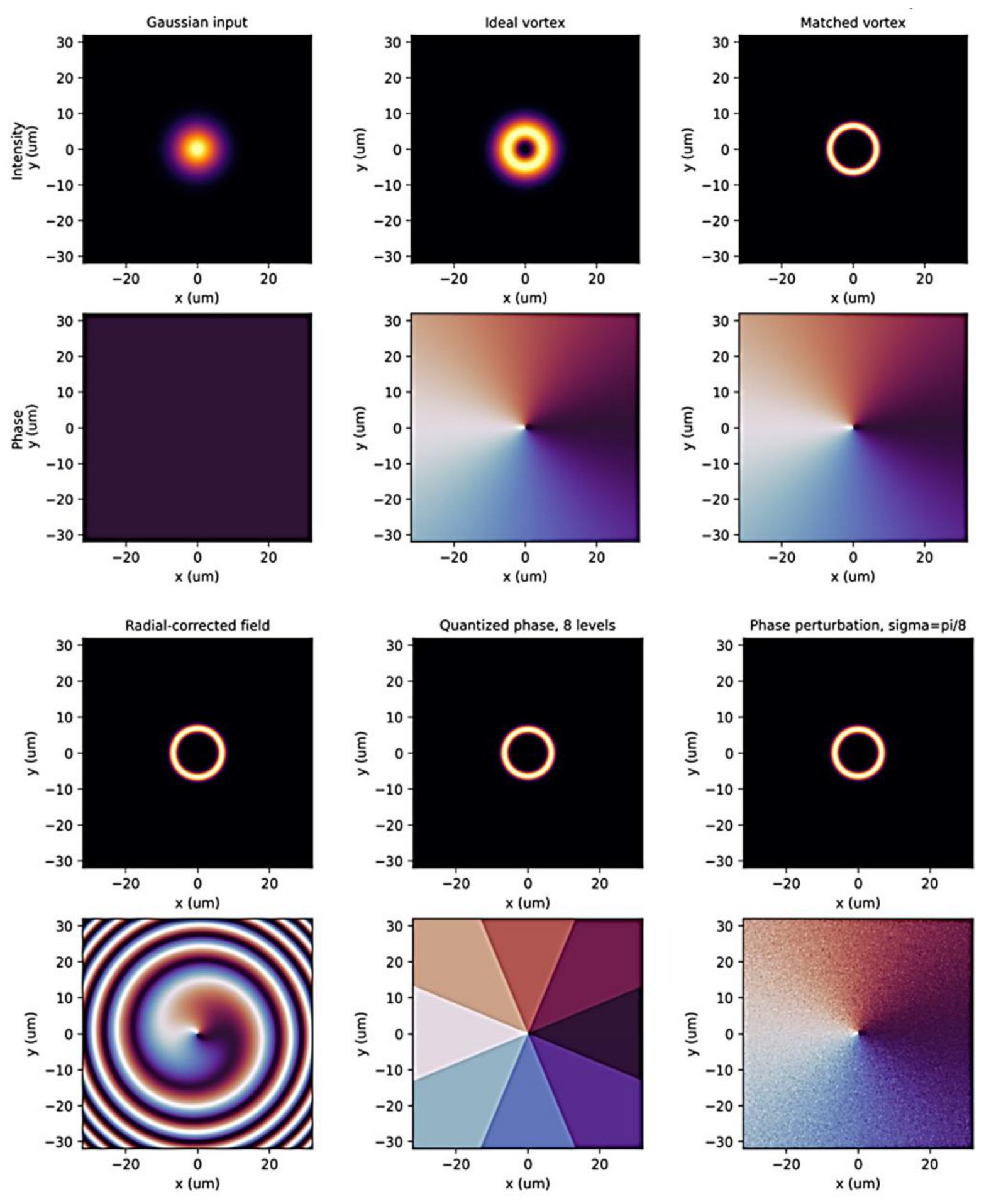
The matched vortex field provides the ideal reference case. In this case, the field is constructed to reproduce the radial envelope and azimuthal phase dependence of the selected target mode. It therefore represents the upper limit of coupling performance within the scalar modal basis. The radial-corrected field approximates this condition more realistically: it preserves the required vortex phase structure while improving the radial localization of the optical power in the target annular region. This comparison is important because it shows that the role of the metasurface is not limited to imposing the phase factor . Instead, the metasurface must also prepare the radial amplitude distribution and spatial scale required for efficient modal excitation.
The quantized and phase-perturbed fields represent practical deviations from the ideal field. The quantized phase case models a metasurface with finite phase resolution, here using eight discrete phase levels. The phase-perturbed case models random phase errors with standard deviation . These two cases allow one to distinguish between deterministic phase discretization and random phase degradation. Both effects reduce the coherent projection onto the target mode, but their influence on modal purity and crosstalk can be different.
6.2. Coupling Efficiency and Modal Selectivity
The main coupling metrics are summarized in Table 3 and Figure S2. The ideal vortex field gives a target-mode coupling efficiency of 0.616, corresponding to an insertion loss of 2.10 dB. Its modal purity is 0.922, while its OAM-state purity is 1.000. This result is central to the interpretation of the whole study. It shows that the input field can carry the correct azimuthal order and still fail to excite the target guided mode efficiently. In other words, the topological charge is necessary for vortex-compatible excitation, but it is not sufficient for full modal selectivity.
Figure 3.
Coupling efficiency and purity metrics for different simulated input fields. The bar chart compares the target-mode coupling efficiency, modal purity, and OAM-state purity for five input-field cases: ideal vortex, matched vortex, radial-corrected field, eight-level quantized phase field, and phase-perturbed field with . The ideal vortex field preserves the required OAM-state purity but provides limited target-mode coupling because its radial profile is not fully matched to the target ring-core guided mode. The matched vortex represents the ideal scalar modal-matching limit. The radial-corrected and quantized phase fields retain high target-mode coupling, showing that radial modal matching is more important than simple vortex-phase generation. The phase-perturbed case demonstrates the reduction of coherent coupling caused by random phase errors while maintaining high modal and OAM-state purity within the scalar modal basis.
Figure 3.
Coupling efficiency and purity metrics for different simulated input fields. The bar chart compares the target-mode coupling efficiency, modal purity, and OAM-state purity for five input-field cases: ideal vortex, matched vortex, radial-corrected field, eight-level quantized phase field, and phase-perturbed field with . The ideal vortex field preserves the required OAM-state purity but provides limited target-mode coupling because its radial profile is not fully matched to the target ring-core guided mode. The matched vortex represents the ideal scalar modal-matching limit. The radial-corrected and quantized phase fields retain high target-mode coupling, showing that radial modal matching is more important than simple vortex-phase generation. The phase-perturbed case demonstrates the reduction of coherent coupling caused by random phase errors while maintaining high modal and OAM-state purity within the scalar modal basis.
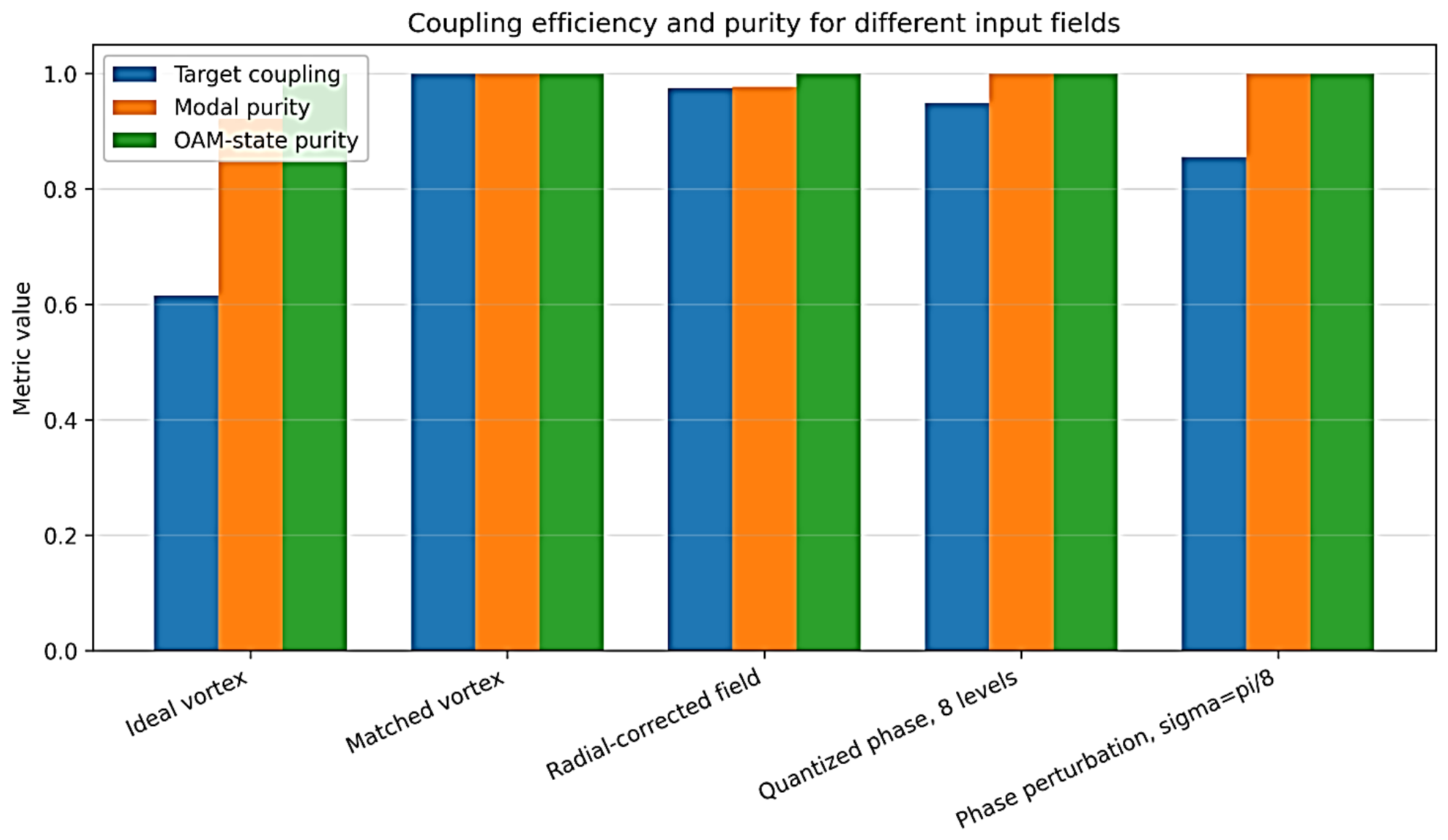
The matched vortex field reaches the ideal scalar limit, with target-mode coupling efficiency equal to 1.000, modal purity equal to 1.000, and OAM-state purity equal to 1.000. The corresponding crosstalk values are at the numerical floor of the orthonormalized modal basis and should not be interpreted as physically meaningful attenuation values. This case is used only as a benchmark showing the best possible result when the incident field exactly reproduces the target modal structure.
The numerical values reported in Table 5 should be interpreted as scalar modal-overlap estimates rather than as direct experimental efficiencies of a fabricated metasurface–fiber system. Nevertheless, the observed trend is consistent with previous studies of OAM coupling into ring-core fibers, where the coupling efficiency was shown to depend strongly on the radial structure and OAM order of the incident beam [11]. In particular, overlap-based analyses indicate that conventional Laguerre–Gaussian beams are not always optimal for coupling into ring-core fibers, whereas vortex fields with better radial matching can approach nearly ideal coupling under suitable conditions [11]. Experimental and numerical studies of ring-core fiber systems further show that practical performance is limited by polarization effects, modal coupling, fiber perturbations, fabrication imperfections, and crosstalk between neighboring mode groups [12,13,23,24]. Therefore, the present results should be viewed as a design-scale modal-matching benchmark that quantifies the potential benefit of metasurface-assisted radial and phase matching before full vectorial, propagation, and experimental effects are included.
The radial-corrected field demonstrates the main practical advantage of metasurface-assisted modal matching. Its target-mode coupling efficiency reaches 0.975, and the insertion loss decreases to 0.11 dB. The modal purity is 0.978, and the OAM-state purity remains 1.000. Compared with the ideal vortex field, the target-mode coupling increases from 61.6% to 97.5%. This confirms that radial matching is the dominant mechanism responsible for improving selective excitation of the vortex-compatible guided mode.
The quantized phase case with eight phase levels still gives high target-mode coupling efficiency, 0.950, with an insertion loss of 0.22 dB. In the present scalar basis, the modal purity and OAM-state purity remain close to unity. This indicates that moderate phase discretization mainly reduces the coherent projection onto the target field rather than strongly transferring power into the competing guided modes included in the basis. This result is encouraging for practical metasurface implementation, since real metasurfaces usually provide phase control through a finite set of meta-atom geometries rather than a perfectly continuous phase profile.
The phase-perturbed field with gives a lower target-mode coupling efficiency of 0.856 and an insertion loss of 0.68 dB. However, the modal purity remains very high, approximately 0.9999. This means that the random phase perturbation in this scalar model reduces the coherent overlap with the target mode, but does not strongly project the field onto the competing guided modes included in the modal basis. Therefore, phase noise should be interpreted primarily as a coherent-overlap loss mechanism in this simplified model, although a full vectorial and device-specific model may reveal additional scattering or polarization-dependent coupling channels.
Overall, these results show that OAM-state purity alone is not a sufficient metric for evaluating coupling into ring-core fiber modes. Several field cases preserve the desired azimuthal order, but differ strongly in target-mode coupling efficiency and modal purity. The useful performance of the coupling interface is therefore determined by the full complex-field overlap with the selected guided mode, including radial structure, phase profile, polarization compatibility, and alignment.
6.3. Mode-Resolved Interpretation of Parasitic Coupling
The mode-resolved spectra in Figures S3 and S4 clarify why the ideal vortex field does not provide optimal coupling. For the ideal vortex field, the dominant contribution is still the target mode , with overlap power 0.616. However, non-negligible parasitic contributions appear in other modes with the same azimuthal order . The largest of these are associated with modes localized in neighboring radial or annular regions, including and . This explains why the OAM-state purity can remain equal to 1.000 while the modal purity and target-mode coupling are lower.
This observation is physically important. A simple vortex beam can be topologically correct but radially mismatched. It may carry the required phase winding, yet still distribute part of its power among modes with different radial order or ring localization. Therefore, a coupling scheme based only on generating a vortex phase cannot guarantee selective excitation of the desired guided state.
Figure 4.
Dominant guided-mode overlaps for the ideal vortex input field. The bar chart shows the largest modal-overlap powers obtained when the input field is a simple ideal vortex beam with the correct azimuthal order. The dominant contribution corresponds to the target mode , but additional non-negligible power is coupled into modes with the same azimuthal order and different radial or annular localization, such as and . This result demonstrates that a free-space vortex field can be topologically correct while still being radially mismatched to the selected ring-core guided mode. Therefore, the correct OAM order alone is not sufficient for selective excitation of the target vortex-compatible mode.
Figure 4.
Dominant guided-mode overlaps for the ideal vortex input field. The bar chart shows the largest modal-overlap powers obtained when the input field is a simple ideal vortex beam with the correct azimuthal order. The dominant contribution corresponds to the target mode , but additional non-negligible power is coupled into modes with the same azimuthal order and different radial or annular localization, such as and . This result demonstrates that a free-space vortex field can be topologically correct while still being radially mismatched to the selected ring-core guided mode. Therefore, the correct OAM order alone is not sufficient for selective excitation of the target vortex-compatible mode.
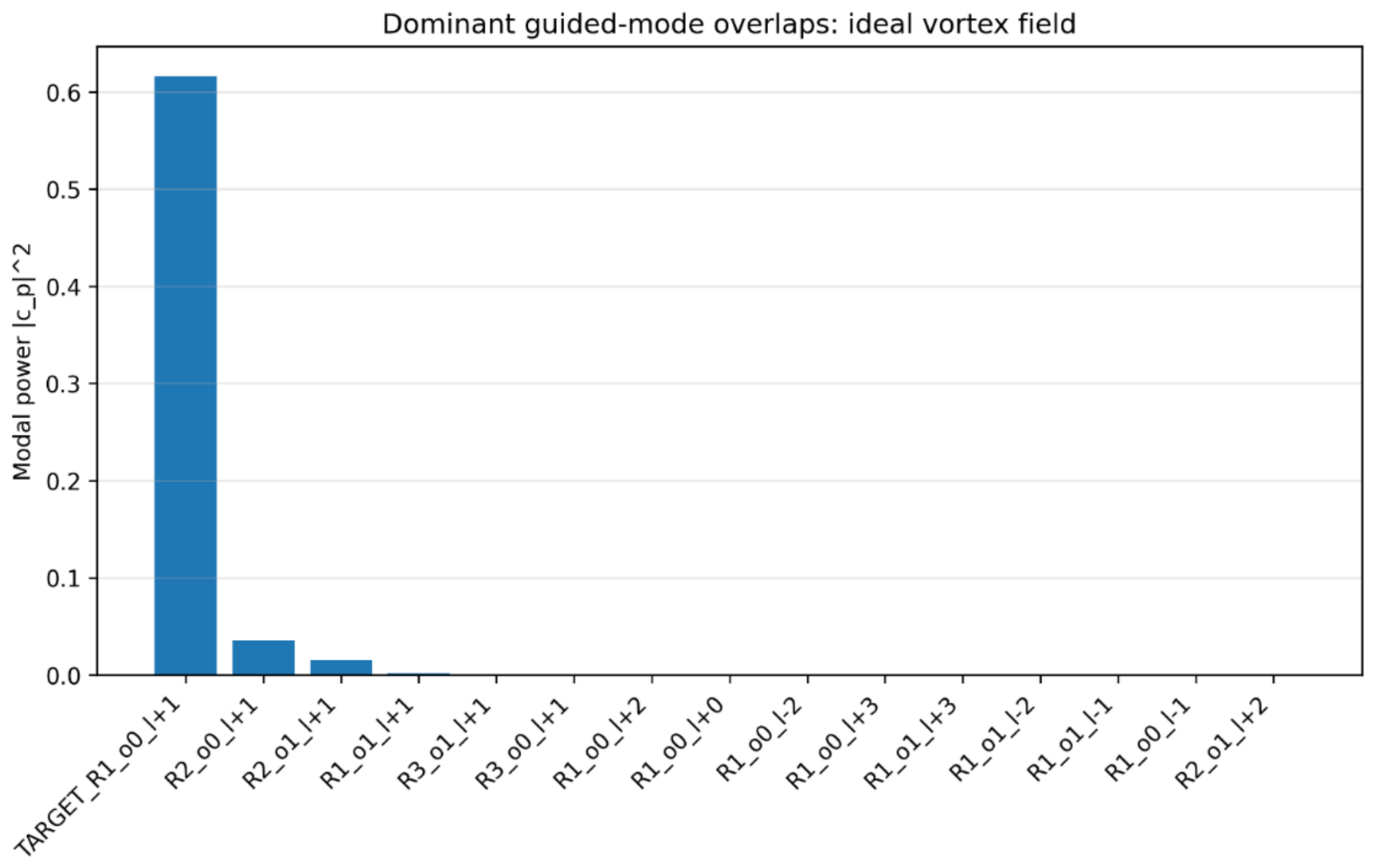
Figure 5.
Dominant guided-mode overlaps for the matched vortex input field. The bar chart shows the modal-overlap powers ) obtained for the matched vortex field. In this reference case, the input field is constructed to reproduce the radial envelope and azimuthal phase structure of the target guided mode . As a result, almost all modal power is concentrated in the target mode, while the projections onto competing radial, azimuthal, or neighboring-ring modes are negligible within the numerical accuracy of the scalar modal basis. This case represents the ideal modal-matching limit and serves as a benchmark for evaluating the performance of the radial-corrected, quantized, and phase-perturbed input fields.
Figure 5.
Dominant guided-mode overlaps for the matched vortex input field. The bar chart shows the modal-overlap powers ) obtained for the matched vortex field. In this reference case, the input field is constructed to reproduce the radial envelope and azimuthal phase structure of the target guided mode . As a result, almost all modal power is concentrated in the target mode, while the projections onto competing radial, azimuthal, or neighboring-ring modes are negligible within the numerical accuracy of the scalar modal basis. This case represents the ideal modal-matching limit and serves as a benchmark for evaluating the performance of the radial-corrected, quantized, and phase-perturbed input fields.
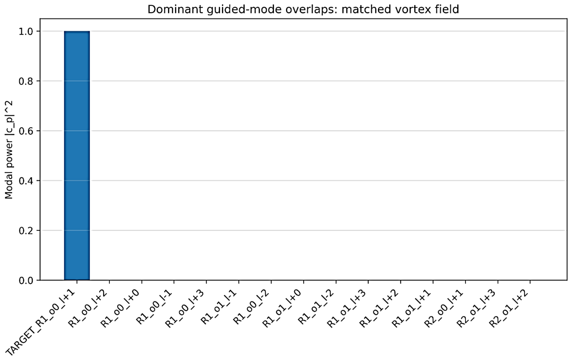
In contrast, the matched vortex field concentrates essentially all modal power in the target mode within the numerical accuracy of the scalar basis. The comparison between Figures S3 and S4 therefore demonstrates the difference between topological matching and complete modal matching. Topological matching selects the azimuthal order, whereas complete modal matching selects the full guided mode, including radial localization.
The radial-corrected field bridges these two cases. It preserves the desired azimuthal phase order while reshaping the radial distribution to match the annular guided mode more closely. The resulting suppression of other-ring leakage, from approximately −10.9 dB for the ideal vortex field to −53.5 dB for the radial-corrected field, confirms that radial field engineering is essential for multi-ring-core architectures. In such systems, undesired excitation of neighboring annular regions can occur even when the topological charge is correct. The metasurface should therefore be regarded as a modal-matching interface rather than only as a vortex generator.
These results support the main physical conclusion of the study: efficient excitation of vortex-compatible guided modes in ring-core and multi-ring-core fibers requires simultaneous control of azimuthal phase and radial modal structure. The annular geometry of the fiber provides a natural platform for vortex-like states, but the input field must still be matched to the actual guided eigenmode supported by the structure.
6.4. Tolerance Analysis and Metrological Limits
The tolerance analysis evaluates how the ideal modal-matching condition degrades when practical perturbations are introduced. In contrast to the comparison of field-generation cases in Section 6.2, the tolerance study starts from the matched vortex field and then applies controlled deviations. This approach makes it possible to identify which experimental parameters are most critical for maintaining high target-mode coupling and modal purity.
The strongest degradation is observed for lateral displacement. When the input field is shifted by 0.25 µm relative to the fiber axis, the target-mode coupling efficiency remains high, eta_target = 0.988. At 0.5 µm displacement, decreases to 0.955, and modal purity remains 0.956. These values indicate that submicrometer alignment errors can still be tolerated in the present scalar model. However, at 1.0 µm displacement, decreases to 0.833 and modal purity decreases to 0.849. At 2.0 µm displacement, falls to 0.502, and the insertion loss increases to 2.99 dB. This behavior is expected because a transverse displacement simultaneously shifts the annular intensity maximum and the vortex phase singularity away from the center of the ring-core geometry. Therefore, lateral alignment is one of the most critical practical tolerances for metasurface-assisted excitation of vortex-compatible modes.
Angular tilt has a much weaker influence over the tested range. For tilt values up to 2 mrad, the target-mode coupling efficiency remains above 0.998, and the insertion loss remains below 0.01 dB. This indicates that, in the present scalar and paraxial model, small angular deviations mainly introduce a weak transverse phase gradient that does not strongly destroy the overlap with the target mode. However, this result should not be overgeneralized. In a real system, angular tilt may also modify the focal position, numerical aperture matching, and polarization-dependent coupling. Therefore, angular tolerance should be interpreted as model-dependent and should be re-evaluated in a full vectorial design.
Defocus also produces only minor degradation in the tested range. For axial defocus values between −20 µm and +20 µm, the target-mode coupling efficiency remains above 0.9999. This weak sensitivity reflects the simplified scalar propagation model and the relatively broad axial tolerance of the assumed field at the input plane. In an experimental system, defocus may become more important when high numerical aperture focusing, finite metasurface aperture, or nonparaxial field components are included. Nevertheless, within the present model, defocus is not the dominant limitation compared with lateral displacement, waist mismatch, or ring-radius mismatch.
Beam-waist mismatch has a significantly stronger effect. A −5% waist mismatch gives = 0.959, while a +5% mismatch gives = 0.963. Thus, small waist errors of about 5% are acceptable. At −10%, however, eta_target decreases to 0.839, and at +10% it decreases to 0.866. For ±20% mismatch, the degradation becomes severe: is 0.460 for −20% and 0.593 for +20%. This confirms that the radial scale of the generated annular field must be matched to the radial localization of the guided mode. A field that is too narrow or too wide can still carry the correct azimuthal phase order, but it no longer reproduces the target radial modal envelope.
Ring-radius mismatch is another critical tolerance. A mismatch of ±0.5 µm still gives ≈ 0.918, with modal purity ≈ 0.921. At ±1 µm, eta_target decreases to approximately 0.71, and modal purity decreases to approximately 0.745. At ±2 µm, drops to about 0.25–0.26. This result is particularly important for ring-core and multi-ring-core fibers because the useful field is confined to a narrow annular region. The generated annular beam must therefore match not only the topological charge of the mode, but also the radial position of the guiding ring. In the present model, maintaining the ring-radius error below approximately 0.5 µm is required for high-efficiency coupling.
Phase noise produces a gradual reduction of target-mode coupling. For remains 0.962, and the insertion loss is 0.17 dB. At /8, decreases to 0.857, with insertion loss of 0.67 dB. At , decreases further to 0.541, corresponding to insertion loss of 2.67 dB. At the same time, modal purity remains close to unity over the tested range. This means that random phase errors primarily reduce the coherent projection onto the target field rather than transferring a large fraction of power into the competing guided modes included in the scalar modal basis. For practical metasurface design, this result indicates that phase errors below approximately are desirable if coupling efficiency above 90% is required.
Finite phase quantization also affects the coherent target-mode projection. With four phase levels, is 0.811 and insertion loss is 0.91 dB. With eight phase levels, increases to 0.950, and the insertion loss decreases to 0.22 dB. Sixteen phase levels further improve to 0.987, while 32 and 64 levels approach the continuous-phase limit. Thus, in the present model, an eight-level phase profile is already sufficient to exceed 90% target-mode coupling, while 16 or more levels provide a more comfortable margin. This supports the feasibility of metasurface-based implementation, where the phase profile is usually realized through a finite set of meta-atom geometries.
Polarization mismatch follows the expected overlap trend. A mismatch of 5° gives = 0.992, and a 10° mismatch gives = 0.970. At 20°, decreases to 0.883, while at 45° only half of the target-mode power remains. This indicates that polarization control is not negligible, especially if the target guided mode has vectorial or spin–orbit structure. In the present scalar-corrected model, polarization mismatch is treated through a uniform overlap factor. A more complete treatment would require spatially dependent vectorial overlap between the metasurface-generated field and the actual hybrid vector mode of the ring-core fiber.
Taken together, the tolerance results identify the dominant practical limitations of the proposed coupling scheme. Lateral displacement, beam-waist mismatch, ring-radius mismatch, phase noise, and polarization mismatch are the most critical parameters. Angular tilt and defocus are less important in the present scalar model and over the tested ranges, but they should not be neglected in a full experimental design. From a metrological point of view, the most important practical requirement is that the generated annular field must remain centered, radially scaled, phase-stable, and polarization-compatible with the target guided mode.
The tolerance thresholds should be interpreted as discrete estimates obtained from the simulated sweep values rather than as exact continuous limits. For the present model, maintaining above 90% requires approximately: lateral displacement below 0.5 µm, ring-radius mismatch below 0.5 µm, beam-waist mismatch within about ±5%, phase noise below , and polarization mismatch below about 10°. For phase quantization, eight phase levels are sufficient to exceed 90% target-mode coupling, while 16 or more levels are preferable for low insertion loss. These values define the approximate alignment and fabrication requirements for an experimental metasurface-assisted coupling system.
6.5. Design Implications and Limitations
The numerical results lead to several design implications. First, the annular geometry of the ring-core fiber is useful only if the input field is matched to the actual guided mode. A simple vortex beam may carry the correct topological charge, but it can still excite several modes with the same azimuthal order and different radial localization. This is why OAM-state purity alone is not sufficient for evaluating the performance of the coupling interface.
Second, radial field engineering is the key advantage of the metasurface-assisted approach. The comparison between the ideal vortex field and the radial-corrected field shows that target-mode coupling can be increased from 0.616 to 0.975 when the radial structure of the incident field is matched to the target annular mode. This improvement is much larger than the degradation caused by moderate phase quantization. Therefore, metasurface design should prioritize full modal matching rather than only the generation of a helical phase profile.
Third, multi-ring-core geometries require additional control of radial-channel selectivity. In such fibers, a beam with the correct topological charge may still leak into modes localized in neighboring annular regions. The reduction of other-ring leakage from −10.9 dB in the ideal vortex case to −53.5 dB in the radial-corrected case shows that radial matching can strongly suppress unintended excitation of adjacent rings. This point is particularly important for future mode-division multiplexing or radial-channel architectures.
Fourth, the tolerance results show that the proposed coupling system is experimentally demanding but not unrealistic. The required submicrometer lateral alignment and submicrometer radial matching are comparable to the tolerances encountered in precision fiber coupling and integrated-photonics packaging. The phase quantization result is also favorable, because an eight-level or sixteen-level metasurface phase profile is more realistic than an ideal continuous phase mask. However, polarization control and mechanical stability remain important issues for future experiments.
The present study has several limitations. The model is scalar and uses an analytical modal basis rather than a full vectorial eigenmode solver for a fabricated ring-core fiber. Therefore, the numerical values should be interpreted as proof-of-principle estimates and design-scale indicators rather than final device specifications. The real modal spectrum of a fabricated fiber may include hybrid vector modes, polarization splitting, degeneracy lifting, bending-induced coupling, and spin–orbit effects that are not fully captured here. The calculated crosstalk values near the numerical floor should also not be interpreted as experimentally measurable suppression levels.
Another limitation is that long-distance propagation is not analyzed. The present work focuses on the input plane and evaluates how efficiently the metasurface-generated field projects onto the selected guided mode. Once the mode is excited, its stability over distance will depend on the actual fiber geometry, bending radius, ellipticity, refractive-index perturbations, mechanical stress, and modal effective-index separation. These effects require a propagation model or experimental verification and are left for future work.
Despite these limitations, the results support the main conclusion of the paper: metasurface-assisted coupling should be formulated as a modal-matching problem rather than as a vortex-generation problem. A practical input interface must match the target guided mode in radial amplitude, azimuthal phase, polarization, spatial scale, and alignment. When these conditions are satisfied, the coupling efficiency and modal purity can be substantially improved compared with a simple free-space vortex beam. This provides a quantitative basis for designing compact structured-light interfaces for ring-core and multi-ring-core fiber photonic systems.
7. Conclusions
This work developed a modal-overlap framework for metasurface-assisted coupling of vortex optical states into ring-core and multi-ring-core fiber architectures. The central idea is that efficient excitation of vortex-compatible guided modes cannot be reduced to the generation of a free-space vortex beam with a prescribed topological charge. Instead, the incident field must be matched to the selected guided mode in its radial intensity profile, azimuthal phase structure, polarization state, spatial scale, numerical aperture, and alignment at the fiber input facet.
The numerical results demonstrate the difference between topological matching and full modal matching. A simple vortex field carrying the correct azimuthal order gives perfect OAM-state purity in the scalar modal basis, but only 0.616 target-mode coupling efficiency and an insertion loss of 2.10 dB. This confirms that the correct topological charge alone is not sufficient for selective excitation of the target ring-core mode. After radial modal matching, the target-mode coupling increases to 0.975, while the insertion loss decreases to 0.11 dB. The other-ring leakage is also strongly suppressed, demonstrating the importance of radial field engineering in ring-core and multi-ring-core geometries.
The tolerance analysis identifies the main practical requirements for experimental implementation. The most critical perturbations are lateral displacement, beam-waist mismatch, ring-radius mismatch, phase noise, finite phase quantization, and polarization mismatch. In the present scalar model, maintaining target-mode coupling above approximately 90% requires submicrometer lateral and radial alignment, waist matching within several percent, phase errors below approximately , and polarization mismatch below about 10 degrees. At the same time, the results indicate that eight phase levels can already provide high coupling efficiency, while sixteen or more phase levels give a larger practical margin.
The proposed approach therefore shifts the design objective from vortex generation to guided-mode excitation. In this interpretation, the metasurface acts as a compact modal-matching interface between a conventional incident beam and a selected vortex-compatible mode of a structured fiber. This is particularly important for multi-ring-core architectures, where a field with the correct azimuthal order may still excite neighboring radial channels if its annular intensity profile is not properly matched.
The present study is intentionally limited to the input-coupling and modal-matching problem. The model is scalar and uses an analytical modal basis; therefore, the numerical values should be interpreted as proof-of-principle estimates and design-scale indicators rather than final specifications of a fabricated fiber–metasurface system. A full vectorial eigenmode calculation, fabricated-fiber parameters, propagation modeling, bending analysis, and experimental verification will be required for device-level optimization.
Despite these limitations, the results support the main conclusion that metasurface-assisted modal matching provides a systematic route toward efficient and reproducible excitation of vortex-compatible guided modes in ring-core and multi-ring-core fiber systems. The developed metrics—target-mode coupling efficiency, modal purity, OAM-state purity, crosstalk, insertion loss, and tolerance limits—form a practical basis for designing structured-light input interfaces for future fiber photonic architectures.
Supplementary Materials
The following supporting information can be downloaded at the website of this paper posted on Preprints.org.
References
- Allen, L.; Beijersbergen, M.W.; Spreeuw, R.J.C.; Woerdman, J.P. Orbital angular momentum of light and the transformation of Laguerre-Gaussian laser modes. Phys. Rev. A 1992, 45, 8185–8189. [Google Scholar] [CrossRef] [PubMed]
- Yao, A.M.; Padgett, M.J. Orbital angular momentum: Origins, behavior and applications. Adv. Opt. Photonics 2011, 3, 161–204. [Google Scholar] [CrossRef]
- Willner, A.E.; Huang, H.; Yan, Y.; Ren, Y.; Ahmed, N.; Xie, G.; Bao, C.; Li, L.; Cao, Y.; Zhao, Z.; et al. Optical communications using orbital angular momentum beams. Adv. Opt. Photonics 2015, 7, 66–106. [Google Scholar] [CrossRef]
- Richardson, D.J.; Fini, J.M.; Nelson, L.E. Space-division multiplexing in optical fibres. Nat. Photonics 2013, 7, 354–362. [Google Scholar] [CrossRef]
- Bozinovic, N.; Yue, Y.; Ren, Y.; Tur, M.; Kristensen, P.; Huang, H.; Willner, A.E.; Ramachandran, S. Terabit-scale orbital angular momentum mode division multiplexing in fibers. Science 2013, 340, 1545–1548. [Google Scholar] [CrossRef] [PubMed]
- Brunet, C.; Rusch, L.A. Optical fibers for the transmission of orbital angular momentum modes. Opt. Fiber Technol. 2017, 35, 2–7. [Google Scholar] [CrossRef]
- Zhang, Z.; Gan, J.; Heng, X.; Wu, Y.; Li, Q.; Qian, Q.; Chen, D.; Yang, Z. Optical fiber design with orbital angular momentum light purity higher than 99.9%. Opt. Express 2015, 23, 29331–29341. [Google Scholar] [CrossRef] [PubMed]
- Nejad, R.M.; Allahverdyan, K.; Vaity, P.; Amiralizadeh, S.; Brunet, C.; Messaddeq, Y.; LaRochelle, S.; Rusch, L.A. Mode division multiplexing using orbital angular momentum modes over 1.4-km ring core fiber. J. Light. Technol. 2016, 34, 4252–4258. [Google Scholar] [CrossRef]
- Zhang, J.; Zhu, G.; Liu, J.; Wu, X.; Zhu, J.; Du, C.; Luo, W.; Yu, S. Orbital-angular-momentum mode-group multiplexed transmission over a graded-index ring-core fiber based on receive diversity and maximal ratio combining. Opt. Express 2018, 26, 4243–4257. [Google Scholar] [CrossRef] [PubMed]
- Zhu, G.; Hu, Z.; Wu, X.; Du, C.; Luo, W.; Chen, Y.; Liu, X.; Zhang, J.; Zhu, J.; Wang, A.; et al. Scalable mode division multiplexed transmission over a 10-km ring-core fiber using high-order orbital angular momentum modes. Opt. Express 2018, 26, 594–604. [Google Scholar] [CrossRef] [PubMed]
- Rojas-Rojas, S.; Cañas, G.; Saavedra, G.; Gómez, E.; Walborn, S.P.; Lima, G. Evaluating the coupling efficiency of OAM beams into ring-core optical fibers. Opt. Express 2021, 29, 23381–23392. [Google Scholar] [CrossRef] [PubMed]
- Liu, Y.-S.; Wang, Y.; Geng, W.; Zhao, W.; Zhang, H.; Zhang, W.; Pan, Z.; Yue, Y. Parabolic-index ring-core fiber supporting high-purity orbital angular momentum modes. Sensors 2023, 23, 3641. [Google Scholar] [CrossRef] [PubMed]
- Wu, G.; Gao, S.; Tu, J.; Shen, L.; Feng, Y.; Sui, Q.; Liu, W.; Li, Z. Mode manipulation in a ring-core fiber for OAM monitoring and conversion. Nanophotonics 2022, 11, 4889–4898. [Google Scholar] [CrossRef] [PubMed]
- Yu, N.; Capasso, F. Flat optics with designer metasurfaces. Nat. Mater. 2014, 13, 139–150. [Google Scholar] [CrossRef] [PubMed]
- Arbabi, A.; Horie, Y.; Bagheri, M.; Faraon, A. Dielectric metasurfaces for complete control of phase and polarization with subwavelength spatial resolution and high transmission. Nat. Nanotechnol. 2015, 10, 937–943. [Google Scholar] [CrossRef] [PubMed]
- Khorasaninejad, M.; Chen, W.T.; Devlin, R.C.; Oh, J.; Zhu, A.Y.; Capasso, F. Metalenses at visible wavelengths: Diffraction-limited focusing and subwavelength resolution imaging. Science 2016, 352, 1190–1194. [Google Scholar] [CrossRef] [PubMed]
- Kamali, S.M.; Arbabi, E.; Arbabi, A.; Faraon, A. A review of dielectric optical metasurfaces for wavefront control. Nanophotonics 2018, 7, 1041–1068. [Google Scholar] [CrossRef]
- Chen, M.L.N.; Jiang, L.J.; Sha, W.E.I. Orbital angular momentum generation and detection by geometric-phase based metasurfaces. Appl. Sci. 2018, 8, 362. [Google Scholar] [CrossRef]
- Overvig, A.C.; Shrestha, S.; Malek, S.C.; Lu, M.; Stein, A.; Zheng, C.; Yu, N. Dielectric metasurfaces for complete and independent control of the optical amplitude and phase. Light Sci. Appl. 2019, 8, 92. [Google Scholar] [CrossRef] [PubMed]
- Ahmed, H.; Intaravanne, Y.; Ming, Y.; Ansari, M.A.; Buller, G.S.; Zentgraf, T.; Chen, X. Optical metasurfaces for generating and manipulating optical vortex beams. Nanophotonics 2022, 11, 941–956. [Google Scholar] [CrossRef] [PubMed]
- Xie, J.; Guo, H.; Zhuang, S.; Hu, J. Polarization-controllable perfect vortex beam by a dielectric metasurface. Opt. Express 2021, 29, 3081–3090. [Google Scholar] [CrossRef] [PubMed]
- Yang, N.; Zhang, X.; Yu, X.; Zhou, J.; Zhang, L. Ring-core fiber-based coupling and amplification of OAM modes: Realizing efficient second-to-first and second-to-second order mode conversion. Opt. Express 2025, 33, 13010–13021. [Google Scholar] [CrossRef] [PubMed]
- Banawan, M.; Wang, L.; LaRochelle, S.; Rusch, L.A. Quantifying the coupling and degeneracy of OAM modes in high-index-contrast ring core fiber. J. Light. Technol. 2021, 39, 600–611. [Google Scholar] [CrossRef]
- Guerra, G.; Lonardi, M.; Galtarossa, A.; Rusch, L.A.; Bononi, A.; Palmieri, L. Analysis of modal coupling due to birefringence and ellipticity in strongly guiding ring-core OAM fibers. Opt. Express 2019, 27, 8308–8326. [Google Scholar] [CrossRef] [PubMed]
Figure 1.
Geometry of ring-core and multi-ring-core fiber architectures and a target vortex-like guided mode. (a) Cross-section of a single ring-core fiber with an annular guiding region defined by the inner radius , outer radius , ring width , and refractive-index contrast . The lower inset shows the corresponding idealized radial refractive-index profile . (b) Cross-section of a multi-ring-core fiber containing several concentric annular guiding regions. Each ring is characterized by its own inner and outer radii, width, and radial position. The inset illustrates a simplified multi-step radial refractive-index profile. (c) Schematic representation of a target vortex-like guided mode with annular intensity distribution and azimuthal phase dependence , where is the topological charge.
Figure 1.
Geometry of ring-core and multi-ring-core fiber architectures and a target vortex-like guided mode. (a) Cross-section of a single ring-core fiber with an annular guiding region defined by the inner radius , outer radius , ring width , and refractive-index contrast . The lower inset shows the corresponding idealized radial refractive-index profile . (b) Cross-section of a multi-ring-core fiber containing several concentric annular guiding regions. Each ring is characterized by its own inner and outer radii, width, and radial position. The inset illustrates a simplified multi-step radial refractive-index profile. (c) Schematic representation of a target vortex-like guided mode with annular intensity distribution and azimuthal phase dependence , where is the topological charge.
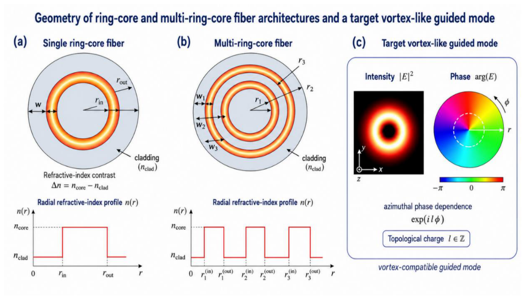

Table 1.
Baseline parameters.
| Parameter | Symbol | Baseline Value | Comment |
|---|---|---|---|
| Operating wavelength | λ | 1550 nm | Reference wavelength for modeling |
| Cladding refractive index | 1.444 | Silica-based cladding approximation | |
| Annular core refractive index | 1.450 | Step-index annular core | |
| Index contrast | 0.006 | − | |
| Numerical aperture | ≈0.132 | Estimated from core and cladding indices | |
| Cladding radius | 62.5 µm | Standard fiber radius | |
| Single-ring inner radius | 5 µm | Inner boundary of annular core | |
| Single-ring outer radius | 8 µm | Outer boundary of annular core | |
| Ring width | 3 µm | − | |
| Number of rings | 1, 2, or 3 | Single- and multi-ring cases | |
| Inter-ring gap | 2–8 µm | Used in parametric sweep |
Table 2.
Target-mode set used in the simulations.
| Target case | Symbolic Field Form | Main Purpose |
|---|---|---|
| Fundamental ring-like mode | Reference case for radial matching without vortex phase | |
| Vortex mode, = 1 | Baseline OAM-like guided state | |
| Vortex mode, = 2 | Higher-order vortex-compatible excitation | |
| Ring-selected vortex mode | Selective excitation of a chosen annular channel | |
| Vector vortex mode | Optional case including polarization structure |
Table 3.
Complete set of simulated metasurface-generated fields.
| Field Case | Field Type | Purpose |
|---|---|---|
| Ideal vortex field | Reference case: correct topological charge without radial modal matching | |
| Matched vortex field | Ideal target field approximating the guided-mode envelope | |
| Phase-corrected field | Realistic phase-only metasurface with focusing and radial correction | |
| Quantized phase field | Evaluation of finite phase-level implementation | |
| Perturbed phase field | Evaluation of fabrication-like phase errors and robustness |
Table 4.
Representative tolerance-study plan for metasurface-assisted coupling into ring-core and multi-ring-core fiber modes.
Table 4.
Representative tolerance-study plan for metasurface-assisted coupling into ring-core and multi-ring-core fiber modes.
| Perturbation | Symbol | Representative Sweep | Main Expected Effect |
|---|---|---|---|
| Lateral displacement | 0–2 µm | Reduced radial and phase-center matching | |
| Angular tilt | 0–2 mrad | Additional transverse phase gradient | |
| Defocus | ±2 to ±20 µm | Incorrect waist and wavefront curvature at fiber facet | |
| Beam-waist mismatch | ±10–20% | Incorrect radial scaling of generated field | |
| Ring-radius mismatch | 0–2 µm | Mismatch between annular field and guided-mode radius | |
| Phase noise | 0 to (\pi/4) | Reduced phase fidelity and increased crosstalk | |
| Phase quantization | 4, 8, 16, 32, continuous | Diffraction artifacts and reduced modal purity | |
| Polarization mismatch | 0–45° | Reduced vector overlap and polarization crosstalk |
Table 5.
Numerical estimates of coupling efficiency, modal purity, crosstalk, and insertion loss for the simulated input-field cases.
Table 5.
Numerical estimates of coupling efficiency, modal purity, crosstalk, and insertion loss for the simulated input-field cases.
| Input Field | Guided Power | Modal Purity | OAM-State Purity | Max. Crosstalk (dB) | Insertion Loss (dB) |
Other-Ring Leakage (dB) |
|
|---|---|---|---|---|---|---|---|
| Ideal vortex | 0.616 | 0.668 | 0.922 | 1.000 | −12.44 | 2.10 | −10.90 |
| Matched vortex | 1.000 | 1.000 | 1.000 | 1.000 | <numerical floor | 0.00 | <numerical floor |
| Radial-corrected field | 0.975 | 0.997 | 0.978 | 1.000 | −16.42 | 0.11 | −53.54 |
| Quantized phase, 8 levels | 0.950 | 0.950 | 1.000 | 1.000 | −144.16 | 0.22 | −180.86 |
| Phase perturbation, σ = π/8 | 0.856 | 0.856 | 0.9999 | 0.9999 | −45.75 | 0.68 | −82.55 |
Note: The values are obtained from numerical modal-overlap calculations and are rounded to the number of digits shown for comparison between the simulated cases. They should be interpreted as model-based estimates rather than experimentally measured values. Very low crosstalk and leakage values below approximately −100 dB indicate the numerical floor of the scalar modal basis and should not be interpreted as experimentally guaranteed suppression levels.
Disclaimer/Publisher’s Note: The statements, opinions and data contained in all publications are solely those of the individual author(s) and contributor(s) and not of MDPI and/or the editor(s). MDPI and/or the editor(s) disclaim responsibility for any injury to people or property resulting from any ideas, methods, instructions or products referred to in the content. |
© 2026 by the authors. Licensee MDPI, Basel, Switzerland. This article is an open access article distributed under the terms and conditions of the Creative Commons Attribution (CC BY) license (http://creativecommons.org/licenses/by/4.0/).
Copyright: This open access article is published under a Creative Commons CC BY 4.0 license, which permit the free download, distribution, and reuse, provided that the author and preprint are cited in any reuse.


