

Submitted:
25 June 2026
Posted:
25 June 2026
You are already at the latest version
Abstract
Traditional elastic shell theory relies heavily on cumbersome tensor calculus in curvilinear coordinates and is usually confined to a small-deformation linear framework. This not only obscures intrinsic physical and geometric meanings but also makes theoretical derivations under large deformations extremely arduous. This paper systematically constructs a geometrically exact (finite deformation) Kirchhoff-Love shell dynamic theory based on modern differential geometry—specifically fiber bundle theory and differential forms—while retaining linear constitutive relations. We model the elastic shell as a fiber bundle with the mid-surface as the base manifold and the thickness interval as the fiber. By employing Cartan’s method of moving frames, we replace traditional Christoffel symbols with sparse antisymmetric connection 1-forms, thereby completely avoiding the algebraic disaster caused by coordinates. In kinematics, by introducing a nonlinear deformation mapping and a pull-back metric, we define the Green-Lagrange strain tensor, which naturally decomposes into geometrically exact membrane and bending strains, ensuring no spurious strains arise under large rotations. In dynamics, based on the Second Piola-Kirchhoff (PK2) stress, we define a vector-valued stress 2-form and adopt the principle of virtual work as the core statement of global equilibrium. Through integration along the normal fiber, the three-dimensional principle of virtual work is naturally and coordinate-independently reduced to a two-dimensional one on the mid-surface, where complex geometric nonlinear coupling terms automatically emerge through the exterior derivative structure. Finally, the Saint-Venant-Kirchhoff linear constitutive model is introduced to close the system of equations. This theory explicitly targets ”large rotation, small strain” conditions, revealing the profound meaning of geometric nonlinearity and laying a rigorous theoretical foundation for engineering structures such as flexible electronics and post-buckling of thin plates.
Keywords:
geometrically exact Kirchhoff-Love shell
; fiber bundle theory
; differential forms
; large rotation small strain
; virtual work principle
; elastic shell dynamic theory
1. Introduction
1.1. Historical Evolution and Geometric Awakening of Shell Theory
The mathematical theory of elastic shells is one of the oldest, most complex, and most physically captivating branches of continuum mechanics. Fundamentally, shell mechanics deals with how to reduce three-dimensional elastic equations to a two-dimensional surface, while preserving the additional stiffness and complex geometric coupling effects brought about by the curvature of the surface. The history of this field is a history of constant struggle against coordinate complexity, culminating in a geometric awakening.
The foundation of modern shell theory can be traced back to the mid-19th century. In 1850, Gustav Kirchhoff proposed two fundamental assumptions when studying elastic plates: the hypothesis of normal preservation (normals to the mid-surface before deformation remain normal and unstretched after deformation) and the hypothesis of negligible transverse normal stress [1]. These assumptions effectively reduced the number of unknown fields, allowing the three-dimensional elastic equations to be integrated through the thickness. Subsequently, Augustus Edward Hough Love extended this framework to surfaces with initial curvature in 1888, forming the renowned Kirchhoff-Love shell theory [2]. For much of the 20th century, this theory dominated civil, aerospace, and ship engineering. Scholars such as Love, Flügge [3], Novozhilov [5], Goldenveizer [6], and Kraus [4] derived extremely complex equations of motion in general curvilinear coordinate systems.
However, classical derivations face serious mathematical obstacles. In a general curvilinear coordinate system , the metric tensor of the shell depends explicitly on the thickness coordinate z. To derive equilibrium equations, one must calculate the covariant derivative of the stress tensor , which requires introducing up to 18 independent Christoffel symbols of the second kind . The expressions for these symbols are extremely lengthy and filled with nonlinear terms. When reducing the three-dimensional equilibrium equations via integration, a large number of cumbersome partial integrations and index contractions are involved. As pointed out by Green and Zerna [7], this coordinate-dependent derivation not only obscures the physical and geometric significance behind the equations but is also prone to algebraic errors. To simplify calculations, engineers have had to rely on special coordinate systems (such as lines of curvature coordinates), which compromises the universality of the theory.
In the 1970s, continuum mechanics underwent a profound paradigm shift. Élie Cartan’s method of moving frames [8] was introduced into mechanics. Cartan pointed out that by choosing a local orthonormal basis, the matrix of connection 1-forms is antisymmetric (), which immediately halves the number of independent connection components. More importantly, exterior differential forms (including the exterior derivative , wedge product ∧, and interior product ) provide a completely coordinate-free calculus tool. Misner, Thorne, and Wheeler [9] demonstrated the powerful utility of these tools in general relativity. In the field of mechanics, Marsden and Hughes’ pioneering work Mathematical Foundations of Elasticity [10] systematically reformulated nonlinear elasticity using manifolds, tangent bundles, and Lie derivatives. They proved that the strain tensor is essentially the perturbation of the displacement flow on the Riemannian metric, and that equilibrium laws can be rigorously established via variational principles in a coordinate-free framework. Epstein [11] further extended these ideas to material defects and non-Euclidean elasticity, using principal bundles and connections to characterize the geometric structure of continua.
In recent years, important breakthroughs have been made in geometric methods based on Cartan’s moving frame method combined with Finite Element Exterior Calculus (FEEC). Dhas, N, Roy, and Reddy (2022) [23] systematically introduced Cartan’s moving frames into the mixed variational principle of nonlinear elasticity for the first time, interpreting physical quantities such as stress and deformation gradient as differential forms, and achieving geometrically exact discretization using FEEC. Subsequently, Jamun Kumar et al. extended this framework to Kirchhoff rods (2022) [24] and Kirchhoff shells (2024) [25], successfully constructing locking-free continuous finite element schemes by introducing independent orthogonal frame fields and the Hu-Washizu functional. Meanwhile, Rashad et al. (2023) [26] provided a unified exterior calculus formulation for intrinsic nonlinear elasticity starting from bundle-valued differential forms, revealing the principal bundle and de Rham complex structures underlying the theory. These advances indicate that combining fiber bundles, differential forms, and FEEC is a powerful tool for developing the next generation of geometrically exact, coordinate-free, and high-precision shell elements. This paper systematically constructs a geometrically exact shell dynamic theory based on fiber bundles and differential forms against this background, laying a foundation for subsequent numerical implementation.
1.2. The Necessity of Geometrically Exact Theory
With the development of modern engineering and physics, classical small-deformation linear shell theory can no longer meet demands. In fields such as flexible electronics [18], soft robotics, cell membrane mechanics [19], and nanomaterials (e.g., graphene [20]), shell structures often undergo large displacements and rigid body rotations, even though their intrinsic strains may remain small. Under these "large rotation, small strain" conditions, if linear kinematics are adopted, ignoring higher-order rotation terms, the structure will produce non-physical "spurious strains" under pure rigid body rotation, leading to completely erroneous stress calculations and numerical divergence.
To address this issue, Simo and Fox [14,30] proposed the "Geometrically Exact Shell Theory" in 1989. This theory retains full nonlinearity in kinematics, accurately describing arbitrarily large displacements and rotations, ensuring the invariance of rigid body motion. Subsequently, extensive research has been dedicated to embedding geometrically exact theory into finite element computations [14,15,30]. However, traditional geometrically exact theories are still mostly built within the framework of matrix vectors and tensor indices. For shells with complex initial curvature and non-Euclidean effects, index notation remains cumbersome.
In the development of the aforementioned geometrically exact shell theory, the seminal contributions of Simo and Fox (1989) and their subsequent work (particularly Fox’s doctoral dissertation [29,30]) laid the foundation. They refined shell kinematics into a combination of the mid-surface position vector and a director field vector by introducing the single-director field variable pair , thereby completely avoiding explicit operations of covariant derivatives and Christoffel symbols at the kinematic level; all field quantities are handled directly in vector space. This framework, due to its great simplicity and natural compatibility with finite element discretization, has become an important cornerstone of modern nonlinear shell numerical analysis.
However, although Simo-Fox’s "no complex geometry" framework is computationally convenient, it largely "implicitizes" the curvature and torsion deformation information of the surface into the gradient of the director field . While efficient, this treatment makes the coordinate-independence of the theory less explicit and difficult to directly generalize to cases with non-trivial topology or non-Euclidean reference metrics (e.g., growth, defect-induced residual stress).
The starting point of this paper is complementary to the aforementioned classic work: we do not shy away from geometry but actively make it explicit. Specifically, we reintroduce Cartan’s moving frames, connection 1-forms on fiber bundles, and exterior differential operations. Although this choice introduces more abstract mathematical structures, it brings three irreplaceable advantages: (1) All physical quantities (strains, stresses) are interpreted as differential forms, and their integral and differential essence (e.g., Stokes’ theorem) is precisely retained; (2) The antisymmetry of connection 1-forms minimizes independent variables and automatically degenerates to classical results in the thin-shell limit; (3) The theory is naturally compatible with Finite Element Exterior Calculus (FEEC), providing a direct path for constructing locking-free, structure-preserving continuous shell elements. Therefore, this paper can be viewed as a geometric explicitation and deep structural supplement to the Simo-Fox classic framework.
Combining fiber bundle theory, exterior differential forms, and geometrically exact kinematics is the natural trend of current geometric mechanics development. A shell is essentially a fiber bundle structure where a three-dimensional manifold reduces to a two-dimensional manifold, with the thickness direction being the fiber. Viewing the dimensional reduction process as integration along the fiber, realized via generalized Stokes’ theorem and exterior covariant derivatives, maximizes the maintenance of the theory’s coordinate-independence and automatically reveals the geometric origin of curvature coupling terms [13,16].
1.3. Motivation and Contributions of This Paper
Although the work of Marsden-Hughes and Simo-Fox has laid a solid foundation, literature that starts from fiber bundles and differential forms to derive a complete geometrically exact Kirchhoff-Love shell theory and elaborate on its nonlinear dynamic coupling mechanisms in detail remains scarce and scattered. This paper aims to systematically construct this theoretical framework. Our core objective is to extend kinematics to finite deformation (geometric nonlinearity) to accurately capture large rotation effects, while retaining linear constitutive relations (Saint-Venant-Kirchhoff model) at the material level. This combination of "geometric nonlinearity + material linearity" explicitly targets "large rotation, small strain" conditions and is extremely applicable to the engineering analysis of most hard materials and flexible electronic devices.
The specific contributions of this paper are as follows:
- Fiber Bundle Geometry of the Reference Configuration: The reference shell is modeled as a fiber bundle with the mid-surface as the base. Through Cartan’s first structure equation, antisymmetric connection 1-forms are derived, encoding all geometric information in the lines-of-curvature coordinate system with minimal algebraic cost, and the Gauss-Codazzi equations are naturally recovered through the vanishing of the curvature 2-form.
- Nonlinear Kinematics Based on Pull-Back Metric: Abandoning the linearized Lie derivative, we introduce a nonlinear deformation mapping from the reference manifold to the current spatial configuration. Using the pull-back metric , we define the Green-Lagrange strain tensor and precisely separate nonlinear membrane and bending strains. Since the pull-back metric is used, the theory strictly produces zero strain under pure large rigid body rotation, eliminating the "spurious strains" in linear theory.
- Virtual Work Principle and Exterior Covariant Dynamics: In the Lagrangian description, we employ the second Piola-Kirchhoff (PK2) stress conjugate to the Green-Lagrange strain energy and formulate it as a vector-valued stress 2-form. The PK2 stress is designed for finite deformation and remains directionally invariant under rigid body rotation, ensuring the objectivity of the theory. Through the principle of virtual work, local equilibrium is transformed into a global variational statement of internal virtual work equaling external virtual work.
- Integration Along Fibers and Nonlinear Dimensional Reduction: We demonstrate in detail how to reduce the three-dimensional virtual work principle to the two-dimensional mid-surface through integration along the normal fiber. Nonlinear geometric coupling terms (e.g., the coupling of normal rotation and membrane forces, i.e., the geometric stiffness effect) naturally emerge through the variation of virtual strains and the use of exterior differential properties, without cumbersome coordinate expansion.
- Linear Constitutive Closure: The linear constitutive relation between stress and strain is retained. Since it is defined on the reference configuration, this "linear" relation still satisfies frame-invariance, making the entire theory suitable for large rotation problems while maintaining geometric nonlinearity.
2. Geometric Foundations of the Reference Configuration
To establish a geometrically exact shell theory, we must first lay a solid geometric foundation in the reference configuration. We will not rely on specific coordinate system choices but view the shell as a differentiable manifold equipped with specific metrics and connections.
2.1. Fiber Bundle Structure of the Shell Manifold
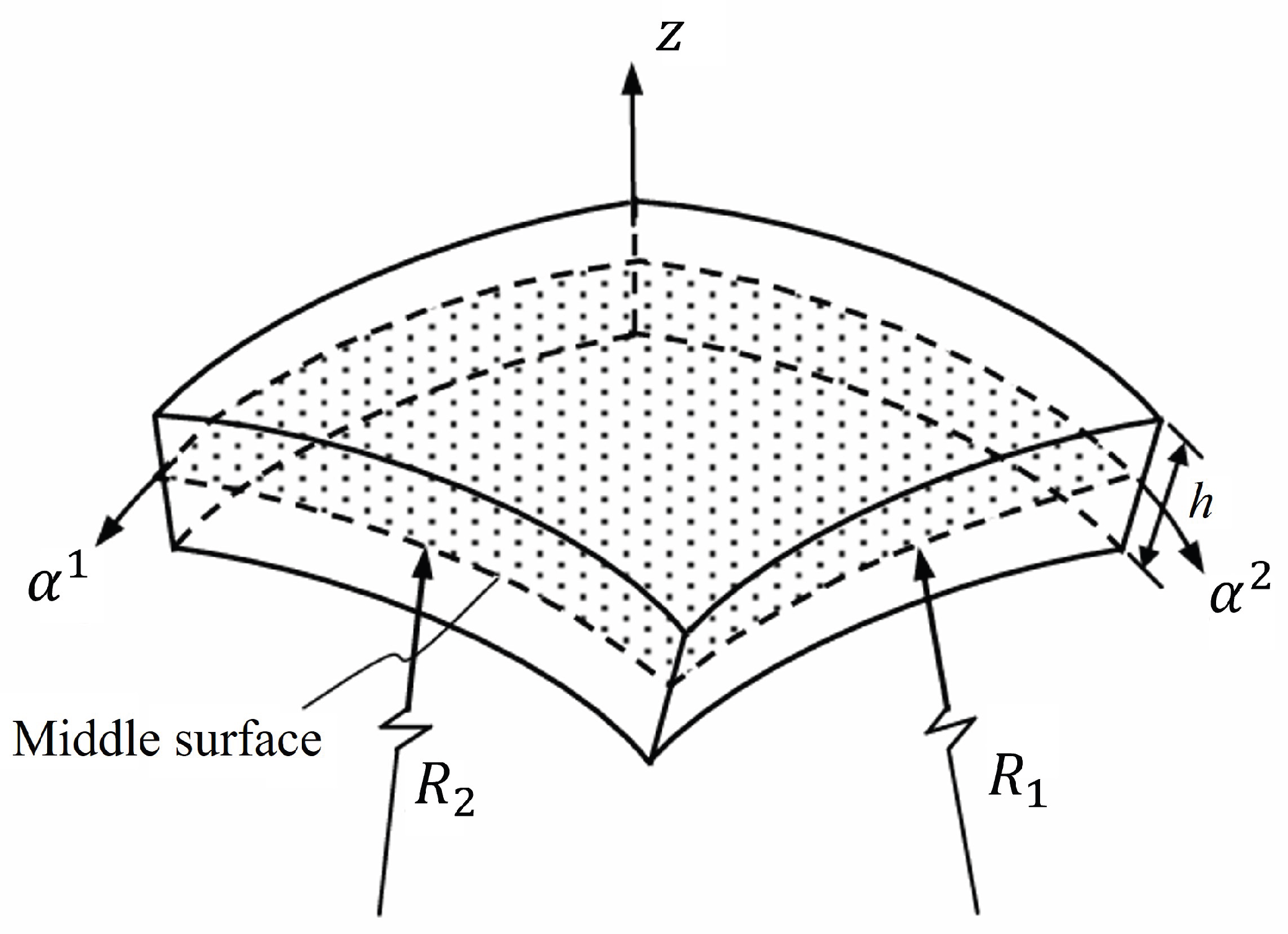
Let be the undeformed reference configuration of the elastic shell, a three-dimensional smooth manifold with boundary. We endow with a locally trivial fiber bundle structure, denoted as , where is a two-dimensional smooth, orientable Riemannian manifold representing the mid-surface of the shell; is the bundle projection. For any point , its preimage is a one-dimensional fiber representing the normal thickness interval at point p, where (L is the characteristic length of the mid-surface). The shell element is illustrated in Figure 1.
The tangent bundle naturally splits into a direct sum of horizontal and vertical sub-bundles: . The horizontal sub-bundle is isomorphic to the pull-back bundle , containing vectors tangent to surfaces of constant thickness; the vertical sub-bundle is spanned by the normal vector field .
To parameterize the manifold, we introduce a local coordinate chart on . By the fundamental theorem of surfaces, as long as the principal curvatures are unequal, we can always choose lines of curvature coordinates [12]. In this case, the coordinate lines coincide with the principal curvature directions. Let and be the principal radii of curvature, and the third coordinate z be taken along the unit normal vector of the mid-surface. Thus, the local coordinates on are .
2.2. Reference Metric and Orthogonal Moving Frame
The geometric properties of the reference manifold are determined by its Riemannian metric . Consider a point on the manifold at a distance z from the mid-surface along the normal. In the principal direction a, the distance from this point to the corresponding center of curvature is . The infinitesimal arc length is , where is the infinitesimal angle subtended at the center of curvature, and is the Lamé parameter of the mid-surface. Therefore, the reference metric tensor is:
This metric depends explicitly on z, reflecting the physical fact that parallel surfaces have different intrinsic metrics. Traditional methods would proceed to calculate the inverse metric and 18 Christoffel symbols . To avoid this coordinate disaster, we adopt Cartan’s method of moving frames [8,17].
Instead of using the coordinate co-frame , we construct an orthogonal co-frame by observing equation (1):
In this basis, the metric takes the standard Euclidean form:
The dual moving frame (tangent basis) is and . The reference volume form is:
where is the area change factor due to normal displacement. The Hodge star operator acts very simply in this orthogonal basis; for example, .
2.3. Connection 1-Forms and Cartan’s First Structure Equation
The connectivity of the manifold is encoded in the connection 1-forms . Since we have chosen an orthogonal frame, the connection is metric-compatible (), meaning the connection matrix is antisymmetric: . This property directly reduces the number of independent connection components from 18 to 3. Assuming a torsion-free connection (the hypothesis of no dislocations in standard continuum mechanics), Cartan’s first structure equation uniquely determines the connection:
To solve for , we apply the exterior derivative to :
Through algebraic simplification and replacing the coordinate basis back to the orthogonal basis , after careful index matching, we can extract the non-zero connection 1-forms from (5). The components related to normal curvature are:
This represents the bending of the normal vector towards the center of curvature as one moves along the surface. The connection 1-form for in-plane rotation is:
These two simple 1-forms completely replace the lengthy Christoffel symbol expressions in classical tensor calculus. The covariant derivatives of vector fields and differential forms are now simplified to the exterior derivative plus the wedge product with these sparse 1-forms.
2.4. Curvature Constraints and Mid-Surface Geometry
Since the reference configuration is isometrically embedded in flat Euclidean space , its intrinsic Riemannian curvature must be zero. According to Cartan’s second structure equation:
Substituting equations (8) and (9) into this identity imposes strict differential constraints, namely the famous Gauss-Codazzi-Mainardi equations. For example, calculating and projecting to the mid-surface yields the Codazzi equation . Calculating yields the Gauss equation, where the Gaussian curvature is completely determined by the intrinsic metric. In our geometric framework, these are not added assumptions but necessary consequences of the flatness of the ambient space.
The geometry of the mid-surface is induced by the pull-back of the inclusion mapping at . The mid-surface co-frame is . The first fundamental form is , and the second fundamental form is . The intrinsic connection on the mid-surface is , which completely determines the Levi-Civita covariant derivative on the mid-surface. Since the frame is orthogonal, the connection coefficients are antisymmetric in the first two indices, which is the key to avoiding massive algebraic cancellation in the moving frame method.
3. Finite Deformation Kinematics and Pull-Back Metric
Classical shell theory usually defines strain as the Lie derivative of the displacement vector field with respect to the reference metric under the small deformation assumption. However, when the structure undergoes large displacements or rotations, this linearization generates spurious strains. To establish a geometrically exact theory, we must abandon the linear expansion of the displacement field and instead directly operate on the global nonlinear deformation mapping. This kinematic nonlinearity is the core distinction between this theory and classical linear theory.
3.1. Nonlinear Deformation Mapping and Kirchhoff-Love Constraint
Let the deformation mapping from the reference configuration to the current spatial configuration be . The Kirchhoff-Love hypothesis requires that normals to the mid-surface before deformation remain normal and unstretched after deformation. This means the deformation of the shell is completely determined by the mapping of the mid-surface and the unit normal vector field of the current mid-surface :
Here, the normal vector is no longer a small rotation approximation of the reference normal , but an independent kinematic variable on the tangent bundle, taking values in the unit sphere fiber bundle. Since must be perpendicular to the deformed mid-surface, it must satisfy the orthogonality constraint:
The set of kinematic variables can accurately describe arbitrarily large rigid body translations and rotations. Under pure rigid body rotation , , , and the form of the mapping remains invariant, ensuring the objectivity of the theory.
3.2. Pull-Back Metric and Green-Lagrange Strain
In the geometrically nonlinear framework, the strain measure cannot be calculated directly through the spatial metric on the current configuration; it must be pulled back to the reference configuration to eliminate the influence of rigid body motion. Let be the Euclidean metric of . The pull-back metric is a second-order covariant tensor defined on the reference manifold , physically known as the right Cauchy-Green deformation tensor.
The Green-Lagrange strain tensor is defined as half the difference between the pull-back metric and the reference metric:
Since both and are defined on the reference configuration, is also a tensor on the reference configuration. Under pure rigid body motion, , and thus , which excludes spurious strains by definition.
Remark (Note on Not Explicitly Using the Deformation Gradient Tensor). In classical continuum mechanics, the deformation gradient tensor is usually a core physical quantity. However, in the geometrically exact framework of this paper, we do not explicitly use for three reasons: First, the right Cauchy-Green deformation tensor is essentially the inner product of the deformation gradient (). By directly introducing the pull-back metric and differentiating the deformation mapping when calculating its components , we have implicitly and completely retained all information of the deformation gradient. Second, the direct expansion based on the Kirchhoff-Love kinematic variables naturally derives membrane and bending strains, skipping the step of explicitly constructing the deformation gradient matrix, which greatly simplifies algebraic operations. Third, the component representation of the deformation gradient tensor depends highly on the choice of coordinate basis. This paper aims to build a coordinate-independent theory using moving frames and differential forms. Using the pull-back metric to replace the deformation gradient matrix maximizes the preservation of the geometric covariance and objectivity of the theory, reflecting the core philosophy of modern geometric mechanics (e.g., the Marsden-Hughes framework).
3.3. Thickness Expansion and Nonlinear Strain Separation
To reduce the three-dimensional strain, we need to calculate the components of the pull-back metric and expand them along the thickness z. From (11), the tangential components of the pull-back metric are:
We define the first fundamental form and the second fundamental form of the current mid-surface:
Neglecting higher-order terms in (the standard practice in thin shell approximation, corresponding to ignoring normal stress effects in the thickness direction), the pull-back metric can be compactly represented as:
Simultaneously, the expansion of the reference metric is . Substituting into the strain definition (13), we obtain:
This naturally separates the Green-Lagrange strain into a zero-order membrane strain and a first-order bending strain :
This derivation is purely geometric and nonlinear. precisely measures the stretching and shearing of the mid-surface due to deformation, while precisely measures the true change in curvature. Even if the mid-surface is not stretched (), non-zero bending strain will arise as long as the curvature changes ().
4. Dynamics Based on the Principle of Virtual Work
Since the kinematics are completely nonlinear, traditional direct force balance derivations become extremely complex due to the expansion of nonlinear terms. In the Lagrangian description, establishing dynamic equations through the principle of virtual work is the most rigorous approach that naturally preserves objectivity.
4.1. Stress 2-Forms on the Reference Configuration
To be energy-conjugate to the Green-Lagrange strain , we adopt the second Piola-Kirchhoff (PK2) stress tensor . Unlike the Cauchy stress, PK2 stress is defined on the reference configuration and does not change direction with rigid body rotation. In finite deformation mechanics, PK2 stress is a stress measure specifically designed for the Lagrangian description; it ensures that the stress-strain relationship on the reference configuration remains objective regardless of how large the rotation the structure undergoes. This makes it extremely convenient for handling large rotation problems.
In the language of modern differential geometry, we do not view stress as a second-order tensor but as a vector-valued stress 2-form defined on the reference manifold :
Here, is a 2-form representing the directed area element orthogonal to the basis vector . The stress 2-form intrinsically represents the flux of force through that area element in the direction. The Hodge star operator automatically handles the orientation of the surface, avoiding the complex normal vector cross-products in tensor index methods.
4.2. Principle of Virtual Work
The equilibrium of the system is governed by the principle of virtual work: for any kinematically admissible virtual displacement , the internal virtual work equals the external virtual work plus the inertial virtual work. On the reference configuration, the three-dimensional principle of virtual work is expressed as:
where is the variation of the Green-Lagrange strain, is the body force per unit mass, is the prescribed surface traction on the Neumann boundary , is the reference density, and is the acceleration. Equation (23) is completely coordinate-independent and implicitly implies conservation of linear and angular momentum.
4.3. Variation of Virtual Strain and Nonlinear Geometric Coupling
To reduce the equation dimension, we need to calculate the virtual strain . Since and the reference metric is invariant, the virtual strain is the variation of the pull-back metric:
The variation of the deformation mapping is . Through algebraic operations, it can be shown that the virtual strain can also be expanded in thickness:
The explicit expressions for membrane virtual strain and bending virtual strain are:
The most critical geometric feature here is that the virtual strain depends not only on the mid-surface variation but also highly on the variation of the normal vector field . Due to the orthogonality constraint (12), must be perpendicular to , i.e., . Thus, is actually an infinitesimal rotation vector. This intertwining of and is the core distinction between geometrically nonlinear theory and linear theory. In the virtual work integral, will generate coupling terms between membrane forces and normal rotation, which cannot be captured by classical linear theory.
5. Integration Along Fibers and Dimensional Reduction Dynamics
The core of shell theory lies in dimensional reduction. We integrate the three-dimensional virtual work equation (23) along the normal fiber z.
5.1. Reduction of Internal Virtual Work
Substituting into the internal virtual work integral and using the reference volume form , we have:
We define the membrane force tensor and moment tensor based on the PK2 stress :
Since and depend only on mid-surface coordinates (independent of z), the integral can be separated directly. The internal virtual work simplifies to:
This is the internal part of the nonlinear principle of virtual work on the two-dimensional mid-surface.
5.2. Reduction of External and Inertial Forces
Similarly, integrating the body force along the thickness yields the equivalent area force and equivalent area moment on the mid-surface:
The reduction of the acceleration term requires utilizing the kinematics , thus . Neglecting higher-order small quantities of rotational inertia (order ), the inertial virtual work reduces to:
5.3. Nonlinear Principle of Virtual Work on the Mid-Surface
Synthesizing the above results, the geometrically exact nonlinear principle of virtual work on the reference mid-surface is stated as: find such that for all kinematically admissible variations , the following holds:
5.4. Emergence of Strong Form and Nonlinear Equilibrium Equations
By expanding and in equation (35), and utilizing the covariant derivative on the mid-surface and partial integration (i.e., using Stokes’ theorem in exterior calculus), we can extract the local strong form equilibrium equations. Since the variations and are arbitrary within the domain (except for the constraint ), we obtain: Linear Momentum Balance:
Angular Momentum Balance:
Normal Balance (Core of Nonlinear Coupling):
Here, is the transverse shear force. The key lies in the nonlinear term in the third equation. Since is precisely the second fundamental form of the current mid-surface, this term represents the coupling of membrane forces with the current curvature (i.e., geometric stiffness). It is this nonlinear term that allows the structure to exhibit real nonlinear behaviors such as "stress stiffening" or "stress softening" under large rotations. In our geometric framework, this complex nonlinear term naturally emerges from the term contained in the virtual strain variation , without relying on specific coordinate expansion, completely preserving tensor covariance.
6. Linear Constitutive Relations and System Closure
To close the system, we need to establish constitutive relations between stress and strain. As mentioned earlier, this paper focuses on engineering problems of large rotation and small strain, so we retain the linear elastic hypothesis of the material.
6.1. Objectivity of Saint-Venant-Kirchhoff Material
The Saint-Venant-Kirchhoff constitutive model assumes that the PK2 stress is proportional to the Green-Lagrange strain . Since both quantities are defined on the reference configuration, they are invariant under pure rigid body rotation. Therefore, this "linear" relationship is actually objective and will not produce non-physical stresses due to large rotations. This allows us to safely use linear constitutive relations without undermining the overall geometric nonlinearity of the theory.
For isotropic materials, on the tangential plane of the reference mid-surface, the constitutive relation is:
where is the fourth-order isotropic elasticity tensor on the reference mid-surface:
where E is Young’s modulus and is Poisson’s ratio.
6.2. Reduced Constitutive Equations
Substituting the strain expansion into the constitutive equation (39) and combining the definitions of membrane force and moment, integration along the thickness yields:
For thin shells, we approximate . Since and are independent of z, and the integral , membrane and bending terms decouple. Defining the extensional stiffness and bending stiffness , we obtain the two-dimensional constitutive equations:
Although the constitutive relation is linear in form, since and contain the nonlinear deformation mapping and normal , the final relationship between force and deformation is highly nonlinear. These equations, together with the preceding nonlinear equilibrium equations and the kinematic constraint (12), constitute a closed geometrically exact Kirchhoff-Love shell theory.
7. Conclusions and Outlook
This paper systematically constructs a geometrically exact elastic shell dynamic theory based on fiber bundles and differential forms. By viewing the shell as a fiber bundle on the reference manifold, we utilize Cartan’s method of moving frames to greatly simplify the geometric description, replacing lengthy Christoffel symbols with antisymmetric connection 1-forms. In kinematics, we introduce a nonlinear deformation mapping and define the Green-Lagrange strain through the pull-back metric, precisely separating nonlinear membrane and bending strains, completely eliminating spurious strains under large rotations. In dynamics, by adopting a vector-valued stress 2-form based on PK2 stress, we take the principle of virtual work as the core and naturally reduce it to the mid-surface through integration along the normal fiber. Complex geometric nonlinear coupling terms (such as the interaction of membrane forces with current curvature) automatically emerge during the variational process and fully preserve coordinate-independence. Finally, linear Saint-Venant-Kirchhoff constitutive relations are retained, making the theory explicitly applicable to engineering structures with large rotations and small strains.
It is worth emphasizing that the geometric framework constructed in this paper is completely equivalent in physical substance to the single-director model of Simo-Fox (1989). When we degenerate the Cartan co-frame in this paper to a coordinate basis and explicitly substitute the connection 1-forms into the strain expressions, the membrane, bending, and shear strain components in classical literature can be accurately recovered. The difference between the two lies only in the language of formulation: the classical framework "hides" geometry within vector derivatives, while this paper makes it "explicit" as algebraic operations of differential forms. Although this explicitness adds to the initial abstraction, it provides a unified mathematical platform for subsequent structure-preserving discretization, multi-field coupling (e.g., piezoelectric, thermo-mechanical), and non-Euclidean geometry extensions. Therefore, this work is not a negation of the classics but a deep excavation and formal enhancement of their geometric content.
The theoretical framework of this paper is entirely based on exterior differentiation and differential forms, which gives it a natural affinity with Discrete Exterior Calculus (DEC) or Finite Element Exterior Calculus (FEEC) [27,28]. By directly mapping the continuous theory to piecewise polynomial differential form spaces, efficient numerical algorithms that preserve geometric structures and avoid locking (especially shear and membrane locking) can be constructed. Existing work [23,24,25] has successfully implemented discretization based on mixed variational principles and FEEC, demonstrating excellent numerical performance. Therefore, the theory in this paper lays a solid continuous foundation for developing the next generation of geometrically exact, structure-preserving shell elements.
This geometric framework is not only an elegant rewrite of classical nonlinear shell theory but also opens broad avenues for future research. First, since the entire derivation is based on exterior differentiation, the theory can be directly mapped into the Discrete Exterior Calculus (DEC) framework [22], thereby developing structure-preserving finite element algorithms that naturally avoid shear locking and membrane locking. Second, by modifying the reference metric to have non-zero Riemann curvature, the theory can be seamlessly extended to non-Euclidean elasticity [21] to describe residual stresses caused by growth, thermal expansion, or defects. These will be the focus of our future work.
Author Contributions
B.H. Sun: Conceptualization, Investigation, Formal analysis, Formulations, Data curation, Writing-original draft, Writing-review & editing, Visualization.
Funding
The authors declare that no specific funding was received for this study.
Data Availability Statement
No data were generated or analyzed in this study.
Acknowledgments
My research into shell theory started at Lanzhou University and Ruhr-Universität Bochum, with core work completed during my tenure as a professor at the Cape Peninsula University of Technology (CPUT), South Africa. I am profoundly grateful to CPUT for granting me the unrestricted academic autonomy to pursue this research agenda—this vital institutional support laid the groundwork for the principal conclusions presented in this manuscript. I extend my most sincere thanks to former Vice-Chancellor (now Chancellor) Prof. Brian Figaji, as well as former Deputy Vice-Chancellors Prof. J. A. Tromp and Prof. Anthony Staak, for their generous endorsement. Further academic support was provided by Xi’an University of Architecture and Technology (XAUAT) and the Beijing Institute of Nanoenergy and Nanosystems (BINN), Chinese Academy of Sciences. I sincerely thank former XAUAT President Prof. Xiao-Jun Liu and current President Prof. Xiang-Mo Zhao, along with BINN Founding Director Prof. Zhong Lin Wang, for their unwavering encouragement and invaluable resource support throughout this study.
Conflicts of Interest
The author declares that he has no known competing financial interests or personal relationships that could have appeared to influence the work reported in this paper.
References
- G. Kirchhoff, “Über das Gleichgewicht und die Bewegung einer elastischen Scheibe,” Journal für die reine und angewandte Mathematik, vol. 40, pp. 51–88, 1850. [CrossRef]
- A. E. H. Love, A Treatise on the Mathematical Theory of Elasticity. Dover Publications, 1944.
- W. Flügge, Tensor Analysis and Continuum Mechanics. Springer-Verlag, 1972.
- H. Kraus, Thin Elastic Shells. John Wiley & Sons, 1967.
- V. V. Novozhilov, Thin Shell Theory. Noordhoff, 1959.
- A. L. Goldenveizer, Theory of Elastic Thin Shells. Pergamon Press, 1961.
- A. E. Green and W. Zerna, Theoretical Elasticity. Oxford University Press, 1968.
- É. Cartan, La théorie des groupes finis et continus et la géométrie différentielle traitée par la méthode du repère mobile. Gauthier-Villars, 1937.
- C. W. Misner, K. S. Thorne, and J. A. Wheeler, Gravitation. W. H. Freeman, 1973.
- J. E. Marsden and T. J. R. Hughes, Mathematical Foundations of Elasticity. Prentice-Hall, 1983.
- M. Epstein, The Geometrical Language of Continuum Mechanics. Cambridge University Press, 2010.
- S. Kobayashi and K. Nomizu, Foundations of Differential Geometry, vol. 1. Interscience Publishers, 1963.
- Y. Choquet-Bruhat and C. DeWitt-Morette, Analysis, Manifolds and Physics. North-Holland, 1982.
- J. C. Simo and D. D. Fox, “On a stress resultant geometrically exact shell model. Part I: Formulation and optimal parametrization,” Computer Methods in Applied Mechanics and Engineering, vol. 72, no. 3, pp. 267–304, 1989. [CrossRef]
- E. M. B. Campello, P. M. Pimenta, and P. Wriggers, “A geometrically exact finite element shell formulation for large deformations,” Computational Mechanics, vol. 31, no. 1-2, pp. 101–113, 2003.
- R. Kupferman and J. P. Solomon, “A geometric theory of elastic shells,” arXiv preprint arXiv:1507.08143, 2015.
- T. Frankel, The Geometry of Physics: An Introduction. Cambridge University Press, 2004.
- Y. Klein, E. Efrati, and E. Sharon, “Shaping of elastic sheets by prescription of non-Euclidean metrics,” Science, vol. 315, no. 5815, pp. 1116–1120, 2007. [CrossRef]
- W. Helfrich, “Elastic properties of lipid bilayers: theory and possible experiments,” Zeitschrift für Naturforschung C, vol. 28, no. 11-12, pp. 693–703, 1973.
- M. Arroyo and T. Belytschko, “Finite element methods for the non-linear mechanics of crystalline sheets and nanotubes,” International Journal for Numerical Methods in Engineering, vol. 59, no. 3, pp. 401–429, 2004. [CrossRef]
- E. Efrati, E. Sharon, and R. Kupferman, “Elastic theory of unconstrained non-Euclidean plates,” Journal of the Mechanics and Physics of Solids, vol. 57, no. 4, pp. 762–775, 2009. [CrossRef]
- M. Desbrun, A. N. Hirani, M. Leok, and J. E. Marsden, “Discrete Exterior Calculus,” arXiv preprint math/0508341, 2005.
- Dhas, B., N, J. K., Roy, D., & Reddy, J. N. (2022). A mixed variational principle in nonlinear elasticity using Cartan’s moving frames and implementation with finite element exterior calculus. Computer Methods in Applied Mechanics and Engineering, 402, 114756. [CrossRef]
- Jamun Kumar, N., Dhas, B., Srinivasa, A. R., Reddy, J. N., & Roy, D. (2022).A novel four-field mixed FE approximation for Kirchhoff rods using Cartan’s moving frames.Computer Methods in Applied Mechanics and Engineering, 393,115094. [CrossRef]
- Jamun Kumar, N., Reddy, J. N., Srinivasa, A., & Roy, D. (2024). A new mixed variational approach for Kirchhoff shells and C0 discretization with finite element exterior calculus. Computer Methods in Applied Mechanics and Engineering 432, 117351. [CrossRef]
- Rashad, R., Brugnoli, A., Califano, F., Luesink, E., & Stramigioli, S. (2023). Intrinsic Nonlinear Elasticity: An Exterior Calculus Formulation. Journal of Nonlinear Science, 33(5), 84.
- Arnold, D. N. (2018). Finite Element Exterior Calculus. SIAM.
- Arnold, D., Falk, R., & Winther, R. (2010). Finite element exterior calculus: from Hodge theory to numerical stability. Bulletin of the American Mathematical Society, 47, 281–353.
- D. D. Fox, A Geometrically Exact Shell Theory, Ph.D. Dissertation, Division of Applied Mechanics, Stanford University, 1990.
- Sun, B. H., & Liu, R. H. (2005). Overview of finite deformation single director shell models without complex geometric concepts. Advances in Mechanics, 35(2), 181–194.
Disclaimer/Publisher’s Note: The statements, opinions and data contained in all publications are solely those of the individual author(s) and contributor(s) and not of MDPI and/or the editor(s). MDPI and/or the editor(s) disclaim responsibility for any injury to people or property resulting from any ideas, methods, instructions or products referred to in the content. |
© 2026 by the authors. Licensee MDPI, Basel, Switzerland. This article is an open access article distributed under the terms and conditions of the Creative Commons Attribution (CC BY) license (http://creativecommons.org/licenses/by/4.0/).
Copyright: This open access article is published under a Creative Commons CC BY 4.0 license, which permit the free download, distribution, and reuse, provided that the author and preprint are cited in any reuse.


