

Submitted:
23 July 2026
Posted:
24 July 2026
You are already at the latest version
Abstract
This paper presents the parametric 3D modelling of a subsea Inline Tee (ILT) pipe assembly using Autodesk Inventor Professional, applied to an API 5L pipe with an outer diameter of 273.1 mm (10¾ in NPS) and a wall thickness of 12.7 mm (½ in), yielding a D/t ratio of 21.5. The assembly encompasses a main pipeline, tee branch, pup pieces, elbows, and ball valve (BV) sub-assemblies, with all critical dimensions governed by a centralised parameter table comprising seven named variables: L_pipe, L_pup, L_WidthTee, L_elbow, L_BV, L_MainPipe, and L_HeightTee. Two ILT configurations are addressed — Type 1 (single-branch, without left-side BV) and Type 2 (dual-branch, with full BV assemblies on both sides). Parametric update validation confirmed complete model responsiveness with zero feature failures, and the computed D/t ratio of 21.5 satisfies the ASME B31.3 structural limit of 100. The framework provides a reproducible, standards-aligned methodology for ILT component modelling in offshore pipeline design.
Keywords:
Inline Tee
; parametric modelling
; autodesk inventor
; API 5L subsea pipeline
; ball valve assembly
; iLogic
; ASME B31.3
; DNV-ST-F101
1. Introduction
Subsea pipeline networks are the primary hydrocarbon transport infrastructure in offshore oil and gas developments. Within these networks, the Inline Tee (ILT) provides a critical controlled branching function, enabling lateral flow distribution from a main production flowline. The ILT assembly investigated in this study is a fully integrated sub-system comprising a main pipeline, a tee junction, pup pieces, elbows, and one or more ball valve (BV) sub-assemblies, representative of those deployed in deepwater and shelf developments in compliance with DNV-ST-F101 [1], ISO 13628-1 [2], and ISO 13628-4 [8]. The two standard ILT configurations — Type 1 (single-branch with header valve) and Type 2 (dual-branch with header valve) — are illustrated conceptually in Figure 1.
The dimensional design of such assemblies is governed by API 5L [3] for linepipe material and dimensions, ASME B36.10M [4] for nominal pipe size scheduling, and ASME B31.3 [5] for process piping structural design criteria. The specific pipe selected for this study — API 5L with an outer diameter of 273.1 mm (10¾ in NPS) and a wall thickness of 12.7 mm — is widely deployed in subsea flowline and jumper applications, offering a D/t ratio of 21.5 which provides substantial pressure containment margin within the ASME B31.3 limit of D/t ≤ 100.
Parametric 3D modelling in Autodesk Inventor Professional enables all component dimensions to be driven by a centralised parameter table, such that a single input change propagates automatically through the entire assembly geometry [6,7]. This approach eliminates the rebuild cycle required for dimensional variants and ensures consistency across 3D models, engineering drawings, and procurement documentation. The present study documents the parametric modelling methodology applied to a real ILT sub-system, demonstrating the framework across two operational configurations.
2. Materials and Methods
2.1. Pipe Specification
The modelled ILT assembly uses API 5L Grade B linepipe with the following dimensional specification: outer diameter (d_outer) = 273.1 mm (10¾ in NPS); wall thickness (t_wall) = 12.7 mm (½ in); inner diameter (d_inner) = 247.7 mm; D/t ratio = 21.5. These dimensions conform to ASME B36.10M Schedule Standard (Std) for 10¾ in NPS pipe [4] and satisfy the minimum wall thickness and D/t criteria of ASME B31.3 [5].
2.2. Parametric Design Framework
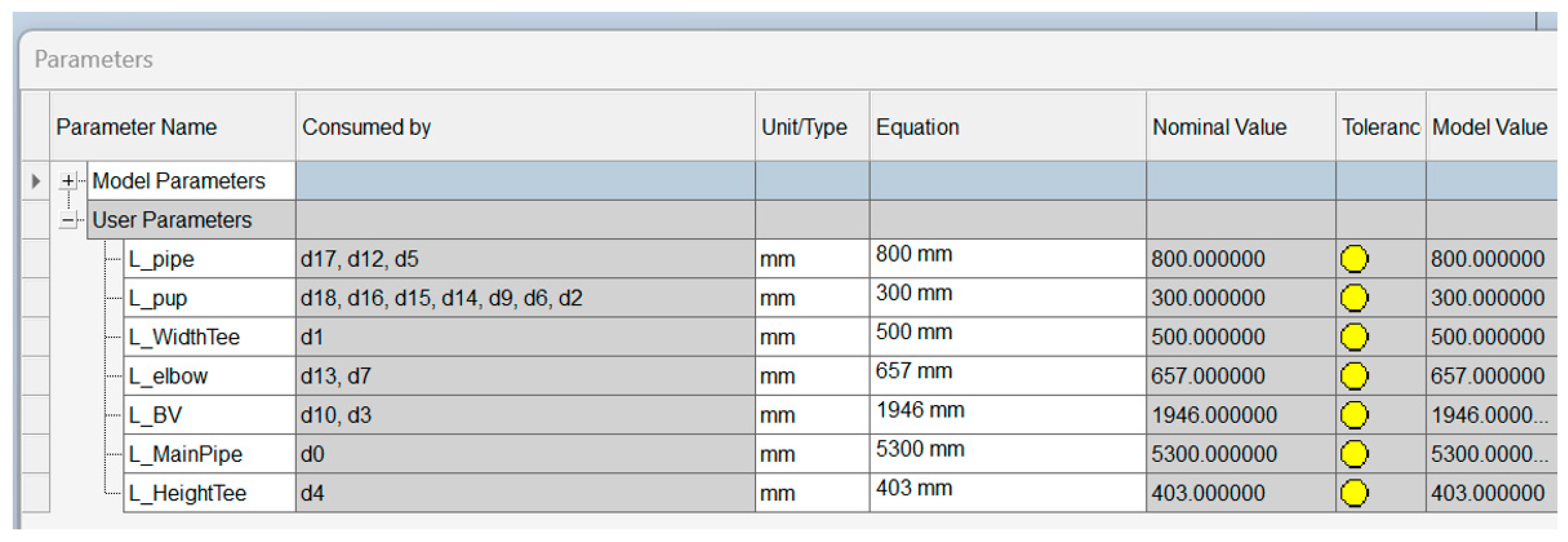
All assembly dimensions are governed by a centralised Autodesk Inventor Parameters table (Manage → Parameters), populated via the iLogic ILT_Parametric_Main rule module. Table 1 presents the seven user parameters extracted directly from the Inventor model. The Inventor Parameters table interface is shown in Figure 4 (see Results) for reference alongside the 3D model outputs.
2.3. ILT Configurations Modelled
Two ILT configurations were modelled within the same parametric assembly framework, as shown conceptually in Figure 1 and realised as 3D assemblies in Figure 2 and Figure 3:
- ILT Type 1 (Single Branch): A single lateral branch rises from the tee junction, connecting via pup pieces and an elbow to one ball valve (BV) sub-assembly and one outlet connection horizontal and vertical termination. The left-side BV is absent. The completed 3D model is shown in Figure 2.
- ILT Type 2 (Dual Branch with Full BV Assemblies): The assembly is extended to include a second ball valve sub-assembly on the left lateral of the main pipeline, and a second branch with elbow and pup connections on the right, terminating at a horizontal and vertical outlet, as shown in Figure 3. This configuration represents a more complex ILT deployment typical of multi-well tie-in systems.
2.4. Modelling Procedure
The ILT assembly was constructed in Autodesk Inventor Professional 2024 using the following sequential procedure: (1) a new metric Standard (mm).iam assembly file was created; (2) the pipe cross-section (OD = 273.1 mm, WT = 12.7 mm) was defined as shared sketch geometry referenced by all pipe components; (3) the parameter table in Table 1 was populated using the ILT_Parametric_Main iLogic rule; (4) individual components (main pipe, tee, pup pieces, elbows, BV assemblies) were modelled as separate .ipt part files with dimensions referencing the master parameters via adaptive constraints; (5) all components were assembled using coincident and mate constraints; (6) parametric update testing and interference analysis were performed as described in Section 2.5.
2.5. Validation Protocol
Validation was conducted through three stages: (i) parametric update testing — each parameter in Table 1 was individually modified and the assembly was regenerated, with all dependent features inspected for update correctness; (ii) interference analysis — Inspect → Interference Analysis was applied to the full assembly to verify zero geometric overlap between components; (iii) drawing view verification — projected views and dimension annotations were confirmed to update automatically upon parameter revision.
3. Results
3.1. Parametric Assembly Models (3D)
The completed parametric ILT assembly models for Type 1 and Type 2 configurations are shown in Figure 2 and Figure 3 respectively. All dimension labels visible in the figures correspond directly to the parameter names in Table 1, confirming that the assembly geometry is fully driven by the centralised parameter table.
3.2. Parametric Validation Results
Table 2 summarises the parametric update validation and engineering compliance results for the ILT assembly.
The D/t ratio of 21.5 for the API 5L 273.1 mm × 12.7 mm pipe is well within the ASME B31.3 structural limit of 100, indicating a robust wall section with substantial pressure containment margin. For reference, the minimum D/t ratio for Schedule Standard 10¾ in NPS pipe is generally in the range of 18–22 depending on grade, and the value of 21.5 is consistent with the expected Schedule Std wall selection for subsea service.
3.3. Parametric Model Interface
Figure 4 shows the Autodesk Inventor Parameters table interface as it appears during the modelling session, confirming the seven user-defined variables and their nominal values as listed in Table 1. The yellow tolerance indicator icons confirm that all parameters are within their defined nominal ranges and are active in driving the assembly geometry.
Figure 4.
Autodesk Inventor Parameters table showing the seven user-defined variables governing the ILT assembly geometry, with nominal values conforming to API 5L 273.1 mm OD × 12.7 mm WT pipe schedule.
Figure 4.
Autodesk Inventor Parameters table showing the seven user-defined variables governing the ILT assembly geometry, with nominal values conforming to API 5L 273.1 mm OD × 12.7 mm WT pipe schedule.
4. Discussion
The parametric modelling framework demonstrated in this study delivers measurable engineering value across three dimensions. First, the centralised parameter table reduces variant generation from a multi-hour rebuild to a parameter update taking seconds — a direct productivity benefit for design projects requiring multiple NPS sizes or assembly configurations. Second, the unified Type 1 / Type 2 model eliminates the dimensional synchronisation overhead inherent in maintaining separate model files per configuration. Third, the embedded D/t and wall thickness compliance checks provide immediate design governance feedback, preventing out-of-compliance configurations from propagating into downstream documentation.
From a standards perspective, the API 5L 273.1 mm OD × 12.7 mm WT pipe selection is appropriate for subsea flowline service. Under DNV-ST-F101 [1] and ASME B31.4 [9] (for liquid hydrocarbon transport systems), subsea pipeline wall thickness selection must account for internal pressure containment, external collapse (for deepwater applications), and combined loading. The D/t ratio of 21.5 is considerably lower than the collapse-critical threshold (typically D/t > 30 for deepwater collapse concerns), indicating that pressure containment rather than collapse governs the wall thickness selection for this specification at shallow to moderate water depths. For deepwater applications, a formal collapse check per DNV-ST-F101 Section 5 should supplement the parametric model outputs.
The ball valve (BV) assembly — modelled as a discrete parametric component governed by L_BV = 1946 mm — is a key differentiator of this ILT model compared to simpler pipeline tee representations. Its inclusion as a fully parametric, position-controlled component within the assembly enables interference-free layout validation of the complete ILT sub-system envelope, which is critical for subsea installation and ROV access planning. Future work should extend the framework to include iLogic-driven assembly envelope checks and ROV access zone verification directly within the Inventor environment.
5. Conclusions
This paper presented a parametric 3D modelling framework for a subsea ILT pipe assembly, applied to API 5L 273.1 mm OD × 12.7 mm WT pipe in Autodesk Inventor Professional. The key findings are:
- (1)
- A seven-parameter centralised parameter table (L_MainPipe, L_pipe, L_pup, L_WidthTee, L_HeightTee, L_elbow, L_BV) governs all critical assembly dimensions and drives both ILT Type 1 (single BV) and Type 2 (dual BV) configurations from a unified model.
- (2)
- The API 5L 273.1 mm × 12.7 mm pipe specification yields a D/t ratio of 21.5, well within the ASME B31.3 structural limit of 100, confirming the wall thickness as adequate for subsea pressure containment at the baseline design condition.
- (3)
- All six validation checks returned PASS, including parametric update testing across all seven parameters, zero interference conflicts in both assembly configurations, automatic drawing annotation update, and successful Type 1 to Type 2 configuration switching.
- (4)
- The framework is aligned with DNV-ST-F101, ISO 13628-1, ASME B36.10M, ASME B31.4 [9], and API 5L requirements and is recommended as a standard methodology for ILT parametric assembly modelling in offshore pipeline design.
Author Contributions
Conceptualisation, M.S.B.H.; Methodology, M.S.B.H.; Software, M.S.B.H.; Validation, M.S.B.H.; Writing — Original Draft, M.S.B.H.; Writing — Review & Editing, M.S.B.H. The author has read and agreed to the published version of the manuscript.
Funding
This research received no external funding.
Data Availability
iLogic script files and Inventor assembly files are available from the corresponding author upon request.
Conflicts of Interest
The author declares no conflict of interest.
References
- DNV. DNV-ST-F101 Submarine Pipeline Systems; Det Norske Veritas: Oslo, Norway, 2021.
- ISO 13628-1:2005; Petroleum and Natural Gas Industries — Design and Operation of Subsea Production Systems — Part 1: General Requirements and Recommendations. ISO: Geneva, Switzerland, 2005.
- American Petroleum Institute. API 5L: Specification for Line Pipe, 46th ed.; API: Washington, DC, USA, 2018.
- American Society of Mechanical Engineers. ASME B36.10M-2015: Welded and Seamless Wrought Steel Pipe; ASME: New York, NY, USA, 2015.
- American Society of Mechanical Engineers. ASME B31.3-2020: Process Piping; ASME: New York, NY, USA, 2020.
- Lombard, M. Inventor 2014 and Inventor LT 2014 Essentials; John Wiley & Sons: Indianapolis, IN, USA, 2013.
- Autodesk Inc. Autodesk Inventor Professional 2024 — Help Documentation; Autodesk Knowledge Network: San Rafael, CA, USA, 2024.
- ISO 13628-4:2010; Petroleum and Natural Gas Industries — Design and Operation of Subsea Production Systems — Part 4: Subsea Wellhead and Tree Equipment. ISO: Geneva, Switzerland, 2010.
- American Society of Mechanical Engineers. ASME B31.4-2019: Pipeline Transportation Systems for Liquids and Slurries; ASME: New York, NY, USA, 2019.
- S. Manakkattil Sivaraman and J. Venkataramana Reddy, —Toward AI-Assisted Conceptual Design of Subsea Inline Structures: Classification and Strain Behaviour of Inline Components during S-Lay Installation , International Journal for Research in Applied Science & Engineering Technology (IJRASET), vol. 14, no. 7, pp. 1127–1176, Jul. 2026.
Figure 1.
ILT configuration concept sketches: Type 1 (left panel, single-branch with header valve arrangement on main line) and Type 2 (right panel, dual-branch with full header valve arrangement), illustrating the schematic pipeline and valve configurations modelled in this study.
Figure 1.
ILT configuration concept sketches: Type 1 (left panel, single-branch with header valve arrangement on main line) and Type 2 (right panel, dual-branch with full header valve arrangement), illustrating the schematic pipeline and valve configurations modelled in this study.
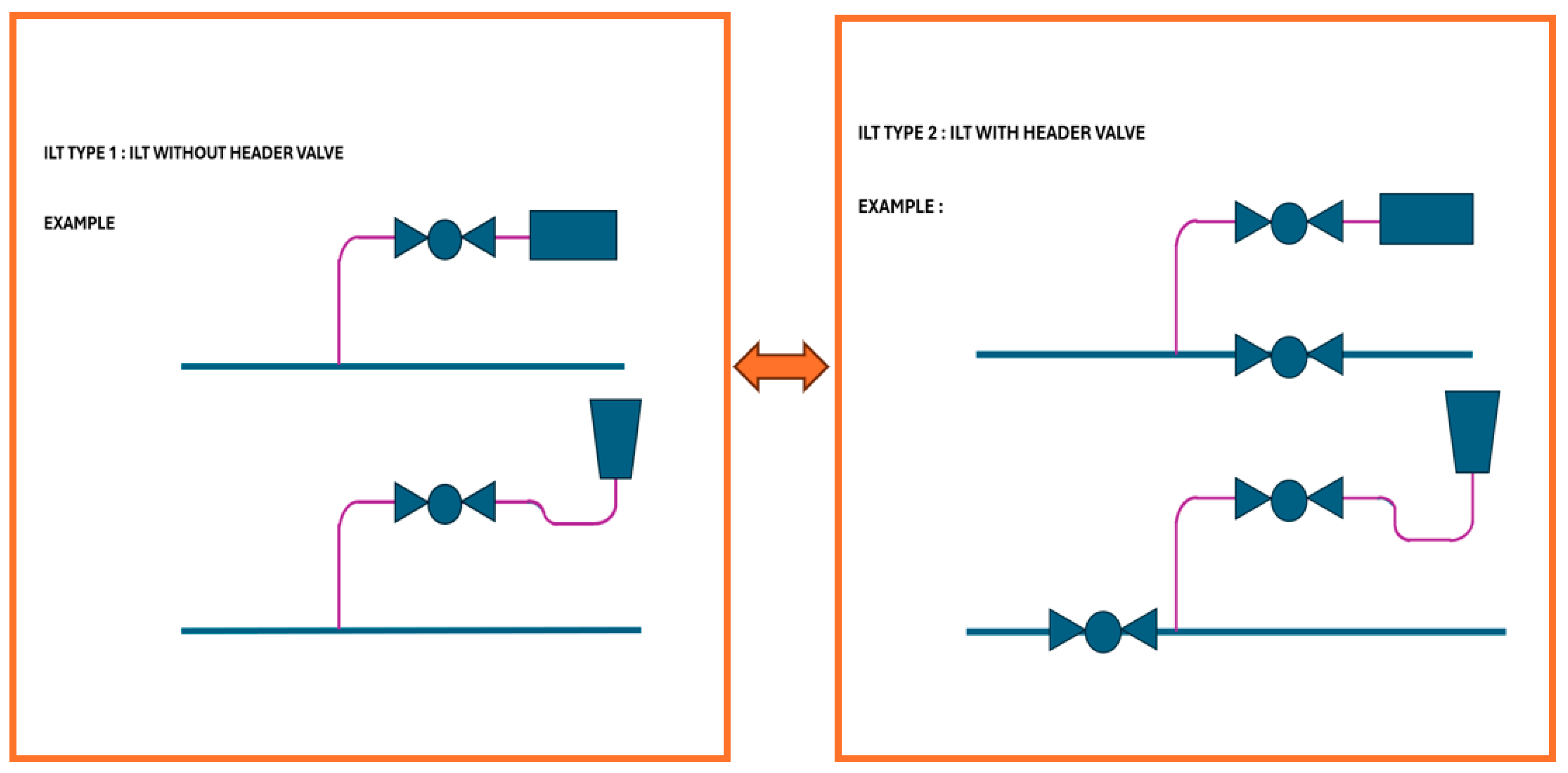
Figure 2.
ILT Type 1 parametric assembly — single lateral branch with one ball valve (BV) sub-assembly. All dimension labels correspond to parameters in Table 1. Pipe: API 5L 273.1 mm OD × 12.7 mm WT.
Figure 2.
ILT Type 1 parametric assembly — single lateral branch with one ball valve (BV) sub-assembly. All dimension labels correspond to parameters in Table 1. Pipe: API 5L 273.1 mm OD × 12.7 mm WT.
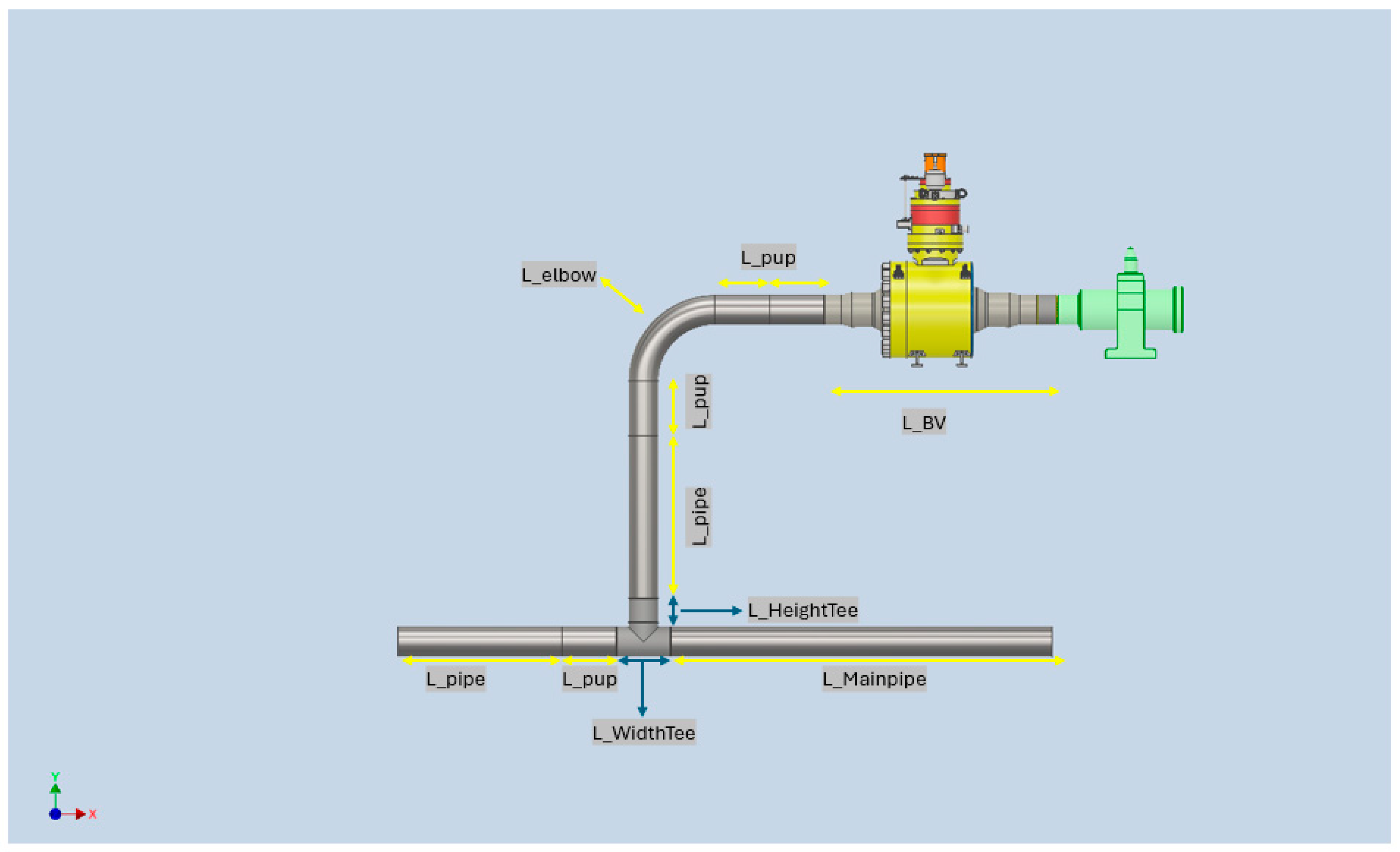
Figure 3.
ILT Type 2 parametric assembly — dual-branch configuration with full ball valve (BV) sub-assemblies on both laterals. All dimension labels are parametrically driven. Pipe: API 5L 273.1 mm OD × 12.7 mm WT.
Figure 3.
ILT Type 2 parametric assembly — dual-branch configuration with full ball valve (BV) sub-assemblies on both laterals. All dimension labels are parametrically driven. Pipe: API 5L 273.1 mm OD × 12.7 mm WT.
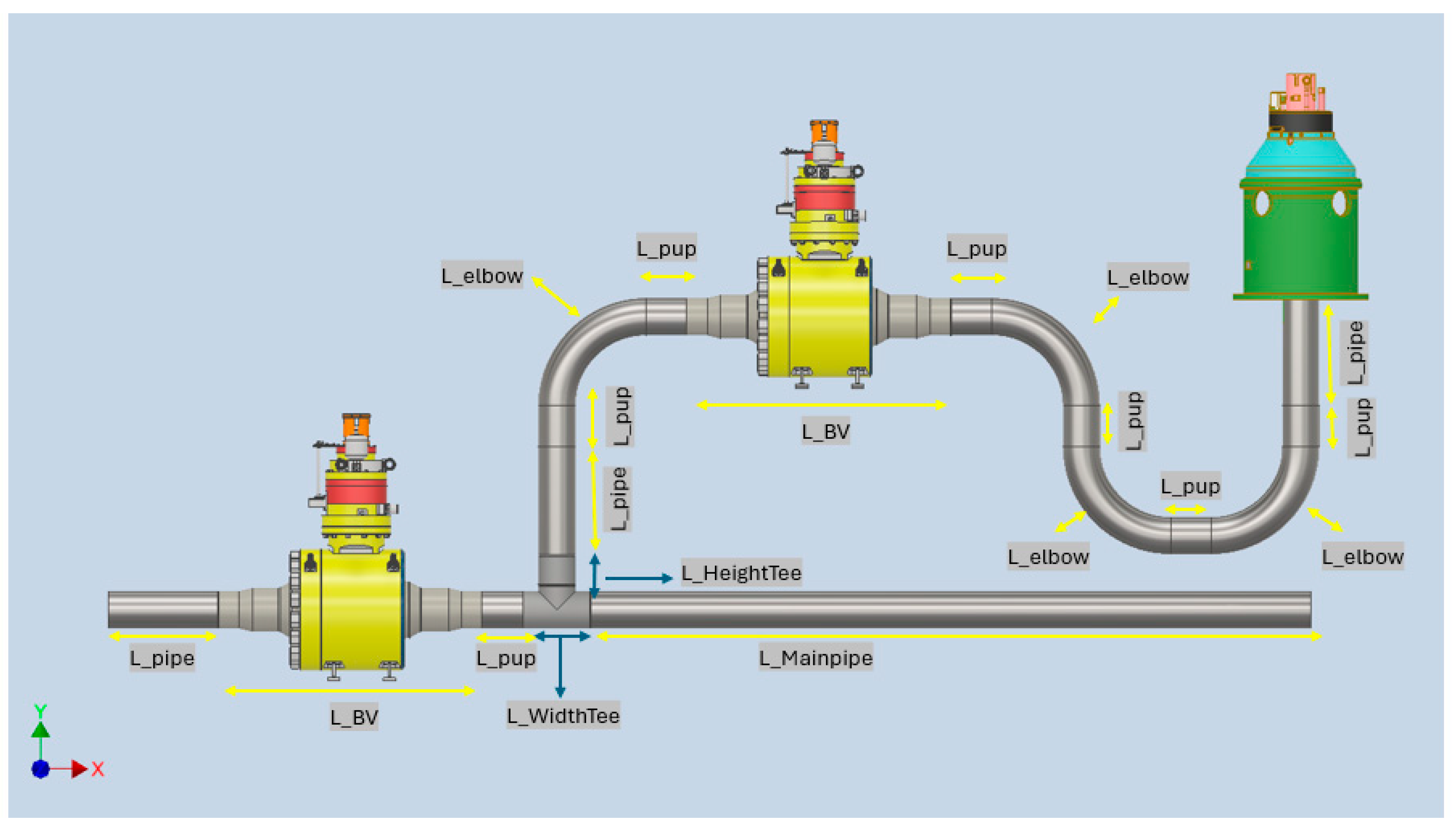

Table 1.
Centralised parameter table for the ILT parametric assembly (API 5L 273.1 mm OD × 12.7 mm WT).
Table 1.
Centralised parameter table for the ILT parametric assembly (API 5L 273.1 mm OD × 12.7 mm WT).
| Parameter | Value | Unit | Description |
| L_MainPipe | 5300 | mm | Total length of the main carrier pipeline |
| L_pipe | 800 | mm | Lateral pipe section length on each branch |
| L_pup | 300 | mm | Short pup piece length connecting tee to elbow/BV |
| L_WidthTee | 500 | mm | Tee junction width (transverse branch dimension standard size) |
| L_HeightTee | 403 | mm | Tee junction height (vertical branch offset standard size) |
| L_elbow | 657 | mm | Elbow fitting length (arc centre-to-end dimension standard size) |
| L_BV | 1946 | mm | Ball valve assembly total length (including flanges) |
Table 2.
Parametric validation and engineering compliance results.
| Check | Value / Criterion | Finding | Result |
| Parametric update — all 7 params | Modified & regenerated | All dependent features updated; zero failures | PASS |
| D/t ratio check (ASME B31.3) | 21.5 ≤ limit 100 | Substantial margin; wall thickness adequate | PASS |
| Min wall thickness check | 12.7 mm ≥ 3 mm min | WT meets minimum structural criterion | PASS |
| Interference analysis (full assembly) | 0 conflicts | No geometric overlap in Type 1 or Type 2 | PASS |
| Drawing view update | All views auto-updated | Annotations reflected parameter changes | PASS |
| Type 1 → Type 2 config switch | BV group activation | Dual-BV assembly activated without failure | PASS |
Disclaimer/Publisher’s Note: The statements, opinions and data contained in all publications are solely those of the individual author(s) and contributor(s) and not of MDPI and/or the editor(s). MDPI and/or the editor(s) disclaim responsibility for any injury to people or property resulting from any ideas, methods, instructions or products referred to in the content. |
© 2026 by the authors. Licensee MDPI, Basel, Switzerland. This article is an open access article distributed under the terms and conditions of the Creative Commons Attribution (CC BY) license (http://creativecommons.org/licenses/by/4.0/).
Copyright: This open access article is published under a Creative Commons CC BY 4.0 license, which permit the free download, distribution, and reuse, provided that the author and preprint are cited in any reuse.