
Submitted:
23 June 2026
Posted:
24 June 2026
You are already at the latest version
Abstract
The main objective of this study is to obtain the average parameters of gas-discharge plasma when controlling the steady position of the bow shock wave (BSW) using the combined action of a gas discharge initiated by a current from an external source and a magnetic field near the frontal surface of the model. The studies were carried out using both experimental and numerical methods in xenon and air. A comparison of the numerical and experimental dependences of the relative distance of the steady BSW from the model on the discharge power showed good agreement. Based on the conducted flow modeling, taking into account the dependence of the adiabatic index on the degree of ionization and the degree of nonequilibrium, and using the Burm's theory, gas-discharge plasma characteristics were obtained, such as the degree of ionization and the degree of nonequilibrium, the electron density and the electron temperature in the absence and presence of a magnetic field. By this way an integrated experimental-computational system was formed in which the measured characteristics of the discharge and BSW, as well as the numerically obtained averaged plasma parameters in the impact zone, are combined with the Burm's theory to clarify the thermodynamic state of the medium and determine the corresponding characteristics of the gas-discharge plasma. The obtained results can be used to develop control systems for high-speed flows that take into account the influence of plasma parameters and the electric and magnetic fields.
Keywords:
high-speed flow
; gas discharge
; near-surface energy deposition
; plasma
; magnetohydrodynamic method
; Lorentz force
; bow shock wave control
1. Introduction
Low-temperature plasma magnetohydrodynamics has been developing since the late 1950s, initially in close connection with the direct conversion of high-speed conducting-flow energy. The classical foundations of MHD interaction in weakly ionized gases and plasmas are presented in the monographs [1,2], while conducting low-temperature plasma flows in channels and magnetic fields are discussed in detail in [3,4]. The governing physical mechanism is the Lorentz force acting on charged particles. When an ionized medium moves across a magnetic field, charge separation produces a magnetically induced electromotive force, and a closed external circuit with wall electrodes generates an electric current. In the early stage, this mechanism was mainly considered for MHD generators and expansion channels, where the incoming flow was usually treated as continuous and free of pronounced dissipative structures.
The development of rocket technology and supersonic aviation shifted attention from energy-conversion applications toward active control of high-speed flows. Behind a BSW, high temperatures can produce natural ionization, so the closure of an induced ring current in this region provides a way to exert an electromagnetic force on the flow. Early experiments and studies of blunt-body flows showed that a magnetic field can change the bow-shock position and increase the bow-shock stand-off distance relative to the undisturbed case [5,6,7]. A further group of studies examined MHD control of shock-wave structures in air intakes and external supersonic flows. In work on hypersonic inlet configurations, different flight altitudes and regimes, magnetic-field geometries, and methods for increasing air conductivity were considered, including electron-beam ionization [8]. These formulations established the basis for computational and experimental analysis of acceleration, deceleration, and restructuring of weakly ionized supersonic flows.
Advances in numerical methods made it possible to model MHD interaction in shock-containing high-speed flows. Simulations with low magnetic Reynolds numbers showed that an applied magnetic field can reduce the heat flux near the stagnation point of a blunt body [9]. This result became one of the foundations of MHD thermal protection: the magnetic field displaces the hot ionized layer away from the surface and thereby lowers the thermal load. The same idea was later developed for reentry vehicles [10,11,12] and for the MHD parachute concept [13,14,15], in which a frontal magnetic field is intended to increase aerodynamic drag while reducing heat transfer.
The experimental basis of MHD aerodynamics includes plasma-flow studies and direct force measurements. Experiments with argon plasma recorded changes in thermal loading under magnetic-field action [16], while measurements in an expansion channel confirmed that an increase in aerodynamic drag can be registered during MHD interaction. These results are important because they connect the computational picture of Lorentz-force action and induced currents with measurable flow characteristics.
Current research treats MHD interaction as a tool for controlling flow structure, heat transfer, and aerodynamic braking in real high-temperature gases. Theoretical and numerical studies analyze bow-shock displacement and plasma characteristics during Mars-entry conditions [17,18], and review papers summarize plasma and MHD-control applications in high-speed aerodynamics [19]. Within the MEESST project, simulations using different chemical models reproduced experimental data and confirmed the expected MHD effects [11,12]. Experiments on MHD aerobraking under atmospheric-entry conditions showed an increase in bow-shock stand-off distance and a reduction in heat flux, supporting the practical potential of this approach [20].
The presented work continues this line of research for supersonic flows with shock-wave structures and localized electric and magnetic forcing. These studies show that a near-surface plasma region can influence the formation and location of the steady BSW in air and xenon, and that the plasma parameters determine both the formation rate and the final shock position [21,22,23]. Studies of internal and external flows also demonstrate that shock-wave positions and aerodynamic characteristics can be controlled by plasma, electric, and magnetohydrodynamic actions [24,25]. A distinctive feature of these studies is the use of not only an external magnetic field but also an electric field from an external source for MHD action to generate a gas-discharge current in localized flow regions during the flow, which allows for a wider range of intensities and directions of action.
In the presented work, based on experimental data and conducted modeling, an integrated experimental-computational system was created in which the measured characteristics of the discharge and BSW, as well as the numerically obtained averaged plasma parameters in the impact zone, were combined with Burma's plasma theory [26] to determine the averaged characteristics of gas-discharge plasma in cases of the absence of a magnetic field and for different directions of the MHD action. The numerical part of this research relies on computational-fluid-dynamics methods, specialized software for calculation of high-speed flows, and conservative difference schemes [27,28,29].
2. Experiment Arrangement and Results
To effectively control supersonic flows containing shock waves using magnetohydrodynamics, it is necessary to create a force action under the neutral gas in a selected, most convenient local region of the flow and in the desired direction. This is achieved by artificially generating the motion of charged particles in external electric and magnetic fields. Specifically, a gas discharge of the desired intensity is created in the selected impact zone, with a current in a given direction and a magnetic field perpendicular to the current. In this case, the charges moving in the magnetic field will be acted upon by the Lorentz force in a direction perpendicular to both the gas-discharge current I and the magnetic induction vector B.
When energy is transferred during collisions from heavy positive ions to neutral gas particles, a ponderomotive force arises equal in magnitude to the Ampere force FA acting on a current-carrying conductor, FA = I (B × L), where B is the magnetic induction vector, and L is the propagation vector, having the direction of the current and the length of the gas-discharge zone. This force will be directed perpendicular to both the magnetic induction vector and the current. Accordingly, a force of FL = FA/(S∙L) = J × B, conventionally called the Lorentz force, will act on a unit volume of gas in the affected zone, where S is the cross-sectional area of the gas discharge zone, and J is the vector having the direction of the gas discharge current and the magnitude of its density. If the magnetic field is directed perpendicular to the current, the magnitude of the Lorentz force will be equal to the product of the current density and the magnetic induction, FL = J∙B.
Thus, the method of active MHD control of supersonic flows involves creating locale plasma gas-discharge regions in an external magnetic field using an external current source. The location of the affected zones, discharge parameters, and the magnitude of the magnetic induction are determined based on the specific task. The main requirements for this method include the maximum possible magnetic induction and sufficient conductivity of the medium to increase the gas-discharge current density J and reduce the electric field strength in the discharge zone E in order to increase the Lorentz force and reduce Joule heating of the gas. Depending on the current from the external source, it is possible to create a Lorentz force directed either towards the streamlined model (Case FL+ or FL+ force) or away from it (Case FL- or FL- force). The specific objective of this study is to implement magnetohydrodynamic control of the BSW position in supersonic flow past a blunt semi-cylindrical model.
The experiment was conducted in a supersonic flat nozzle with a 22° opening angle. Figure 1a shows a diagram of the nozzle with the model positioned on its axis. During supersonic flow around the model, a BSW is formed in front of it. To impact BSW position a gas discharge zone is created near the leading edge of the cylinder by applying an external voltage Upl to electrodes embedded in the surface of the model and turning on a magnetic field with a magnetic induction vector B directed perpendicular to the gas discharge current I. The current propagates near the front surface of the model between the BSW and the body along a semicircular trajectory in a direction perpendicular to the magnetic field. In this case, a Lorentz force is exerted on the gas near the front edge of the model in the gas discharge zone. The direction of this force depends on the direction of the gas discharge current, and the intensity of this force depends on the magnitude of the gas discharge current. The intensity of the gas discharge changes depending on the change in the applied voltage Upl value. Figure 1b shows a schlieren picture of the supersonic flow around the model, visualizing the position of the stationary bow shock wave in the absence of a magnetic field.
If the gas-discharge current is directed from the upper electrode to the lower one, the Lorentz force FL+ will act toward the model, pressing the gas against its surface. This action is shown schematically in Figure 2a. In this case, the stationary position of the BSW changes; its location will be further from the body compared to Figure 1b, as evident from the schlieren pattern in Figure 2b, obtained with the magnetic field turned on. The graph of the distance d between the BSW and the model surface on the nozzle axis versus the magnitude of the Lorentz force in Figure 2c shows that as the force intensifies, the BSW moves further away from the body.
When the current direction changes from the lower to the upper electrode, the FL- force repels the gas from the model surface (see Figure 3a), and the position of the established BSW also changes, it approaches the model, as can be seen from a comparison of Figure 1b and Figure 2b and Figure 3b, which show the position of the BSW at the same currents, but with different directions of the Lorentz force. However, the magnetohydrodynamic effect in the case of FL- will occur against the background of the plasma effect, described in detail in [21,22], therefore it will have a narrower range of currents and voltages for reducing the distance between the BSW and the model, since the mechanism and degree of plasma action are determined by the amount of power supplied to the discharge zone and the change in plasma characteristics in the impact zone, which prevents the wave from approaching. The range of the impact force capable of prevailing over the plasma effect and bringing the BSW closer to the body will depend on the specific task. In this experiment, to decrease BSW stand-off distance the FL- must be in the range of 4-6.5 N/cm3, which can be seen from the graph in Figure 3c.
3. Numerical Simulations
3.1. Methodology and Statement of the Problem
In the experiment, an electric current from an external energy source is generated, producing a gas discharge and at the same time an external magnetic field is organized acting in the gas-discharge plasma region. The flow from the shock tube, upon reaching the body, initiates the formation of a bow shock wave (BSW), which passes through the gas-discharge plasma zone affected by the plasma parameters and the impact of the MHD interactions. The calculations assume that this impact zone arises instantaneously due to the difference in the time scales of gas-discharge plasma formation, the occurrence of the ponderomotive force (Lorentz force) acting on charged particles, and gas-dynamic phenomena.
Thus, the effect of the discharge and the external magnetic field is modeled by the action of a volumetric gas region with increased energy and a modified adiabatic index and impact of the Lorentz force. Figure 4 shows a schematic of a numerical approach to studying the influence of near-surface plasma energy combined with MHD impact, on a supersonic flow around a "semi-cylindrical plate"- shaped body. The zone of influence of the discharge and magnetic field is marked in red.
The simulations are based on the Navier–Stokes equations for perfect viscous heat-conducting gas: xenon and air are considered. The full Navier–Stokes system of equations in the divergence form for the dimensionless variables [27] added by the right parts associated with plasma and MHD actions is solved numerically:
The specific power in the area of higher gas energy formed by the discharge is q, and the specific internal energy is ε.
For the dependence of dynamic viscosity μ on temperature T for air, Sutherland's law was used,
where s1=0.084. For xenon it was assumed that
The coefficient of heat conductivity k is modeled to depend on temperature in the same way:
When the Lorentz force is directed towards the body (Case +) the right parts in the equations for the impulse components are:
And when the Lorentz force is directed from the body (Case -) the right parts in the equations for the impulse components are:
Here is the acute angle between Lorentz force direction and x-axis; the absolute value of the Lorentz force produced by the external magnetic field is:
where J is the current density.
Additional term in the right side of the energy equation in (1) is connected with the specific power of the discharge-created plasma q0 and the work of the Lorentz force. So, the specific power q (the power per unit of mass) is expressed as follows:
Here the work of the Lorentz force is supposed to be proportional to |FL|kmhd is the variable coefficient (dimensional).
The problem is solved in dimensionless variables; the following normalizing coefficients were used in the calculations:
where: the index ∞ defines the freestream parameters. In the following figures, where not specifically stated, the values on the axes are taken in dimensionless form.
Initial conditions are the freestream flow parameters: density , pressure , and velocity According to the evaluation of the experimental data [22], we suppose that in xenon the adiabatic index in the oncoming flow is γ = 1.217, and the adiabatic index in the plasma area in front of the body is γs= 1.258. Therefore, for xenon the problem is solved taking into account the initial gas ionization. For air the initial ionization is small, and it is not taken into account [21]; the adiabatic index in the oncoming flow is γ = 1.323. At the boundaries of the body, the boundary conditions of solid adiabatic wall with no-slip conditions are used; non-reflecting boundary conditions in the normal direction to the wall are used at the exit boundaries.
The stationary domain with higher gas energy models the near-surface energy release with the use of the right-hand sides of the impulse and energy equations in (1), where |FL| is defined by (2), and q is the specific power (3) in this region (this area is noted by red in Figure 4). The width of this area in the x-direction is assumed to equal to 0.1D, which is in accordance with the experimental schlieren images. This region is assumed to arise instantaneously and is determined by the initial conditions and the values of q and FL. The mechanism of action of the impact region is associated with the fact that the BSW passes through the already existing region of the impact during its formation at the non-steady stage, thus, its characteristics at the steady state are influenced by the parameters in this region [21].
The simulation is performed using a domestic computational code [28] based on complex-conservative difference schemes [29]. The schemes have the second order of accuracy in space and time. The stencil of the well-known Lax scheme is used; therefore, a shifted uniform grid is used throughout the computational domain. To increase the order of approximation, differential consequences of system (1) for partial derivatives with respect to x and y are used. Thus, in addition to the main conservative variables, their first derivatives are used as conservative variables. These derivatives are considered as unknown functions and are calculated on the same stencil. The required second derivatives are calculated using the values of the first derivatives at the grid nodes. The surfaces of the AD body are embedded in the computational domain without violating the conservation laws, including the regions adjacent to the body surfaces. This is achieved through the use of fractional cells in these regions. The position of the front surface of the body on the computational grid is shown in Figure 5.
Details of the construction of these schemes within the computational domain and near the boundaries of the AD body are presented in [29]. It should be noted that a number of test cases related to the numerical methods used, comparison with experimental results, as well as test cases for grid convergence analysis for the developed software are also presented in [29].
3.2. Numerical Study of flow Parameters Under the Influence of Plasma and a Magnetic Field
The parameters of gas discharge and magnetic field for which the simulations were carried out for xenon and the parameters obtained in the calculations are presented in Table 1. The determining flow parameters and normalizing coefficients adopted in modeling the effect of a near-surface discharge in xenon and in air are given in Table 2 and Table 3.
For air, experimental data are available only for the action of the plasma region (in the absence of MHD influence), therefore the MHD effect was modeled assuming that kmhd= 1 for the Case Fx+, and kmhd = -1 for the Case Fx-.
In Figure 6, the numerical fields of density and temperature are shown at the steady-state flow mode, at time t=2.0 for different q0, γs, for the Cases Fx+ and Fx-. It is evident that in the zone of influence of the discharge and external magnetic field, the gas density decreases and temperature increases in the case Fx+, and BSW moves from the body (upper images); and density increases and temperature decreases in the case Fx-, and BSW moves towards the body (bottom images). This confirms the experimental results and gives the instrument for control the BSW position (along with the characteristics of AD body).
Figure 6.
Fields of density (a) and temperature (b) in xenon under the action of the Lorentz force for the FL+ (upper) and FL- (bottom), q0 = 119.5, γs=1.275, FL+=52.16, |FL-|=46.2.
Figure 6.
Fields of density (a) and temperature (b) in xenon under the action of the Lorentz force for the FL+ (upper) and FL- (bottom), q0 = 119.5, γs=1.275, FL+=52.16, |FL-|=46.2.
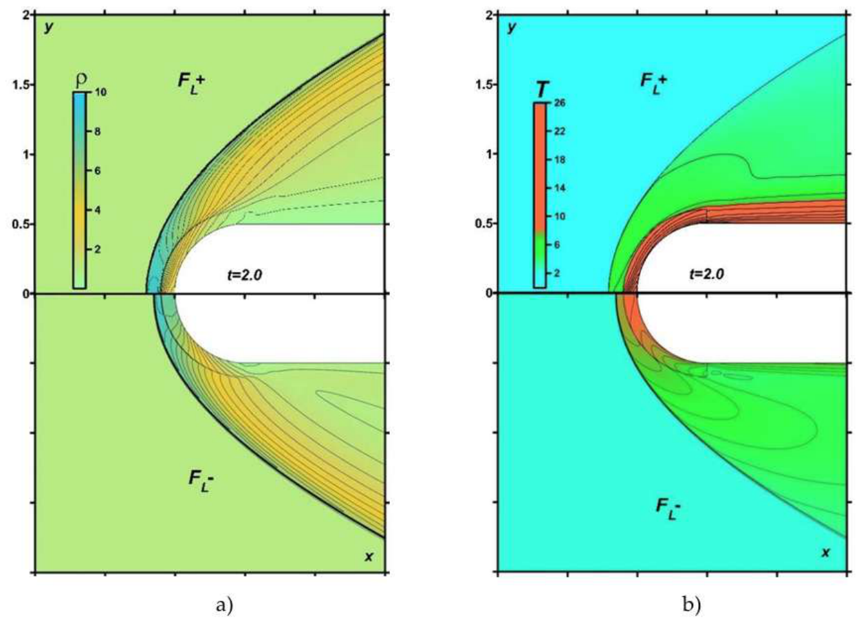
Figure 7.
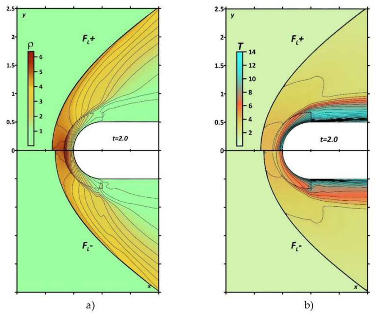
Fields of density (a) and temperature (b) in air under the action of the Lorentz force, q0 = 101, γs=1.24: FL+=10 and kmhd = 1 (upper) and FL-|=10 and kmhd = -1 (bottom).
Figure 7.
Fields of density (a) and temperature (b) in air under the action of the Lorentz force, q0 = 101, γs=1.24: FL+=10 and kmhd = 1 (upper) and FL-|=10 and kmhd = -1 (bottom).
Based on the obtained values of density and temperature in the gas discharge plasma zone, their average values in this area were calculated. The averaged characteristics were calculated, as follows:
where fa is the averaged value, f(i,j) is the value of f in the grid node (i,j), and N is the amount of nodes included in the plasma area. Only the values f(i,j) contained in the impact region are taken to account.
Figure 8a and Figure 8b present the calculated and experimental values of the relative stand-off distance of the steady BSW from the model in xenon and air, accordingly, for different values and different directions of the Lorentz force FL; average temperature values in the plasma region are also shown. In air, the calculated and experimental values are compared only for the action of the plasma zone, without the MHD action.
3.3. Evaluation of the Gas-Discharge Plasma Parameters in Xenon and Air
As noted earlier, the MHD effect at the model surface during the creation of gas-discharge zones from an external source occurs against the background of plasma action [21,22], which significantly influences the flow process even in the absence of a magnetic field. The energy input into locally created gas-discharge zones in the near-surface region of the model leads to changes in the plasma characteristics in these zones, which affects gas-dynamic processes. Figure 9 shows the dependencies of the power input into the discharge region (Figure 9a) and the changing electron concentration (Figure 9b) on the gas-discharge current for two working gases: monatomic xenon and diatomic air (N2). It is evident that to achieve plasma conditions in air similar to those in xenon and sufficient to noticeably influence the position of the BSW, the input energy must be at least 4 times greater than the energy input into xenon.
Since the adiabatic index of the medium, which determines gas-dynamic processes in the plasma zone, depends on the degree of ionization and the degree of nonequilibrium [26], it will vary significantly in the affected zone, as can be seen from Figure 10. Figure 10a shows the dependencies of the adiabatic index on the degree of nonequilibrium, calculated according to Burm's theory [26] using the experimental values of the electron concentration and the calculated values of the averaged gas density and temperature in the impact zone for air. The figure demonstrates the range of possible values of the adiabatic index under the experimental conditions. The same calculations were made for xenon (Figure 10).
The dependencies of the values obtained in the numerical simulation on the current for two gases are shown in Figure 10c. A comparison of these data showed that in xenon the adiabatic index calculated according to Burm's theory practically coincides with the value in the model experiment under the condition of thermal equilibrium, when θ=1 (see, also, [22]). In air, the model values coincide at θ=0.3, while at θ=1, the values are significantly lower. This can be explained by the presence of dissociation of diatomic molecules under the heating conditions in the experiment, which was not taken into account in the model used for air, as well as by the possible nonequilibrium state of the air in the impact zone. Accounting for these factors is the task of future numerical studies. Figure 10c shows the adiabatic indices, both from the model experiment and calculated using Burm's theory at θ=1. Table 4 and Table 5 summarize the main gas parameters in the impact zone at the leading edge of the model for different gas discharge intensities.
3.4. Evaluation of the Gas-Discharge Parameters Under the MHD Action of Different Directions in Xenon
To diagnose the state of the impact zone in xenon at different values of external fields, the volt-ampere characteristics of the discharge were measured in the experiment, namely, the magnitude of the gas-discharge current and the corresponding value of the voltage on the plasma gap were measured. Based on the obtained data, the power supplied to the circuit and the electron concentration in the gas-discharge zone were estimated. The dependences of these parameters on the current for two directions of MHD impact are shown in Figure 11. The range of the input energy is 0-100 kW, while the resulting electron concentrations of the gas-discharge plasma increase from 1.5·1022 to 3.5·1022 m-3. Using the calculated values of the averaged gas density and temperature, the degree of ionization was determined and the values of the adiabatic index were found, the value of which, according to Burm's theory [26], is determined by the plasma characteristics of the medium, namely the degree of ionization α and the degree of nonequilibrium θ=Ta/Te.
Figure 12 shows the dependences of the adiabatic index on the degree of nonequilibrium for the obtained degrees of ionization and gas temperature for the FL+ case. The main parameters of the affected zone and the refined values of the adiabatic index are presented in Table 6. Since the medium in the affected zone can be considered to be in equilibrium during abrupt flow deceleration in front of the body, the refined data were taken at θ = 1. Similar data for the FL- case are shown in Figure 13 and Table 7.
The dependences of the degree of ionization, electron temperature, and adiabatic index on the magnitude of the gas-discharge current for two cases of the Lorentz force direction, shown in Figure 14, demonstrate that different directions of MHD action change the parameters of the affected zone differently. With an increase in the gas discharge intensity at low currents, the MHD effect is weak, and the parameters are similar for different directions. A turning point occurs at a current of 450 A, and the dependences change dramatically. At FL+, all parameters increase sharply, while at FL-, the temperature and adiabatic index decrease, with γ falling below the initial value obtained in the absence of external fields. At higher currents, the parameters tend to converge. It should be noted that the MHD effect in the case of FL-, for decreasing the distance between the BSW and the model, operates in the current range of 450–800 A. This current range corresponds to a sharp difference in the plasma zone parameters.
4. Conclusions
In this study, experimental and numerical methods were used to investigate the influence of the MHD impact combined with an artificially generated gas-discharge current from an external source near the front surface of the body for controlling supersonic flow including the position and shape of the bow shock wave. In the experiment, with two current closure directions and MHD action, and for purely plasma action (without MHD impact) plasma characteristics in the discharge zone were measured, such as the energy deposited in the discharge, the electron concentration, and the degree of ionization. The range of currents within which active control of the bow shock wave position is possible was determined as 450-800 A.
Based on the Burm's theory and calculated gas parameters, the electron temperature and the adiabatic index of the medium in the impact zone were determined for two directions of the Lorentz force action and for the case of absence of MHD action. It was shown that the direction of the force impact influences the change in these characteristics with current within the active control range. It was obtained that when the Lorentz force is directed towards the model, these parameters increase; when the Lorentz force is directed from the body, they decrease.
By this way, an integrated experimental-computational system was formed in which the measured characteristics of the discharge and bow shock wave, as well as the numerically obtained averaged plasma parameters in the impact zone, are combined with Burm's plasma theory to clarify the thermodynamic state of the medium and determine the corresponding characteristics of the gas-discharge plasma in cases of the absence of a magnetic field and for different directions of its action.
Thus, the study demonstrates the feasibility of active controlling the bow shock wave position both as to increase or to decrease stand-off distance using the locally organized external electrical and magnetic fields. Furthermore, the possibility of influencing the gas-discharge plasma parameters was assessed and demonstrated. The results presented may be of interest for the development of high-speed flow control systems based on plasma generation and the organization of MHD action with various directions.
Author Contributions
Data curation, methodology – Olga Azarova and Tatiana Lapushkina; investigation, visualization – Olga Azarova, Tatiana Lapushkina, and Ekaterina Reshetova; formal analysis and writing original draft – all authors; Software – Olga Azarova, Oleg Kravchenko; Validation – Olga Azarova; Supervision – Olga Azarova.
Funding
The study was supported by the Russian Science Foundation, project No. 25-21-00491.
Acknowledgments
The computations were carried out using the infrastructure of the Shared Research Facilities «High Performance Computing and Big Data» (CKP «Informatics») of FRC CSC RAS.
Conflicts of Interest
The authors declare no conflict of interest.
Nomenclature
| Abbreviations | |
| AD | aerodynamic |
| BSW | bow shock wave |
| MHD | magnetohydrodynamic |
| Parameters | |
| D, m; R, m | diameter and radius of an AD body |
| d, m | BSW SD from the body |
| I, A | gas discharge current |
| J, A/m3 | density of gas discharge current |
| M∞ | freestream Mach number |
| M1 | shock wave Mach number in the shock tube |
| ne, m−3 | electron concentration |
| p, P, ρ, kgm−3, T, K | pressure, density, and temperature of the gas |
| P, W | discharge power |
| q, kW/kg | specific power of a discharge |
| Re, Pr | Reynolds number and Prandtl number |
| Upl, V | voltage across the discharge gap |
| FL, N/m3 | Lorentz force (per unit of volume) |
| α | degree of ionization |
| γ | adiabatic index (ratio of specific heats, isentropic exponent) |
| γs | adiabatic index in the discharge-created plasma region |
| Ɵ | degree of nonequilibrium |
| Indices | |
| 0 | parameters at the absence of energy deposition |
| a | average flow parameters in the discharge-created plasma |
| n | normalizing parameters |
| ∞ | freestream parameters |
| e | parameters of electrons |
References
- Sutton, G. W.; Sherman, A. Engineering magnetohydrodynamics; McGraw-Hill: London, UK, 1965; 548 p.
- Pai, Shih-I. Magnetogasdynamics and plasma dynamics; Springer: Vienna, Austria, 1962; 197 p.
- Vulis, L. A.; Genkin, A. L.; Fomenko, B. A. Theory and calculation of magnetogasdynamic flows; Atomizdat: Moscow, Russia, 1971; 384 p.
- Vatazhin, A. B.; Lyubimov, G. A.; Regirer, S. A. Magnetohydrodynamic flows in channels; Nauka: Moscow, Russia, 1970.
- Bush, W. B. Magnetohydrodynamic-hypersonic flow past a blunt body. Journal of the Aerospace Sciences 1958, 25(11), 685-690. [CrossRef]
- Ziemer, R. W.; Bush, W. B. Magnetic field effects on bow shock stand-off distance. Physical Review Letters 1958, 1(2), 58-59. [CrossRef]
- Kranc, S. Experimental investigation of magnetoaerodynamic flow around blunt bodies; NASA CR-1393; National Aeronautics and Space Administration: Washington, DC, USA, 1969.
- Gurijanov, E. P.; Harsha, P. T. AJAX: New direction in hypersonic technology. AIAA Paper 96-4609, 1996. [CrossRef]
- Poggie, J.; Gaitonde, D. V. Magnetic control of flow past a blunt body: Numerical validation and exploration. Physics of Fluids 2002, 14, 1720-1731. [CrossRef]
- Otsu, H.; Matsuda, A.; Abe, T.; Konigorski, D. Numerical validation of the magnetic flow control for reentry vehicles. AIAA Paper 2006-3236, 2006. [CrossRef]
- Lani, A.; Sharma, V.; Giangaspero, V. F.; et al. A Magnetohydrodynamic enhanced entry system for space transportation: MEESST. Journal of Space Safety Engineering 2023, 10(1), 27-34. [CrossRef]
- Giacomelli, J.; Herdrich, G.; Sharma, V.; Giangaspero, V.; Donaldson, N.; Kim, M.; Munafo, A.; Lani, A. Numerical rebuilding of magnetic heat flux control experiments for re-entry vehicles by enhanced MHD simulation tools. In Proceedings of the 2nd International Conference on Flight Vehicles, Aerothermodynamics and Re-Entry Missions & Engineering (FAR), 2022.
- Fomichev, V. P.; Yadrenkin, M. A. Experimental investigation of the magnetohydrodynamic parachute effect in a hypersonic air flow. Technical Physics 2013, 58(1), 144-147. [CrossRef]
- Fomichev, V. P.; Korotaeva, T. A.; Yadrenkin, M. A. Development of methods of magneto-plasma aerodynamics at the Institute of Theoretical and Applied Mechanics of the Siberian Branch of the Russian Academy of Sciences. Journal of Applied Mechanics and Technical Physics 2020, 61(5), 727-739. [CrossRef]
- Knapp, A.; Ono, N.; Haag, D.; Fertig, M.; Herdrich, G.; Auweter-Kurtz, M. Investigation of magnetohydrodynamic effect on steady state Argon plasma flow. In Proceedings of the 6th European Symposium on Aerothermodynamics for Space Vehicles, 2009; Volume 659, p. 112.
- Smith, D. R.; Gildfind, D. E.; Mee, D. J.; James, C. M.; Allsop, B. V. Magnetohydrodynamic drag force measurements in an expansion tunnel using a stress wave force balance. Experiments in Fluids 2020, 61(8), 180. [CrossRef]
- Tabuchi, K.; Fujino, T. Numerical study of plasma characteristics under magnetohydrodynamic flow control in Mars entry. Journal of Spacecraft and Rockets 2024, 61(6), 1680-1692. [CrossRef]
- Li, Y.; Wang, Q.; Luo, K.; Li, J.; Zhao, W. Theoretical analysis on hypersonic MHD shock stand-off distance of blunt body. Chinese Journal of Theoretical and Applied Mechanics 2021, 53(9), 2493-2500. [CrossRef]
- Li, Y.; Wang, Y.; Pang, L.; Xiao, L.; Ding, Z.; Duan, P. Research progress of plasma/MHD flow control in inlet. Chinese Journal of Theoretical and Applied Mechanics 2019, 51(2), 311-321. [CrossRef]
- Lefevre, A.; Gildfind, D. E.; Gollan, R. J.; et al. Magnetohydrodynamic experiments of total heat flux mitigation for superorbital earth reentry. AIAA Journal 2022, 60(9), 5046-5059. [CrossRef]
- Azarova, O. A.; Lapushkina, T. A.; Shustrov, Yu. A. Near-surface gas discharge effect on a steady bow shock wave position in a supersonic flow past a cylindrically blunted body in the air. Physics of Fluids 2022, 34(6), 066117. [CrossRef]
- Azarova, O. A.; Lapushkina, T. A.; Kravchenko, O. V. Impact of a near-surface plasma region on the bow shock wave and aerodynamic characteristics of a high-speed model in xenon. Fluids 2024, 9(12), 277. [CrossRef]
- Lapushkina, T. A.; Azarova, O. A.; Reshetova, E. V.; Belov, K. I. Zhurnal Tekhnicheskoi Fiziki 2025, 95(12), 2413. [CrossRef]
- Lapushkina, T. A.; Erofeev, A. V. Supersonic flow control via plasma, electric and magnetic impacts. Aerospace Science and Technology 2017, 69, 313-320. [CrossRef]
- Lapushkina, T. Principles of magnetohydrodynamical control of internal and external supersonic flows. Energies 2022, 15(15), 5641. [CrossRef]
- Burm, K. T. A. L.; Goedheer, W. J.; Schram, D. C. The isentropic exponent in plasmas. Physics of Plasmas 1999, 6(6), 2622-2627. [CrossRef]
- Roache, P. J. Computational fluid dynamics; Hermosa Publishers: Albuquerque, NM, USA, 1976.
- Azarova, O. A. FlowView software package; Rospatent, Registration No. 2022667647, 22 September 2022.
- Azarova, O. A. Complex conservative difference schemes for computing supersonic flows past simple aerodynamic forms. Computational Mathematics and Mathematical Physics 2015, 55, 2025-2049. [CrossRef]
Figure 1.
a) Schematic diagram of the model's location in a supersonic nozzle; b) Schlieren picture of the BSW position in the absence of the magnetic field, I=673 A.
Figure 1.
a) Schematic diagram of the model's location in a supersonic nozzle; b) Schlieren picture of the BSW position in the absence of the magnetic field, I=673 A.
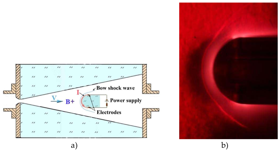
Figure 2.
a) Scheme of the Lorentz force FL+ action in the direction to the model; b) Schlieren picture of the position of the BSW under the MHD action to the model, I=655 A; c) Stand-off distance of the BSW under the action of FL+, B=1.4 T.
Figure 2.
a) Scheme of the Lorentz force FL+ action in the direction to the model; b) Schlieren picture of the position of the BSW under the MHD action to the model, I=655 A; c) Stand-off distance of the BSW under the action of FL+, B=1.4 T.
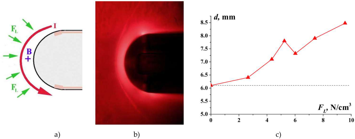
Figure 3.
a) Scheme of the Lorentz force FL- action in the direction from the model; b) Schlieren picture of the position of the BSW under the MHD action from the model, I=597 A; c) Stand-off distance of the BSW under the action of FL-, B=1.4 T.
Figure 3.
a) Scheme of the Lorentz force FL- action in the direction from the model; b) Schlieren picture of the position of the BSW under the MHD action from the model, I=597 A; c) Stand-off distance of the BSW under the action of FL-, B=1.4 T.
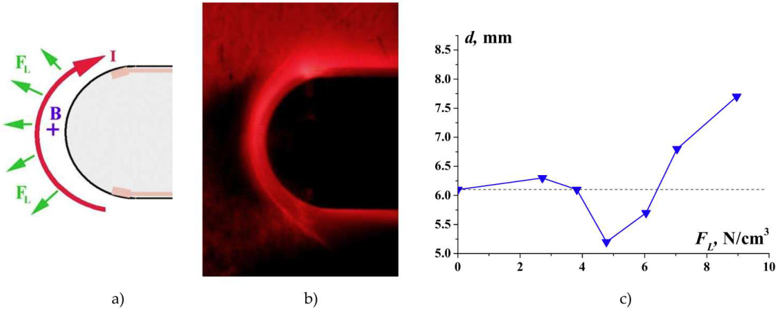
Figure 4.
Scheme of the statement of the problem for the calculations.
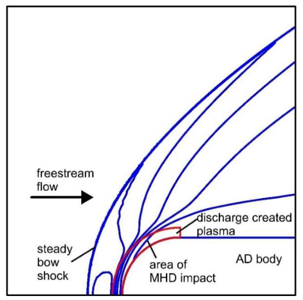
Figure 5.
The position of a part of the front surface of the body on a computational grid (enlarged, every fourth node is shown).
Figure 5.
The position of a part of the front surface of the body on a computational grid (enlarged, every fourth node is shown).
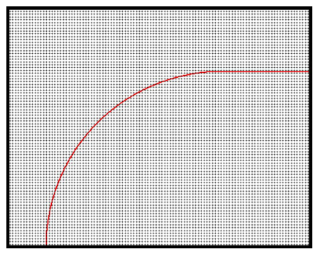
Figure 8.
Comparison of calculated and experimental values of the relative stand-off distance of the steady BSW from the model in xenon for different values and different directions of the Lorentz force FL (a) and in air for FL =0 (b); average temperature values in the plasma region are also given.
Figure 8.
Comparison of calculated and experimental values of the relative stand-off distance of the steady BSW from the model in xenon for different values and different directions of the Lorentz force FL (a) and in air for FL =0 (b); average temperature values in the plasma region are also given.
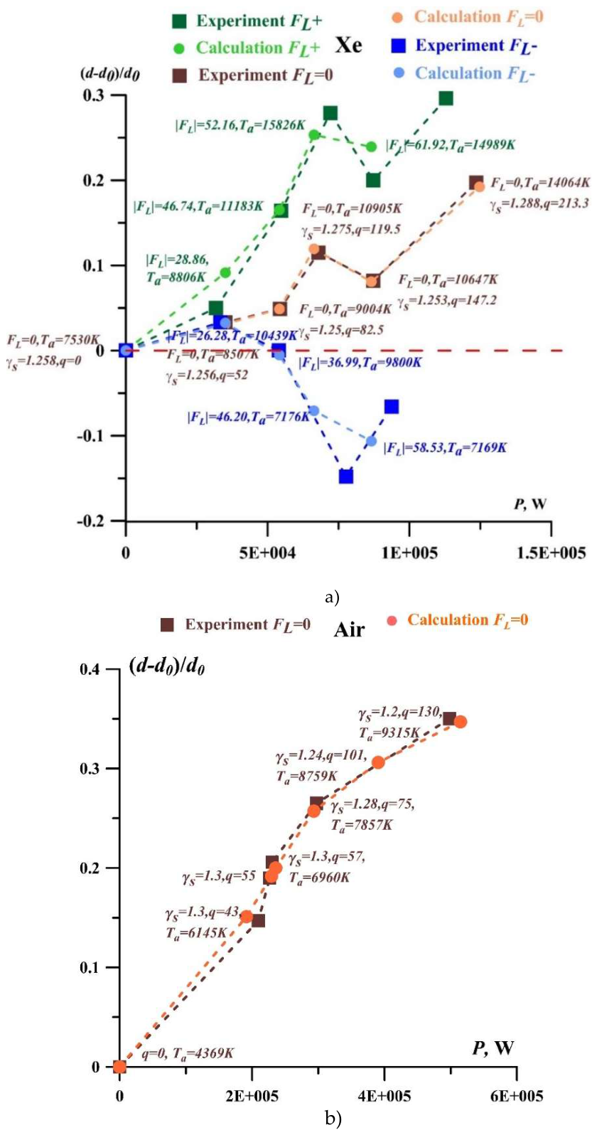
Figure 9.
Input power (a) and electron density (b) in discharge zone vs current in xenon and air.
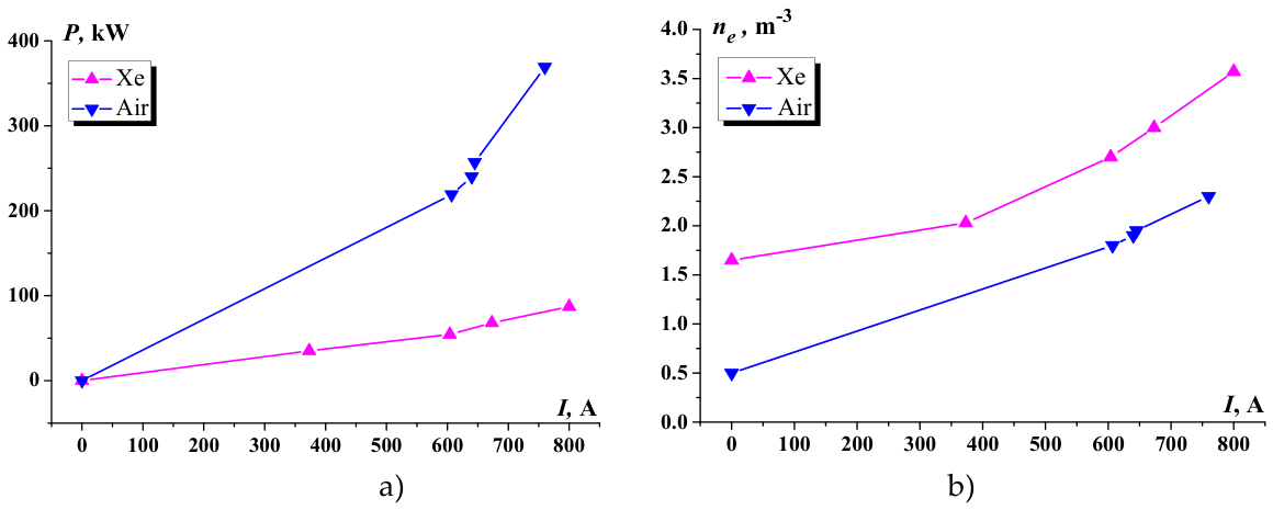
Figure 10.
Adiabatic index: a) according the Burm’s theory for xenon; b) according the Burm’s theory for air; c) calculated from Burm’s theory and numerical modeling vs current for xenon and air.
Figure 10.
Adiabatic index: a) according the Burm’s theory for xenon; b) according the Burm’s theory for air; c) calculated from Burm’s theory and numerical modeling vs current for xenon and air.
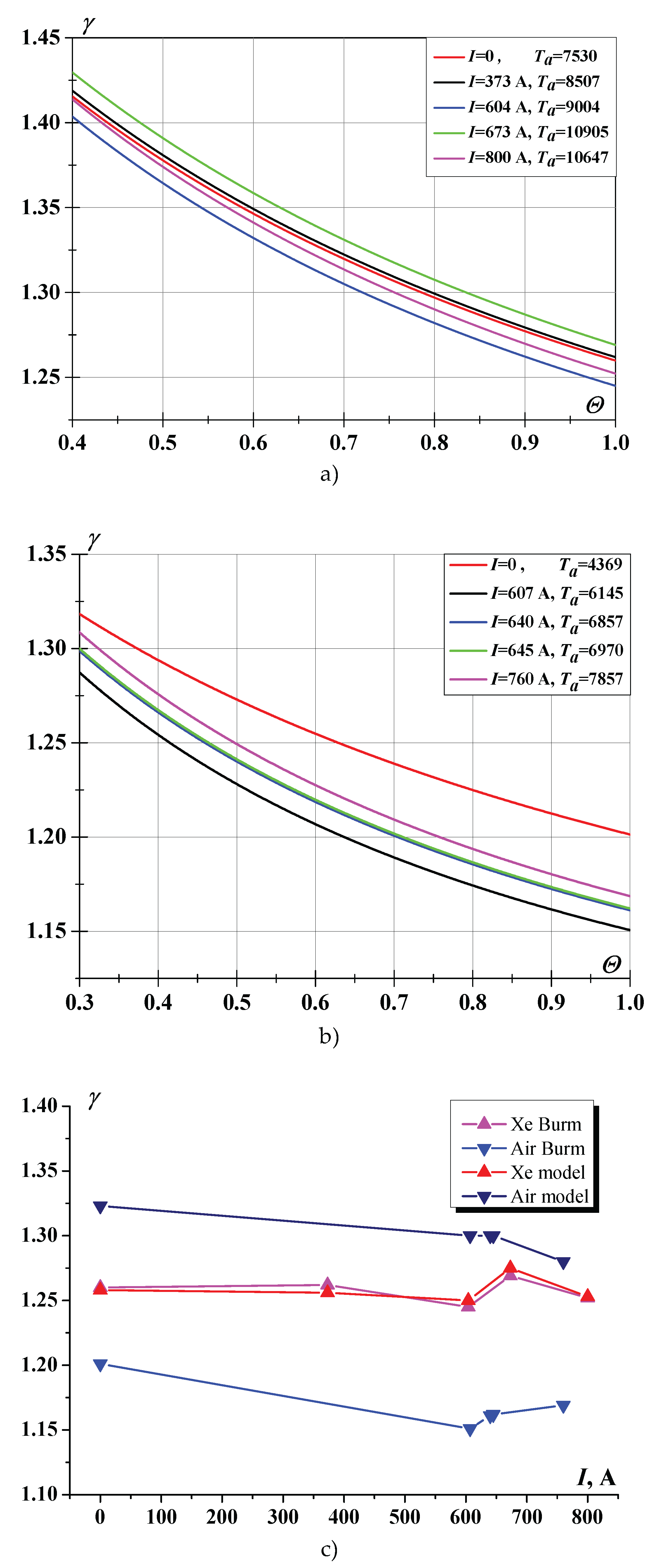
Figure 11.
Input power (a) and electron density (b) in discharge zone vs current.
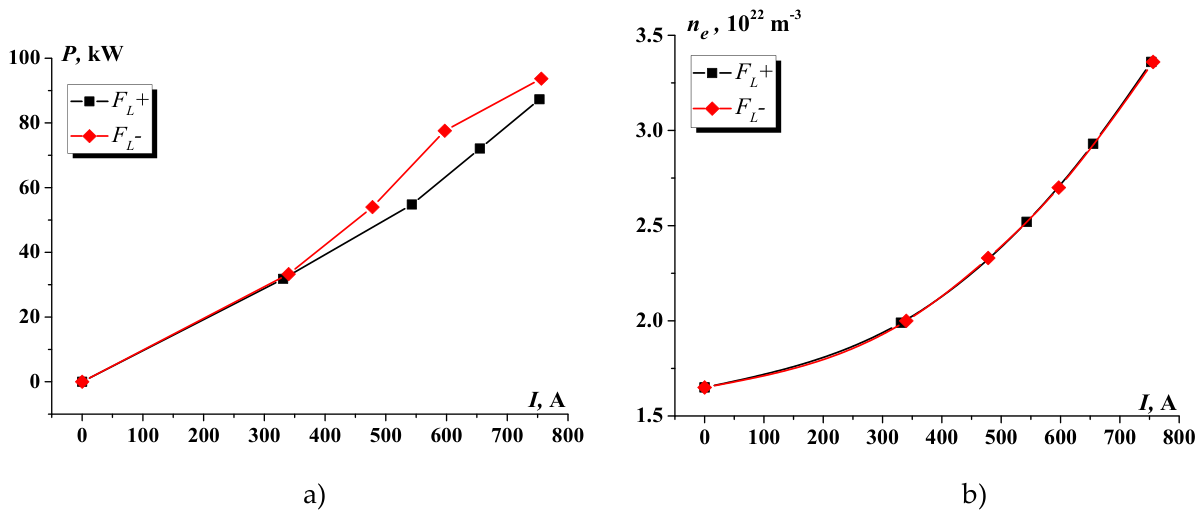
Figure 12.
Calculated adiabatic index according the Burm’s theory for xenon for Case FL+.
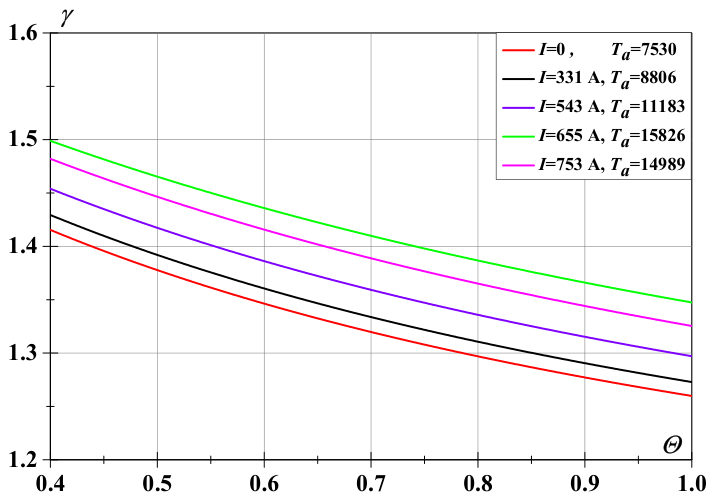
Figure 13.
Calculated adiabatic index according Burm theory for xenon at Case FL-.
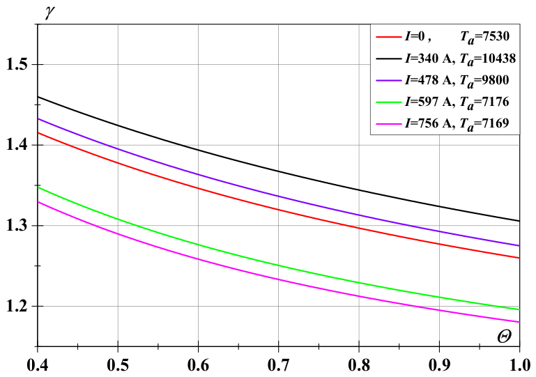
Figure 14.
Dependence of ionization degree (a), electron temperature (b) and adiabatic index (c) on the gas discharge current for Cases FL- and FL+.
Figure 14.
Dependence of ionization degree (a), electron temperature (b) and adiabatic index (c) on the gas discharge current for Cases FL- and FL+.
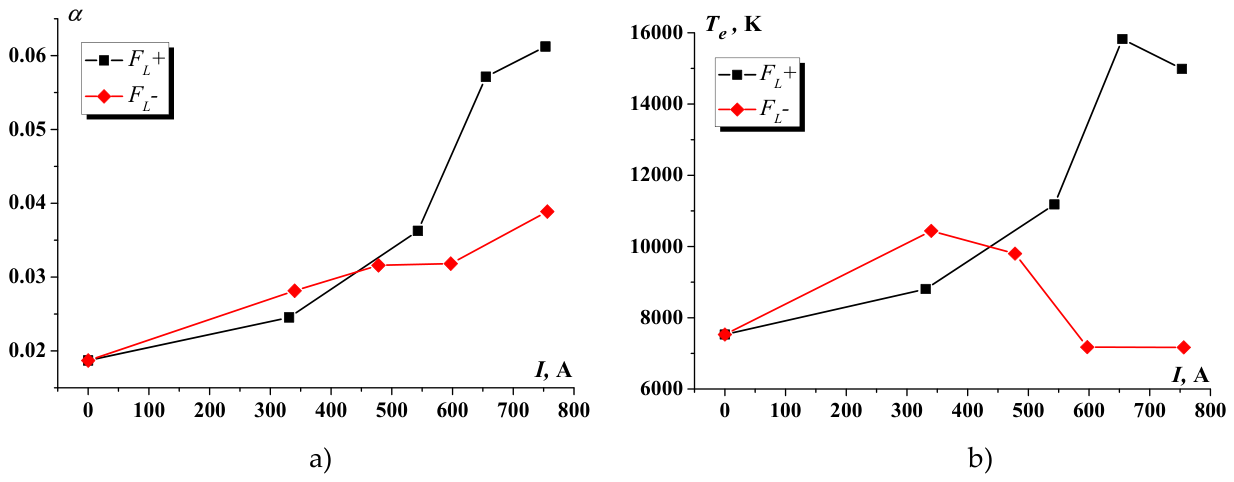
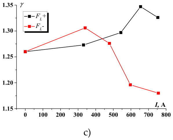

Table 1.
Parameters using and obtained in the calculations for Case FL+ and Case FL-. Working gas – xenon.
Table 1.
Parameters using and obtained in the calculations for Case FL+ and Case FL-. Working gas – xenon.
| I , A | P, Вт | γs [22] | q0 [22] | FL, Case FL+ | qmhd, Case FL+ | |FL|, Case FL- | qmhd, Case FL- |
|---|---|---|---|---|---|---|---|
| 0 | 0 | 1.258 | 0 | 0 | 0 | 0 | 0 |
| 373 | 35099 | 1.256 | 52.0 | 28.86 | 2.45 | 26.28 | 97.24 |
| 604 | 54167 | 1.250 | 82.5 | 46.74 | 51.42 | 36.99 | 55.49 |
| 673 | 66345 | 1.275 | 119.5 | 52.16 | 75.63 | 46.20 | -147.84 |
| 800 | 86577 | 1.253 | 147.2 | 61.92 | 55.73 | 58.53 | -146.33 |
Table 2.
Determining parameters of the oncoming flow and normalizing coefficients for calculations for xenon.
Table 2.
Determining parameters of the oncoming flow and normalizing coefficients for calculations for xenon.
| Xenon | Description | Dimensional value | Dimensionless value | Normalizing coefficient |
| Mach number in the freestream flow | 6.8 | |||
| The Reynolds number Re | 4558.9 | |||
| Prandtl's number Pr | 0.623 | |||
| Adiabatic index in freestream flow γ | 1.217 | |||
| Adiabatic index in the initial plasma region (q=0) γs | 1.258 | |||
| Freestream gas pressure p∞ | 3.1×10³ Pa | 1.0 | pn= p∞ | |
| Freestream gas density ρ∞ | 0.040793 kg/m3 | 1.0 | ρn= ρ∞ | |
| Freestream gas temperature T∞ | 1200 K | 1.0 | Tn= T∞ | |
| Specific power in the plasma region q | See Table 1 | qn= pn/ (tn ρn)= =0.698299×10⁶ kW/kg | ||
| Lorentz force FL | See Table 1 | FLn = ρn un / tn= =0.103332×10⁶ kg/(m2s2) | ||
| Body’s diameter D | 3×10⁻² m | 1.0 | ln=D=3×10⁻² m | |
| Velocity u | 2067.96 m/s | 7.502 | un=(pn / ρn)0.5= 275.668 m/s | |
| Time t | 1.0 | tn=ln/un=108.827 µs |
Table 3.
Determining parameters of the oncoming flow and normalizing coefficients for calculations for air.
Table 3.
Determining parameters of the oncoming flow and normalizing coefficients for calculations for air.
| Air | Description | Dimensional value | Dimensionless value | Normalizing coefficient |
| Mach number in the freestream flow | 4.153 | |||
| The Reynolds number Re | 6763.2 | |||
| Prandtl's number Pr | 0.703 | |||
| Adiabatic index in freestream flow γ | 1.323 | |||
| Adiabatic index in the initial plasma region (q=0) γs | 1.323 | |||
| Freestream gas pressure p∞ | 6790.546 Pа | 1.0 | pn= p∞ | |
| Freestream gas density ρ∞ | 0.017572 kg/m3 | 1.0 | ρn= ρ∞ | |
| Freestream gas temperature T∞ | 1302.024 К | 1.0 | Tn= T∞ | |
| Specific power in the plasma region q0 | 43, 57, 75, 101 | qn= pn/ (tn ρn) | ||
| Lorentz force |FL|kmhd | -10, 0, 10 | FLn = ρn un / tn | ||
| Body’s diameter D | 3×10⁻² m | 1.0 | ln=D=3×10⁻² m | |
| Velocity u | 2969.272 m/s | 4.776 | un=(pn /ρn)0,5= 621.64 m/s | |
| Time t | 1.0 | tn=ln/un=48.26 µs |
Table 4.
The main gas parameters in the impact zone for xenon.
| I | Vpl | P | q | ne | ρa | α | Ta | Θ | γ | (d-d0)/d0 |
|---|---|---|---|---|---|---|---|---|---|---|
| A | V | kW | W/kg | 1022 m-3 | kg/m3 | K | ||||
| 0 | 0 | 0 | 0 | 1.65 | 0.19180 | 0.01871 | 7530 | 1 1 |
1.260 | 0 |
| 373 | 94 | 35.1 | 52 | 2.03 | 0.17759 | 0.02486 | 8507 | 1 | 1.262 | 0.033 |
| 604 | 90 | 54.4 | 82.5 | 2.70 | 0.17275 | 0.03399 | 9004 | 1 | 1.245 | 0.049 |
| 673 | 101 | 68.0 | 119.5 | 3.0 | 0.14608 | 0.04467 | 10905 | 1 | 1.269 | 0.115 |
| 800 | 109 | 87.2 | 147.2 | 3.57 | 0.15475 | 0.05018 | 10647 | 1 | 1.252 | 0.082 |
Table 5.
The main gas parameters in the impact zone for air.
| I | Vpl | P | q | ne | ρa | α | Ta | Θ | γ | (d-d0)/d0 |
|---|---|---|---|---|---|---|---|---|---|---|
| A | V | kW | W/kg | 1022 m-3 | kg/m3 | K | ||||
| 0 | 0 | 0 | 0 | 0.50 | 0.0672 | 0.0035 | 4369 | 0.28 | 1.323 | 0 |
| 607 | 360 | 219 | 43 55 57 75 |
1.80 | 0.0550 | 0.0152 | 6145 | 0.32 | 1.300 | 0.147 |
| 640 | 375 | 240 | 55 57 75 130 |
1.90 | 0.0515 | 0.0172 | 6857 | 0.30 | 1.300 | 0.191 |
| 645 | 399 | 257 | 57 | 1.95 | 0.0511 | 0.0177 | 6960 | 0.30 | 1.300 | 0.206 |
| 760 | 485 | 369 | 75 | 2.30 | 0.0483 | 0.0221 | 7857 | 0.32 | 1.280 | 0.265 |
Table 6.
The main gas parameters in the impact zone at FL+ action.
| I | Vpl | P | q | ne | ρa | α | Ta | Θ | Te | γ | (d-d0)/d0 |
|---|---|---|---|---|---|---|---|---|---|---|---|
| A | V | kW | W/kg | 1022 m-3 | kg/m3 | K | K | ||||
| 0 | 0 | 0 | 0 | 1.65 | 0.19181 | 0.0187 | 7530 | 1 | 7530 | 1.260 | 0 |
| 331 | 96 | 31.8 | 52.0 | 1.99 | 0.17633 | 0.0245 | 8806 | 1 | 8806 | 1.273 | 0.050 |
| 543 | 101 | 54.8 | 82.5 | 2.50 | 0.14987 | 0.0363 | 11183 | 1 | 11183 | 1.297 | 0.164 |
| 655 | 110 | 72.1 | 119.5 | 2.93 | 0.11147 | 0.0571 | 15826 | 1 | 15826 | 1.347 | 0.279 |
| 753 | 116 | 87.3 | 147.2 | 3.36 | 0.11928 | 0.06124 | 14989 | 1 | 14989 | 1.326 | 0.2 |
Table 7.
The main gas parameters in the impact zone at FL- action.
| I | Vpl | P | q | ne | ρa | α | Ta | Θ | Te | γ | (d-d0)/d0 |
|---|---|---|---|---|---|---|---|---|---|---|---|
| A | V | kW | W/kg | 1022 m-3 | kg/m3 | K | K | ||||
| 0 | 0 | 0 | 0 | 1.65 | 0.19181 | 0.0187 | 7530 | 1 | 7530 | 1.260 | 0 |
| 340 | 98 | 33.3 | 52 | 2.00 | 0.15449 | 0.0281 | 10439 | 1 | 10439 | 1.306 | 0.033 |
| 478 | 113 | 54 | 82.5 | 2.34 | 0.16097 | 0.0316 | 9800 | 1 | 9800 | 1.276 | 0 |
| 597 | 130 | 77.6 | 119.5 | 2.70 | 0.18444 | 0.0319 | 7177 | 1 | 7177 | 1.196 | -0.148 |
| 756 | 124 | 93.7 | 147.2 | 3.36 | 0.18789 | 0.0389 | 7169 | 1 | 7169 | 1.180 | -0.066 |
Disclaimer/Publisher’s Note: The statements, opinions and data contained in all publications are solely those of the individual author(s) and contributor(s) and not of MDPI and/or the editor(s). MDPI and/or the editor(s) disclaim responsibility for any injury to people or property resulting from any ideas, methods, instructions or products referred to in the content. |
© 2026 by the authors. Licensee MDPI, Basel, Switzerland. This article is an open access article distributed under the terms and conditions of the Creative Commons Attribution (CC BY) license (http://creativecommons.org/licenses/by/4.0/).
Copyright: This open access article is published under a Creative Commons CC BY 4.0 license, which permit the free download, distribution, and reuse, provided that the author and preprint are cited in any reuse.