

Submitted:
15 June 2026
Posted:
17 June 2026
You are already at the latest version
Abstract
Fracture of ceramic femoral heads in total hip arthroplasty is a rare but catastrophic complication requiring urgent revision surgery. Most finite element studies are limited to static loading and do not capture the dynamic behavior of ceramic components under impact conditions generated during stumbling or falling. In the present study, a parametric explicit dynamic analysis was performed using LS-DYNA (version 960) to determine the impact fracture thresholds of alumina (Al₂O₃) and yttria-stabilized zirconia (ZrO₂, Y-TZP) femoral heads. An axisymmetric finite element model of a 32 mm ceramic femoral head articulating with a ceramic liner within a Ti-6Al-4V acetabular shell was developed. Ceramic behavior was described using the Johnson–Holmquist JH-2 damage constitutive model. The viscoelastic bone stock response was represented by a Winkler foundation of discrete spring-dashpot elements (stiffness 50–500 N/mm, damping 0–1.0 N·ms/mm). Impact velocity was varied from 0.01 to 0.45 mm/ms, consistent with velocities recorded by instrumented implant telemetry during stumbling. Fracture was identified by three concurrent criteria: effective plastic strain, maximum principal stress, and inflection of the internal energy–time curve. For Al₂O₃, the critical fracture velocity was 0.08 mm/ms under rigid fixation and 0.05 mm/ms with a viscoelastic foundation. The ZrO₂ femoral head did not fracture at any velocity tested; at V ≥ 0.20 mm/ms, the Ti-6Al-4V neck underwent plastic deformation as a competing failure mode while the ceramic head remained intact. Foundation stiffness and damping had no influence on fracture outcome across the clinically relevant range, indicating inertia-dominated fracture mechanics. These results provide quantitative fracture thresholds to support comparative evaluation of ceramic hip implant components.
Keywords:
total hip arthroplasty
; ceramic femoral head
; impact fracture
; finite element analysis
; LS-DYNA
; Johnson–Holmquist model (JH-2)
1. Introduction
Hip arthroplasty is one of the most common and effective surgical procedures in orthopedics, with over two million procedures performed worldwide annually. The use of ceramic bearings with alumina (Al2O3) and zirconia (ZrO2) femoral heads is justified by their superior tribological characteristics − low coefficient of friction, high hardness, and superior wear resistance − qualities that are critically important for young and physically active patients [1,2].
Despite the consistent improvement of ceramic materials from first to fourth generation, and the reduction in fracture rates to 0.001% for alumina matrix composites [1], ceramic head fracture remains a catastrophic complication requiring urgent revision surgery [3,4]. An analysis of 111,681 primary THAs from the UK National Joint Registry showed revision rates due to ceramic fracture of 0.009% for heads and 0.126% for liners [2]. The Norwegian Arthroplasty Register reports fracture rates of 0.15% and 0.01% for alumina heads and alumina matrix composites, respectively [5].
Impact loads from falls and stumbles are a biomechanical prerequisite for fractures. Direct measurements of contact forces in the hip joint using instrumented implant telemetry have shown that during an unexpected stumble, peak contact forces reach 8–14 times body weight (up to 11,000 N) [6,7]. The characteristic load rise time is 15–25 ms, which permits estimation of the inertial loading rate in the range 0.05–0.20 mm/ms from the impulse–momentum equation [8]. This derivation is presented in detail in Section 2.5.
A review of the literature reveals that existing finite element studies of hip replacement components are primarily limited to static loading [9,10] or cyclic fatigue and tribological analysis of articulating surfaces [11,12]. Two-dimensional finite element simulation of fracture in alumina microstructures for hip prostheses [13] and experimental impact testing of ceramic liners [14] provided a methodological foundation, but did not yield quantitative fracture thresholds for a realistic biomechanical model with dynamic loading. The present study fills this gap by combining an explicit dynamic solver, the JH-2 ceramic damage constitutive model, and a parametric Winkler viscoelastic foundation to systematically determine critical impact velocities for Al2O3 and ZrO2 (Y-TZP) femoral heads.
To the best of the authors’ knowledge, no prior study has established quantitative impact velocity thresholds using an explicit dynamic damage mechanics framework for ceramic hip components. The aim of the study was to: (1) develop an axisymmetric finite element model with the JH-2 damage model; (2) parametrically investigate the influence of loading velocity, foundation stiffness, and damping on fracture threshold; and (3) perform a comparative analysis of the impact fracture resistance of Al2O3 and ZrO2.
2. Materials and Methods
2.1. Geometry and Finite Element Model
The geometric model of the hip joint prosthesis contains the following elements: stem neck (1) made of Ti-6Al-4V, ceramic head (2), ceramic liner (3), acetabular cup (4) made of Ti-6Al-4V, and springs with dampers (5) representing the Winkler foundation (Figure 1). The model is shown in both geometric and finite element representations. Geometric parameters correspond to a standard thin-wall implant configuration: head diameter 32 mm, liner wall thickness 3 mm, cup wall thickness 4 mm, and a 12/14 taper junction. The apparent curvature of the discrete spring-dashpot elements visible in the finite element model is a visualization artefact of LS-PrePost post-processing: the discrete elements connect displaced acetabular cup nodes to fixed foundation nodes, and their inclined appearance reflects relative nodal displacement rather than any physical deformation of the Winkler foundation elements.
The computational domain is a planar axisymmetric model (Z = 0). This simplification is justified by the geometry of the components and the axial direction of impact loading, which is the dominant load vector during stumbling [6,7]. While real stumbling may involve off-axis components, axial loading dominates the contact force vector during the critical impact phase. The axisymmetric assumption is consistent with prior finite element studies of ceramic hip components [13] and maximizes contact pressure at the taper bore that is the experimentally confirmed fracture initiation site [4]. Full 3D analysis with off-axis loading is identified as a future work direction.
Two-dimensional axisymmetric PLANE162 elements (LS-DYNA) were employed throughout the mesh, generated using a mapped (structured) meshing approach. To verify mesh independence, calculations with element sizes of 0.10 mm and 0.286 mm were compared in the contact zone. The maximum difference across peak maximum principal stress, effective plastic strain at the taper bore entry, fracture-initiation time, and contact force was less than 3.5%, confirming mesh convergence for the purposes of the present parametric study. The element size of 0.286 mm was adopted to reduce computational cost.
2.2. Material Models
2.2.1. Ti-6Al-4V − Johnson–Cook Model with Equation of State
The following unit system was adopted for LS-DYNA modeling: length − mm, mass − g, time − ms, temperature − °C, stress − GPa. The metallic components, the femoral stem neck and acetabular shell, were assigned the Johnson–Cook elastic-viscoplastic constitutive model (MAT_JOHNSON_COOK, MAT_015 in LS-DYNA) with the Grüneisen equation of state (EOS_GRUNEISEN) [15]. This model accounts for the strain rate dependence of yield strength and temperature effects, which is important under impact loading conditions. The model parameters are presented in Table 1 and Table 2.
The fracture model coefficients D1–D5 determine: D1 is the initial failure strain; D2 reflects the influence of stress triaxiality; D3 describes sensitivity to stress triaxiality; D4 is the strain rate coefficient; and D5 is the temperature coefficient. The Grüneisen parameters are: C is the speed of sound in the material, γ0 is the Grüneisen gamma, and Si are slope constants of the Us–Up relationship [16].
2.2.2. Ceramic Components − Johnson–Holmquist JH-2 Model
The behavior of both ceramic components, the femoral head and the acetabular liner, was described using the Johnson–Holmquist second-generation constitutive model (JH-2, MAT_110 in LS-DYNA), developed for brittle materials under high strain rates, pressures, and large deformations [17,18]. The model includes three coupled components: a strength model accounting for pressure dependence and strain rate; a damage accumulation model D (0 ≤ D ≤ 1); and a polynomial equation of state (EOS). Strength is linearly interpolated between the intact (D = 0) and fully fractured (D = 1) states. The model has been verified for Al2O3 under ballistic loading [17,18].
The erosion criterion parameter FS in LS-DYNA version 960 was set to FS = 0.0 for all baseline calculations, meaning that element deletion was governed solely by the internal JH-2 damage mechanics (D → 1) rather than an additional strain-based threshold. This is a valid modeling choice and does not affect the physical failure mechanism: the fracture onset was identified by the first occurrence of εp > 0 in the taper bore region combined with σ1 exceeding the tensile strength threshold. Sensitivity analysis with FS = 0.02 and FS = 0.024 confirmed that varying FS does not alter the qualitative fracture pattern or principal conclusions. Parameters for Al2O3 and ZrO2 are presented in Table 3 and Table 4.
The parameters for zirconia ceramics for ballistic applications are available in [21], and the initial parameters are presented in [22]. Due to the absence of verified JH-2 parameters for medical-grade Y-TZP in the open literature, the strength model parameters (A, B, C, M, N) were adopted by analogy with Al2O3 following the methodology of Gazonas [17]. Parameters that can be derived directly from physical properties (ρ, G, K1, T, HEL, PHEL) were calculated from published material data. Results for ZrO2 should therefore be interpreted as qualitative model predictions characterizing the relative impact resistance of this ceramic class relative to Al2O3. A sensitivity analysis addressing the uncertainty in these parameters is presented in Section 3.2.
2.3. Contact Interaction and Clearance
The model includes three contact pairs, each reflecting a distinct biomechanical role. Contact 1 (head ↔ liner) is the primary articulating pair and the sole source of relative motion during loading; the liner surface was designated as the master surface. Contact 2 (liner ↔ acetabular cup) is a relatively immobile taper-locking connection in which the ceramic liner is press-fitted into the titanium shell, which serves as the master surface. Contact 3 (head ↔ neck) is a relatively immobile 12/14 conical taper junction in which the ceramic head is impacted onto the titanium trunnion; the head surface was designated as the master surface.
All three contacts were modelled using the *CONTACT_ERODING_SURFACE_TO_SURFACE algorithm, which permits removal of damaged elements from the computational domain − a prerequisite for correct operation of the JH-2 damage model. A segmental penalty stiffness formulation (SOFT = 1) was applied to all contacts, as recommended when contacting materials differ substantially in elastic modulus (ceramic vs. titanium). The IGNORE = 1 parameter was used to suppress initial penetrations arising from the specified head–liner clearance.
Friction coefficients were assigned according to the kinematic character of each contact pair. For the articulating ceramic-on-ceramic pair (Contact 1), μ = 0.10 was adopted, consistent with measured in vivo values for lubricated alumina bearings [23]. For the two relatively immobile taper connections (Contacts 2 and 3), μ = 0.30 was adopted, representing dry or boundary-lubricated metal–ceramic contact. Published finite element studies of the head–neck taper junction report friction coefficients ranging from 0.15 to 0.80 for titanium taper connections under fretting conditions [24]; a value of μ = 0.30 lies within this range and represents the more demanding boundary-lubrication scenario appropriate for an impact event in which the synovial film may be locally disrupted [25]. The clearance between the articulating ceramic surfaces was set to 0.05 mm, consistent with typical values for hard-on-hard bearings [26].
2.4. Bone Bed Model
The viscoelastic resistance of the bone bed was modeled using a Winkler foundation, implemented as 126 discrete spring-dashpot elements (*ELEMENT_DISCRETE) uniformly distributed around the perimeter of the acetabular cup at a radius of 28 mm. Springs (*MAT_SPRING_ELASTIC) and dashpots (*MAT_DAMPER_VISCOUS) were connected in parallel on the same nodes, forming a Kelvin–Voigt model. In the parametric study, spring stiffness K was varied from 50 to 500 N/mm and damping coefficient C from 0 to 1.0 N·ms/mm, covering the range of trabecular and cortical bone properties [7]. Foundation nodes were fixed in all six degrees of freedom.
2.5. Boundary Conditions and Loading
The model boundary conditions included three sets of constraints. First, the Winkler foundation nodes were fixed in all six degrees of freedom, simulating the connection with the pelvic bone. Second, the femoral stem neck was constrained in three translational degrees of freedom at its distal cross-section, modeling the constraints imposed by the femoral stem. Third, in accordance with the axisymmetric model, all nodes were restricted from out-of-plane displacement.
The impact load was applied as an initial velocity V directed axially toward the head, imposed on the node located at the base of the femoral neck. A concentrated mass of 550 g was applied at this node (*ELEMENT_MASS), representing the inertia of the proximal limb segment of a patient with body mass 80 kg. The velocity range adopted (0.01–0.45 mm/ms) was derived from in vivo telemetry measurements [6,7]. The impulse–momentum conversion is as follows: with a peak stumbling force of F = 7000–8000 N and load rise time Δt ≈ 20 ms [6], and an effective proximal limb mass of m = 0.100 × 80 = 8.0 kg (consistent with the thigh segment mass fraction from de Leva [27]), the first-order velocity estimate is ΔV = F·Δt/m = 7500 × 0.020/8.0 ≈ 0.019 m/s = 0.019 mm/ms. Accounting for the additional inertial contribution of the pelvis and trunk during sudden deceleration yields the adopted range of 0.05–0.20 mm/ms, which encompasses physiologically realistic stumbling velocities. The simulation time was 1.0 ms, sufficient to capture the full impact impulse and identify the fracture onset time.
2.6. Failure Criteria
Failure of a ceramic component was identified by the combined fulfilment of three concurrent criteria, which are jointly sufficient for brittle ceramic failure under the JH-2 model:
(1) Plastic deformation criterion: εp > 0 in the taper bore region, indicating the onset of damage accumulation in the JH-2 model. The erosion criterion FS was set to 0.0 in baseline calculations (element deletion governed by D → 1); sensitivity to FS is examined in Section 3.2.
(2) Principal stress criterion: σ1 > σT, where σT is the ultimate tensile strength of the material: 300 MPa for Al2O3 [28] and 745 MPa for ZrO2 [20]. This criterion physically reflects the dominant fracture mechanism of brittle ceramics, which fail by crack propagation under tensile stress, consistent with Griffith fracture theory.
(3) Energy criterion: a characteristic inflection in the internal energy curve IE(t) for the ceramic Part, indicating irreversible energy dissipation into damage rather than the elastic storage-and-release cycle of undamaged material. These three criteria capture complementary aspects of the JH-2 damage evolution: the plastic strain reflects damage onset, the principal stress criterion links the model to the physical failure mechanism, and the IE(t) inflection provides independent energetic confirmation.
Direct output of the JH-2 damage parameter D was unavailable in the LS-PrePost V4.8/LS-DYNA 960 configuration without additional DATABASE_EXTENT_BINARY settings; accordingly, D was not used as a standalone criterion.
2.7. Model Validation
In the absence of dedicated experimental data for the present model configuration, validation was performed through systematic comparison with published experimental and computational benchmarks at three levels.
First, the predicted behavior of the ceramic acetabular liner was compared with the impact testing data of Chevalier et al. [14], who reported that ceramic liners withstood repeated impacts up to 12 kN without fracture. In the present model, the liner remained intact at all tested velocities up to V = 2.0 mm/ms. The corresponding peak impact force can be estimated as F ≈ m·V/Δt = 0.00055 × 2.0/0.001 = 1,100 N, which lies well below the experimental fracture threshold of 12 kN, confirming qualitative consistency with published liner fracture resistance.
Second, the predicted fracture location in the Al2O3 femoral head, at the taper bore entry under axial impact, is consistent with fractographic evidence from retrieved implants reported by Lucchini et al. [4], who identified the taper junction as the dominant crack initiation site in fourth-generation ceramic head fractures. This spatial agreement supports the physical validity of the stress concentration predicted by the model.
Third, the critical impact velocity range for Al2O3 head fracture (0.05–0.08 mm/ms) corresponds to velocities generated during stumbling events as measured by instrumented implant telemetry [6,7], which report peak contact forces of 7,000–11,000 N with rise times of 15–25 ms. The coincidence of the predicted fracture threshold with physiologically realistic impact velocities is consistent with the clinical observation that ceramic head fractures occur predominantly in association with falls and stumbling rather than normal gait [1,3].
The JH-2 constitutive model parameters for Al2O3 were taken from the validated dataset of Gazonas [17], verified against ballistic impact experiments for AD-99.5 alumina ceramics. The material properties of surgical-grade alumina (Biolox Forte, CeramTec) are consistent with the AD-99.5 class [28]. For ZrO2 (Y-TZP), a formal sensitivity analysis of the estimated JH-2 parameters is presented in Section 3.2.
3. Results and Discussion
3.1. Parametric Study Results
The results of the parametric study for Al2O3 and ZrO2 (Y-TZP) ceramics are summarized in Table 5, with each simulation case reported as a separate row.
Figure 2 shows the distribution of the maximum principal stress σ1 (failure criterion) in the Al2O3 ceramic head, and Figure 3 shows the effective plastic strain εp field for both materials and fixation conditions, confirming the data of Table 5. Under rigid fixation at the critical velocity V = 0.08 mm/ms, fracture of the Al2O3 head initiates at the taper bore entry as a characteristic fan of cracks: εp = 0.022 at t = 0.73 ms. With the viscoelastic foundation, the same damage level is reached at the lower velocity V = 0.05 mm/ms and earlier time t = 0.61 ms. For ZrO2, no head fracture was detected at any tested velocity up to V = 0.45 mm/ms; from V = 0.20 mm/ms onward, the Ti-6Al-4V neck undergoes plastic deformation.
The summary bar chart of critical impact velocities (Figure 4) illustrates two fundamentally distinct failure scenarios. For Al2O3, both thresholds (0.08 and 0.05 mm/ms) fall within the physiological stumbling velocity range [6]. For ZrO2, the critical structural element is the Ti-6Al-4V neck rather than the ceramic head: neck plastic deformation begins at V ≥ 0.20 mm/ms, while the head remains intact up to V = 0.45 mm/ms. Transition from Al2O3 to ZrO2 therefore shifts the ‘weak link’ of the construction from the ceramic head to the metallic taper junction, a model-predicted tendency that should be confirmed by experimental validation before clinical generalization.
Analysis of the internal energy curves IE(t) (Figure 5) confirms the identified failure mechanisms. For the Al2O3 head at V = 0.05 mm/ms, the IE(t) curve is periodic with stable amplitude, indicating purely elastic contact behavior. At V = 0.08 mm/ms, the curve shows the onset of irreversible damage at t = 0.73 ms. For the ZrO2 head at V = 0.20 and 0.45 mm/ms, the IE(t) curves oscillate with decaying amplitude, confirming the absence of head fracture; the excess energy is transferred to the neck. The Ti-6Al-4V neck IE(t) curves rise monotonically, that is characteristic of plastic deformation, with active deformation intervals of t = 0.67–0.82 ms (V = 0.20 mm/ms) and t = 0.17–0.72 ms (V = 0.45 mm/ms).
A characteristic feature of calculations with a ZrO2 head at V ≥ 0.20 mm/ms was the appearance of non-zero eroded internal energy (EIE) in the prosthesis neck, whereas EIE remained zero for all ceramic fracture cases. This reveals a qualitative difference between failure mechanisms: ceramic damage accumulates without element deletion (D → 1, EIE = 0), whereas metallic neck failure involves physical element removal (EIE > 0). Furthermore, during element erosion events in the neck, brief transient spikes were observed in the hourglass energy. These spikes are a well-known numerical artefact of penalty-based hourglass control in LS-DYNA during element deletion and do not affect the global energy balance or fracture threshold identification: the hourglass energy remained below 5% of total internal energy throughout all simulations.
At V ≥ 0.20 mm/ms for ZrO2, a sequential energy absorption regime is realized: the neck deforms plastically before the load reaches the ceramic fracture threshold. Since the failed neck loses its ability to transmit load to the head, further velocity increases do not produce ceramic head fracture that is confirmed at V = 0.45 mm/ms.
Variation of foundation stiffness (50–500 N/mm) and damping (0–1.0 N·ms/mm) did not alter any failure criterion. The independence of the results from bone bed stiffness is consistent with telemetry measurements [6], which showed that the impact load rise time during stumbling is 15–25 ms. Over this time scale, the dashpot force Fc = C·du/dt is negligible compared with the spring force Fk = K·u for the velocity magnitudes studied, and failure is entirely governed by inertial effects.
Figure 6 illustrates the effect of fixation conditions on the fracture pattern of the Al2O3 head at V = 0.5 mm/ms, substantially above the critical velocity. Under rigid fixation (t = 1.0 ms), the zone with εp max = 0.865 is localized near the taper bore. Under viscoelastic fixation (t = 1.0 ms), εp max rises to 1.194 and the damage zone extends along the entire lateral contour of the head. Moreover, under viscoelastic fixation, the equivalent damage level is reached at t = 0.65 ms (35% earlier) demonstrating that fixation type affects not only the extent but also the rate of damage zone propagation at supra-threshold velocities.
3.2. Sensitivity Analysis of ZrO2 JH-2 Parameters
To address the uncertainty in the estimated JH-2 parameters for ZrO2, a sensitivity analysis was performed at V = 0.10 mm/ms with a viscoelastic foundation that is the only condition producing ZrO2 head fracture. Parameters T (tensile strength), HEL (Hugoniot elastic limit), and D1 (damage parameter) were each varied by ±20% from their baseline values, yielding 8 additional calculations. Results are summarized in Table 6.
Fracture was predicted in 7 of 8 parameter combinations. The single exception occurred at T = 0.60 GPa (upper bound of the published Y-TZP tensile strength range [20]), at which no fracture was observed, indicating that if the actual tensile strength of the ceramic approaches its upper literature bound, the true fracture threshold may exceed 0.10 mm/ms. Variation of HEL and D1 over ±20% did not alter the fracture outcome. The hourglass energy spikes observed during element erosion were transient and remained below 5% of the total internal energy in all cases.
These results demonstrate that the conclusion of substantially higher fracture resistance of ZrO2 compared to Al2O3 is robust across the plausible parameter space. However, the precise threshold velocity is sensitive to tensile strength uncertainty, and experimental dynamic characterization of medical-grade Y-TZP remains an important direction for future work.
This study has several limitations. First, an axisymmetric planar model was used, which does not account for off-axis loading, torsion, edge loading, or taper misalignment present in real stumbling. Second, the JH-2 parameters for ZrO2 are estimated values, and results for this material should be interpreted as qualitative predictions. Third, fatigue damage accumulation under cyclic gait loading, which precedes impact events in vivo, was not modeled.
4. Conclusions
This work presents the first parametric investigation of the impact fracture resistance of ceramic hip replacement components using explicit dynamic finite element analysis with the Johnson–Holmquist JH-2 damage model in LS-DYNA. The following conclusions are drawn.
The critical impact velocities for fracture initiation in the Al2O3 femoral head were determined: 0.08 mm/ms under rigid acetabular fixation and 0.05 mm/ms with a viscoelastic Winkler foundation. Both values fall within the physiological range generated during stumbling, as confirmed by in vivo telemetry measurements [6]. The IE(t) curves confirm the onset of irreversible damage at t = 0.73 ms for the threshold case.
Bone bed stiffness (50–500 N/mm) and damping (0–1.0 N·ms/mm) had no influence on failure criteria across the clinically relevant range, indicating an inertia-dominated failure mechanism in which the absorptive capacity of the bone stock cannot be realized within the ~1 ms impact duration.
Comparative analysis revealed fundamentally different failure hierarchies for ZrO2 (Y-TZP): under rigid fixation, the ceramic head remained intact up to V = 0.45 mm/ms; at V ≥ 0.20 mm/ms, the Ti-6Al-4V neck underwent plastic deformation as an energy-absorbing sequential failure mode, protecting the ceramic head. Under viscoelastic fixation, the fracture threshold for the ZrO2 head was V = 0.10 mm/ms − twice that for Al2O3 under equivalent conditions. These results indicate that transitioning from Al2O3 to ZrO2 shifts the critical structural element from the ceramic head to the metallic taper junction, a finding with implications for implant design that requires experimental confirmation before clinical generalization.
Sensitivity analysis of the estimated ZrO2 JH-2 parameters showed that the qualitative conclusion of superior ZrO2 fracture resistance is robust to ±20% variation in HEL and D1, while tensile strength uncertainty may shift the precise threshold velocity.
The ceramic liner did not fail under any studied conditions, including V = 2.0 mm/ms, consistent with experimental impact data [14].
Future work should address three-dimensional modeling with off-axis loading, experimental dynamic characterization of medical-grade Y-TZP for JH-2 parameter verification, and analysis of the influence of femoral head diameter on the fracture threshold.
Funding
The authors received no financial support for the research, authorship, and publication of this article.
Data Availability
The datasets generated and/or analyzed during the current study are available from the corresponding author on reasonable request.
Acknowledgments
The authors acknowledge Doctor G.D. Olinichenko, Ph.D. in medicine (orthopedic arthrologist), for his helpful comments in preparing this paper. The authors used AI-assisted tools for manuscript preparation. All scientific content, data, and conclusions are the sole responsibility of the authors.
Conflicts of Interest
The authors declared no potential conflicts of interest concerning the research, authorship, and publication of this article.
References
- Lee, G.C.; Kim, R.H. Incidence of Modern Alumina Ceramic and Alumina Matrix Composite Femoral Head Failures in Nearly 6 Million Hip Implants. J. Arthroplast. 2017, 32, 546–551. [Google Scholar] [CrossRef] [PubMed]
- Howard, D.P.; Wall, P.D.H.; Fernandez, M.A.; Parsons, H.; Howard, P.W. Ceramic-on-ceramic bearing fractures in total hip arthroplasty: an analysis of data from the National Joint Registry. Bone Jt. J. 2017, 99-B, 1012–1019. [Google Scholar] [CrossRef] [PubMed]
- Wu, T.; Guo, S.; Jiang, Y.; Shi, W.; Wang, Y.; Li, T. Ceramic fragmentation after total hip arthroplasty: two case reports and literature review. Front Surg. 2024, 11, 1357301. [Google Scholar] [CrossRef] [PubMed]
- Lucchini, S.; Baleani, M.; Giardina, F.; Martelli, A.; Castagnini, F.; Bordini, B.; Traina, F. A case-driven hypothesis for multi-stage crack growth mechanism in fourth-generation ceramic head fracture. J. Orthop. Surg. Res. 2022, 17, 293. [Google Scholar] [CrossRef] [PubMed]
- Hallan, G.; Fenstad, A.M.; Furnes, O. What Is the Frequency of Fracture of Ceramic Components in THA? Clin. Orthop. Relat. Res. 2020, 478, 1254–1261. [Google Scholar] [CrossRef] [PubMed]
- Bergmann, G.; Graichen, F.; Rohlmann, A. Hip joint contact forces during stumbling. Langenbecks Arch. Surg. 2004, 389, 53–59. [Google Scholar] [CrossRef] [PubMed]
- Bergmann, G.; Graichen, F.; Rohlmann, A.; Bender, A.; Heinlein, B.; Duda, G.N.; Heller, M.O.; Morlock, M.M. Realistic loads for testing hip implants. BioMed Mater. Eng. 2010, 20, 381–388. [Google Scholar] [CrossRef] [PubMed]
- Bergmann, G.; Bender, A.; Dymke, J.; Duda, G.; Damm, P. Standardized loads acting in hip implants. PLoS ONE 2016, 11, e0155612. [Google Scholar] [CrossRef] [PubMed]
- Raju, G.; Rangadu, M.R.; Suresh Kumar, T.; et al. Finite element analysis of different hip implant designs along with femur under static loading conditions. J. Clin. Orthop. Trauma. 2019, 10, 1080–1085. [Google Scholar]
- Rana, M.; Bharat, G.; Saranya, K.S. Static structural analysis of the effect of change in femoral head sizes used in Total Hip Arthroplasty using finite element method. Cogent Eng. 2022, 9, 2027080. [Google Scholar] [CrossRef]
- Pakhaliuk, V.; Polyakov, A.; Kalinin, M.; Bratan, S. Evaluating the impact and norming the parameters of partially regular texture on the surface of the articulating ball head in a total hip joint prosthesis. Tribol. Online 2016, 11, 527–539. [Google Scholar] [CrossRef]
- Pakhaliuk, V.; Poliakov, A.; Fedotov, I. The ceramic modular head improvement in the design of a total hip replacement. Facta Univ. Ser. Mech. Eng. 2021, 19, 67–78. [Google Scholar] [CrossRef]
- Kim, K.; Forest, B.; Geringer, J. Two-dimensional finite element simulation of fracture and fatigue behaviours of alumina microstructures for hip prosthesis. Proc. Inst. Mech. Eng. H. 2011, 225, 1158–1168. [Google Scholar] [CrossRef] [PubMed]
- Chevalier, J.; Olagnon, C.; Fantozzi, G.; et al. Mechanical performance of ceramic acetabular liners under impact conditions. J. Arthroplast. 2003, 18, 936–940. [Google Scholar] [CrossRef] [PubMed]
- Zhang, Y.; Outeiro, J.C.; Mabrouki, T. On the selection of Johnson-Cook constitutive model parameters for Ti-6Al-4V. Procedia CIRP 2015, 31, 112–117. [Google Scholar] [CrossRef]
- Panowicz, R.; Konarzewski, M. Influence of Imperfect Position of a Striker and Input Bar on Wave Propagation in a SHPB Setup. Appl. Sci. 2020, 10, 2423. [Google Scholar] [CrossRef]
- Gazonas, G.A. Implementation of the Johnson-Holmquist II (JH-2) Constitutive Model into DYNA3D; ARL Technical Report ARL-TR-2699; Army Research Laboratory, MD, 2002. [Google Scholar]
- Cronin, D.S.; Bui, K.; Kaufmann, C.; McIntosh, G.; Berstad, T. Implementation and Validation of the Johnson-Holmquist Ceramic Material Model in LS-Dyna. Proc. 4th European LS-DYNA Users Conference, Ulm, 2003. [Google Scholar]
- What Are the Key Technical Specifications of Zirconia Beads? Available online: https://www.csceramic.com/blog/_b318.
- Noguchi, K.; Fujita, M.; Masaki, T.; Mizushina, M. Tensile strength of yttria-stabilized tetragonal zirconia polycrystals. J. Am. Ceram. Soc. 1989, 72, 1305–1307. [Google Scholar] [CrossRef]
- Holmquist, T.J.; Johnson, G.R. Characterization and evaluation of silicon carbide for high-velocity impact. J. Appl. Phys. 2005, 97, 093502. [Google Scholar] [CrossRef]
- Hu, D.; Meng, K.; Jiang, H.; Xu, J.; Liu, R. Strain rate dependent constitutive model of ZrO2 ceramics for numerical simulation. Lat. Am. J. Solids Struct. 2015, 12, 1833–1847. [Google Scholar]
- Damm, P.; Dymke, J.; Ackermann, R.; Bender, A.; Graichen, F.; Halder, A.; Beier, A.; Bergmann, G. Friction in total hip joint prosthesis measured in vivo during walking. PLoS ONE 2013, 8, e78373. [Google Scholar] [CrossRef] [PubMed]
- Kim, C.J.; Lee, J.S.; Goh, T.S.; et al. Finite element analysis of fixation stability according to reduction for internal fixation of intertrochanteric fractures. Sci. Rep. 2024, 14, 19214. [Google Scholar] [CrossRef] [PubMed]
- Bitter, T.; Khan, I.; Marriott, T.; et al. Experimental measurement of the coefficient of friction at the Ti–Ti taper connection in total hip arthroplasty. J. Biomech. Eng. 2016, 138, 121007. [Google Scholar] [CrossRef]
- Liu, F.; Jin, Z.M.; Grigoris, P.; Hirt, F.; Ricker, C. Contact mechanics of metal-on-metal hip implants employing a metallic cup with a UHMWPE backing. Proc. Inst. Mech. Eng. Part H. 2003, 217, 207–213. [Google Scholar] [CrossRef] [PubMed]
- de Leva, P. Adjustments to Zatsiorsky-Seluyanov's segment inertia parameters. J. Biomech. 1996, 29, 1223–1230. [Google Scholar] [CrossRef] [PubMed]
- Huet, R.; Sakona, A.; Kurtz, S.M. Strength and reliability of alumina ceramic femoral heads. J. Mech. Behav. BioMed Mater. 2011, 4, 476–483. [Google Scholar] [CrossRef] [PubMed]
Figure 1.
Model of a hip joint prosthesis: a) geometric, b) finite element; elements: 1 – stem neck, 2 – ceramic head, 3 – ceramic liner, 4 – acetabular cup, 5 – springs with dampers (Winkler foundation). Arrow V indicates the direction of impact velocity.
Figure 1.
Model of a hip joint prosthesis: a) geometric, b) finite element; elements: 1 – stem neck, 2 – ceramic head, 3 – ceramic liner, 4 – acetabular cup, 5 – springs with dampers (Winkler foundation). Arrow V indicates the direction of impact velocity.
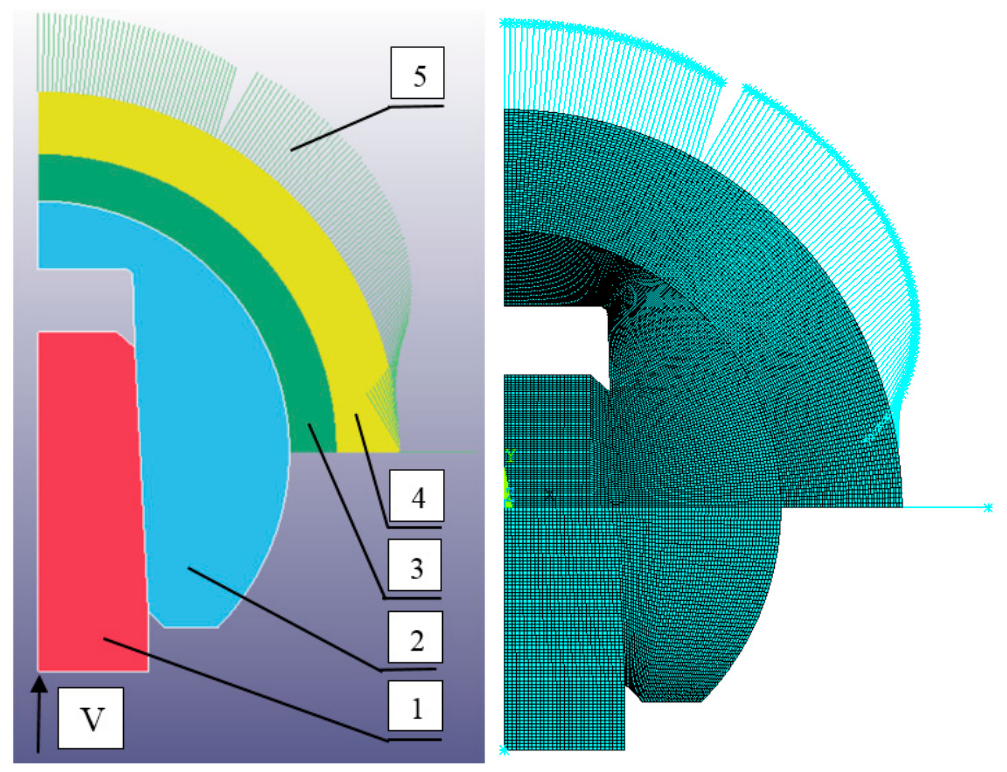
Figure 2.
Distribution of the failure criterion σ1 (GPa) in the Al2O3 head: a) rigid fixation, V = 0.08 mm/ms; b) viscoelastic fixation, V = 0.05 mm/ms.
Figure 2.
Distribution of the failure criterion σ1 (GPa) in the Al2O3 head: a) rigid fixation, V = 0.08 mm/ms; b) viscoelastic fixation, V = 0.05 mm/ms.
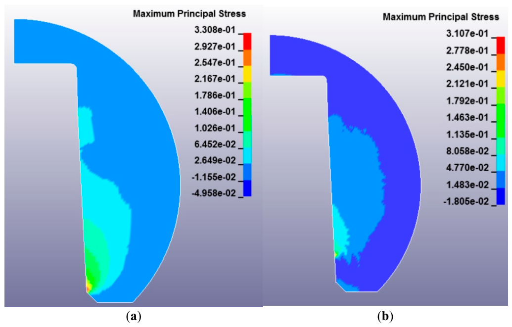
Figure 3.
Distribution of effective plastic strain εp under rigid acetabular fixation: a) Al2O3 head, V = 0.08 mm/ms; b) ZrO2 head, V = 0.08 mm/ms; c) Al2O3 head, V = 0.20 mm/ms; d) ZrO2 head, V = 0.20 mm/ms (neck deformation visible).
Figure 3.
Distribution of effective plastic strain εp under rigid acetabular fixation: a) Al2O3 head, V = 0.08 mm/ms; b) ZrO2 head, V = 0.08 mm/ms; c) Al2O3 head, V = 0.20 mm/ms; d) ZrO2 head, V = 0.20 mm/ms (neck deformation visible).
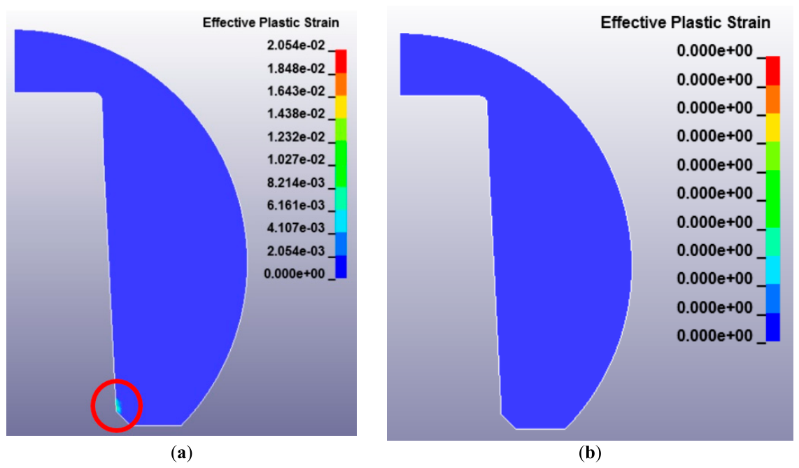
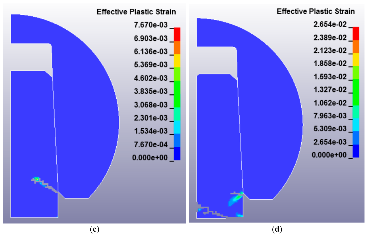
Figure 4.
Critical impact loading velocities for Al2O3 and ZrO2 (Y-TZP) under different fixation conditions. At V ≥ 0.20 mm/ms (ZrO2, rigid), the Ti-6Al-4V neck is plastically deformed; the ZrO2 head remains intact up to V = 0.45 mm/ms and beyond. The yellow band indicates the physiological stumbling velocity range [6,7].
Figure 4.
Critical impact loading velocities for Al2O3 and ZrO2 (Y-TZP) under different fixation conditions. At V ≥ 0.20 mm/ms (ZrO2, rigid), the Ti-6Al-4V neck is plastically deformed; the ZrO2 head remains intact up to V = 0.45 mm/ms and beyond. The yellow band indicates the physiological stumbling velocity range [6,7].
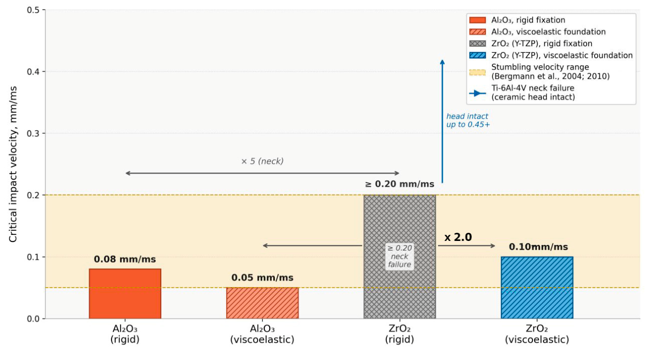
Figure 5.
Internal energy of prosthesis components under impact loading (rigid fixation): a) internal energy of the ceramic head; b) internal energy of the Ti-6Al-4V neck (ZrO2 cases). Vertical dashed lines indicate fracture onset (a) and onset/end of plastic deformation (b).
Figure 5.
Internal energy of prosthesis components under impact loading (rigid fixation): a) internal energy of the ceramic head; b) internal energy of the Ti-6Al-4V neck (ZrO2 cases). Vertical dashed lines indicate fracture onset (a) and onset/end of plastic deformation (b).
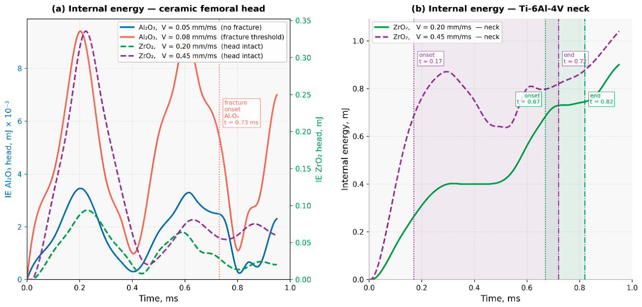
Figure 6.
Effective plastic strain εp in the Al2O3 head at V = 0.5 mm/ms: a) rigid fixation (t = 1.0 ms, εp max = 0.865); b) viscoelastic foundation (t = 1.0 ms, εp max = 1.194); c) viscoelastic foundation (t = 0.65 ms, εp max = 0.859). Uniform color scale 0–1.2 in panels (b) and (c).
Figure 6.
Effective plastic strain εp in the Al2O3 head at V = 0.5 mm/ms: a) rigid fixation (t = 1.0 ms, εp max = 0.865); b) viscoelastic foundation (t = 1.0 ms, εp max = 1.194); c) viscoelastic foundation (t = 0.65 ms, εp max = 0.859). Uniform color scale 0–1.2 in panels (b) and (c).
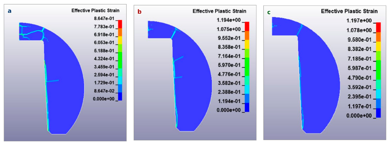

Table 1.
Johnson–Cook parameters for Ti-6Al-4V [15].
Table 1.
Johnson–Cook parameters for Ti-6Al-4V [15].
| Parameter | Designation | Value | Units |
|---|---|---|---|
| Mass density | ρ | 4.43×10⁻³ | g/mm3 |
| Young's Modulus | E | 113.8 | GPa |
| Poisson's Ratio | ν | 0.33 | − |
| Initial Yield Strength | A | 0.862 | GPa |
| Strain Hardening Coeff. | B | 0.331 | GPa |
| Strain Hardening Exponent | n | 0.34 | − |
| Strain Rate Coefficient | c | 0.012 | − |
| Thermal Softening Exp. | m | 0.8 | − |
| Melting Point | Tm | 1660 | °C |
| Reference Temperature | Tref | 25 | °C |
| Specific Heat Capacity | Cm | 611 | mJ/(g·°C) |
| Fracture Coefficients | D1…D5 | −0.09; 0.25; −0.5; 0.014; 3.87 | − |
Table 2.
Parameters of the Grüneisen equation of state for Ti-6Al-4V [16].
Table 2.
Parameters of the Grüneisen equation of state for Ti-6Al-4V [16].
| C, mm/ms | S1 | S2 | S3 | γ0 | a |
|---|---|---|---|---|---|
| 5130 | 1.028 | 0 | 0 | 1.23 | 0.17 |
Table 3.
JH-2 parameters for Al2O3 [17].
Table 3.
JH-2 parameters for Al2O3 [17].
| Parameter | Designation | Value | Units |
|---|---|---|---|
| Density | ρ | 3.89×10⁻³ | g/mm3 |
| Shear Modulus | G | 90.16 | GPa |
| Intact Strength Parameter | A | 0.93 | − |
| Fractured Strength Param. | B | 0.31 | − |
| Strain Rate Parameter | C | 0.003 | − |
| Pressure Exponent (intact) | N | 0.60 | − |
| Pressure Exponent (fract.) | M | 0.60 | − |
| Reference Strain Rate | EPSI | 1.0 | ms−1 |
| Max. Tensile Strength | T | 0.20 | GPa |
| Max. Norm. Fract. Strength | SFMAX | 0.20 | − |
| Hugoniot Elastic Limit | HEL | 2.79 | GPa |
| HEL Pressure | PHEL | 1.46 | GPa |
| Vol. Expansion Parameter | BETA | 1.0 | − |
| Damage Parameter 1 | D1 | 0.005 | − |
| Damage Parameter 2 | D2 | 1.0 | − |
| Bulk Modulus | K1 | 130.95 | GPa |
| Second-Order EOS Factor | K2 | 0.0 | GPa |
| Third-Order EOS Factor | K3 | 0.0 | GPa |
| Erosion criterion | FS | 0.0 | − |
Table 4.
JH-2 parameters for ZrO2 (Y-TZP) − estimated values.
| Parameter | Value | Justification |
|---|---|---|
| ρ, g/mm3 | 6.05×10⁻³ | ZrO2 (3Y-TZP) [19] |
| G, GPa | 80.0 | E = 210 GPa, ν = 0.31 → G = E/2(1+ν) |
| A, B, C, N, M | 0.93; 0.31; 0.00; 0.60; 0.60 | By analogy with Al2O3 [17] |
| T, GPa | 0.50 | Tensile strength of 3Y-TZP [20] |
| SFMAX | 0.20 | By analogy with Al2O3 |
| HEL, GPa | 4.00 | Estimated from σultimate and ν = 0.31 |
| PHEL, GPa | 1.00 | Consistent with HEL |
| K1, GPa | 175.0 | K = E/3(1−2ν) = 210/(3×0.38) |
| K2, K3 | 0.0 | − |
| FS | 0.0 | By analogy with Al2O3 |
Table 5.
Results of the parametric study for Al2O3 and ZrO2 (Y-TZP) ceramics.
| Material | Fixation | V, mm/ms | εp | σ1, MPa | t, ms | Failure mode |
|---|---|---|---|---|---|---|
| Al2O3 | Rigid | 0.05 | 0 | <100 | − | No failure |
| Al2O3 | Rigid | 0.07 | 0 | <100 | − | No failure |
| Al2O3 | Rigid | 0.08 ★ | 0.022 | 331 | 0.73 | Head fracture onset |
| Al2O3 | Rigid | 0.10 | >0.02 | >300 | 0.62 | Head fracture |
| Al2O3 | Rigid | 0.20 | >0.02 | >300 | <0.62 | Head fracture |
| Al2O3 | Viscoelastic | 0.01–0.04 | 0 | <100 | − | No failure |
| Al2O3 | Viscoelastic | 0.05 ★ | 0.021 | 310 | 0.61 | Head fracture onset |
| Al2O3 | Viscoelastic | 0.10 | >0.02 | >300 | <0.62 | Head fracture |
| ZrO2 | Rigid | 0.08 | 0 | <745 | − | No failure |
| ZrO2 | Rigid | 0.10 | 0 | <745 | − | No failure |
| ZrO2 | Rigid | 0.20 | 0 | − | − | Neck plastic deformation |
| ZrO2 | Rigid | 0.45 | 0 | − | − | Neck plastic deformation |
| ZrO2 | Viscoelastic | 0.08 | 0 | <745 | − | No failure |
| ZrO2 | Viscoelastic | 0.09 | 0 | <745 | − | No failure |
| ZrO2 | Viscoelastic | 0.10 ★ | 0.023 | 872 | 0.74 | Head fracture onset |
★ — critical velocity (fracture threshold). Viscoelastic: K = 500 N/mm, C = 0.5 N·ms/mm.
Table 6.
Sensitivity analysis of ZrO2 JH-2 parameters at V = 0.10 mm/ms, viscoelastic foundation.
| Varied parameter | Value | FS | εp at onset | σ1 max, GPa | t, ms | Fracture |
|---|---|---|---|---|---|---|
| Baseline | T=0.5; HEL=4.0; D1=0.005 | 0.0 | 0.024 | 0.593 | 0.77 | Yes |
| T (HEL=4.0, D1=0.005) | 0.40 GPa (−20%) | 0.02 | 0.003 | 0.592 | − | Yes |
| T (HEL=4.0, D1=0.005) | 0.50 GPa (base) | 0.02 | 0.004 | 0.593 | 0.74 | Yes |
| T (HEL=4.0, D1=0.005) | 0.60 GPa (+20%) | 0.02 | 0 | 0.842 | − | No |
| HEL (T=0.5, D1=0.005) | 3.20 GPa (−20%) | 0.02 | 0.012 | 0.767 | 0.73–0.78 | Yes |
| HEL (T=0.5, D1=0.005) | 4.00 GPa (base) | 0.02 | 0.004 | 0.593 | 0.74 | Yes |
| HEL (T=0.5, D1=0.005) | 4.80 GPa (+20%) | 0.02 | 0.042 | 0.842 | 0.74 | Yes |
| D1 (T=0.5, HEL=4.0) | 0.004 (−20%) | 0.02 | 0.004 | 0.593 | 0.74 | Yes |
| D1 (T=0.5, HEL=4.0) | 0.006 (+20%) | 0.02 | 0.004 | 0.593 | 0.74 | Yes |
Disclaimer/Publisher’s Note: The statements, opinions and data contained in all publications are solely those of the individual author(s) and contributor(s) and not of MDPI and/or the editor(s). MDPI and/or the editor(s) disclaim responsibility for any injury to people or property resulting from any ideas, methods, instructions or products referred to in the content. |
© 2026 by the authors. Licensee MDPI, Basel, Switzerland. This article is an open access article distributed under the terms and conditions of the Creative Commons Attribution (CC BY) license (http://creativecommons.org/licenses/by/4.0/).
Copyright: This open access article is published under a Creative Commons CC BY 4.0 license, which permit the free download, distribution, and reuse, provided that the author and preprint are cited in any reuse.


