

Submitted:
11 June 2026
Posted:
12 June 2026
You are already at the latest version
Abstract
This article presents the development and experimental validation of a Wi-Fi-based distributed system for monitoring the technical condition of building structures. The proposed approach is based on a hybrid mesh/ad hoc network architecture, in which sensor nodes function as autonomous cyber-physical elements and communicate via IEEE 802.11 without relying on a centralized wired infrastructure.
The research includes the design of the structural and functional system architec-ture, the development of a distributed data transmission algorithm, and the imple-mentation of a multi-sensor monitoring platform that integrates distance, magnetom-etry, and environmental sensors. A mathematical model of the network is introduced, and the key communication parameters affecting the system’s operation are analyzed.
Experimental validation was conducted using 500 consecutive measurements, and a comparative analysis of wired and wireless data acquisition methods was performed. The evaluation was based on statistical metrics such as the mean absolute error (MAE) and root mean square error (RMSE), as well as time-series analysis. The results show that the wireless communication channel reliably preserves the temporal dynamics of the measured parameters without data loss. The highest accuracy was achieved for distance sensors and the DHT22 temperature channel, while magnetometric sensors and humidity measurements exhibited moderate variability depending on sensor sen-sitivity and transmission conditions.
The proposed system demonstrates high stability, scalability, and fault tolerance, confirming the feasibility of using standard Wi-Fi technology for monitoring the tech-nical condition of building structures. The developed architecture can be effectively applied not only in the construction industry but also in related fields, such as envi-ronmental monitoring, energy systems, and smart infrastructure applications.
Keywords:
structural health monitoring (SHM)
; wireless sensor networks (WSNs)
; IEEE 802.11
; distributed monitoring
; sustainable development
; remote sensing
; structural diagnostics
1. Introduction
Structural health monitoring (SHM) systems play a crucial role in ensuring the safety and reliability of engineering structures, particularly in the context of increasingly complex infrastructure and aging assets. Continuous monitoring of structural parameters such as displacement, strain, environmental conditions, and magnetic field variations enables the early detection of defects, including cracks and material degradation, thereby reducing the risk of structural damage and associated economic losses.
Traditionally, SHM systems rely on wired sensor networks, which provide high data reliability but suffer from significant limitations, such as high installation costs, limited scalability, and reduced deployment flexibility. The rapid development of wireless communication technologies has led to the emergence of wireless sensor networks (WSNs) as a promising alternative, offering advantages such as ease of installation, reduced infrastructure requirements, and the capability for distributed data processing. However, WSNs still face a number of challenges related to data transmission stability, synchronization, power consumption, and maintaining signal integrity during long-term monitoring.
In recent years, Wi-Fi-based solutions have gained attention as a practical and widely available communication technology for distributed monitoring systems. Unlike specialized low-power protocols, Wi-Fi provides high throughput and compatibility with existing network infrastructure, enabling seamless integration with cloud platforms and remote data processing systems. Furthermore, the use of standard IEEE 802.11 networks for SHM tasks requires careful evaluation, particularly in terms of reliability, data consistency, and the impact of wireless transmission on measurement accuracy.
The novelty of this research lies in the development and experimental validation of a distributed monitoring architecture based on standard Wi-Fi connectivity, as well as in the integration of heterogeneous sensors within a unified data acquisition and transmission framework. Unlike traditional approaches, which rely on proprietary or specialized communication protocols, the proposed system uses widely available network technologies to achieve flexibility, scalability, and ease of deployment. Furthermore, this work presents a comprehensive comparative analysis of wired and wireless data collection methods for multiple sensor types, including distance sensors, magnetometers, and environmental sensors, allowing for a detailed assessment of data transmission stability and measurement accuracy under specific experimental conditions.
The primary objective of this study is to evaluate the feasibility of using a Wi-Fi-based distributed system for structural monitoring by analyzing the stability, accuracy, and reliability of measurement data transmitted over wireless channels. To achieve this goal, a multi-sensor monitoring system was developed, a distributed data transmission algorithm was implemented, and an experimental study based on 500 consecutive measurements was conducted. The results were analyzed using statistical metrics and time-series comparison methods to evaluate the consistency between wired and wireless data acquisition methods.
2. Literature Review
General issues of structural monitoring and distributed systems have been widely studied in the works of Worden, K., Farrar C. R., Manson G., Park G., Fan W., Qiao P., Balageas D., Fritzen C.-P., and Güemes A. and others [1,2,3,4,5].
Over the past two decades, research in the field of structural health monitoring (SHM) has shifted from wired centralized systems to distributed wireless platforms; however, several fundamental problems remain unresolved. Early review studies demonstrated the potential of wireless sensor networks (WSNs) for SHM applications, highlighted advantages such as reduced cabling costs and the possibility of local data preprocessing, and identified major limitations regarding power consumption, time synchronization, and data transmission reliability [6,7].
Comprehensive reviews of SHM systems have identified common architectural approaches and algorithms for fault detection, and shown that many existing implementations remain at the prototype or demonstration stage. Important issues, such as effective power management, reliable transmission of high-frequency time-series data, and the scalability of laboratory environments to real-world deployments, have not yet been fully resolved [8,9]. In particular, bandwidth limitations and the requirement for precise time synchronization between sensor nodes significantly hinder the use of distributed modal analysis methods and correlation-based algorithms in large-scale monitoring systems.
A separate line of research focuses on using Wi-Fi not only as a communication medium but also as a detection method by analyzing channel parameters such as the received signal strength indicator (RSSI) and channel state information (CSI). Reviews of Wi-Fi-based sensor systems demonstrate the high potential of CSI-based approaches for detecting events and environmental changes due to their sensitivity to multipath propagation effects. Research in this area also demonstrates the possibility of preprocessing data on low-cost edge devices (e.g., ESP32), making Wi-Fi an attractive solution for efficient and large-scale monitoring applications [10].
Nevertheless, Wi-Fi-based approaches exhibit several limitations in structural health monitoring. These include the high sensitivity of CSI measurements to environmental changes, such as temperature fluctuations, ventilation conditions, and human movement, as well as platform-dependent access to CSI metrics and the need for frequent calibration and adaptation of machine learning models. These factors make it difficult to reliably interpret channel characteristics as indicators of structural damage in long-term monitoring systems without the use of additional filtering and drift compensation methods [11].
Practical field deployment of SHM systems in large-scale structures, such as bridges and buildings, confirms the value of continuous monitoring while highlighting the limitations of traditional centralized and wired approaches. These limitations include high installation costs as well as low flexibility during repair or reconfiguration processes. Field studies further point to issues such as signal transmission delays, scaling difficulties for large numbers of sensor nodes, and the vulnerability of centralized architectures to local failures [12].
Recent studies have provided advanced solutions for structural health monitoring. For example, Abruzzi et al. [13] proposed a state-of-the-art monitoring system that integrates various sensors, including accelerometers, strain gauges, and other measuring devices. The proposed system was experimentally tested for detailed structural monitoring and allows for real-time comparison of measured data with the results of the corresponding quantitative structural model. Additionally, the system supports feedback mechanisms, enabling a transition from traditional monitoring to advanced “Intelligent monitoring” paradigms.
A monitoring approach presented in [14] describes a technical solution intended for assessing and predicting the condition of engineering structures, including bridge supports, hydraulic facilities, berth structures, and building elements, based on tilt measurements relative to the horizontal plane. The proposed system combines a bubble level, a web camera, and an image processing module integrated within a light-isolated enclosure, enabling remote observation of structural inclination parameters.
The main advantage of this approach lies in the simplification of remote structural condition monitoring through automated visual acquisition and processing of measurement data. However, the architecture of the proposed system is characterized by increased hardware complexity due to the large number of functional components involved in signal acquisition and processing. This increases implementation cost, complicates system integration, and reduces the overall scalability and technological flexibility of the monitoring solution.
A monitoring method described in [15] is intended for geodetic and structural observations of defects and damage development in engineering structures. The proposed approach is based on photogrammetric analysis, where a camera system and a laser rangefinder are used to determine geometric parameters associated with crack propagation. During operation, two reference distances are measured: the distance between the observation point and the reference marker, and the distance between the observation point and the crack localization area.
The proposed method enables non-contact monitoring of structural defects and provides a basis for quantitative assessment of crack evolution. However, the control and processing algorithm relies on complex fusion of data obtained from external measurement devices and internal sensing modules. Under real operating conditions, including adverse weather factors such as snow, rain, surface contamination or deterioration of reference markings, the monitoring system may receive noisy or distorted input data. This can reduce the reliability of defect detection and negatively affect the stability of automated interpretation algorithms.
Study [16] presents a comprehensive review of environmental monitoring approaches applied in smart city infrastructures, with particular emphasis on the development of indoor air quality monitoring systems. The authors analyze more than one hundred scientific sources related to distributed sensing technologies, environmental data acquisition, and intelligent urban monitoring platforms.
Despite the broad coverage of environmental monitoring methods, the reviewed approaches do not consider the acquisition and analysis of magnetic field parameters that may be associated with the structural and geophysical condition of buildings and urban infrastructure. In this context, the integration of magnetometric sensing modules into the monitoring architecture described in [16] could significantly expand the functional capabilities of the system by enabling the registration of spatial magnetic field variations alongside conventional environmental parameters.
Another monitoring approach is presented in [17], where the authors propose a wireless system for indoor environmental quality monitoring based on an open-source smart lamp architecture. The developed platform integrates temperature and humidity measurement modules and supports interaction with air conditioning, lighting, and ventilation systems to improve indoor environmental conditions. The main advantage of the proposed solution is its low cost and modular design, based on the DIY concept and additive manufacturing technologies. However, the system provides only partial integration of environmental monitoring functions and is highly dependent on external control infrastructure. Furthermore, the architecture is primarily focused on indoor comfort management and does not provide for the acquisition of structural or spatial diagnostic parameters necessary for monitoring the condition of structures.
Study [18] investigates a remote vibration monitoring and fault diagnosis system for rotating machinery based on a browser/server (B/S) architecture is investigated. The proposed approach incorporates network data collection, modular diagnostic processing, and centralized storage of vibration and operating parameter data, enabling remote equipment health assessment and timely fault detection. The system demonstrates the potential of B/S-based monitoring platforms for improving maintenance efficiency and reducing operating costs. However, the proposed architecture relies heavily on a centralized server infrastructure and a stable network connection, which may reduce reliability in real-time operating conditions due to latency, communication instability, and potential risks of data loss during transmission.
Further development of this field requires of this industry could be the enhancement of domestic systems capabilities and the strengthening of technical support for local specialists. In particular, this creates opportunities for the design and implementation of new wireless systems for remote monitoring of the technical condition of buildings and structural elements.
A review of modern sensing approaches for structural health monitoring is presented in [19]. The authors analyze a wide range of sensing technologies used for monitoring the condition of engineering structures, including vibration, strain, displacement, acoustic, optical, and environmental sensing methods. Particular attention is devoted to the classification of sensing techniques, their operational principles, measurement accuracy, and applicability in distributed SHM systems. The study highlights the growing importance of intelligent sensing technologies and integrated monitoring platforms for improving the reliability of structural diagnostics.
Despite the broad overview of sensing methods, the study is primarily focused on the characteristics of individual sensor technologies rather than on the communication architecture and practical implementation of distributed wireless monitoring systems. In addition, limited attention is given to the influence of wireless data transmission on signal integrity, synchronization stability, and comparative evaluation of wired and wireless acquisition methods under real operating conditions. These aspects remain important for the development of scalable Wi-Fi-based SHM systems capable of reliable long-term monitoring.
An important step in developing an autonomous remote monitoring system is selecting the appropriate wireless communication standard. A wide range of wireless technologies exists, each with its own advantages and limitations. Given the objectives of this study, several technologies [20] were analyzed and compared in terms of their capabilities and limitations:
1) Z-Wave technology is widely used in smart home systems and is considered one of the leading solutions in terms of device ecosystem. It offers high fault tolerance thanks to its mesh network topology, low power consumption, and enhanced security based on the S2 protocol. However, despite these advantages, Z-Wave presents several practical limitations. One of the main issues is the use of different frequency bands across regions. As a result, devices purchased in one region may not function properly in another, making it difficult to deploy distributed wireless systems [21].
2) Bluetooth Low Energy (BLE) offers data transfer rates of up to 1 Mbps (up to 2 Mbps in newer versions), moderate power consumption, and broad compatibility thanks to support across multiple layers of the OSI model. However, compared to other wireless standards, BLE operates in the crowded 2.4 GHz band, which results in reduced resistance to interference [22]. Furthermore, BLE networks typically rely on a star topology, which limits scalability and reduces overall system reliability in distributed deployments.
3) Thread is a relatively new wireless communication standard for control and monitoring applications. It provides fault tolerance through a mesh network topology, supports IP-based communication, and offers low power consumption. However, despite these advantages, Thread has several limitations [23]. One of the main issues is the lack of full standardization at the application level, which can lead to compatibility issues between devices from different manufacturers. Therefore, Thread was not selected as the primary wireless technology for the distributed monitoring system presented in this study.
4) ZigBee is a mature and widely used wireless technology that employs a mesh network topology, offering low power consumption and high fault tolerance. However, its operation in the 2.4 GHz band can lead to interference from other devices using the same frequency range [24]. As a result, despite its advantages, ZigBee does not fully meet the requirements of the proposed autonomous distributed wireless monitoring system.
5) Mobile technologies such as GSM, UMTS, and LTE enable data transmission in various forms, including text messages, voice calls, and multimedia data. Depending on the standard, these technologies can support high data transfer rates and simultaneous connections with multiple users [25]. However, deploying mobile-based monitoring systems requires a complex network infrastructure that includes numerous network elements and expensive base stations and mobile stations. Due to limitations, mobile technologies were not selected as the primary solution for the distributed monitoring system presented in this study.
6) Wi-Fi is a globally accepted wireless communication standard that offers a wide range of flexible features and continues to evolve within the IEEE 802.11 family of standards. Thanks to the widespread deployment of Wi-Fi infrastructure, it is widely used in various devices, including computers, tablets, laptops, and mobile devices.
Despite its relatively high-power consumption compared to low-power wireless technologies, Wi-Fi significantly increases data transfer speeds and supports substantial bandwidth, which exceeds the requirements of most monitoring applications. Its communication range is also sufficient for deployment in large indoor spaces.
Unlike many low-power wireless standards, where data rates are typically measured in kilobits per second, Wi-Fi operates in the megabit-per-second range, with practical data rates reaching tens or even hundreds of megabits per second [26]. These characteristics make Wi-Fi a suitable candidate for implementing distributed monitoring systems that require reliable data transmission and scalability.
Therefore, the choice of Wi-Fi as the primary technology for the proposed autonomous distributed wireless system is justified by several key factors, including its widespread adoption, high device compatibility, high data transfer rates, sufficient communication range, support for configurable power-saving modes, and the implementation of Carrier Sense Multiple Access with Collision Avoidance (CSMA/CA) [27].
These methods are grouped into the following categories:
1) Configuring wireless router settings:
- selecting the standard and operating mode (e.g., IEEE 802.11n, 802.11ac);
- configuring the number of spatial streams or antennas (typically 1 to 8);
- router hardware specifications, including RAM capacity, processor type and frequency, and flash memory size;
- adjustment of maximum transmission power (typically in the range of 17–26 dBm).
2) Optimizing wireless settings:
- selecting low-traffic channels;
- selecting the operating frequency band (2.4 GHz or 5 GHz);
- adjusting the channel bandwidth (20, 40, or 80 MHz).
3) Optimizing network topology:
- determining the number of required access points or routers;
- optimizing device placement within the coverage area.
4) Using additional equipment:
- deploying compatible repeaters or range extenders;
- properly aligning and positioning directional antennas.
These methods for optimizing wireless communication parameters were evaluated based on three main criteria: cost, interference resistance, and available bandwidth.
A review of the literature and practical implementations reveals several major shortcomings of the research:
- the lack of digital models describing the influence of Wi-Fi parameters (such as communication range, channel bandwidth, transmission power, and node density) on SHM data delivery performance, including packet loss, delay, and throughput;
- the lack of distributed data transmission and routing algorithms specifically adapted to the capabilities and limitations of IEEE 802.11 networks, in contrast to those developed for low-power WSN protocols;
- the lack of reliable CSI-based calibration and detection methods that remain stable during long-term environmental changes;
- the lack of practical design guidelines for configuring Wi-Fi network topologies adapted to SHM applications in buildings and bridge structures.
Unlike existing approaches, the research presented in this article focuses entirely on a distributed Wi-Fi-based network architecture, where structural monitoring is considered primarily from the perspective of wireless network organization, rather than merely as a data collection problem.
Unlike traditional structured health monitoring systems, which rely on centralized server nodes or specialized low-power wireless protocols, this work treats Wi-Fi as the foundation for a self-organizing ad hoc network that can ensure reliable data exchange between autonomous monitoring nodes, independent of fixed wired infrastructure.
The key feature of the proposed solution is that its reliability and scalability are achieved not through the use of complex hardware or proprietary networking technologies, but through the efficient organization of network interaction between nodes, parametric configuration of the Wi-Fi channel, and the application of distributed data transmission algorithms.
The study shows that, when properly configured and modeled, the IEEE 802.11 standard can meet the requirements of structural health monitoring systems in terms of throughput, latency, and resilience to packet loss, even in complex and architecturally challenging environments.
Furthermore, the proposed approach overcomes the limitations identified in existing solutions and allows the developed system to be extended beyond the construction industry. Specifically, it can be adapted for use in agriculture, environmental monitoring, energy systems, healthcare, and meteorology by modifying its core methods accordingly.
3. Research Objectives
The aim of this research is to develop a system for monitoring the technical condition of structural elements based on a distributed Wi-Fi network.
Based on an analysis of the problems identified in the relevant literature, the following research objectives have been formulated:
- to integrate additional hardware components to improve system lifetime, measurement accuracy, data quality, and reliability of structural assessment;
- to ensure simplicity of device installation and interaction between transmitting and receiving units;
- to provide a cost-effective solution compared to existing monitoring systems;
- to develop a structural and functional architecture for the proposed monitoring system;
- to develop a distributed data transmission algorithm in a distributed wireless environment;
- to conduct a series of experiments to identify the system’s potential errors and limitations, and performing a statistical analysis of the obtained results;
- to apply data processing methods to interpret the monitoring results.
4. System Architecture
Analysis of modern wireless monitoring systems, in addition to their core requirements, indicates that the system architecture should be organized hierarchically. All elements and subsystems must be logically integrated into a single structure without affecting the overall system operation.
The system must ensure ease of deployment, allowing components to be replaced or reconfigured without interrupting the monitoring process. It should also be adaptable for installation on various monitored objects while maintaining reliable remote access and control. Direct access to the monitored object must be provided, and the sensors must be capable of accurately generating measurement data and transmitting them wirelessly.
The proposed system architecture was developed based on the following requirements:
- integration of hardware and software components in all subsystems;
- adaptation of hardware components to monitoring requirement;
- compliance with requirements for system functionality, fault tolerance, and scalability;
- ensuring the system’s security and long-term operational reliability;
The system architecture has a hierarchical structure, is logically divided, and consists of three functional levels:
1. Sensor level – responsible for collecting distributed measurement data;
2. The network level provides wireless routing and data aggregation;
3. The processing level performs centralized and partially distributed data analysis.
Figure 1.
General network architecture.
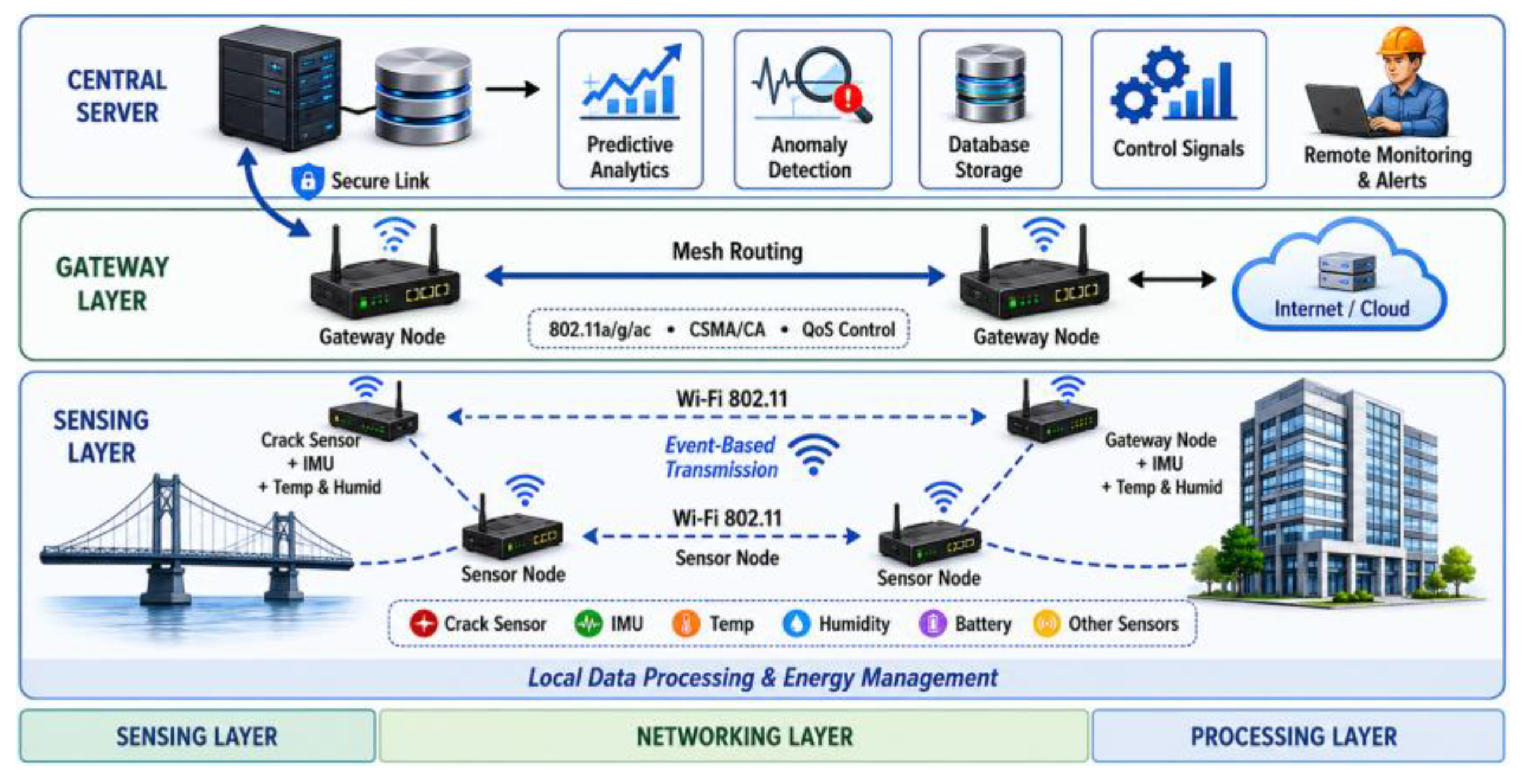
The main difference of the proposed system from traditional wireless sensor networks (WSNs) is the use of Wi-Fi (IEEE 802.11) instead of IEEE 802.15.4-based communication. This approach provides the following advantages:
- higher data transmission throughput;
- ability to transmit large data packets;
- support for the standard IP protocol stack;
- compatibility with existing network infrastructure.
Figure 2 illustrates the general functional diagram of the distributed monitoring system.
R1 – router on the transmitting side;
P1 – radio bridge on the transmitting side;
P2 – radio bridge on the receiving side;
R2 – router on the receiving side;
T/R Server – transceiver server;
DCU – data collection unit;
Wi-Fi – Wi-Fi transceiver operating in client mode;
SU – sensor unit;
MO – monitored object;
EMU – external monitoring interface.
The router on the transmitter side provides network connectivity, enabling the exchange of measurement data in remote or hard-to-access areas of the system via the P1 radio bridge.
The P1 radio bridge transmits the broadband data stream to the P2 receiving radio bridge, which then forwards the data to the R2 router on the receiving side.
The monitored object corresponds to the structure under study, i.e., the building. The sensor unit consists of numerous sensors that measure dynamically changing parameters describing the technical condition of the structure. These include a distance sensor for detecting cracks, temperature and humidity sensors for assessing environmental impact, and an inertial measurement unit (IMU) that includes an accelerometer, gyroscope, and magnetometer to measure spatial orientation and magnetic field.
The sensor node transmits the measured data to a Wi-Fi module operating in client mode (referred to as the “Wi-Fi” module). This module consists of an analog-to-digital converter (ADC), a microcontroller, and an antenna. The ADC converts the sensor’s analog signals (if any) into digital form and sends them to the microcontroller. The microcontroller processes the data according to the embedded algorithm and transmits the processed information to the router via the antenna.
The R1 router sends the received measurement data to the Transceiver Server (T/R Server), where the data is processed according to a specific algorithm. The processed results are then converted into processed data and transmitted through the T/R Server–R–Wi-Fi–Emu–MO sequence or directly through the EMU–MO channel.
Finally, the system performs data analysis to adjust and stabilize the parameters of the controlled process.
To store and process measurement results, the server transmits data via the HTTPS protocol to the data collection unit (DCU), which may include a personal computer, smartphone, laptop, embedded system, or tablet.
A functional diagram (Figure 3) was created to illustrate the data collection and transmission process, which is implemented based on the proposed system architecture.
The following symbols are used in Figure 3:
SS – signal source;
HC-SR04 – ultrasonic distance sensor;
MPU-9250 – inertial measurement unit (IMU) integrating an accelerometer, gyroscope, and magnetometer;
GY-521 – compact module with a 3-axis accelerometer and 3-axis gyroscope, controlled via the I2C protocol;
DHT – temperature and humidity sensor;
ADC – analog-to-digital converter;
MCU – microcontroller unit;
A – antenna;
ESP32 – Wi-Fi module;
ThingSpeak server – cloud server used in the study for data storage and visualization;
Router – network device that forwards data packets between network segments based on routing rules and tables;
Radio Bridge 1 – external access point forming a directional beam for data transmission;
Radio Bridge 2 – network device that receives a signal from a provider or another router and distributes it within a local network;
HTTPS – secure Hypertext Transfer Protocol (default port 443);
PC – personal computer.
The functional diagram of the system and the justification for the selection of its structural components are presented below. Signals corresponding to monitored parameters are generated and recorded by the sensor modules. The power supply is designed to provide a constant power supply to both the sensor modules and the Wi-Fi communication module.
In the experimental study, a total of 500 measurements were taken for each type of sensor used in the system.
The system includes several types of sensors. The distance sensor is used to measure the dynamics of crack propagation. For this purpose, the HC-SR04 ultrasonic distance sensor was chosen. This sensor was selected for its ability to provide precise digital measurements based on the principle of ultrasonic echolocation.
The sensor module emits an ultrasonic pulse and detects the reflected signal from the target object. By measuring the time interval between transmission and reception, the distance to the target object is calculated. Additionally, the HC-SR04 sensor is compatible with a wide range of microcontrollers, which makes it easy to integrate into various control systems.
Four sensors of this type were used in the experimental setup.
The MPU-9250 is a multi-sensor module that integrates an accelerometer, gyroscope, and magnetometer. This study used the MPU-6050 and MPU-9250 sensors. Inertial measurement units use microelectromechanical systems (MEMS) technology, which allows the integration of mechanical sensing elements and electronic circuits onto a single chip.
Each sensor provides measurement along three orthogonal axes (X, Y, and Z). The MPU-6050 offers a 6-degree-of-freedom (6-DoF) configuration by integrating a three-axis accelerometer and a three-axis gyroscope. In contrast, the MPU-9250 extends this functionality to a 9-degree-of-freedom (9-DoF) system, which includes an integrated ak8963 magnetometer that enables magnetic field measurement and functions as a digital compass. This allows for gyroscope drift compensation and determination of the device’s absolute orientation relative to the Earth’s magnetic field.
Both sensors are equipped with an integrated Digital Motion Processor (DMP) capable of sensor fusion and generating orientation results in the form of Quaternions or Euler angles. This significantly reduces the computational load on the main microcontroller.
Communication with the control board is carried out via the I2C protocol, while the MPU-9250 supports a higher-speed SPI interface. Both modules feature an integrated temperature sensor used not only for environmental monitoring but also to compensate for temperature errors in accelerometer and gyroscope measurements, thereby enhancing system stability under varying temperature conditions.
Thus, the MPU-9250 is an advanced solution that combines the functionality of the MPU-6050 (or its updated version, the MPU-6500) with an integrated magnetometer in a magnetometer form factor. The MPU-6050 is commonly used in modules like the GY-521. The GY-521 is a compact MPU-6050-based module that combines a 3-axis accelerometer and a 3-axis gyroscope, controlled via the I2C communication protocol. This is one of the most widely used MPU-6050 chip-based expansion boards, providing convenient interaction with microcontrollers.
In addition to the sensing element, the GY-521 module includes necessary ancillary components such as a voltage regulator (operating from 3.3 V to 5 V), I2C bus pull-up resistors, and an LED power indicator. These features make it a compact and practical solution for integrating inertial sensing capabilities into wireless monitoring systems.
The proposed distributed wireless system uses MPU-6050 (GY-521 module) and MPU-9250 sensors. Several sensor nodes are placed on the monitored structure at predetermined locations defined by its geometric dimensions (height and width). Each sensor node is connected to a separate Control Module with Wi-Fi connectivity.
To increase energy efficiency, the modules are designed to operate in a deep sleep mode along with energy-saving algorithms. Since data transmission is not continuous but periodic, power is supplied to the active components of the system only during measurement sessions.
Sensors installed in various locations record dynamic parameters along three orthogonal axes, which allows for the independent acquisition of data from the accelerometer, gyroscope, and (in the case of the MPU-9250) magnetometer along the X, Y, and Z axes.
The DHT11 temperature and humidity sensor is a digital device with a calibrated output signal, made with patented digital signal acquisition technology that ensures reliable operation and long-term stability. The sensor integrates a resistive element for measuring humidity and a thermistor for measuring temperature, both connected to an on-board 8-bit microcontroller.
The DHT22 is a more accurate alternative, each of which is factory-calibrated in a controlled environment. The calibration coefficients are stored in the controller’s one-time programmable (OTP) memory and are used during data collection to improve measurement accuracy and compensate for systematic errors.
Both sensors, with their small size, low power consumption, and single-wire communication interface, are suitable for a wide range of operating conditions. Their standard pin configuration simplifies integration into control systems.
The DHT11 sensor is suitable for indoor use due to its cost-effectiveness and operating range (0 °C to +50 °C, relative humidity 20% to 80%). However, the DHT22 sensor is better suited for outdoor use or harsh environmental conditions. It provides improved metrological performance, including an approximate 2-5% humidity measurement accuracy across the full 0-100% range, as well as an extended operating temperature range of -40 °C to +80 °C.
The hardware and software compatibility of these sensors ensures their seamless interchangeability within the proposed system, allowing for flexible adaptation to specific technical requirements and environmental conditions without degradation in performance.
Comprehensive analysis allows for the detection of potential communication errors and transmission delays within the system. Ensuring the reliability of measurement results is crucial for accurately assessing the technical condition of structures and for supporting decision-making in remote monitoring applications.
Measured values are transmitted from the main sensor elements to the Wi-Fi module, which must ensure flexibility in network deployment and support scalable distributed system topologies. The ability to simultaneously record data and transmit packets is a key requirement for the communication network.
The ESP32 System on a Chip (SoC), manufactured using 40nm TSMC technology, meets these requirements. It is characterized by low power consumption and supports advanced power dynamic management features. Wi-Fi transmit power control allows for finding the optimal trade-off between range, data rate, and energy efficiency, depending on the operating conditions.
The ESP32 computing core is a dual-core 32-bit xtensa LX6 microprocessor with a clock speed of up to 240 MHz and a performance of up to 600 DMIPS. The platform also includes a wide range of peripherals, including 18 channels of a 12-bit analog-to-digital converter (ADC).
For prototyping and experimental testing, the Arduino IDE is a suitable development environment thanks to its simplicity and extensive library support. However, to implement complex energy-saving strategies and optimize system resources, the ESP-IDF framework is preferable. Its main advantage is the menuconfig utility, which allows for low-level configuration of the system’s parameters, including Boot Options, SDK optimization and adjusting the processor clock speed, which is crucial for reducing power consumption in distributed monitoring nodes.
The measured data from the ESP32-based sensor node is digitized (in the case of analog sensors) and processed by the embedded microcontroller. The firmware manages the core functions, including setting up the Timer, establishing a wireless connection with the receiving party, and transmitting data to the server.
The wireless communication is established through a router that connects the transmitting and receiving network segments via Wi-Fi. A standard Wi-Fi router can be used for this purpose, as it is easy to place in the controlled area, supports multiple antenna configurations, and provides sufficient resistance to interference.
The server is responsible for storing and processing measurement data received from the sensor nodes. To ensure operational reliability and data security, it is generally recommended to use a specially protected server with limited access. However, for the purposes of this study, which includes experimental testing and system verification, the ThingSpeak cloud platform (www.thingspeak.com) was chosen due to its accessibility and suitability for rapid prototyping and visualization of data.
The final stage in the system’s functional diagram involves transmitting the measurement results from the server to the end-user’s device. Since the proposed system is wireless and autonomous, the data exchange is implemented in accordance with the widely accepted OSI reference model.
The connection between the server and the end device is established using the HTTPS protocol, which enhances security compared to the widely used HTTP protocol and guarantees data integrity and confidentiality during transmission.
Based on the processes and operations described above, an algorithm for the distributed control system is developed, as shown in Figure 4. The proposed algorithm describes the operation of a single communication channel in the building monitoring system.
The algorithm is organized into four columns. The left column represents the interaction between the routers and the radio bridges on the transmitting and receiving sides. The second column depicts the data transmission between the receiving radio bridge and the router. The third column describes the operation of the sensor node, including the transmission of collected data and measurement results to the server. The rightmost column represents the reception, processing, and visualization of data on the end-user’s device.
After initializing the sensors and the Wi-Fi module, an IP address is assigned. Then the Wi-Fi module periodically requests measurement data from the sensors. In case of an error, the request is repeated until reliable data is received.
After receiving data from the sensors, the Wi-Fi module establishes a connection with the router. If the connection is successful, the measurement results are sent to the router and then to the remote server. If the connection attempt fails, the process repeats until a stable connection is established.
The router transmits the collected data to the server via Wi-Fi, where it is logged and stored. At this point, the data becomes available to the end user. After each measurement cycle, the system enters a standby mode for a predefined time interval, after which the data collection process is repeated according to the described algorithm.
The end-user’s device initializes operation after establishing a connection with the server. After a successful HTTPS connection, the device retrieves the stored data and converts it into a visualization-compatible format.
Structural condition assessment is based on the analysis of threshold values. If the measured values remain below a given maximum threshold, the structure’s condition is considered normal. If the measured values exceed the threshold and this condition persists in subsequent measurements, the structural condition is classified as critical, requiring intervention by maintenance personnel.
For structures such as bridges and engineering facilities, the collected data is continuously analyzed to detect dynamic changes. This enables informed decision-making and supports early detection of structural degradation and reduces the risk of critical failures.
The proposed algorithm supports periodic asynchronous data acquisition and fault-tolerant wireless transmission between distributed sensing nodes.
5. Network Model
The network layer of the proposed distributed structural monitoring system is responsible for routing, addressing, connecting nodes, and ensuring stable data transmission in a dynamically changing topology.
Unlike traditional centralized SHM systems, which follow a hierarchical data exchange structure, the proposed architecture uses a hybrid mesh/ad hoc model. This approach provides the following key capabilities:
- network self-organization;
- resilience to node failures;
- multi-path data transmission;
- scalability with an increasing number of sensor nodes.
A comparative analysis of existing SHM architectures is presented in Table 1.
Table 2 presents a comparative analysis of the proposed model and classical MANET architectures, highlighting several key advantages of the proposed approach.
The key network components used in this study were selected based on the analysis presented above.
To establish a backbone data transmission network and test the proposed distributed monitoring algorithms under field conditions, the MikroTik RBLHGG-60ad radio transmission system (wireless line-of-sight) was used to create a backbone data transmission network and test the proposed distributed monitoring algorithms under field conditions. This system is designed to establish high-speed point-to-point (PtP) connections between remote nodes.
The selected equipment provides low-latency communication and supports data transfer rates of up to 1 Gbps over distances of up to 1,500 meters. A key feature of this system is that it operates in the unlicensed 60 GHz frequency band, which largely eliminates the interference typical of the 2.4 GHz and 5 GHz bands, thereby ensuring a high signal-to-noise ratio (SNR).
From a radiophysical perspective, operation in the V-band (60 GHz) is subject to oxygen (O2) absorption, which naturally limits the signal’s propagation range. This effect reduces interference in neighboring networks and enhances communication security.
A directional antenna with a narrow beam pattern allows for beamforming, concentrating signal energy, and improving transmission efficiency. This is particularly important for heterogeneous monitoring data streams, including telemetry, high-definition video, and vibration monitoring data.
Integrating the RBLHGG-60ad into the experimental setup allows for the integration of geographically distributed Wi-Fi nodes into a unified communication infrastructure, ensuring continuous bidirectional data exchange between sensor nodes and the central server.
In addition, the use of high-speed radio links reduces latency and minimizes transmission distortion, which is critical for data synchronization when monitoring dynamic loads in complex engineering structures.
Thus, the selected hardware solution enables the implementation of a reliable, interference-resistant, and resistant to environmental conditions data transmission architecture capable of maintaining the integrity of real-time data streams.
The optimal solution for integrating 60 GHz backbone radio transmitters into a unified distributed monitoring infrastructure is the MikroTik hAP ax3 router, which functions as an intelligent aggregation gateway.
This model was selected due to its support for the Wi-Fi 6 (IEEE 802.11 ax) standard, including Orthogonal Frequency Division Multiple Access (OFDMA), which enables efficient handling of multiple distributed ESP32-based nodes with reduced latency and minimal channel interference.
The device’s computing core is based on a high-performance quad-core ARM Cortex-A53 processor with a clock speed of up to 1.8 GHz. This provides sufficient processing power for traffic prioritization and ensures stable processing of high-throughput data streams received from RBLHGG-60ad radio transmissions.
The presence of a 2.5-gigabit Ethernet port enables the continuous transmission of aggregated telemetry and high-definition video streams to a local processing server without bandwidth bottlenecks.
Within the edge-computing framework, the router’s operating system supports local data filtering, load balancing among sensor groups, and automatic channel redundancy. Furthermore, hardware support for IPsec encryption ensures a high level of data transmission security when communicating over external networks.
Thus, the combination of the hAP ax3 router and the 60 GHz radio transmitter creates a robust network infrastructure capable of maintaining high measurement reliability and operational stability in a distributed monitoring system under varying traffic loads and environmental conditions.
6. Materials and Methods
The processing layer serves as the computational and analytical core of the distributed monitoring system and is responsible for:
- -
- aggregating data from sensor nodes;
- -
- pre-filtering and normalizing measurements;
- -
- extracting diagnostic features;
- -
- detecting anomalies and structural damages;
- -
- generating diagnostic and maintenance notifications.
In contrast to classical centralized SHM systems, where data processing is conducted solely on a central server, the proposed architecture implements a hierarchical distributed processing model. This approach reduces network traffic load and enhances the system’s fault tolerance.
The measurement data acquired by sensor nodes based on ESP32-based sensor nodes is digitized (in the case of analog sensors) and processed by an onboard microcontroller. The firmware manages essential operations, such as timer configuration, wireless connection management, and data transmission to the server.
The server is responsible for the storage and processing of measurement data collected from sensor nodes. For deployment in real-world scenarios, a specialized secure server with restricted access is proposed to ensure data integrity and system reliability. However, for the purposes of this research, the ThingSpeak cloud platform was utilized to support experimental validation, system testing, and structural condition monitoring.
7. Materials and Methods
Based on the proposed algorithm and functional diagram, a series of experiments were conducted. The experimental study included not only the measurement of the main sensor parameters but also an assessment of the reliability of data transmission over the wireless communication channel, including assessment of transmission reliability and communication stability.
Following the experiments, all collected data were subjected to statistical analysis using statistical data processing methods to identify measurement uncertainties and communication-related errors.
The obtained results are presented in Figure 5, Figure 6, Figure 7, Figure 8, Figure 9, Figure 10, Figure 11 and Figure 12, illustrating the system’s performance under various operating conditions.
A series of 500 consecutive measurements were performed using the developed algorithm and the functional architecture of the distributed monitoring system. The dataset included readings from distance sensors, magnetometer channels, as well as temperature and humidity sensors.
In the course of an experimental study, a comparative evaluation of the performance of wired and wireless data transmission methods was conducted. This approach allowed for a comprehensive assessment of the stability of both measurement nodes and the wireless communication channel under conditions of telemetry data transmission.
The collected data were processed using statistical analysis methods and time series visualization. This enabled the identification of trends in the measured parameters, assessment of the correspondence between the two recording methods, and quantitative evaluation of potential deviations.
No missing values were detected in any of the analyzed time series, which indicates the reliability of data acquisition and the integrity of the measurement process throughout the entire experimental cycle.
As shown in Figure 5, both distance sensors exhibit a consistent temporal pattern in the wireless transmission channel across the entire observation interval.
For distance sensor No. 1, the Mean Absolute Error (MAE) between wired and wireless measurements was approximately 0.043 mm, and the Root Mean Square Error (RMSE) was approximately 0.045 mm. The corresponding values for distance sensor No. 2 were 0.047 mm and 0.049 mm, respectively.
The complete dataset of 500 measurements revealed no sudden deviations or anomalies in the wireless signal. The waveform characteristics and local fluctuations remained within a stable range throughout the observation period.
These results indicate that the wireless transmission channel reliably supports the dynamic behavior of distance changes, which is crucial for applications such as crack tracking and detecting small-scale geometric variations in structural elements.
The results presented in Figure 6 show that the absolute error of wireless transmission for both distance sensors remains consistently low across the entire dataset of 500 measurements and does not accumulate over time.
The Mean Absolute Error (MAE) for distance sensor No. 1 was approximately 0.043 mm, with a maximum deviation not exceeding 0.057 mm. The corresponding values for distance sensor No. 2 were 0.047 mm and 0.062 mm, respectively.
In both cases, the error profiles remain constant, characterized by localized fluctuations that do not translate into long-term drift or an increase in systematic errors as the number of measurements increases.
These observations confirm the stability of the wireless data transmission channel for distance measurements and indicate its suitability for long-term structural monitoring applications.
As shown in Figure 7, the wireless data transmission method generally reproduces the temporal patterns of magnetometric signals across all three coordinate axes, confirming the feasibility of the system designed for observing spatially oriented objects.
The highest agreement between wired and wireless measurements is observed along the Y-axis, where the Mean Absolute Error (MAE) is approximately 0.497 µT and the Root Mean Square Error (RMSE) is approximately 0.639 µT. For the X-axis, the MAE and RMSE values are approximately 0.592 µT and 0.769 µT, respectively, while for the Z-axis, they are 0.556 µT and 0.680 µT, respectively.
In all cases, the wireless channel preserves the overall waveform and the main regions of signal increase and decrease. However, local fluctuations are observed at certain intervals, which are higher compared to the amplitude recorded in the distance measurement channels.
These results indicate that, despite minor deviations, the wireless transmission method maintains sufficient accuracy for capturing the magnetometric signal dynamics in structural monitoring applications.
The comparison of the absolute error distributions shown in Figure 8 indicates that the most stable agreement between magnetometer channels is observed along the Y-axis, while the X-axis exhibits the greatest variability in deviations. The Z-axis shows intermediate behavior between these two states.
The maximum recorded deviations were approximately 2.330 µT along the X-axis, 2.165 µT along the Y-axis, and 1.734 µT along the Z-axis.
Although the general signal patterns are preserved, the magnetometer channels demonstrate higher sensitivity to transmission-induced fluctuations compared to the distance sensors. This effect should be considered when interpreting spatial measurements, especially in applications requiring high precision.
The DHT11 sensor results show varying levels of agreement between wired and wireless data acquisition methods for temperature and humidity measurements, as illustrated in Figure 9.
The Mean Absolute Error (MAE) for the temperature channel was approximately 0.842 °C, and the Root Mean Squared Error (RMSE) was approximately 0.867 °C. The wireless data sets retain the overall temperature trend; however, a systematic bias towards lower values is observed.
For the humidity channel, the MAE and RMSE were approximately 1.620% and 1.763% respectively. The maximum deviation reached around 5.9%, indicating high variability compared to the temperature measurement.
Overall, the DHT11 sensor exhibits consistent trend reproduction; however, the level of agreement between wired and wireless measurements is lower than that observed for the distance and magnetometer channels.
As shown in Figure 10, the DHT22 temperature channel exhibits a high degree of agreement between wired and wireless data transmission methods.
The Mean Absolute Error (MAE) for temperature measurement was approximately 0.048 °C, and the Root Mean Square Error (RMSE) was approximately 0.104 °C, representing one of the best results among all analyzed channels.
For the humidity channel, the MAE was approximately 1.191%, and the RMSE was 2.104%, which may be attributed to the presence of individual measurements with relatively large fluctuations. The observed maximum deviation was around 5.8%, indicating an increased variability in humidity readings.
Overall, the DHT22 sensor demonstrates high accuracy and stability in temperature measurement, while the humidity data shows greater variability, likely due to sensor sensitivity and environmental influences.
As shown in Figure 11, the integrated comparison of absolute errors across all measurement channels reveals the overall error distribution pattern and identifies the most stable sensor groups.
It should be noted that the analyzed channels correspond to different physical quantities and are expressed in different units. Therefore, the proposed comparison is primarily qualitative, focusing not on a direct metrological ranking but on distribution patterns and the relative stability of the channels.
Minimal deviations are observed for the distance sensors and the DHT22 temperature channel. The best performance is achieved by distance sensor No. 1 with a Mean Absolute Error (MAE) of approximately 0.043 mm, while for distance sensor No. 2, this value is 0.047 mm. Among the remaining channels, the DHT22 temperature sensor exhibits the highest stability, with an MAE of 0.048 °C.
The magnetometer axes demonstrate intermediate behavior, with the lowest error recorded along the Y-axis and the highest along the X-axis.
The largest fluctuations are observed in the humidity channels of the DHT11 and DHT22 sensors, as well as in the DHT11 temperature channel, indicating an increased sensitivity of these measurements to discrepancies between wired and wireless data acquisition methods.
The resulting metrics, as depicted in Figure 12, facilitate a quantitative comparison of error characteristics across all measurement channels, based on Mean Absolute Error (MAE) and Root Mean Square Error (RMSE).
It must be emphasized that the indicated values are expressed in units specific to each channel. Therefore, the comparison is intended primarily for a qualitative evaluation of data transmission stability within each measurement group, rather than for a direct inter-channel metrological assessment.
The distance sensors demonstrate the lowest MAE and RMSE values, which corroborates the high stability of transmission during the measurement of small linear displacements. The DHT22 temperature channel also exhibits high stability, considerably outperforming the DHT11 temperature channel by both indicators.
Magnetometric measurements show an average level of error, which is still sufficient to maintain the signal shape and spatial dynamics. In contrast, the humidity channels are characterized by the highest RMSE values, indicating increased variance in individual measurements and requiring careful interpretation of the results for this group of parameters.
Overall, the experimental results demonstrate that the proposed Wi-Fi-based distributed monitoring system provides stable data transmission across all analyzed channels and reliably preserves the temporal dynamics of the measured parameters without compromising the integrity of the time series. The highest correspondence between wired and wireless measurements is observed for the distance sensors and the DHT22 temperature channel, while the greatest variability is associated with the humidity measurements and the selected magnetometric channels.
These findings confirm the practical viability of the proposed architecture and validate that it can be used for remote monitoring of the structural health of building structures.
8. Discussion of Results
The experimental results demonstrate that the developed Wi-Fi-based distributed monitoring system ensures stable transmission of measurement information and preserves the informativeness of signals across all studied channels. One of the key findings is the absence of gaps and structural signal distortions in time series during wireless transmission across all 500 measurement sequences.
This confirms that the proposed architecture operates reliably not only at the level of individual sensor nodes but also throughout the entire data transmission chain, including the sensor, microcontroller, Wi-Fi channel, server, and end-user device. Such performance is crucial for structural health monitoring applications, where the core value lies in the continuous and consistent tracking of parameter changes over time, as opposed to isolated measurements.
The highest level of agreement between wired and wireless data acquisition methods was achieved for distance sensors. The mean absolute error across all measurement groups remained minimal, and the error distribution did not exhibit systematic drift or accumulation over time. These findings indicate that wireless transmission does not distort signal structure or degrade data quality during long-term monitoring.
From a practical standpoint, this is particularly important because distance sensors are widely used for monitoring crack propagation, local deformations, and other small geometric changes that are crucial for assessing the structural health of civil engineering structures.
Magnetometer channels show satisfactory agreement between wired and wireless measurements; however, compared to distance sensors, they exhibit higher levels of error and variability. Nevertheless, the wireless transmission channel preserves the overall structure of the time series across three axes, enabling reliable tracking of spatially oriented parameters over time.
The increased dispersion observed in magnetometer data can be attributed to several factors, including sensitivity to local electromagnetic disturbances, dependence on sensor orientation, and the need for precise calibration in triaxial measurements. Consequently, the magnetometer module should primarily be considered a tool for capturing trends, spatial variations, and anomalous events, while high-precision absolute measurements may require additional filtering and calibration procedures.
Significant differences are noticeable between the temperature and humidity channels of the DHT11 and DHT22 sensors. The DHT22 temperature channel exhibits the highest stability within this group, characterized by low error values and strong agreement between wired and wireless measurements. This confirms that high-accuracy sensors can be effectively integrated into distributed systems without significant degradation of data quality during wireless transmission.
In contrast, the DHT11 temperature channel shows considerable systematic fluctuations, while the humidity channels of both DHT11 and DHT22 sensors display the greatest variability among all measured parameters. This behavior is expected because humidity measurements are sensitive to local microclimate fluctuations, sensor response time, and environmental conditions. Furthermore, humidity readings are influenced by timing discrepancies and the calibration characteristics of low-cost digital sensors, leading to increased inter-channel variability while maintaining an overall trend.
An integrated comparison of all measurement channels reveals that the proposed system does not provide uniform accuracy across all sensor types; however, it reliably preserves diagnostically relevant information for all major parameter groups. From an engineering perspective, this outcome is more significant than achieving stringent quantitative precision because, in real-world structural health monitoring systems, different sensors exhibit varying metrological stability, sensitivity, and dependence on external factors. Consequently, the observed inter-channel differences should be interpreted not as a limitation of the system architecture but as an expression of sensor-inherent characteristics and their interaction with the environment and usage conditions.
The stability of the time series and the absence of data gaps further confirm the reliability of the selected data transmission scheme, including the Wi-Fi communication channel and server infrastructure. These results demonstrate that, with the appropriate configuration of sensor nodes, sampling strategies, and communication parameters, standard Wi-Fi technology can serve not only as a consumer communication technology but also as a practical basis for distributed engineering monitoring systems.
This finding is consistent with the study’s core concept, which states that improved flexibility, scalability, and ease of deployment can be achieved not through specialized proprietary solutions, but through the effective use of widely available network technologies in combination with a properly designed communication algorithm for communication between distributed nodes.
The study also identifies several limitations. First, certain channels, particularly magnetometric and humidity measurements, exhibit significant fluctuations, indicating the need for additional calibration methods, digital filtering, and error compensation. Second, the current system configuration relies on data transmission to an external server platform. While this approach is suitable for experimental validation, practical deployment requires a secure and autonomous infrastructure for data storage and processing. Third, comprehensive validation of a system for long-term structural monitoring requires extensive field experiments under specific operating conditions, including various environmental factors and loading scenarios.
Despite these limitations, the results demonstrate that the proposed Wi-Fi-based distributed monitoring system offers a reliable and accessible solution for recording key structural parameters. Maximum reliability is achieved with the distance sensors and the DHT22 temperature channel, while magnetometric and humidity measurements require further refinement and algorithmic improvements.
Overall, the developed architecture can be viewed as a promising foundation for scalable remote monitoring systems combining wireless data transmission with acceptable measurement accuracy and flexible integration of heterogeneous sensor types.
9. Conclusion
The developed functional architecture of the structural monitoring system was designed considering multiple factors that can affect system performance, including environmental conditions, temporal fluctuations, and signal propagation characteristics. The proposed architecture was validated experimentally through laboratory and field studies. The obtained results confirm the feasibility and practical application of the system in representative operating conditions.
A new operational algorithm for the monitoring system was developed. The algorithm defines a sequence of system operations, including error handling procedures, which ensures reliable system operation under varying monitoring conditions.
A series of experiments were conducted to statistically analyze the collected data and identify possible sources of errors. The measurement results were stored on the server and processed using statistical methods, reflecting the quantitative indicators of transmission stability and measurement reliability.
The proposed structural diagrams and operational algorithm, combined with experimental verification, confirm the scalability of the system for scalable deployment in other application domains. System adaptation can be achieved by modifying the sensor layer and modifying the software framework and sensor interfaces, enabling more efficient deployment in areas such as meteorology, agriculture, and energy systems.
The experimental evaluation demonstrated low transmission-induced deviations for distance sensors and the DHT22 temperature channel, confirming the suitability of Wi-Fi communication for distributed SHM applications.
The scientific contribution of this work lies in the development and validation of a Wi-Fi-based distributed SHM architecture integrating heterogeneous sensors within a unified monitoring framework.
Future research will focus on large-scale field deployment, synchronization optimization, and evaluation of communication quality metrics under varying network conditions.
Author Contributions
Conceptualization, U.Y. and N.K.; methodology, U.Y., N.K., and R.M.; software, U.Y. and R.M.; validation, U.Y., N.K., R.M., and E.N.; formal analysis, U.Y. and N.K.; investigation, U.Y., N.K., and R.M.; resources, M.G. and G.M.; data curation, U.Y. and Z.Z.; writing—original draft preparation, U.Y.; writing—review and editing, N.K., E.N., M.G., G.M., and Z.Z.; visualization, U.Y. and R.M.; supervision, M.G. and N.K.; project administration, N.K.; funding acquisition, M.G. All authors have read and agreed to the published version of the manuscript.
Funding
This research was funded by the Science Committee of the Ministry of Science and Higher Education of the Republic of Kazakhstan under Grant No. AP26197145, “Development of a Distributed Autonomous Wireless Wi-Fi System for Monitoring the Technical Condition of Bridge Structures and Buildings” (2025–2027).
Institutional Review Board Statement
Not applicable.
Informed Consent Statement
Not applicable.
Data Availability Statement
The data presented in this study are available on request from the corresponding author.
Conflicts of Interest
The authors declare no conflicts of interest.
References
- Worden, K.; Farrar, C.R.; Manson, G.; Park, G. The Fundamental Axioms of Structural Health Monitoring. Proc. R. Soc. A 2007, 463, 1639–1664. [Google Scholar] [CrossRef]
- Fan, W.; Qiao, P. Vibration-Based Damage Identification Methods: A Review and Comparative Study. Struct. Health Monit. 2011, 10, 83–111. [Google Scholar] [CrossRef]
- Farrar, C.R.; Worden, K. An Introduction to Structural Health Monitoring. Philos. Trans. R. Soc. A 2007, 365, 303–315. [Google Scholar] [CrossRef] [PubMed]
- Farrar, C.R.; Worden, K. Structural Health Monitoring: A Machine Learning Perspective; Wiley: Chichester, UK, 2012. [Google Scholar] [CrossRef]
- Balageas, D.; Fritzen, C.-P.; Güemes, A. Structural Health Monitoring. In ISTE Ltd.; John Wiley & Sons; London, UK, 2006. [Google Scholar] [CrossRef]
- Lynch, J.P.; Loh, K.J. A Summary Review of Wireless Sensors and Sensor Networks for Structural Health Monitoring. Shock Vib. Dig. 2006, 38, 91–130. [Google Scholar] [CrossRef]
- Noel, A.B.; Abdaoui, A.; Elfouly, T.; Ahmed, M.H.; Badawy, A.; Shehata, M.S. Structural Health Monitoring Using Wireless Sensor Networks: A Comprehensive Survey. IEEE Commun. Surv. Tutor. 2017, 19, 1403–1423. [Google Scholar] [CrossRef]
- Deng, Z.; Huang, M.; Wan, N.; Zhang, J. The Current Development of Structural Health Monitoring for Bridges: A Review. Buildings 2023, 13, 1360. [Google Scholar] [CrossRef]
- Hernandez, S.M.; Bulut, E. WiFi Sensing on the Edge: Signal Processing Techniques and Challenges for Real-World Systems. IEEE Commun. Surv. Tutor. 2023, 25, 1–35. [Google Scholar] [CrossRef]
- Armenta-García, J.A.; González-Navarro, F.F.; Caro-Gutiérrez, J. Wireless Sensing Applications with Wi-Fi Channel State Information: Preprocessing Techniques and Detection Algorithms—A Survey. Comput. Commun. 2024, 224, 254–274. [Google Scholar] [CrossRef]
- Ma, Y.; Zhou, G.; Wang, S. WiFi Sensing with Channel State Information: A Survey. ACM Comput. Surv. 2019, 52, 1–36. [Google Scholar] [CrossRef]
- Nilnoree, S.; Taparugssanagorn, A.; Kaemarungsi, K.; Mizutani, T. Enhancing Wireless Sensor Network in Structural Health Monitoring through TCP/IP Socket Programming-Based Mimic Broadcasting: Experimental Validation. Appl. Sci. 2024, 14, 3494. [Google Scholar] [CrossRef]
- Abruzzese, D.; Micheletti, A.; Tiero, A.; Cosentino, M.; Forconi, D.; Grizzi, G.; Scarano, G.; Vuth, S.; Abiuso, P. IoT Sensors for Modern Structural Health Monitoring: A New Frontier. Procedia Struct. Integr. 2020, 25, 378–385. [Google Scholar] [CrossRef]
- Ryabov, G.G.; Nychik, T.Y.; Smirnov, R.S.; Yakovlev, S.S.; Ushakevich, A.N. Device for Monitoring the Technical Condition of Building Structures. 2019. [Google Scholar]
- Volokhov, E.M.; Kozhukharova, V.K.; Sushko, E.T. Method for Monitoring Crack Parameters in Building Structures Using Non-Metric Camera Images. Russian Patent RU2832428C1, 24 December 2024. [Google Scholar]
- Marques, G.; Saini, J.; Dutta, M.; Singh, P.K.; Hong, W.-C. Indoor Air Quality Monitoring Systems for Enhanced Living Environments: A Review toward Sustainable Smart Cities. Sustainability 2020, 12, 4024. [Google Scholar] [CrossRef]
- Salamone, F.; Belussi, L.; Danza, L.; Galanos, T.; Ghellere, M.; Meroni, I. Design and Development of a Nearable Wireless System to Control Indoor Air Quality and Indoor Lighting Quality. Sensors 2017, 17, 1021. [Google Scholar] [CrossRef]
- He, J. Remote Monitoring and Intelligent Failure Diagnosis of Rotating Machinery Using the B/S Mode. Int. J. Mechatron. Appl. Mech. 2021, 10, 181–189. [Google Scholar] [CrossRef]
- Mardanshahi, A.; et al. Sensing Techniques for Structural Health Monitoring. Sensors 2025, 25, 1424. [Google Scholar] [CrossRef] [PubMed]
- Ramalingamorcid, S.P.; Shanmugam, P.K. A Comprehensive Review on Wired and Wireless Communication Technologies and Challenges in Smart Residential Buildings. Recent Adv. Comput. Sci. Commun. 2022, 15, 1140–1147. [Google Scholar] [CrossRef]
- Badenhop, C.W.; Graham, S.R.; Ramsey, B.W.; Mullins, B.E.; Mailloux, L.O. The Z-Wave Routing Protocol and Its Security Implications. Comput. Secur. 2017, 68, 112–129. [Google Scholar] [CrossRef]
- Tosi, J.; Taffoni, F.; Santacatterina, M.; Sannino, R.; Formica, D. Performance Evaluation of Bluetooth Low Energy: A Systematic Review. Sensors 2017, 17, 2898. [Google Scholar] [CrossRef]
- Kim, H.-S.; Kumar, S.; Culler, D. Thread/OpenThread: A Compromise in Low-Power Wireless Multihop Network Architecture for the Internet of Things. IEEE Commun. Mag. 2019, 57, 158–163. [Google Scholar] [CrossRef]
- Alobaidy, H.A.H.; Nordin, R.; Abdullah, N.F. A Review on ZigBee Based WSNs: Concepts, Infrastructure, Applications, and Challenges. Int. J. Electr. Electron. Eng. Telecommun. 2020, 9, 189–198. [Google Scholar] [CrossRef]
- Zhang, C.; Patras, P.; Haddadi, H. Deep Learning in Mobile and Wireless Networking: A Survey. IEEE Commun. Surv. Tutor. 2019, 21, 2224–2287. [Google Scholar] [CrossRef]
- Omar, H.; Abboud, K.; Cheng, N.; Malekshan, K. A Survey on High Efficiency Wireless Local Area Networks: Next Generation WiFi. IEEE Commun. Surv. Tutor. 2016, 18, 2315–2344. [Google Scholar] [CrossRef]
- Pahlavan, K.; Krishnamurthy, P. Evolution and Impact of Wi-Fi Technology and Applications: A Historical Perspective. J. Telecommun. Inf. Technol. 2021, 4, 3–17. [Google Scholar] [CrossRef]
- López-Higuera, J.M.; Cobo, L.R.; Incera, A.Q.; Cobo, A. Fiber Optic Sensors in Structural Health Monitoring. J. Light. Technol. 2011, 29, 587–608. [Google Scholar] [CrossRef]
- Abdulkarem, M.; Samsudin, K.; Rokhani, F.Z.; Rasid, M.F.A. Wireless Sensor Network for Structural Health Monitoring: A Contemporary Review of Technologies, Challenges, and Future Direction. Struct. Health Monit. 2020, 19, 693–735. [Google Scholar] [CrossRef]
- Hou, L.; Zhao, S.; Xiong, X.; Zheng, K.; Chatzimisios, P.; Hossain, M.S.; Xiang, W. Internet of Things Cloud: Architecture and Implementation. IEEE Commun. Mag. 2016, 54, 32–39. [Google Scholar] [CrossRef]
- Soomro, M.A.; Channa, M.I.; Hussain, Z.; Ahmed, M. EPLAODV: Energy Priority and Link Aware Ad-hoc On-demand Distance Vector Routing Protocol for Post-disaster Communication Networks. Eng. Technol. Appl. Sci. Res. 2020, 10, 5148–5152. [Google Scholar] [CrossRef]
- Barry, R.; van Glabbeek, R.; Höfner, P. Formalising the Optimised Link State Routing Protocol. Electron. Proc. Theor. Comput. Sci. 2020, 316, 40–71. [Google Scholar] [CrossRef]
- Zarzoor, A.R. Enhancing Dynamic Source Routing (DSR) Protocol Performance Based on Link Quality Metrics. In Proceedings of the 2021 International Seminar on Application for Technology of Information and Communication (iSemantic), Semarang, Indonesia, 18–19 September 2021; pp. 17–21. [Google Scholar] [CrossRef]
Figure 2.
Structural diagram of the distributed monitoring system.
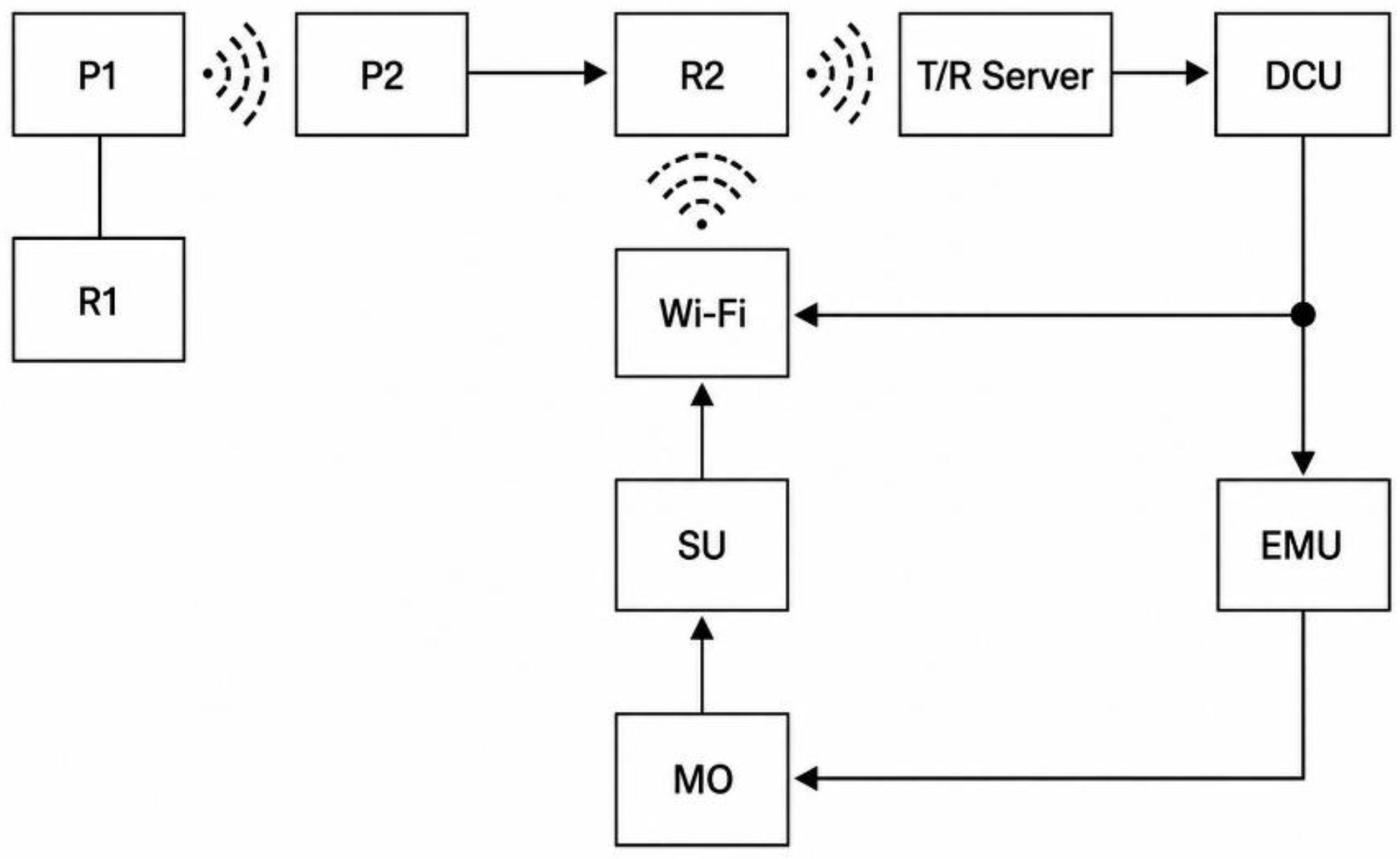
Figure 3.
Functional diagram of a distributed monitoring system.
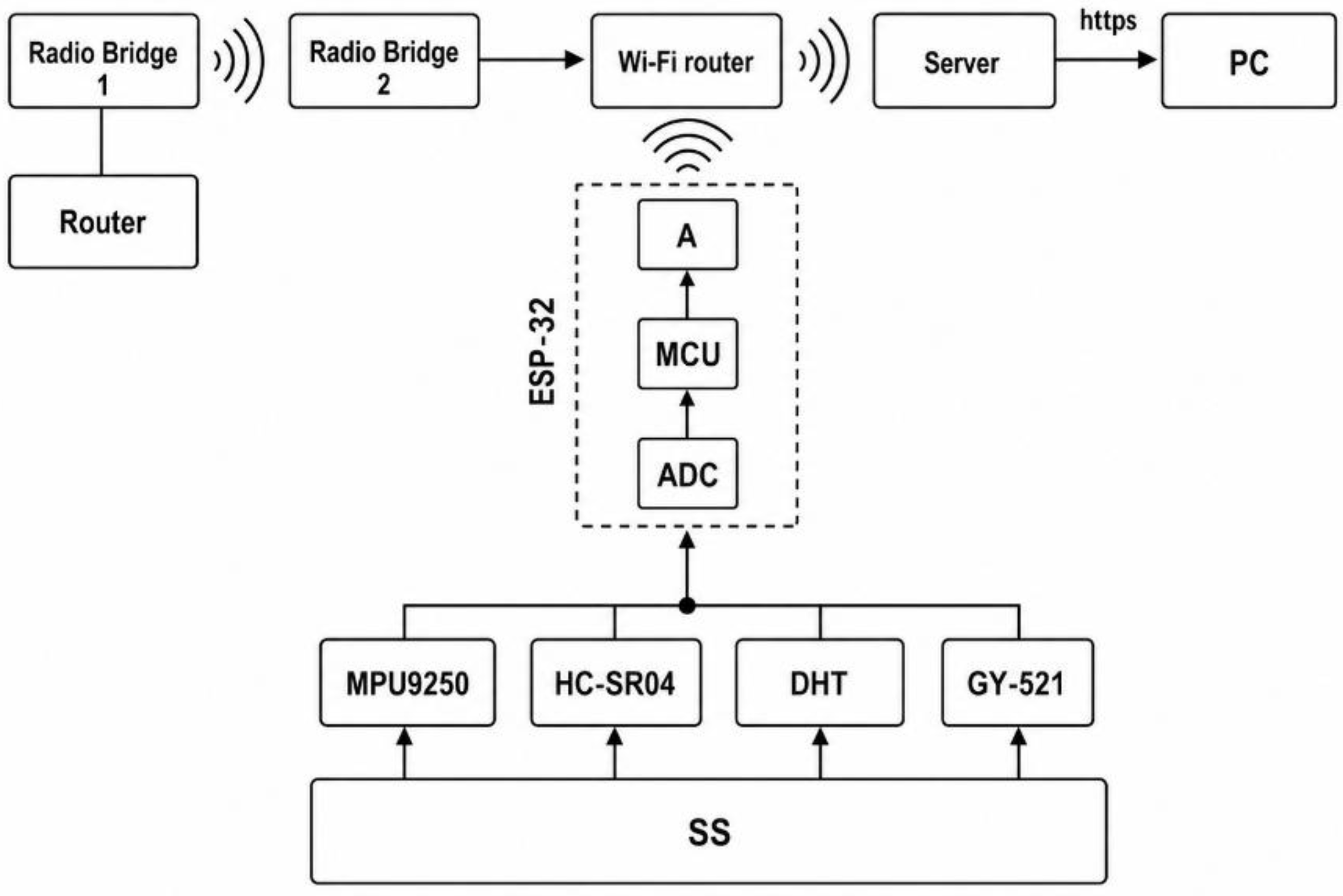
Figure 4.
Algorithm of a distributed monitoring system.
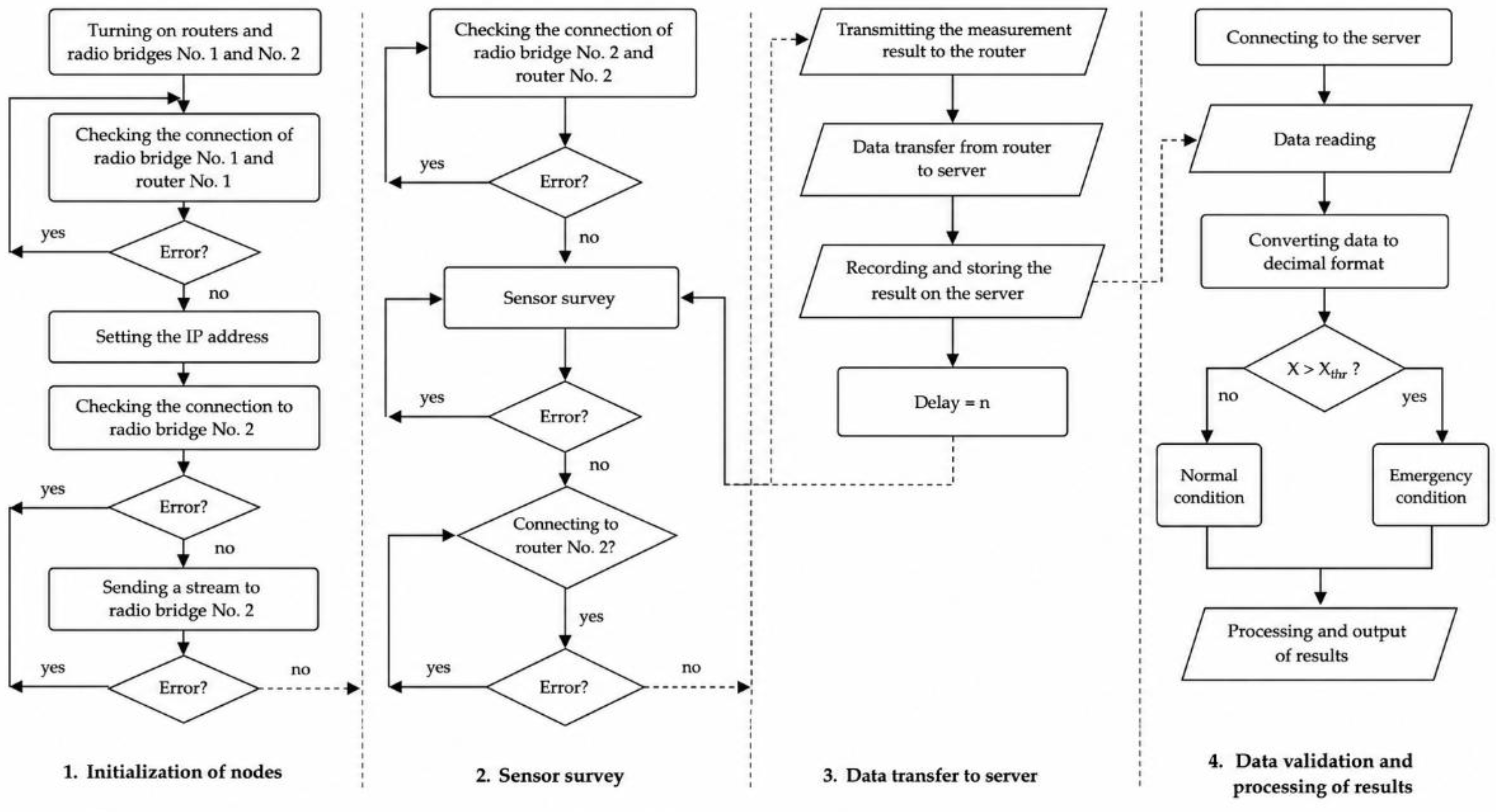
Figure 5.
Comparison of measurement results of distance sensors for wired and wireless data transmission: (a) distance sensor No. 1; (b) distance sensor No. 2.
Figure 5.
Comparison of measurement results of distance sensors for wired and wireless data transmission: (a) distance sensor No. 1; (b) distance sensor No. 2.
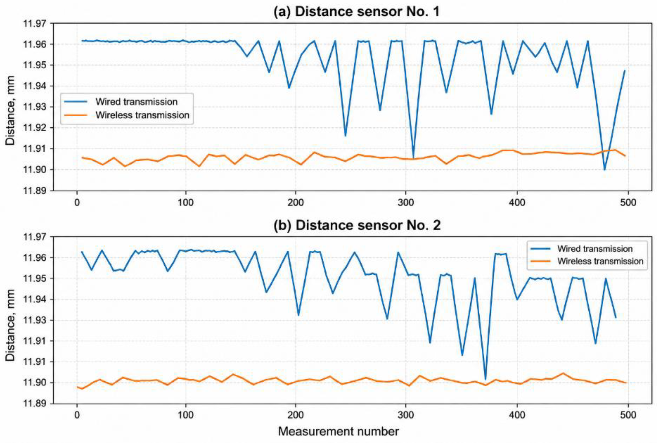
Figure 6.
The absolute measurement error of distance sensors in wireless data transmission relative to the wired method is: (a) distance sensor No. 1; (b) distance sensor No. 2.
Figure 6.
The absolute measurement error of distance sensors in wireless data transmission relative to the wired method is: (a) distance sensor No. 1; (b) distance sensor No. 2.
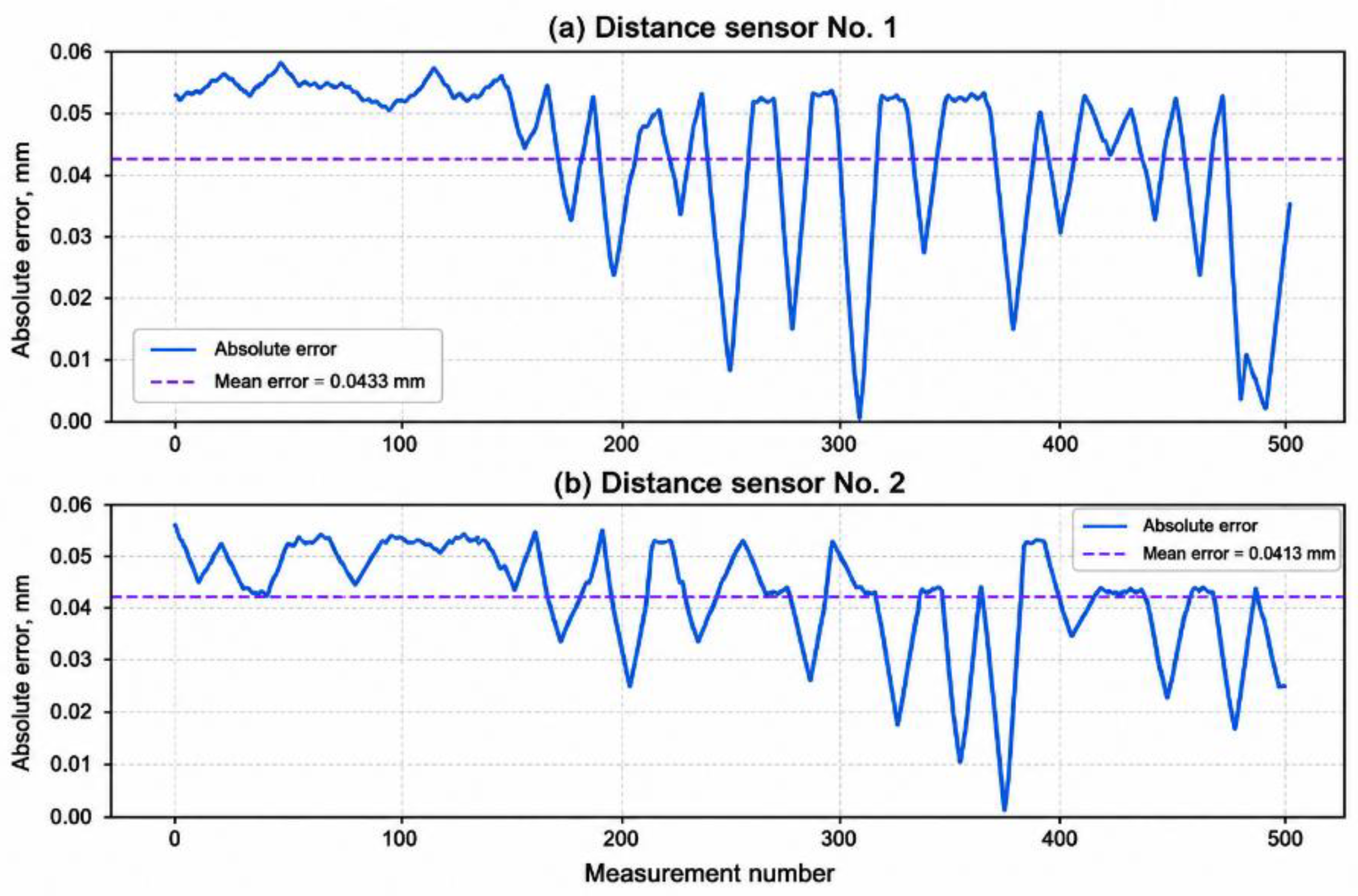
Figure 7.
Comparison of magnetometer measurement results on three axes for wired and wireless data transmission: (A) X axis; (b) Y axis; (c) Z axis.
Figure 7.
Comparison of magnetometer measurement results on three axes for wired and wireless data transmission: (A) X axis; (b) Y axis; (c) Z axis.
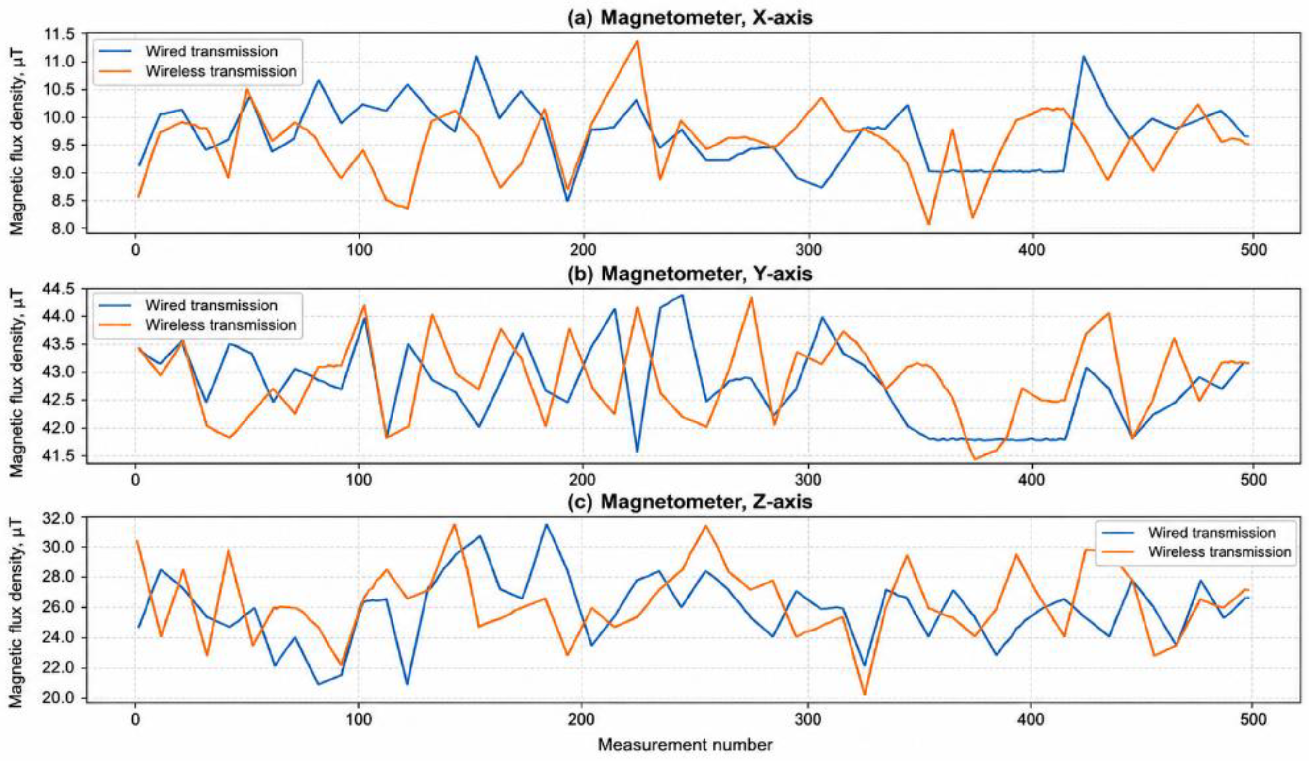
Figure 8.
Distribution of absolute error for magnetometer channels along the X, Y, and Z axes (outliers are not shown for clarity).
Figure 8.
Distribution of absolute error for magnetometer channels along the X, Y, and Z axes (outliers are not shown for clarity).
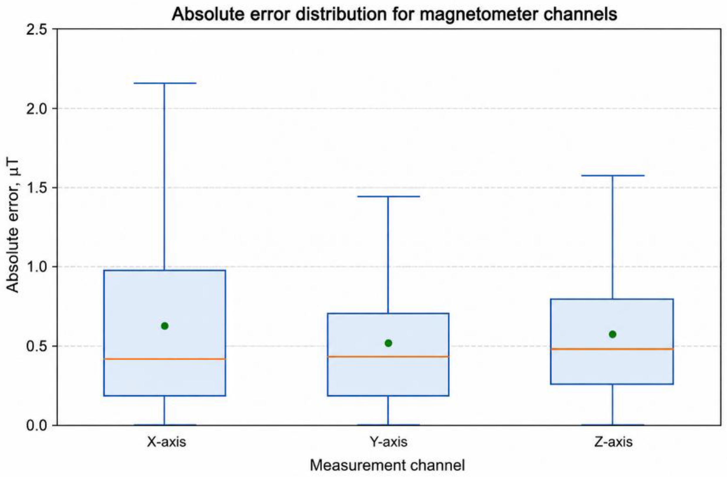
Figure 9.
Comparison of the temperature and humidity measurement results of the DHT11 sensor with Wired and wireless data transmission: (a) temperature; (b) humidity.
Figure 9.
Comparison of the temperature and humidity measurement results of the DHT11 sensor with Wired and wireless data transmission: (a) temperature; (b) humidity.
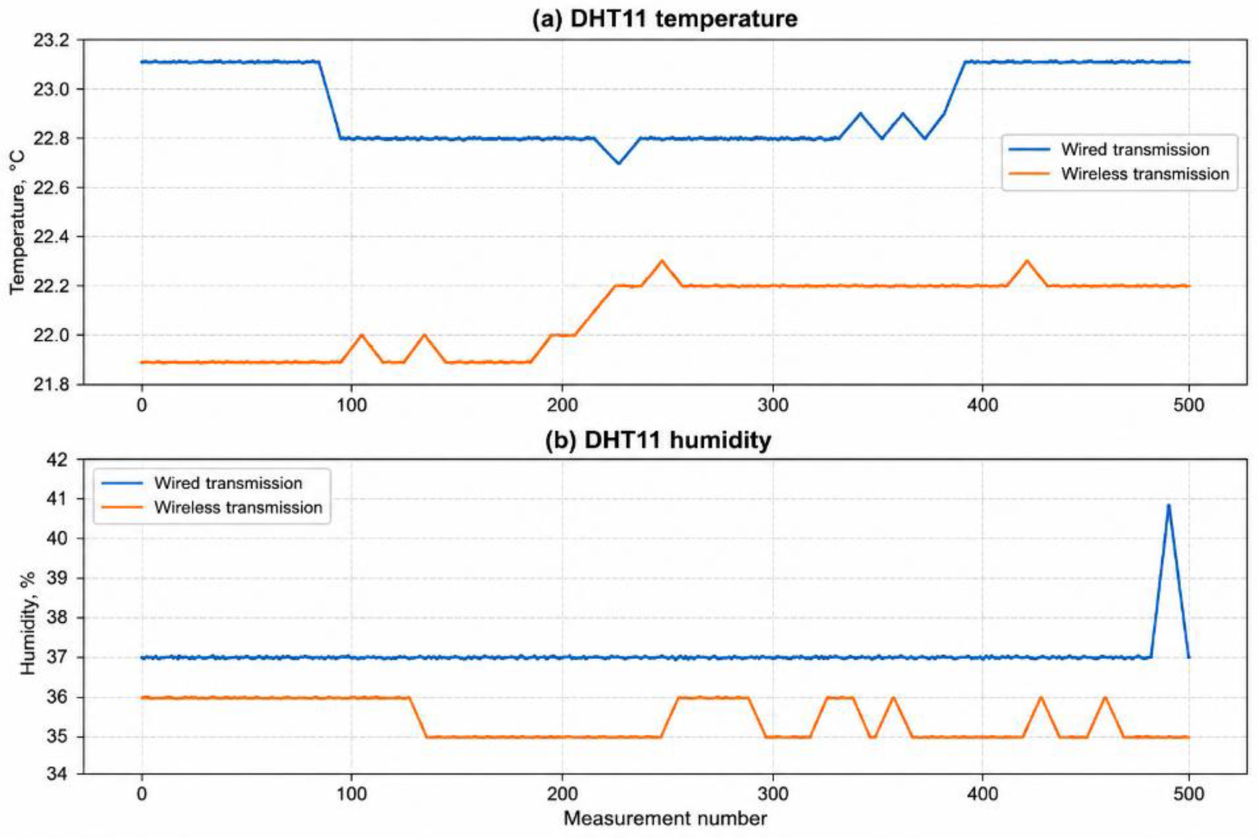
Figure 10.
Comparison of the temperature and humidity measurement results of the DHT11 sensor with Wired and wireless data transmission: (a) temperature; (b) humidity.
Figure 10.
Comparison of the temperature and humidity measurement results of the DHT11 sensor with Wired and wireless data transmission: (a) temperature; (b) humidity.
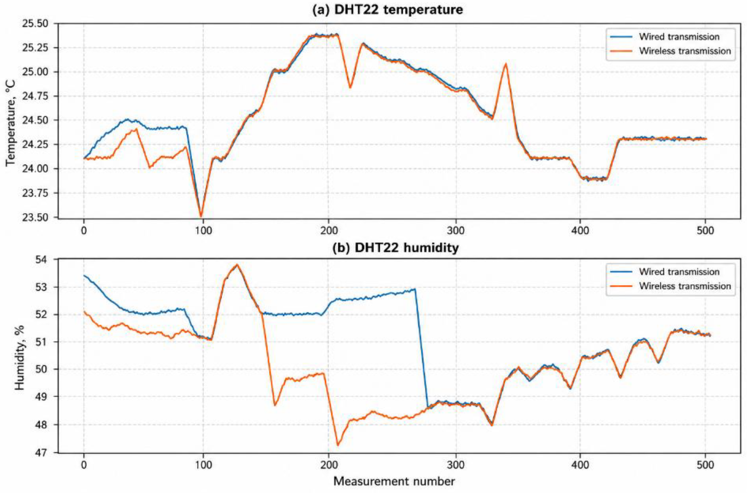
Figure 11.
Distribution of absolute error across all measurement channels of the developed monitoring system (outliers are not shown for clarity).
Figure 11.
Distribution of absolute error across all measurement channels of the developed monitoring system (outliers are not shown for clarity).
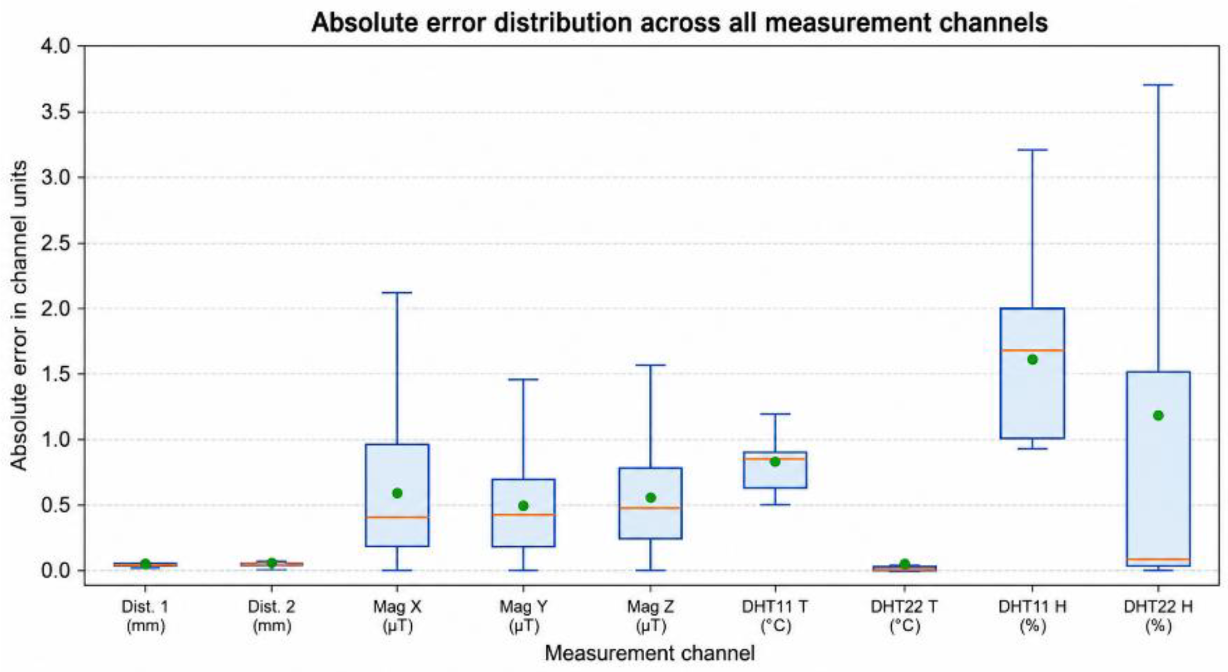
Figure 12.
A brief comparison of the average absolute and average square errors for all measurement channels of the developed monitoring system.
Figure 12.
A brief comparison of the average absolute and average square errors for all measurement channels of the developed monitoring system.
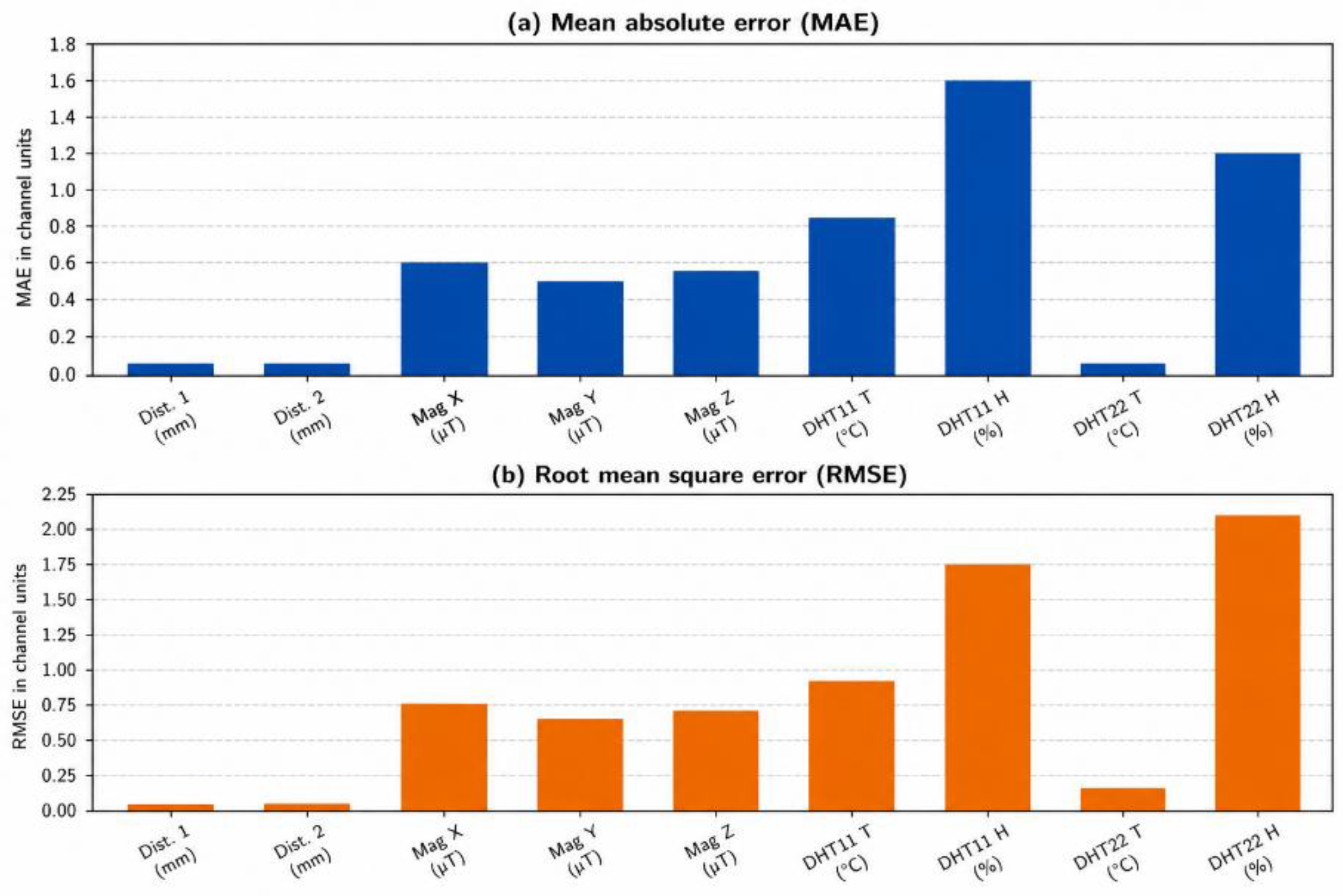

Table 1.
Comparative analysis with existing SHM architectures.
| Architecture | Communication Type | Data Processing | Scalability | Reliability |
|---|---|---|---|---|
| Centralized wired SHM [28] | Wired | Centralized | Low | Medium |
| ZigBee-based WSN SHM [29] | IEEE 802.15.4 | Partially distributed | Medium | Medium |
| Cloud IoT SHM [30] | Wi-Fi / LPWAN | Centralized | High | Medium |
| Proposed architecture | Wi-Fi Mesh | Edge + Distributed | High | High |
Table 2.
Comparison of SHM network architecture with classical MANET architectures.
| Parameter | AODV [31] | OLSR [32] | DSR [33] | Proposed Architecture |
|---|---|---|---|---|
| Type | Reactive | Proactive | Reactive | Hybrid |
| Energy awareness | No | No | No | Yes |
| Scalability | Medium | High | Medium | High |
| QoS support | Limited | Limited | None | Yes |
| Convergence | Medium | Fast | Slow | Fast |
| Suitability for SHM | Partial | Partial | No | Yes |
Disclaimer/Publisher’s Note: The statements, opinions and data contained in all publications are solely those of the individual author(s) and contributor(s) and not of MDPI and/or the editor(s). MDPI and/or the editor(s) disclaim responsibility for any injury to people or property resulting from any ideas, methods, instructions or products referred to in the content. |
© 2026 by the authors. Licensee MDPI, Basel, Switzerland. This article is an open access article distributed under the terms and conditions of the Creative Commons Attribution (CC BY) license (http://creativecommons.org/licenses/by/4.0/).
Copyright: This open access article is published under a Creative Commons CC BY 4.0 license, which permit the free download, distribution, and reuse, provided that the author and preprint are cited in any reuse.


