

Submitted:
09 June 2026
Posted:
10 June 2026
You are already at the latest version
Abstract
To solve the drawbacks of conventional long-cycle wear tests for miniature standing- wave linear ultrasonic motors, an accelerated equivalent wear model and test system were proposed in this work. After primary screening of multiple friction pair materials, graphite and Al2O3 were adopted to modify epoxy films. The optimal friction pair is composed of 6061 hard anodic oxidation film and ECA105 composite film. The matched pair exhibits excellent driving stability and low wear loss, with fatigue wear as the main wear form. Graphite and Al₂O₃ exert synergistic anti-wear and load-bearing effects via forming a stable transfer film on the friction interface. Experimental results confirm that the accelerated test is equivalent to full-life durability test. The presented method and optimized friction pair can effectively guide the development of high-performance ultrasonic motors.
Keywords:
standing-wave linear ultrasonic motor
; friction pair
; accelerated equivalent test
; modified epoxy film
; wear mechanism
1. Introduction
Friction material is a critical factor affecting the performance of ultrasonic motors [1,2,3,4,5], which directly determines the output driving force and wear life of friction pairs [6]. At present, five types of friction pairs polymer–ceramic [7,8], polymer–metal [9], metal–metal [10,11], metal–ceramic [12,13], and hard-coated ceramic–ceramic pairs [14] are applicable to standing-wave linear ultrasonic motors [15,16,17]. Tokyo Institute of Technology [7] fabricated modified polymer sliders via 3D printing and matched them with ceramic counterparts to investigate the regulation law of surface micro-texture on interfacial friction coefficient, with the friction coefficient improved by 45.5%. Nanjing University of Aeronautics and Astronautics (NUAA) [8] adopted multi-filler modified polyimide (PI) as the stator friction layer paired with micro-arc oxidation treated aluminum alloy, and explored the influence of molybdenum disulfide content on the tribological performance of PI composites. Worcester Polytechnic Institute [9] configured friction pairs consisting of Ultem-PTFE against Cu–Al alloy. Experimental results reveal that friction coefficient and surface roughness exert remarkable effects on the motor output torque. NUAA and University Teknology Malaysia [10] employed textured phosphor bronze paired with hard aluminum alloy to study the action mechanism of groove textures. Another research group from NUAA [11] selected beryllium bronze matched with hardened alumina; the friction coefficient was increased via interface modification, raising the motor efficiency from 36.8% to 46.3%. A collaborative research by Beihang University and Jiangsu University [12] studied the tribological behaviors of Al2O3 ceramic–aluminum alloy friction pairs, indicating that preload and contact stiffness can change interfacial work consumption and material wear loss. Israel’s Nanomotion Ltd. [13] developed ultrasonic motors using Al2O3–Al2O3 all-ceramic friction pairs, achieving a service life of 20000 h, driving force of 4 N and moving speed of 250 mm/s. Researchers at NUAA [14] prepared coatings containing 4 wt% CeO₂ on the surface of stator driving feet by atmospheric plasma spraying, and the obtained coatings possess excellent wear resistance. Taking V-type ultrasonic motors as research objects, Harbin Institute of Technology (HIT) verified that the silicon nitride–alumina combination delivers minimum wear coefficient [18,19,20,21,22]. The dominant wear mechanisms of materials include micro-fracture, surface fatigue and abrasive wear.
Due to the complex tribological behaviors at ultrasonic contact interfaces and unique component proportions of friction materials, existing theoretical studies [22,23,24,25,26] and test approaches [27,28,29] have limited reference value. Hence, wear experiments are essential to reveal wear evolution rules and improve the stability and service life of ultrasonic motors. Scholars worldwide have developed various simulative test rigs based on longitudinal-bending vibrators to support the research of friction materials. Yamaguchi [30] adopted a standing-wave linear ultrasonic motor as the simulation driving system and obtained the optimal preload for mild wear on the motor driving foot. P. Rehbein [31,32] developed a slider–Langevin transducer tribometer, proposed an evaluation method for friction pairs under high-frequency vibration, and characterized the tribological properties of polymer–steel and ceramic–ceramic mating pairs. J. Padgurskas [33] built a test bench for ultrasonic piezoelectric actuators to explore how friction pair combinations affect the tribological features of standing-wave motors and evaluate component wear severity. Yao [34,35] developed a dedicated tribological tester for standing-wave linear ultrasonic motors, clarified the variation law of stator foot wear rate with preload and relative sliding speed, and analyzed interfacial friction and wear characteristics. Qu [22,36,37] developed multiple simulative test devices capable of reproducing practical operating conditions to investigate the influences of external load, operating parameters and rotor friction materials on driving and tribological performances. Sujeet [38] and Cheng[39] designed high-frequency friction simulation setups for tribology research and friction pair screening, whereas the effect of ultrasonic vibration frequency was not involved in their work.
The research object of this paper is a miniature longitudinal-bending composite tuning-fork ultrasonic motor [40] operating under low-order vibration modes, as shown in Figure 1. Designed for integration inside mobile phone camera modules, its driving foot has a tiny radius of r=0.7 mm. Benefiting from the extremely small contact zone between stator and rotor, experiments simulating practical working conditions feature long test cycles, high costs and poor repeatability, which makes such methods unsuitable for friction pair screening. Most existing test equipment is customized for standard-size structures and fails to satisfy the test requirements of miniaturized friction pairs with low-order vibration; besides, several existing platforms ignore the impact of ultrasonic excitation frequency [38,39] and cannot meet the test demands for miniature friction pairs.In view of the above problems, an equivalent wear model of miniature friction pairs for ultrasonic motors is established in this work, and an accelerated wear equivalent tester is accordingly developed. Comparative screening tests are completed for 20 groups of friction pairs, and scanning electron microscopy (SEM) tests are carried out on specimens with modified EP films. Eventually, a transfer-film-based anti-wear theory is put forward. The research outcomes provide theoretical support and technical references for high-efficiency screening and long-life design of friction pairs for standing-wave linear ultrasonic motors.
2. Wear Model of Friction Pair
The TF motor investigated in this paper features compact dimensions, whereas the friction pairs of the equivalent test (ET) machine are relatively large. To screen out friction pairs matching the requirements of the TF motor via the tester, an equivalent wear model together with constraint conditions needs to be established.
2.1. Equivalent Wear Mode
The volume of adhesive wear V can be expressed as Eq. (1) in tribology theory.
where C denotes the wear constant, which depends on friction pair combination, surface condition and service operating condition. F is the contact load. L represents the sliding distance. H stands for material hardness.
When the friction pair and service condition are fixed, the wear loss of friction pair materials is directly proportional to the product of contact load and sliding distance. A larger contact load leads to significant material wear even over a short sliding distance. Let the wear volume of the driving foot for the TF motor be V1, and ET machine be V2. Assuming V1=V2, Eq. (2) can be obtained.
Based on the operating principles of the TF motor and ET machine, it can be deduced that C1≈C2, and H1=H2.Eq. (2) can be simplified to Eq. (3).
Therefore, when the contact load F2 of ET machine is larger than F1 of TF motor, the sliding distance L2 equired to produce identical wear can be reduced, which shortens the test duration. Consequently, accelerated wear and rapid screening can be realized.
2.2. Frictional Work Constraint
Frictional work parameter μpυ is one of the key indexes affecting wear performance, where p denotes contact pressure, υ is the relative velocity of contact surfaces, and μ represents the friction coefficient. Since the screening criteria for the ET machine need to be more stringent, p2υ2>p1υ1 needs to be constrained. According to the operating principle of the TF motor, the most severe wear occurs when the rotor is blocked. Under this condition, the relative sliding velocity equals the linear velocity of particles on the rotor surface, and υ is expressed as Eq. (4).
Υ=ωA=2πfA
The operating frequency of the TF motor is f1=80-100kHz, the amplitude A1=0.2-0.3μm, and the contact pressure p1=5Mpa. Theoretically, the operating frequency f2, amplitude A2, and contact pressure p2 of the ET machine should all exceed the above values to screen larger frictional work under harsher working conditions.
Nevertheless, the driving foot radius of the TF motor is only r=0.7mm, while the rotor radius Rs of ET machine is no less than 5 mm. Based on the empirical rule that larger structural size corresponds to lower vibration frequency and amplitude, it is difficult to satisfy f2>f1. To enable the equivalent tester equipped with a large-size rotor operating at low-frequency f2 to screen specimens matching the wear requirement of the small-size and high-frequency TF motor, ET machine must output higher vibration energy.To verify the hypothesis of frictional work constraint, two types of Langevin transducers are fabricated for wear experiments, shown in Figure 2.
Figure 3(a) reveals that, the vibration energy f×A decreases with the increase of vibration order N. Modal and harmonic response analyses indicate that higher frequency leads to lower vibration energy, as presented in Figure 3(b). In addition, the influence of transducer length L on f×A decreases progressively at lower N.
Both the TF motor and ET machine operate based on the first-order longitudinal bulk vibration and second-order local bending vibration. Accordingly, increasing either the length or diameter of the transducer improves vibration energy and frictional work, thereby accelerating material wear. Consequently, the equivalent tester produces more severe wear under stricter screening conditions and is applicable for screening tests.
2.3. Equivalent Evaluation of Driving Performance
Driving force Fd is one of the critical indicators characterizing the driving performance of ultrasonic motors. The maximum Fd of TF motor is 30mN, with a corresponding maximum preload of Fc=0.3N. But the Fd of ET machine is far higher, the minimum friction coefficient μumin is adopted for the equivalent evaluation of driving performance.By calculation of Eq. (5), the constraint condition μu>0.10 is obtained.
3. Equivalent Test (ET) Machine and Operating Parameters
3.1. Structural Principle
As shown in Figure 4, a reciprocating wear tester is developed for equivalent tester. To approximate the contact wear of the TF motor, an arc-shaped stator is used as the upper specimen (No.4) and a planar rotor serves as the lower specimen (No.7). The lower specimen is mounted on the low-friction guide rail (No.2), with reversing switches (No.1 and 8) arranged on both sides. The upper specimen is fixed on the driving end of the V-type ultrasonic motor (No.5), and spring assemblies (No.3 and 6) are employed to apply preload to V-type motor .
3.2. Parameter Configuration
To accelerate specimen wear and shorten experiment duration, the contact load of ET is set to 15 times the operating load of TF motor, which satisfies the equivalence requirement of frictional work. The original contact load of TF is F1=0.3N with a total sliding distance L1=2000m, while the accelerated test load of matched specimens on the screening tester is specified as F2=4.5 N. According to Eq. (3), the total sliding distance L2 of ET can be solved to achieve identical wear volume as the friction pair of TF motor. Given the single-stroke sliding distance S2=70 mm, the corresponding reciprocating cycle number N2 is further calculated.
Considering the reliability and technical feasibility of screening, N2 is fixed at 2000. Under the contact condition between cylinder and flat plane, the wear rate ωs of the driving foot can be expressed byvolume of the bow-shaped body, as shown in Eq. (8).
where ωs denotes the wear rate of the driving foot, Rs is the curvature radius of the stator of ET, bs represents the wear scar width of the upper specimen, Hs is the wear scar length, F2 stands for preload; L2 denotes sliding distance.
The working conditions of the screening test are specified as follows, ωs =5×10⁻⁶mm3 /Nm, Hs=2mm, Rs=5mm, F2=4.5N, L2=130m, Eq. (8) is adopted to calculate bsω=0.787mm.
Given that anodic oxidation is employed to enhance wear resistance, let the oxide film thickness be δ. The critical wear scar width bsA at the moment the oxide film is completely worn through can be calculated by Eq. (9).
Substituting δ=15 μm and Eq. (9) is adopted to calculate bsA=0.775 mm.
Therefore, the above configured parameters ensure bsω≈bsA. Specimens with and without anodic oxide films are evaluated under a unified assessment system, which consist of 4 evaluation indicators: average velocity υ, stall force Fd, wear scar width bs, and friction coefficient μu.
3.3. Primary Screening of Friction Pairs
Two types of aluminum alloys, 6061 and 2A12, are treated via hard anodic oxidation and denoted as 6061HAO and 2A12HAO, respectively, which serve as upper specimens in experiments. 20 groups of friction pairs are configured by matching the above upper with lower specimens including hard-coated stainless steel, non-ferrous metals, ceramics, epoxy polymer (EP) and modified films, listed in Table 1.
The comparative experimental results are shown in Figure 5. Excluding the wear scar width bs, combinations of high-hardness ceramics or metals paired with HAO coatings deliver a larger stall force Fd. From the perspective of comprehensive wear resistance, optimal friction coefficient μ ranges from 0.2 to 0.3. Lower μ will cause insufficient Fd, higher μ deteriorates the wear resistance of friction pairs accompanied by increase in bs.
It can be concluded from the above experimental results that the three rotor friction materials with high stall force Fd (hard coating, bulk ceramic and non-ferrous metal) induce severe wear bs on the stator oxide film, resulting in poor wear resistance for Groups 1-16. To simultaneously improve the driving performance of linear ultrasonic motors and the wear resistance of friction pairs, further investigations are required on the friction pairs composed of hard anodized aluminum alloy and EP films with varied compositions, corresponding to Groups 17-20.
4. Modification Test of Modified EP Film
4.1. Effects of Self-Lubricating Fillers
4 kinds of powder of graphite, molybdenum disulfide, PTFE and potassium borate are selected as fillers for EP films. Modified epoxy films are prepared with the filler dosage fixed at 15 wt% of epoxy resin, designated as EC15, EM15, EF15 and EBK15 respectively, and all powders are controlled at micron particle size. After the epoxy adhesive is thoroughly blended with different additives, the mixture is coated onto the surface of stainless steel lower specimens to form EP films. Screening experiments are carried out under identical other conditions, and the test results are presented in Figure 6.
The results reveal that incorporating the four types of solid lubricants into EP films leads to a slight rise in stall force Fd, while the average velocity υ barely changes. Among all combinations, the pairing of 6061HAO film and EC15 yields the minimum wear scar width bs of the HAO film, with a lowest value of only 0.447 mm and scarce wear debris along the scar edges; meanwhile, Fd reaches1.542 N, ranking at a relatively high level among the four filler-modified specimens. Further experimental data indicate that μ exceeds to 0.2 of the matching pair with 6061 anodic oxide film, satisfying the material selection criteria. It is demonstrated that graphite powder filled into EP films effectively improves the wear resistance of friction pairs, yet the ultrasonic driving force is marginally insufficient, which requires further optimization research.
4.2. EP-Film Friction Pairs by Graphite Fillers
5 groups of graphite-modified EP friction specimens denoted as ECX were fabricated via identical preparation processes, where X stands for the mass fraction of graphite powder blended into EP matrix. These specimens were paired with 6061HAO films to assemble friction pairs, and the experimental results are displayed in Figure 7.
Figure 7(a) reveals that Fd declines with rising graphite loading in EC films, yet the decreasing rate slows down once graphite content exceeds 10%. Υ varies mildly against graphite fraction and reaches a prominent peak at approximately 10% graphite addition. Figure 7(b) reveals that that bs of upper HAO specimens decreases markedly with increased graphite dosage following a trend similar to stall force, with a reduced declining rate after the 10% threshold. Figure 7(c) reveals that μfalls first and then rises to present a minimum value at 10% graphite content, whereas the μu decreases progressively and its descending tendency becomes gentle above 10% loading.
Wear morphology images of upper oxide films in Figure 8. It reveals that wear tracks on HAO films shrink obviously as graphite filler content increases. The unfilled HAO counterpart suffers severe abrasion with abundant wear debris accumulated along scar edges. Incorporation of 5% graphite leads to a remarkable reduction in wear scar width, and further graphite addition beyond 10% generates negligible difference.
It can be concluded from the above results that it is difficult to simultaneously optimize both the ultrasonic driving performance and the wear resistance of friction pairs. Therefore, the graphite content should be determined to achieve favorable wear resistance on the premise of guaranteeing acceptable driving performance. From the perspective of ultrasonic driving performance and manufacturing process, stall force declines and the epoxy slurry becomes excessively viscous for uniform coating once graphite loading exceeds 25 wt%. Accordingly, incorporating graphite at 10 wt% into epoxy matrix is the optimal formulation. Such EP composite film possesses superior self-lubricating capacity and effectively alleviates the wear of hard anodic oxidation films, yet it sacrifices ultrasonic driving output to a certain extent, which requires further improvement in follow-up research.
4.3. EP-Film Friction Pairs by Al2O3 Fillers
Existing studies have demonstrated that Al2O3 ceramic friction pairs can deliver high friction force. Table 2 illustrates that the incorporation of Al2O3 powder with varied mass fractions into EC films imposes a noticeable effect on the hardness of graphite-filled epoxy matrix. The wear test results are presented in Figure 9.
Figure 9(a) reveals that bs of the HAO film first decreases with rising Al2O3 content and reaches its minimum at 5 wt% Al2O3 with a reduction of approximately 3%, followed by a slow increase. It indicates that the addition of Al2O3 barely contributes to wear reduction of the anodic oxide film. In contrast, Fd rises initially and then declines as Al2O3 increases, peaking at 5 wt% with an increment of around 8% relative to EC10, which demonstrates that Al2O3 can improve the ultrasonic driving force.
Figure 9(b) reveals that υ drops after Al2O3 is incorporated into ECA10, yet it remains nearly constant upon further filler addition. The optimal improvement in stall force is achieved at the filler content of 5 wt%.
Figure 9(c) reveals that Al2O3 markedly elevates μ of EC10 and exerts a moderate effect on μu. At 5 wt% Al2O3, the μ is enhanced by about 64%, while the ultrasonic-driven μu rises by roughly 8%. Both coefficients decline slightly with further Al2O3 addition, yet the μu remains higher than μ. Consequently, the improved stall force after Al2O3 filling is attributed to the increased μu of the friction pair.
To further verify the above conclusion, scanning electron microscopy (SEM) characterization was carried out. Figure 10(a) presents the SEM morphology of the worn surface of ECA105 film. The worn surface is smooth with scarce scratches and clearly distributed filler particles. According to layered EDS mapping analysis shown in Figure 10(b) and Figure 10(c), abundant C, O, Al and Si elements are detected on the contact surface, whereas Au originates from the gold-sprayed conductive coating for SEM testing.It can be deduced that Al2O3 particles and substantial graphite accumulate on the worn track of ECA105 film. The high carbon content is derived partially from the epoxy resin matrix and partially from incorporated graphite powder. During friction against the 6061 HAO counterpart, embedded Al2O3 particles in ECA105 preferentially bear the applied load and rub against Al2O3 within the anodic oxide film, which raises the friction coefficient and accordingly enhances the ultrasonic driving force. Meanwhile, lamellar graphite with intrinsic self-lubricating property encapsulates partial Al2O3 grains and effectively restrains severe abrasive and adhesive wear on contact interfaces. Consequently, fatigue wear becomes the dominant wear mechanism, leading to reduced material loss of the friction pair.
5. Analysis and Discussion
5.1. Anti-Wear Mechanism of Filler-Modified EP Films
It can be concluded from the above analysis that the addition of appropriate content of graphite into epoxy films mitigates the wear of the mating pair composed of HAO film and EP film, yet slightly reduces Fd. To address this issue, 5 wt% Al2O3 was incorporated into EC10 film to prepare ECA105 composite film. When paired with 6061 HAO film, the friction pair achieves improved Fd and further reduced wear scar width on the upper anodic oxide specimen. The synergistic modification mechanism of EP films filled with graphite and Al2O3 is illustrated in Figure 11.
The friction and wear process between the stator and rotor can be divided into 3 stages. Figure 11(a) shows the initial contact stage. The contact surface of the stator is 6061HAO film, which is covered with pores with a diameter of approximately 5-10 μm. The conical pits represent these surface pores. Figure 11(b) presents the running-instate stage. A small amount of wear occurs on the asperities of the stator HAO film. Graphite on the mover EP film gradually aligns along the sliding direction and partially penetrates into the pores of the hard anodic oxidation film. Meanwhile, part of Al2O3 fills the pores, and the rest protrudes from the EP film surface.Figure 11(c) depicts the steady wear stage. The pores on the stator hard anodic oxidation film are gradually filled with the composite of epoxy resin, graphite and Al2O3, forming a thin transfer film on the stator surface. A concentrated layer of graphite and Al₂O₃ is also formed on the friction surface of the mover and distributes along the sliding direction. At this stage, friction takes place between the transfer film on the stator and the oriented composite layer on the mover EP film. This structure inhibits further wear of both the stator and EP film, and maintains a stable friction state.
To verify the above wear model, supplementary SEM observations and EDS elemental analysis of surface pores were conducted, as shown in Figure 12.
Figure 12(a) displays the morphology of the non-friction region, where micro-pores formed during hard anodization can be clearly observed with a size of approximately 5–10 μm. Such porous surface enables the embedding of micron-sized graphite and Al2O3 particles during friction with ECA105 film. As presented in Figure 12(b), a continuous covering film forms on the wear scar of the anodic oxide film, which protects the substrate from further abrasion. EDS results in Figure 12(c) confirm that the worn surface contains abundant carbon, aluminum and oxygen elements. Figure 12(d) shows the point scanning elemental analysis inside the pores in another wear scar area.
5.2. Durability Test of Wear-Resistant Friction Pairs
The wear-resistant friction pair consists of 6061HAO and ECA105 film. Its driving performance and wear life were investigated, and the results are shown in Figure 13.
Figure 13(a) indicates that υ remains stable during operation, ranging from 67.72 mm/s to 70.13 mm/s. The Fd also keeps steady, varying between 1.616 N and 1.89 N.
Figure 13(b) indicates that the friction pair undergoes a running-in stage followed by steady-state wear without severe abrasion. bs increases rapidly within the sliding distance of 0 to 500 m, and then enters the steady wear stage afterwards. bs rises slowly with increasing sliding distance, reaching 0.676 mm at 2040 m. The calculated wear rate per unit load and sliding distance is 2.88×10⁻⁶mm3/Nm. In terms of wear resistance, this friction pair meets the required service life.
Figure 13(c) indicates that μu fluctuates slightly and stays around 0.38. The μ also maintains a stable value of approximately 0.24. The results prove that the friction state remains reliable over the total sliding distance of 2000 m, and the pair satisfies the requirements for friction and driving performance.
Figure 14 presents the wear scar micrographs of the upper specimen in the wear-resistant friction pair. The results show that after 24,000 cycles, bs of HAO film on the upper specimen changes slightly. The wear surface is smooth, and its color is close to that of the non-contact area. Meanwhile, only a small amount of wear debris accumulates on both sides of the wear scar.
Figure 15 shows low-magnification SEM images of wear scars on the upper and lower specimens of the wear-resistant friction pair under different cycle numbers. As seen in Figure 15(a) and Figure 15(b), the wear morphology of the lower ECA105 film after 24,000 cycles is similar to that after 2,000 cycles at low magnification. Both surfaces are smooth with a discontinuous surface film formed, with no adhesion or ploughing wear. Figure 15(c) and Figure 15(d) reveal that the wear scar surfaces of the upper anodic oxide film remain smooth after both 2,000 and 24,000 cycles. The pores generated during hard anodization are barely visible, and no ploughing marks can be found. Combined with the analysis in Section 5.1, it can be concluded that the pores on the oxide film are covered by transferred substances from ECA105 film, forming a transfer film within wear region.
High-magnification SEM images were captured to further verify the formation of transfer films, as displayed in Figure 16. As shown in Figure 16(a) and Fig.(b), microcracks perpendicular to the sliding direction can be observed on the ECA105 film surface after 2,000 and 24,000 cycles under high magnification, which are typical characteristics of fatigue wear.On one hand, it indicates that friction occurs between the transfer film and the surface film of ECA105 film. The anodic oxide film is well protected against abrasion, and only mild fatigue wear takes place on ECA105 film with slight material loss overall. On the other hand, the wear mechanisms of the friction pair in the 2000-cycle accelerated screening test are highly consistent with those in the 24000-cycle long-term life test, both dominated by fatigue wear. This demonstrates that the screening test with low cycle numbers does not alter the wear mechanism and can be equivalent to the long-cycle life test. The proposed accelerated equivalent screening method is effective for friction pair material selection.
Figure 16(c) and Figure 16(d) presents the morphology of wear debris generated by the friction pair consisting of hard anodic oxide film and ECA105 film under two different cycle numbers. The debris appears as tiny flaky particles with a size of several micrometers, and the size of agglomerated debris is less than 10 μm. This further confirms the similarity of wear mechanisms. EDS analysis reveals that the debris is mainly composed of C, O and Al, indicating that it primarily originates from the worn ECA105 film, with a small portion derived from the upper anodic oxide specimen.
6. Conclusions
In this study, a design model for the friction pair of standing-wave linear ultrasonic motors is established, and a selection principle for the stator-rotor friction pair combination is proposed. Specifically, the stator material should possess higher hardness than the rotor, while the rotor material is required to have appropriate hardness and excellent self-lubricating performance. Such a matching design can effectively improve the tribological properties of the friction pair and satisfy the driving performance requirements of standing-wave linear ultrasonic motors.
An accelerated equivalent test method is further proposed for the rapid screening of friction pairs for standing-wave linear ultrasonic motors. Wear mechanism analysis verifies that the mover exhibits identical wear characteristics under both short-cycle accelerated tests and long-cycle life tests, dominated by fatigue wear. The results confirm the validity and feasibility of the proposed accelerated equivalent method, which provides a theoretical basis for the efficient selection and performance evaluation of ultrasonic motor friction pairs.
A high-performance wear-resistant friction pair consisting of a 6061 hard anodic oxidation (HAO) stator film and an Al2O3 / graphite synergistically modified epoxy (ECA105) rotor film is successfully developed. The assembled ultrasonic motor achieves excellent comprehensive performance in terms of driving stability and wear resistance. After a sliding distance of 2040 m, the wear scar width of the stator specimen is only 0.676 mm, and the corresponding wear rate is calculated as 2.88×10⁻⁶ mm³/(N·m), which fully meets the structural and service life design requirements of the motor.
The superior tribological performance of the optimized friction pair is attributed to the synergistic anti-wear effect of graphite andAl2O3 fillers in the ECA105 composite film. During the friction process, graphite components transfer from the rotor surface to the stator HAO film and form a uniform protective transfer film, while residual graphite on the rotor surface constructs a self-lubricating surface layer. Meanwhile, dispersed Al2O3 particles act as load-bearing skeletons to stabilize the ultrasonic driving force. The cooperative effect of self-lubricating graphite and load-supporting Al2O3 particles changes the dominant wear mode to mild fatigue wear, effectively inhibiting severe abrasive and adhesive wear and significantly improving the long-term service stability of the friction pair.
Author Contributions
Conceptualization, Qu H.J.; methodology, Qu H.J.; validation, Liang M.Q.; data curation, Liang M.Q.; writing—original draft preparation, Qu H.J.; writing—review and editing, Wen Z.P.; project administration, Wen Z.P.; funding acquisition, Qu H.J. All authors have read and agreed to the published version of the manuscript.
Funding
R&D Program of Beijing Municipal Education Commission 2024Z004-KWY-T.
Conflicts of Interest
The authors declare no conflicts of interest.
References
- Wang, G.; Yin, T.; Liu, Y. Reduction of adhesive wear and improvement of long-term stability in ultrasonic motors via DLC coating. Tribol. Int. 2025, 211. [Google Scholar] [CrossRef]
- Jianjun, Q.; Wenfeng, G.; Yanli, W. Effects of Wear of Friction Material on Performance of Ultrasonic Motor. Proc. Inst. Mech. Eng. Part J. J. Eng. Tribol. 2013, 227(4), 362–372. [Google Scholar]
- Song, F.; Yang, Z.; Zhao, G. Tribological Performance of Filled PTFE-based Friction Material for Ultrasonic Motor under Different Temperature and Vacuum Degrees. J. Appl. Polym. Sci. 2017, 134(39), 45358. [Google Scholar] [CrossRef]
- Zhu, Y.Y.; Qu, H.J.; Luo, M. Dry friction and wear properties of several hard coating combinations. Wear 2020, 203352, 456–457. [Google Scholar] [CrossRef]
- Zeng, S.; Li, J.; Zhou, N. Improving the wear resistance of PTFE-based friction material used in ultrasonic motors by laser surface texturing. Tribol. Int. 2019, 141, 105910. [Google Scholar] [CrossRef]
- Qu, J.J.; Zhang, Y.H.; Tian, X.; Li, J.B. Wear Behavior of Filled Polymers for Ultrasonic Motor in Vacuum Environments. Wear 2015, 322/323, 108–116. [Google Scholar] [CrossRef]
- Wu, J.; Mizuno, Y.; Tabaru, M. A 3D printed sandwich-type piezoelectric motor with a surface texture. Rev. Sci. Instrum. 2022, 93, 105003. [Google Scholar]
- Cao, X.X.; Zhao, G.; Li, X.M. Design and Research of Polyimide Friction Materials for Ultrasonic Motors. J. Vib. Meas. Diagn. 2025, 45, 791–796. [Google Scholar]
- Zhao, Z.; Wang, Y.; Bales, C. Finite Element Modeling of Surface Traveling Wave Friction Driven for Rotary Ultrasonic Motor. arXiv 2024, arXiv:2409, 10707. [Google Scholar] [CrossRef]
- Hua, X.; Puoza, J.C.; Zhang, P. The influence of laser surface texture on the tribological properties of friction layer materials in ultrasound motors. Proc. Inst. Mech. Eng. Part J. J. Eng. Tribol. 2022, 236, 1123–1132. [Google Scholar] [CrossRef]
- Chen, H.; Ji, H.; Qiu, J. Improvement of energy conversion efficiency in traveling wave rotary ultrasonic motor by increasing friction coefficient. J. Intell. Mater. Syst. Struct. 2024, 35, 861–872. [Google Scholar] [CrossRef]
- Zhang, B.; Yuan, X.; Zeng, Y.; Lang, L.; Liang, H.; Zhang, Y. Dahl friction model for driving characteristics of V-shape linear ultrasonic motors. Micromachines 2022, 13, 1407. [Google Scholar] [CrossRef]
- Zumeris, J. Ceramic motor. U.S. Patent US08/618503, 1996. [Google Scholar]
- Zhang, A.H.; Ding, Q.J.; Zhao, G. Study on Tribological Properties of Cr2O3-TiO2 Coating and Its Application in Ultrasonic Motor. China Ceram. 2016, 52, 58–61. [Google Scholar]
- Zhang, Y.H.; Fu, Y.H.; Hua, X.J.; Quan, L.; Qu, J.J. Wear Debris of Friction Materials for Linear Standing-Wave Ultrasonic Motors: Theory and Experiments. Wear 2020, 448–449. [Google Scholar] [CrossRef]
- Peng, Q.; Zhou, J.; Zhou, Y. Mechanical Characteristics Regulation of V-Shaped Standing-Wave Ultrasonic Motors With Minimal Quantity Lubrication. Tribol. Trans. 2023, 66, 223–237. [Google Scholar] [CrossRef]
- Puoza, J.C.; Sakthivelsamy, R. Ultrasonic Motors Structural Design and Tribological Performance -A Review. Tribol. Online 2021, 16, 286–298. [Google Scholar] [CrossRef]
- Zhang, Y.H.; Fu, Y.H.; Hua, X.J.; Quan, L.; Qu, J.J. Characteristics and Attenuation Mechanism of Linear Standing-Wave Piezoelectric Motors with Ceramics-Mated Friction Couples. Tribol. Int. 2021, 153, 106580. [Google Scholar] [CrossRef]
- Zhang, Y.H.; Jin, X.D.; Yuan, X.H. Measurement and Evaluation on Mechanical Performances of Standing-Wave Piezoelectric Motor of V-shaped Sandwich-Type Transducer Having Arc Tip. Measurement 2022, 190, 110766. [Google Scholar] [CrossRef]
- Zhang, Y.H.; Fu, Y.H.; Hua, X.J.; Quan, L.; Qu, J.J. Wear Debris of Friction Materials for Linear Standing-Wave Ultrasonic Motors: Theory and Experiments. Wear 2020, 448/449, 203216. [Google Scholar] [CrossRef]
- Zhang, Y.H.; Qu, J.J.; Wang, H. Wear Characteristics of Metallic Counterparts under Elliptical-Locus Ultrasonic Vibration. Appl. Sci. 2016, 6, 289. [Google Scholar] [CrossRef]
- Zhang, Y.H.; Qu, J.J.; Li, J.B. Friction and Wear Behavior of Linear Standing-Wave Ultrasonic Motors with V-shape Transducers. Tribol. Int. 2016, 95, 95–108. [Google Scholar] [CrossRef]
- Ishii, T.; Matsuo, E.; Nakamura, K. Characteristics of Ultrasonic Motors Driven in a Vacuum. Jpn. J. Appl. Phys. Part 1 1998, 37, 2956–2959. [Google Scholar] [CrossRef]
- Ishii, T.; Nakamura, K.; Ueha, S. A Wear Evaluation Chart of Friction Materials Used for Ultrasonic Motor. In IEEE Ultrasonics Symposium, Sendai, Miyagi, Japan, 1998, 699-702.
- Zhou, L.F.; Yao, Z.Y.; Dai, S.C. Modeling and Verification of Life Prediction of a V-shaped Linear Ultrasonic Motor. Rev. Sci. Instrum. 2021, 92, 045003. [Google Scholar] [CrossRef]
- Zhou, L.F.; Yao, Z.Y.; Dai, S.C. Modeling and Validation of Preload Force Effect on Characteristics of a V-shaped Linear Ultrasonic Motor. J. Intell. Mater. Syst. Struct. 2022, 33, 863–872. [Google Scholar] [CrossRef]
- Yang, L.; Wang, F.; Zhang, J. Remaining Useful Life Prediction of Ultrasonic Motor Based on Elman Neural Network with Improved Particle Swarm Optimization. Measurement 2019, 143, 27–38. [Google Scholar] [CrossRef]
- Li, J.B.; Liu, S.; Qu, J.J. A Contact Model of Traveling-Wave Ultrasonic Motors Considering Preload and Load Torque Effects. Int. J. Appl. Electromagn. Mech. 2018, 56, 151–164. [Google Scholar] [CrossRef]
- Li, J.B.; Qu, J.J.; Zhang, Y.H.; Wang, J.X. Mechanical and Electrical Characteristics of Traveling Wave Ultrasonic Motors During the Whole Life of Friction Material. Proc. Inst. Mech. Eng. Part J. J. Eng. Tribol. 2016, 230, 907–918. [Google Scholar] [CrossRef]
- Yamaguchi, T.; Adachi, K.; Ishimine, Y. Wear Mode Control of Drive Tip of Ultrasonic Motor for Precision Positioning. Wear 2004, 256, 145–152. [Google Scholar] [CrossRef]
- Rehbein, P.; Wallaschek, J.; Lhe, D. A Test Method to Investigate the Tribological Behaviour of Friction Materials under Ultrasonic Fretting Conditions. Tribotest 1999, 6, 3–16. [Google Scholar] [CrossRef]
- Rehbein, P.; Wallaschek, J. Friction and Wear Behaviour of Polymer/Steel and Alumina/Alumina under High-Frequency Fretting Conditions. Wear 1998, 216, 97–105. [Google Scholar] [CrossRef]
- Padgurskas, J.; Zunda, A.; Andriusis, A. The Effect of Fluorine Oligomer Coatings on the Tribocontacts of a Piezoelectric Actuator. J. Frict. Wear 2014, 35, 1–6. [Google Scholar] [CrossRef]
- Zhang, J.; Yao, Z.Y. Friction and Wear Test Device of Linear Ultrasonic Motor and Experimental Studies. In Proceedings of the 2010 Symposium on Piezoelectricity, Acoustic Waves and Device Applications, 2010, 72-77.
- Zhao, W.T.; Yao, Z.Y.; Wang, X.N. Friction and Wear Test Device of Linear Ultrasonic Motor and Experimental Studies. In Proceedings of the 2011 Symposium on Piezoelectricity, Acoustic Waves and Device Applications, SPAWDA 2011, 8-72.
- Qu, Y.Y.; Zhang, Y.H.; Qu, J.J. Micro-Driving Behavior of Carbon-Fiber-Reinforced Epoxy Resin for Standing-Wave Ultrasonic Motor. Polym. Compos. 2016, 37, 2152–2159. [Google Scholar] [CrossRef]
- Yan, C.; Ding, Q.J.; Xu, J.P. Research on Durability Performance of Novel Double Solution Grouting Material with Metakaolin. Adv. Mater. Res. 2011, 250-253, 722–727. [Google Scholar] [CrossRef]
- Sinha, S.K.; Thia, S.L.; Lim, L.C. A New Tribometer for Friction Drives. Wear 2007, 262, 55–63. [Google Scholar] [CrossRef]
- Cheung, C.K.; Shi, B.; Lau, C.S. Investigating the Effect of Surface Coatings on the Wear Behaviour of the Friction Contact in Ultrasonic Motors. Proc. Inst. Mech. Eng. Part J. J. Eng. Tribol. 2010, 224, 989–996. [Google Scholar] [CrossRef]
- Qu, H.; Liu, C.Y.; Zhang, L. A Longitudinal-Bending Hybrid Linear Ultrasonic Motor and Its Driving Characteristic. Shock Vib. 2022, 2022, 1–14. [Google Scholar] [CrossRef]
Figure 1.
Longitudinal-bending composite tuning-fork ultrasonic motor (TF motor) [40].
Figure 1.
Longitudinal-bending composite tuning-fork ultrasonic motor (TF motor) [40].
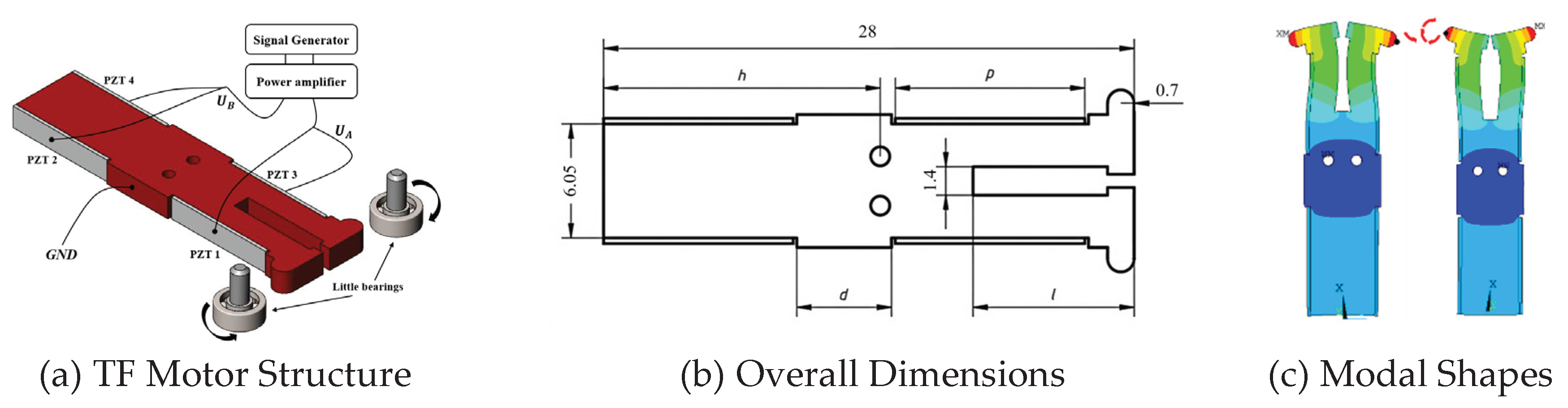
Figure 2.
Schematic diagram of two kinds of Langevin vibrator.
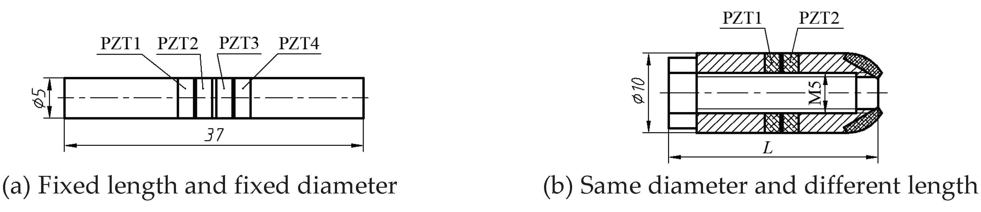
Figure 3.
Vibration energy under different vibration order and vibrator length.
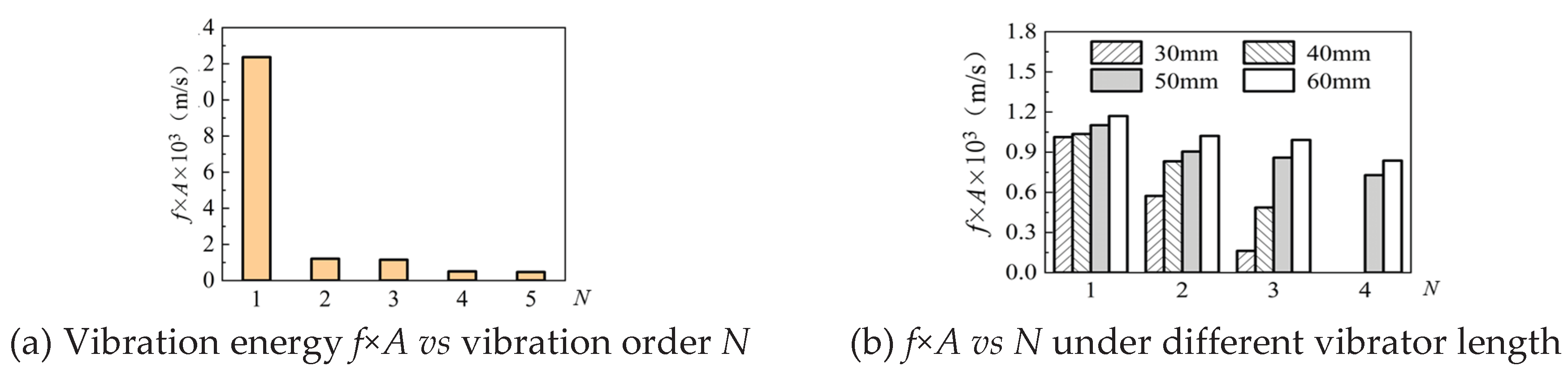
Figure 4.
Experimental principle, apparatus, and friction pairs structure.
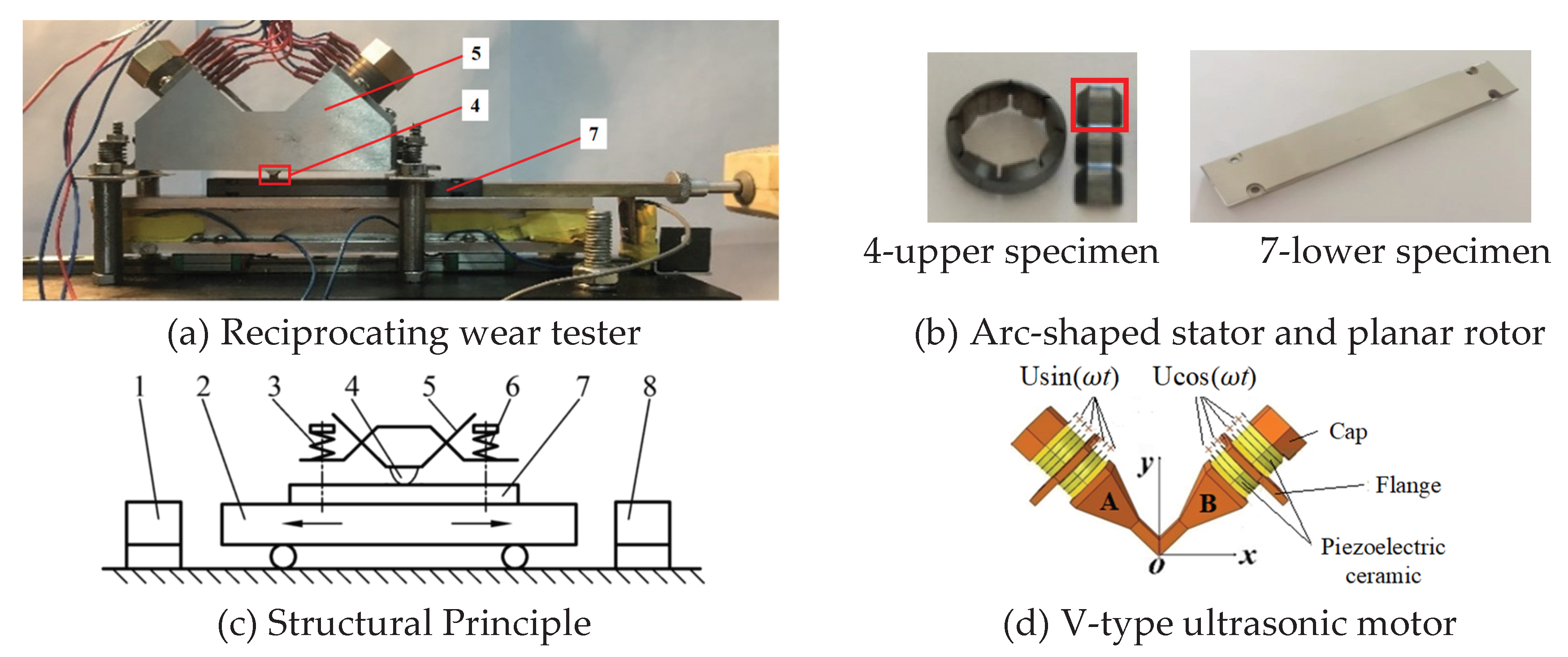
Figure 5.
Wear results of 20 groups of friction pair materials.
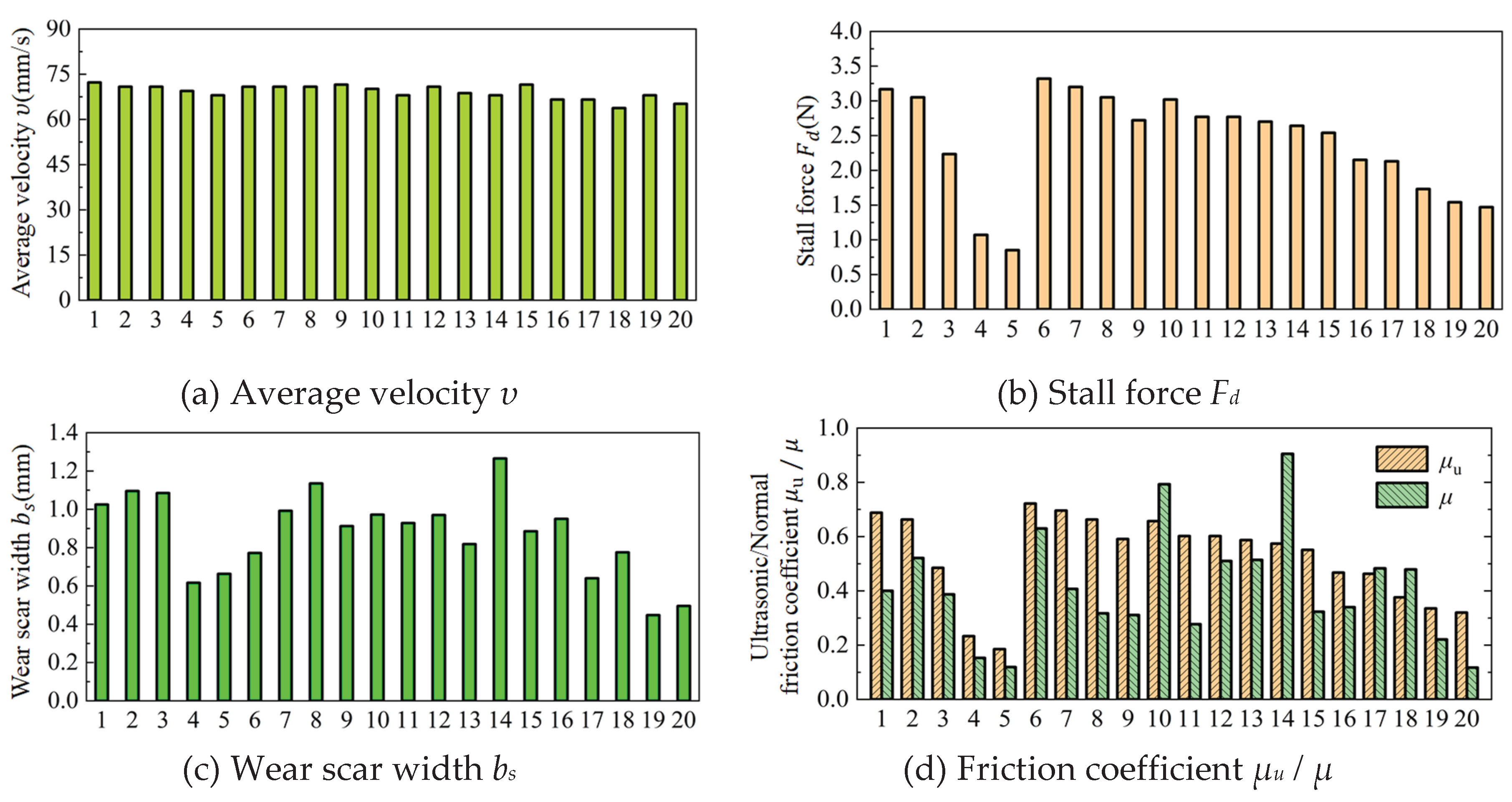
Figure 6.
Modification effect of self-lubricating filler on EP film.
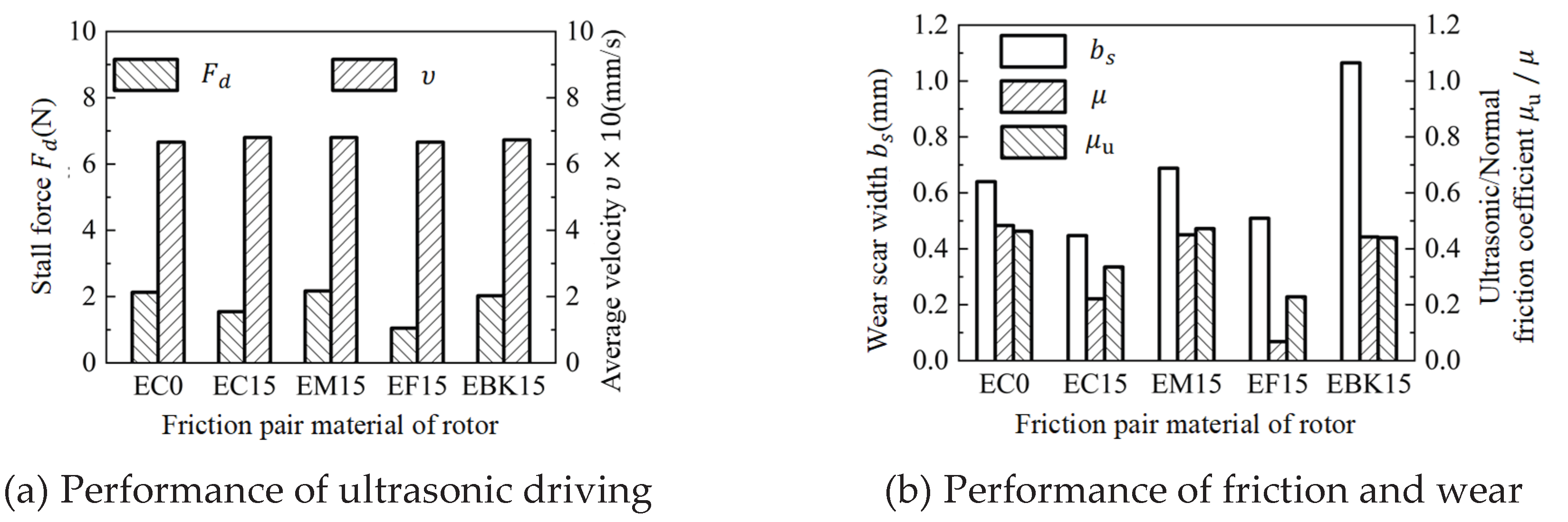
Figure 7.
Influence of Graphite Content on Friction Properties.
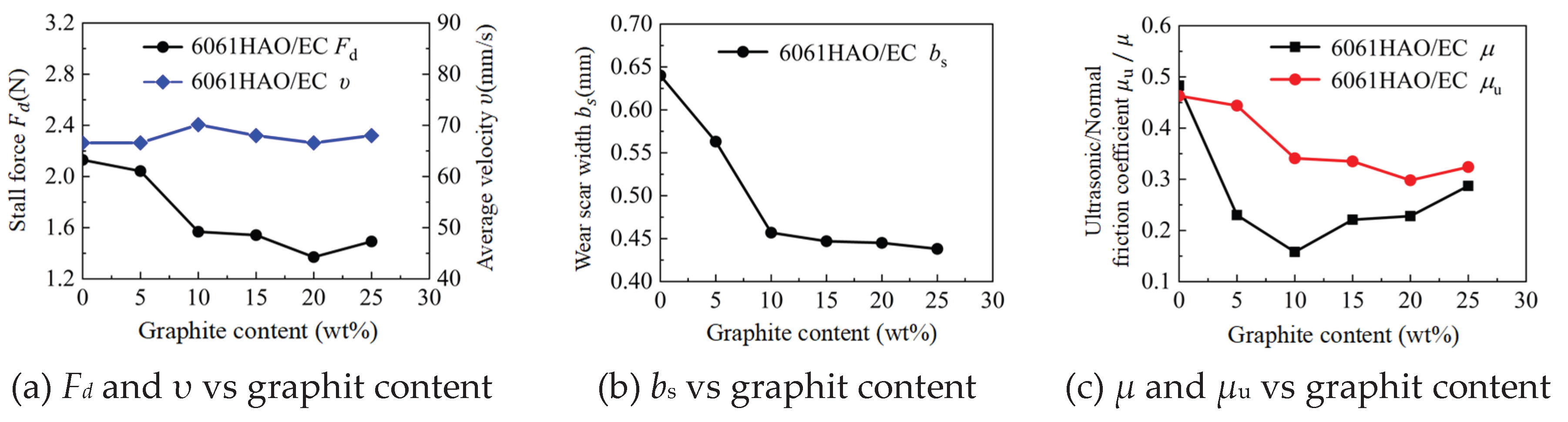
Figure 8.
Wear status of 6061HAO film and C-modified epoxy resin film.
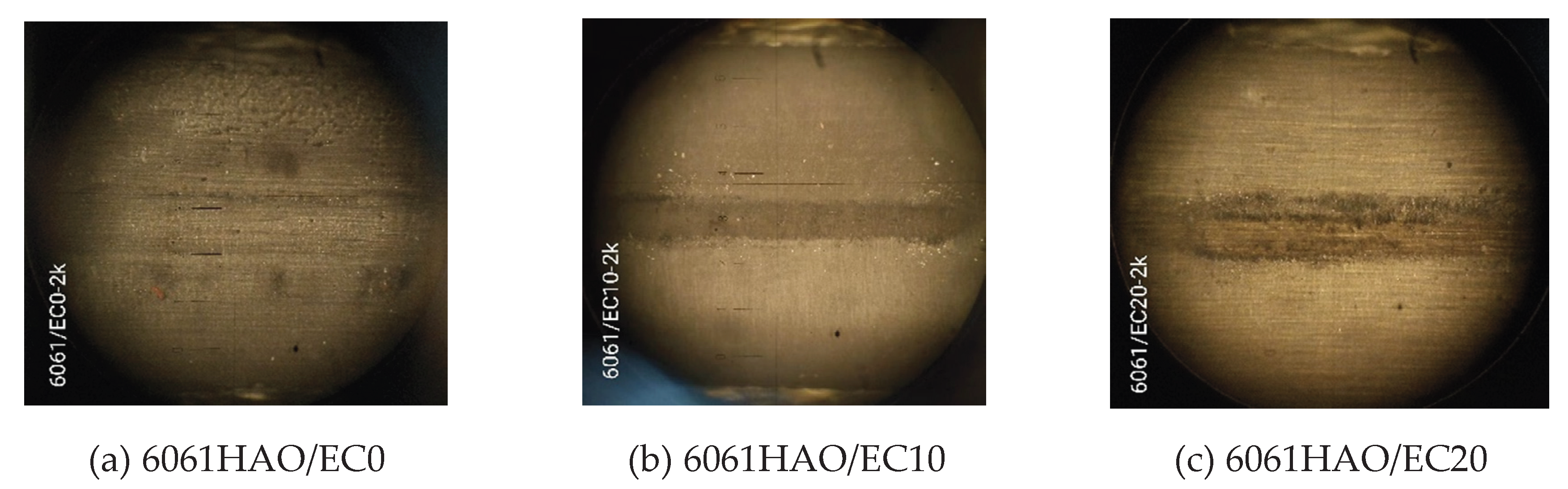
Figure 9.
Influence of Al2O3 Content on Friction Properties.
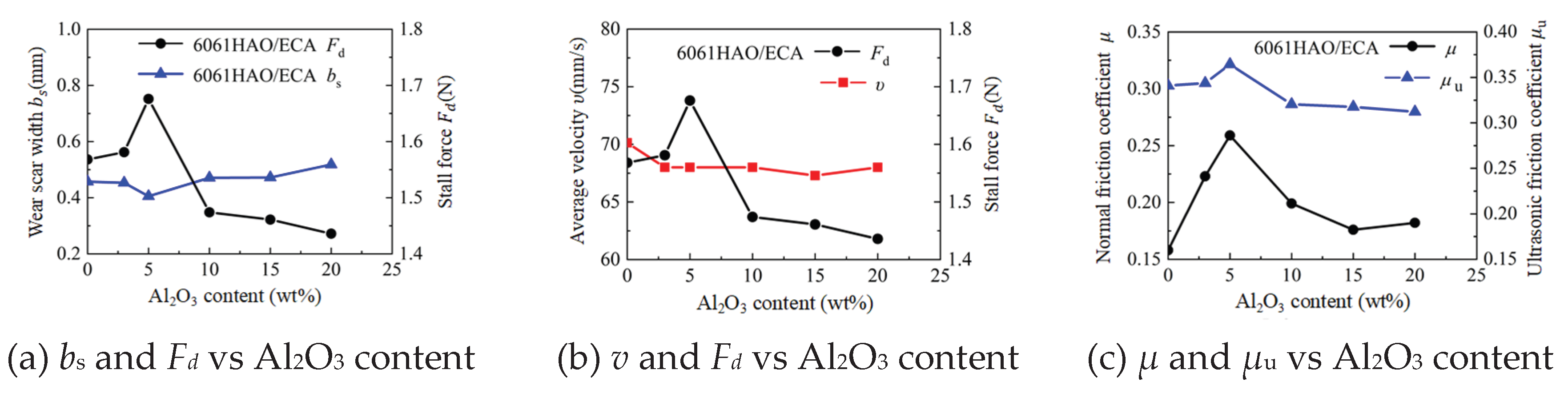
Figure 10.
SEM and EDS spectrum of Al2O3-modified EP film slider material.
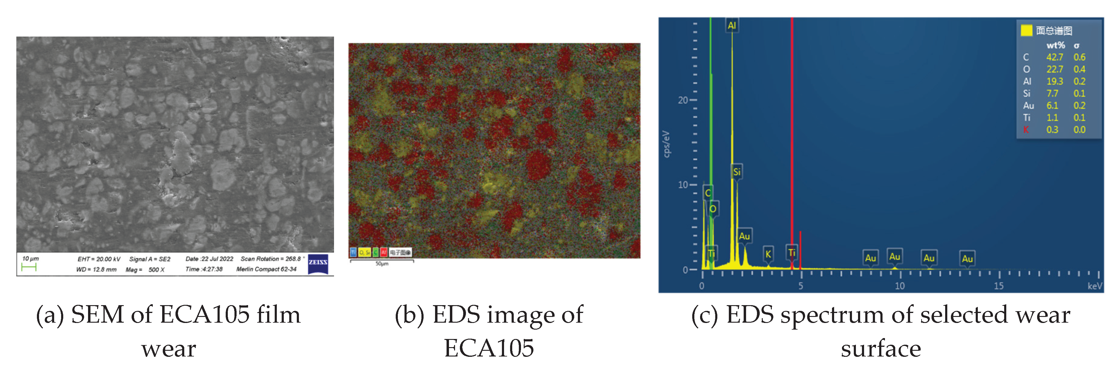
Figure 11.
Wear model of stator and slider.
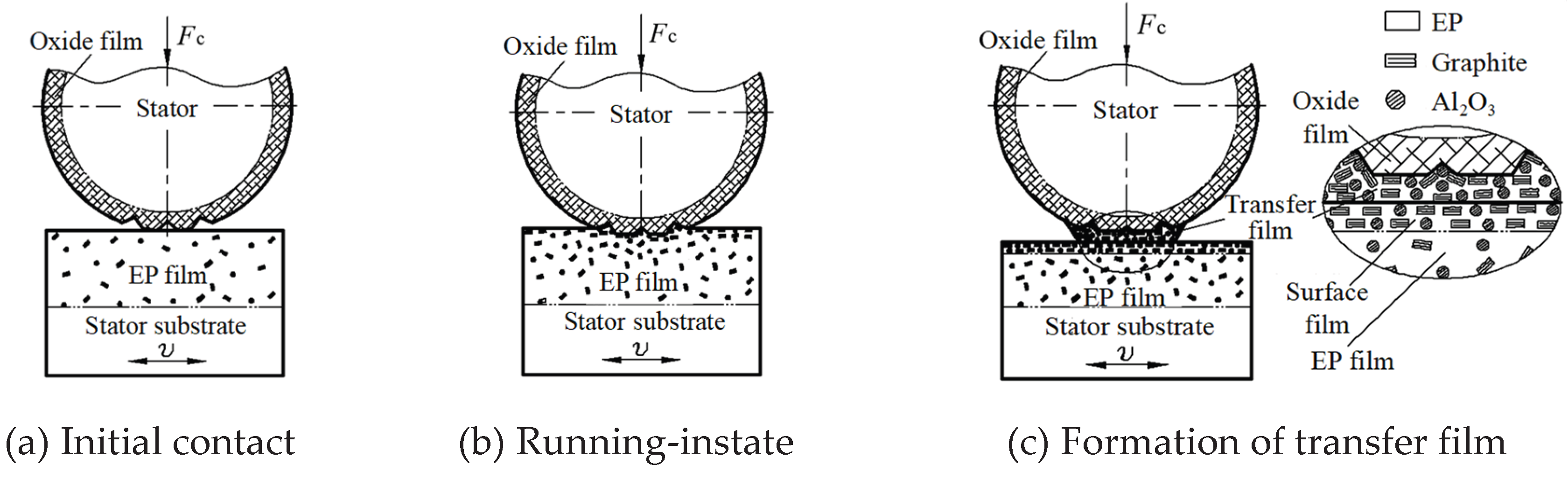
Figure 12.
SEM and EDS analysis spectrum of wear area and hole of oxide film on upper sample.
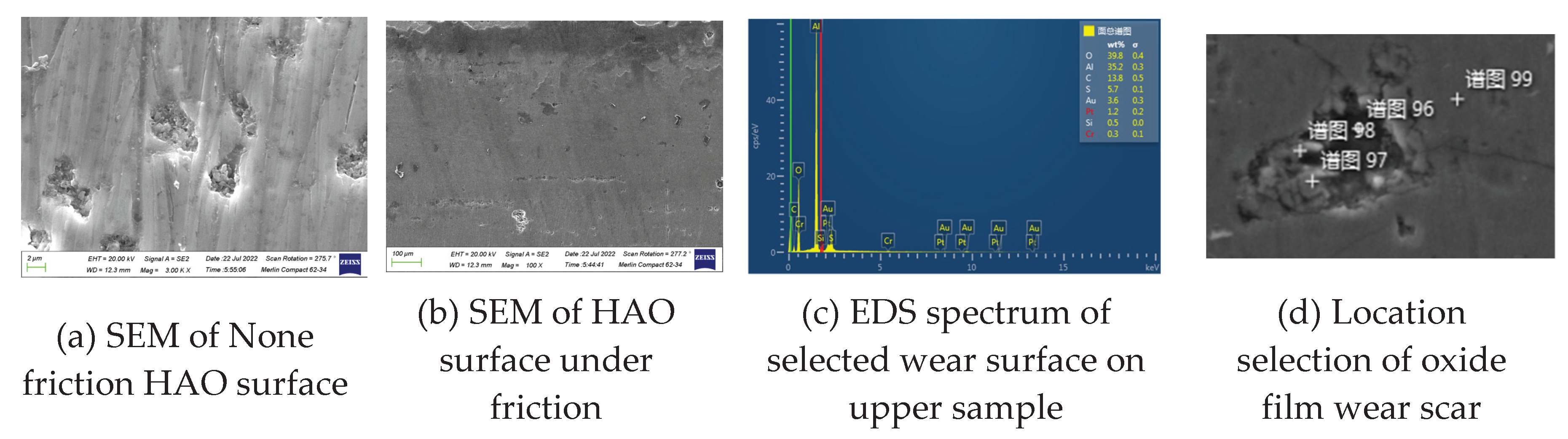
Figure 13.
Driving Performance and Wear Life Test of 6061HAO & ECA105 Friction Pairs.
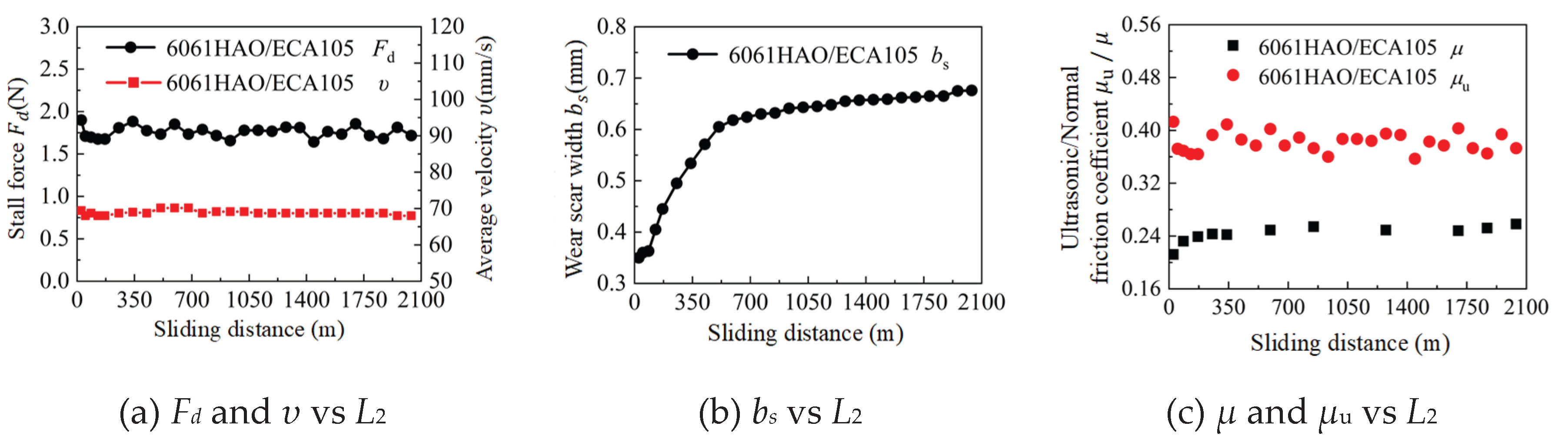
Figure 14.
Photos of wear scars of upper samples of the wearproof friction pair.
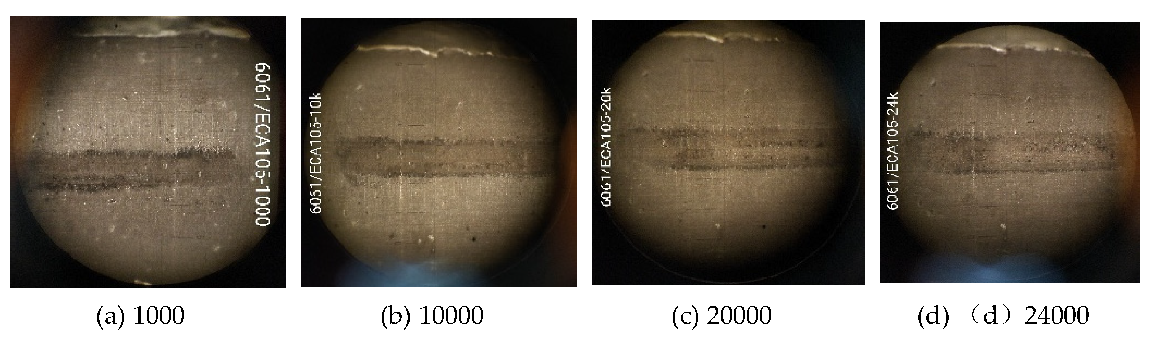
Figure 15.
Low-magnification SEM images of wear scars.
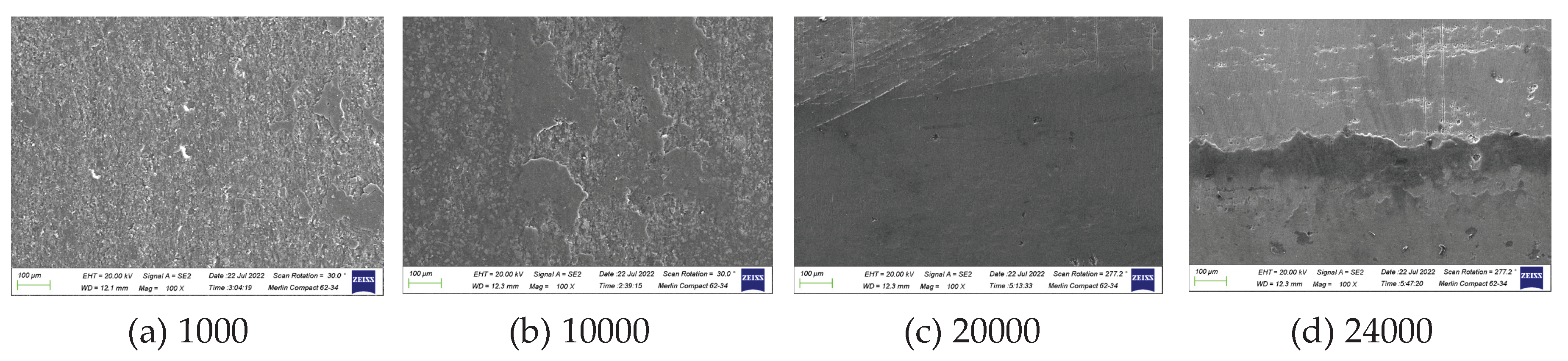
Figure 16.
High-magnification SEM and debris morphology under different cycles.
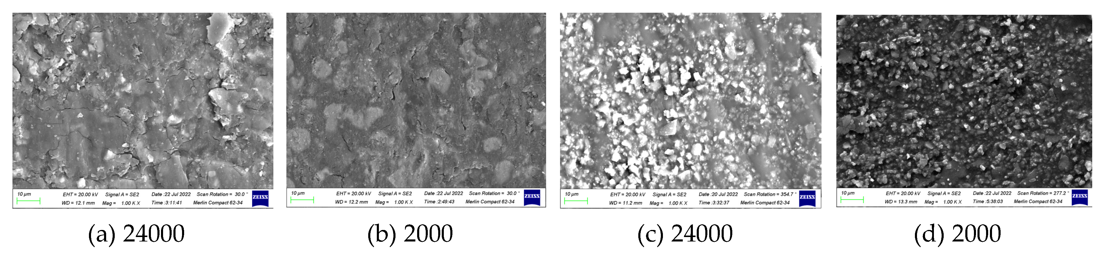

Table 1.
Number of friction pairs between HAO film and 20 kinds of slider materials.
| Number | Friction pairs | Material Types |
| 1 | 2A12HAO – 6061HAO | Hard anodic oxidation vs Hard-coated or non-ferrous metals |
| 2 | 6061HAO – CrN | |
| 3 | 6061HAO – TiN | |
| 4 | 6061HAO – DLC | |
| 5 | 2A12HAO – DLC | |
| 6 | 6061HAO – ZrO2 | Hard anodic oxidation vs Ceramics |
| 7 | 2A12HAO – ZrO2 | |
| 8 | 2A12HAO – Al2O3 | |
| 9 | 6061HAO – Al2O3 | |
| 10 | 6061HAO – Tag0.1 | Hard anodic oxidation vs epoxy resin coatings |
| 11 | 6061HAO – C1990 | |
| 12 | 6061HAO – C5191 | |
| 13 | 6061HAO – 925Ag | |
| 14 | 6061HAO – Sn&Ag&Cu | |
| 15 | 6061HAO – T663 | |
| 16 | 6061HAO – 99Ag | |
| 17 | 6061HAO – EC0 | Hard anodic oxidation vs EP and modified films |
| 18 | 2A12HAO – EC0 | |
| 19 | 6061HAO – EC15 | |
| 20 | 2A12HAO – EC15 |
Table 2.
Composition and hardness of ECA film.
| Friction pairs | Graphite Fillers(wt%) | Al2O3 Fillers(wt%) | hardness(HD) |
|---|---|---|---|
| EC10 | 10 | 0 | 84.2 |
| ECA103 | 10 | 3 | 84.3 |
| ECA105 | 10 | 5 | 85.1 |
| ECA1010 | 10 | 10 | 84.9 |
| ECA1015 | 10 | 15 | 84.8 |
| ECA1020 | 10 | 20 | 83.8 |
Disclaimer/Publisher’s Note: The statements, opinions and data contained in all publications are solely those of the individual author(s) and contributor(s) and not of MDPI and/or the editor(s). MDPI and/or the editor(s) disclaim responsibility for any injury to people or property resulting from any ideas, methods, instructions or products referred to in the content. |
© 2026 by the authors. Licensee MDPI, Basel, Switzerland. This article is an open access article distributed under the terms and conditions of the Creative Commons Attribution (CC BY) license.
Copyright: This open access article is published under a Creative Commons CC BY 4.0 license, which permit the free download, distribution, and reuse, provided that the author and preprint are cited in any reuse.