Submitted:
04 June 2026
Posted:
05 June 2026
You are already at the latest version
Abstract
Background
Efficient and safe instrument exchange remains an important challenge in robotic minimally invasive surgery. Current workflows require human assistance, increasing staff workload and contamination risk. The modular design of the AdLap robotic laparoscopic instruments enables automated exchange of instrument shafts. This study presents the development and validation of the Instrument Carousel Exchange System (ICES).
Methods
An automatic ICES was developed for the AdLap robotic surgery platform. The prototype was designed to hold six Shaft-Actuated Tip-Articulating (SATA) modular instrument shafts and focused on compactness, robustness, modularity, and rapid disassembly for cleaning and sterilization. System performance was evaluated using repeated autonomous instrument exchange cycles without user interaction. Reliability, alignment tolerance, safety, and exchange duration were assessed.
Results
The ICES prototype was successfully designed, manufactured, and tested. Repeated functional testing demonstrated reliable autonomous instrument shaft exchange without human intervention. The system tolerated minor alignment deviations while maintaining stable and safe operation. Mean time for a complete instrument shaft exchange was 84 seconds (SD = 10 seconds). The modular architecture allowed straightforward disassembly and maintenance while preserving structural integrity and compact design.
Conclusions
The developed ICES represents a substantial step toward fully automated robotic modular instrument handling in minimally invasive surgery. Automated instrument exchange may reduce staff workload and minimize contamination risk during robotic procedures. Future work will focus on improving automation speed, alignment efficiency, and autonomous reinsertion of the instrument shaft through the trocar to further enhance clinical applicability.
Keywords:
carousel system
; robotic surgery
; automation
; modular instruments
; sustainable surgery
; advanced
1. Introduction
Robot-assisted surgery (RAS) represents a significant advancement in medical technology, enabling surgeons to perform increasingly complex procedures with the assistance of robotic systems. These systems are designed to enhance surgical precision and dexterity, resulting in reduced risks of complications, shorter recovery periods, and improved clinical outcomes [1]. Technologies such as the da Vinci Surgical System have seen widespread adoption in fields such as urology, gynecology, and oncology, highlighting their versatility and impact on patient care [2]. Despite these advancements, RAS faces notable operational challenges, particularly in relation to the high demand for skilled surgical staff and the sterility requirements of the operating room environment [3,4]. Current robotic systems rely heavily on human intervention for tasks such as instrument handling and trocar docking. This human interaction with the instruments increases the risk of contamination, which could adversely affect patient outcomes [5]. With increasing costs and skilled worker shortages, hospitals have difficulties with staffing the operating room with scrub nurses. This results in postponed surgeries due to lack of staff, longer waiting times and increases health risks for the patient [6].
Numerous studies have focused on minimizing the reliance on skilled personnel within the operating room, particularly through a robotic scrub nurse [7,8,9]. These systems identify the required conventional laparoscopic instruments through prediction models, gestures or verbal commands and provide them to the surgeon. Some systems even partially insert the instrument in the trocar [10]. Although much of the research has been focused on laparoscopic surgery, the instrument selection and partial trocar insertion can potentially also be applied to robotic surgery.
Automatic instrument exchange implementation in RAS has different challenges depending on the subset of RAS. Within the field of microsurgery for ocular applications several studies present fully automated instrument exchange [11,12]. Whitin robot-assisted laparoscopic surgery (RALS) adaptable tool heads have been suggested rather than replacing entire instruments [13]. Carousel systems were also proposed and tested to present a Da Vinci instrument to an intermediate (scrub-nurse) [14]. The design of the Da Vinci systems, with all range of motion target around the trocar, prevents the arms from moving to a nearby carousel independently.
Figure 1.
Left) In situ visualization of the AdLap slave system. Middle) Close-up of a single arm with driver and instrument. Right) The AdLap end effector consisting of the driver and instrument.
Figure 1.
Left) In situ visualization of the AdLap slave system. Middle) Close-up of a single arm with driver and instrument. Right) The AdLap end effector consisting of the driver and instrument.

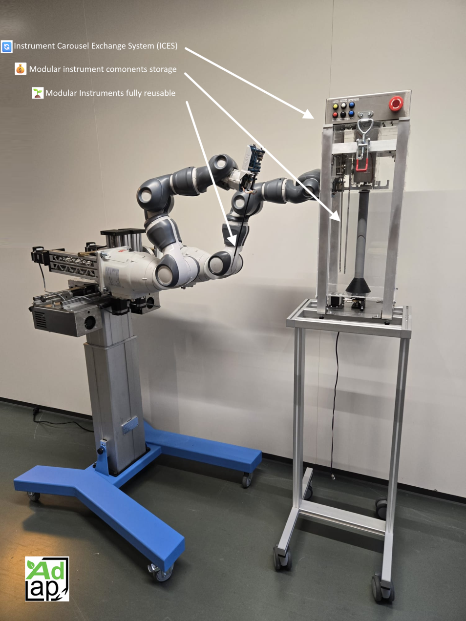
The AdLap project aims to develop as a fully modular “’waste free” surgical robot platform [15]. This platform makes use 7-DOF robotic arms and reusable 5 mm steerable instruments [16]. The system is inherently modular, allowing individual components to be exchanged independently (fig. 1). This modularity offers several advantages, including simplified cleaning, targeted repair or replacement of worn components and improved cost efficiency, resulting in a more sustainable product. Existing proposals for automated exchange systems in RALS have not yet utilized modular robotic instruments, leaving a clear gap for solutions tailored to component-level replacement. The aim of this study is to design and develop an automatic Instrument Carousel Exchange System (ICES) capable of automatically exchanging robotic surgical instrument shafts on the AdLap system without direct contact with the surrounding environment.
2. Methods
The AdLap system operates with fully reusable surgical instruments called Shaft-Actuated Tip Articulating (SATA) instruments. The 4-DOF instruments are driven by a newer generation of the SATA Drive [17]. In line with the modular nature of the instruments, the end effector is designed to be robotic platform independent (fig. 1 Right). In the current setup two robotic arms (YuMi IRB14050, ABB) are used to position the instruments (fig. 1 Left). The instrument shaft is driven through a gearbox that is connected to the motor unit. The instrument shaft and gearbox are connected via two coupling mechanisms that are normally operated by hand (fig. 2). The collet mechanism clamps the inner shaft of the instrument and transmits rotational motion and translation of the shaft. The shaft decoupling button locks two slots coupled to the external and middle shafts of the instrument, enabling articulation of the tip through shaft rotations. When pressed, the button decouples these shafts, allowing insertion or extraction of the instrument shaft, provided the collet is loosened.
The instrument shaft exchange in the AdLap system follows a defined sequence of steps to remove and replace SATA instruments. Figure 3 visualizes the interactions between the instrument shaft and driver to exchange an instrument shaft. A and B show where the manipulation actions of Figure 2 take place.
The Design Process
During RALS with this system, the workspace around the patient is highly constrained, as the anesthesiologist, scrub nurse, surgical assistant, and robotic system all require proximity to the operating field. This limited space restricts the possible placement of an instrument shaft exchange system and leads to the preference of a system with limited dimensions. The mechanical configuration and surgical staff define the operational workflow of the AdLap platform, leading to several functional requirements and performance criteria. The functional requirements guide the design of the instrument shaft exchange system by defining the essential tasks the system must perform and setting the framework for its design. The performance criteria complement this by enabling the systematic evaluation of the concepts generated later in the process. These criteria are applied in a Harris profile to assess the design concepts and support a weighted decision regarding which concept should be developed further. The full list of requirements and criteria as well as the full design process including concept selection and evaluation can be found in Supplemental file 1
Final Concept
From the three promising concepts in Supplemental file 1, the Durability concept stood out in speed and feasibility and was therefore selected to be developed into a prototype. The design can hold up to six instrument shafts (fig. 4). In alignment with the sustainability goals of the AdLap platform, the design can be (dis)assembled with generic tools. Components can easily be re-manufactured and are designed to be sterilized. Supplemental File 2 provides all details of the ICES and its sub-functions.
Testing Protocol
Various testing protocols were used to evaluate whether the prototype meets the defined functional requirements. In total, four tests have been established to verify these requirements. Additionally, some requirements are validated through expert observations or documentation rather than formal testing. A comprehensive overview of all requirements, acceptance criteria, and verification methods is provided in Supplemental file 1. The following tests were conducted: 1) (dis)assembly test, 2) Instrument shaft exchange cycle test, 3) Collet force test, 4) Instrument shaft snap-fit force test.
- 1)
- (Dis) assembly test
The installation test verifies whether the ICES can be safely assembled and disassembled in the correct order within the required five minutes. All individual components of the ICES and SATA instruments shafts are placed on a table, and the timer starts when the first part is picked up. After the ICES is assembled and powered on, the system should perform an automatic startup routine. Once completed, the SATA instrument shafts can be installed using the dedicated installation tool, ensuring correct orientation. The timer ends when the last SATA instrument shaft is installed. The experiment was repeated five times for both assembly and disassembly and performed by a trained operator. The detailed steps of the assembly process are explained in Supplemental file 3.
- 2)
- Instrument exchange cycle test
The main objective of this test was to demonstrate that the robotic arm with the SATA driver can successfully exchange an instrument shaft with the ICES without any errors. The functional requirements indicate that the exchange cycle must be completed within 60 seconds and that the ICES can detect if the robotic arm is correctly positioned for an instrument shaft exchange. The system should still be able to receive an instrument even if the docking is offset by 1mm or misaligned by 0.5° in orientation. For the test, a predefined step pattern was programmed into the robotic arm using ROS2. The ICES followed its own sequence during the exchange. Both sequences were manually triggered, with the robotic arm executing 5 steps per exchange and the ICES completing six steps as seen in Figure 3. The ICES verifies the position of the robotic arm with end effector after each step using TOF-sensors. The exchange cycle timing was measured from the moment the instrument shaft first contacted the carousel until it was fully removed from the snap-fit. The complete sequence was repeated six times under normal conditions and additionally 2 times with carousel rotation misalignments of approximately 0.5° in both directions and 2 times with 1mm shifts of the entire ICES to the left and right.
- 3)
- Instrument shaft snap-fit force test
To verify functional requirement two, which states that instruments can be manually removed from the carousel using less than 30N of force, a dedicated test protocol was developed. One test was done for pulling out the instruments from the holder and another for placing the instruments back in the holder (fig. 5). To ensure consistent force distribution and prevent removal at an angle, a small tool was developed to apply the force perpendicular to the instrument. The force required to insert or remove the instruments was measured using a spring balance (fig. 5). The tests were conducted as follows; The carousel contains six snap-fit locations. For each location, five insertion and removal trials were performed. Each trial was recorded by a camera and the maximum force value was noted.
- 4)
- Collet force test
To test that the collet provides a sufficient clamping force without slipping for proper actuation (pinching) of the instrument’s jaws. The pinching force at the instrument’s jaws was required to exceed 5N and was measured directly with a load cell (LSB201, Futek). The measured pinch force before slip relates directly to the strength of the collet-shaft connection after the ICES tightened the collet. The test is finished after the maximum current for the driver is reached or the shaft slips. The test was repeated five times to obtain an average maximal pinching force.
3. Results
A prototype of the automatic ICES was developed and successfully tested. An overview of the complete assembly is shown in Figure 4. The ICES enables automated exchange of SATA instrument shafts, without human intervention. The carousel accommodates six instrument shafts and completes a full exchange cycle in approximately 84 seconds. Manual operation is possible via six control buttons on the device’s housing, and an emergency stop button ensures operator’s safety. The ICES is fully modular, allowing it to be disassembled and reassembled in eight steps, which facilitates maintenance, cleaning, and rapid replacement of components. The overall dimensions of the carousel are 250 x 250 x 720 mm, with a total weight of 13kg.
Hardware and Manufacturing
All custom components of the ICES were produced in-house at the Faculty of Mechanical Engineering at TU Delft and off-the-shelf components were incorporated where appropriate. The gears of the collet mechanism, the two alignment blocks, the button pressing attachment with servo bracket and the snap-fit holders are all 3D-printed in PLA. The frame of the ICES was constructed from 30x30x2 mm aluminum, 3 mm laser-cut acrylic, a stainless steel baseplate and stainless steel control box on top. The commercially sourced internal gears that drive the carousel have a 40:1 ratio for a high positional accuracy of 0.045° per stepper pulse. The ICES is powered by a 12V/3A power supply and controlled by an Arduino Mega2560. To actuate the sub-function mechanics, two stepper motors (Nema17, 0.49Nm − 1.68A) and one servo (TD-8120MG) motor are installed. To control the stepper motors, two TMC2209 stepper drivers are used, along with a CNC board V3. These stepper drivers were specifically selected for their integrated StallGuard feature, which enables real-time load and stall detection. This capability is primarily utilized to achieve a consistent and repeatable locking of the SATA gearbox collet, which must be tightly clamped to effectively transmit actuation forces. To effectively control the ICES, two hall sensors and two TOF (Time-Of-Flight) sensors are implemented. The hall sensors are used to calibrate the device when starting up and zero out the shafts of the two stepper motors. The TOF sensors help detect the specific position of the SATA driver on the robotic arm in the instrument docking procedure. This ensures that the device only performs the selected procedure when the SATA driver is in the correct position. One is located right above the button mechanism, the other is located on top of the target collet location when exchanging an instrument shaft. A full overview of the electronics and code is available in Supplemental file 4.
Figure 5.
Top) Sequential view of the instrument shaft exchange cycle of the Instrument Carousel Exchange System (ICES). The yellow arrows show the movement of components and yellow circles highlight changes or important features. (1) The robotic arm docks the instrument shaft into the snap-fit. (2) The button mechanism pushes in the button, and the collet mechanism rotates to release the collet. (3) The collet mechanism rotates out of the way. (4) The robotic arm moves upward and away to release the instrument shaft. (5) The instrument carousel rotates to the next instrument shaft and the button mechanism retracts. (6) The robotic arm moves halfway down toward the new instrument shaft. (7) The button mechanism pushes in the button again. (8) The robotic arm moves fully downward into position. (9) The button mechanism releases the button. (10) The collet mechanism locks the collet by rotating until three steps are skipped. (11) The instrument shaft is fully installed, and the robotic arm can move away. Middle) Experimental setup used to measure the pulling and pushing force with a spring balance. Bottom) Experimental setup for measuring the pinching force at the curved Maryland tip to verify collet clamping strength. The instrument shaft is actuated by the SATA driver (driver shown on the left) while an LSB201 force sensor on the right records the pinching force. The collet clamping strength is evaluated as the maximum pinching force at the tip before slip occurs.

(Dis) Assembly Test
The installation time test was conducted five times following the eight-step assembly procedure using the designer as the participant. Across these trials, the instrument carousel was assembled in an average time of 188 (SD 30) s and disassembled in an average time of 59 (SD5) s (Figure 6A and B).
Instrument Exchange Cycle Test
The system was able to exchange instrument shafts automatically for ten repeated times without failure (fig. 5 top). The exchange time took on average 84 (SD 10) seconds and no manual interactions or software corrections were needed (fig. 6C). The 4 cases where slight misalignment occurred between the lodging parts did not add issues to the docking sequence.
Instrument Shaft Snap-Fit Force Test
The snap-fit force test was conducted on all six instrument shaft locations, with each position tested five times for both pushing and pulling actions (fig 5 middle). The average pulling force across all snap-fit holders was 16 (SD 3) N (fig. 6E) and the average pushing force was 14.6 (SD 2.8) N (fig. 6F).
Collet Force Test
The collet force test was conducted six times successfully (fig. 5 bottom). The progression of pinching force over time is shown in Figure 6D. During each trial, the SATA instrument jaws were gradually closed in discrete steps, resulting in a staggered increase in force. The average pinching force reached 5.2 (SD 0.3) N before slip occurred.
4. Discussion
This study shows that automated modular instrument exchange for robotic minimally invasive surgery is technically feasible using the developed Instrument Carousel Exchange System (ICES) integrated with the AdLap robotic platform. The ICES successfully enabled autonomous exchange of six reusable SATA instrument shafts without human intervention while maintaining stable and reliable operation throughout repeated testing cycles. The system demonstrated tolerance to minor alignment deviations, reliable collet engagement, and safe instrument handling, while preserving a compact and modular design that allows rapid disassembly, sterilization, maintenance, and component replacement. Repeated autonomous instrument exchanges were completed successfully with a mean exchange time of 84 seconds. Importantly, this study demonstrates the feasibility of combining modular reusable robotic instruments with automated robotic workflow support, representing an important step toward more intelligent and workflow integrated robotic surgical systems. An overview of all functional requirements, their verification method, and whether the requirements were met is provided in supplemental file 1. Observations confirmed that all contact points can be cleaned properly and the manual control interface functioned as intended.
The average instrument exchange time shows that the current setup is functional but does not reach the desired threshold of 60 seconds. The main limiting factor for exchange time was the lack of direct communication between the instrument carousel and the robotic system. Manually operating the buttons introduced delays between each stage. If the systems were to communicate with each other, the exchange process could become fully autonomous, reducing the exchange time and removing the chance of operator errors. To implement this, the Instrument ICES could be integrated in the ROS2 communication layer of the AdLap platform. Another factor that could improve the overall exchange time is increasing the movement speed of both the robot and the carousel. These motions were kept at conservative speeds during testing to ensure safe operation.
The instrument carousel has proven to be robust as all exchanges were completed successfully, including four cases where slight misalignment was created between the calibrated end effector position and the ICES. This shows that the mechanical tolerances and guiding features are sufficient to handle small positioning deviations without failure. Even though these deviations were allowed, setting up the robot in alignment with the ICES still takes up several minutes. Active self-calibration when dealing with larger misalignments could speed up setup times since positioning will need to be less precise. Adding more TOF sensors or a camera would allow the system to compensate for misalignment with the predicted position. This would also require integration of the ICES in the ROS2 communication layer of the AdLap platform.
The collet force test showed that the instrument achieved a pinching force of approximately 5N, which is lower than the specified 10N. In reality, the actual pinch force could be much higher as it turned out that the instrument shaft does not slip in the collet, but the drivers were current limited to prevent damage to the SATA motor unit. This was confirmed with an extra pulling test that showed that slip did not occur below a load of 10 Newton.
A significant portion of the installation time was spent installing each instrument shaft individually into the holder by cycling through all the slots. This process accounts for nearly half of the total time and could be significantly reduced by preloading the instrument shafts into the holder before assembly.. The snap fit tests showed a reduced pushing/pulling on one snap-fit location force compared to the others. This is likely due to material fatigue, as this snap-fit was heavily used during assembly, with more than 100 inserted and removed instruments. This likely caused minor deformations in the 3D printed PLA and slightly reduced the holding force. To improve the lifetime and consistency of the snap-fits, a more suitable material should be used such as ABS or PETG that offer greater toughness and elasticity. Beyond the technical feasibility demonstrated in this study, the ICES may have broader implications for future robotic surgical workflows and operating room automation.
Clinical Workflow Implications
Automated modular instrument exchange systems may have important implications for future operating room workflows and staffing models in robotic surgery. Current robotic procedures remain highly dependent on experienced scrub personnel, while operating room staffing shortages continue to increase worldwide. Recent robotic scrub nurse systems have demonstrated the feasibility of AI driven instrument anticipation and automated instrument delivery during minimally invasive surgery [7,8,9]. In parallel, increasing evidence shows that workflow disruptions during robot assisted surgery may negatively affect procedural efficiency and operative flow [20,21]. In this context, automated exchange systems such as the ICES may reduce dependency on highly specialized scrub nurses, improve workflow standardization, and minimize direct human contact with surgical instruments during exchange, potentially reducing contamination risk and improving operating room efficiency as robotic surgery volumes continue to increase.
Sustainability and Modular Robotic Surgery
An important strength of the ICES concept is its alignment with emerging sustainability goals in robotic surgery. Current robotic platforms mostly rely on disposable components and limited life instruments, contributing substantially to medical waste and procedural costs [22]. In contrast, the AdLap platform and ICES are based on reusable modular components that enable selective replacement, repairability, sterilization, and refurbishment of individual parts rather than complete instrument disposal. Previous work has already demonstrated the feasibility of reusable SATA instruments and modular robotic drivers with integrated sensing capabilities [17]. As healthcare systems increasingly prioritize environmentally responsible innovation, modular robotic systems may become increasingly relevant for sustainable minimally invasive surgery [16].
Autonomous Robotic Surgery Ecosystems
Beyond automated instrument exchange alone, the ICES may represent enabling infrastructure for future semi-autonomous and autonomous robotic surgical ecosystems. Integration with ROS2 communication, sensor based positioning, computer vision, and AI driven workflow recognition could facilitate coordinated robotic workflows with increasing levels of autonomy. Recent studies on robotic workflow recognition, autonomous task planning, and automated instrument insertion demonstrates the growing convergence of robotics, machine learning, and surgical workflow automation within the operating room [10,23,24,25,26]. Furthermore, broader frameworks describing levels of autonomy in surgical robotics increasingly identify workflow coordination and task automation as key enabling technologies for future autonomous surgical systems [27]. In this context, the ICES may be viewed not merely as an isolated exchange device, but as foundational infrastructure for intelligent and interconnected robotic operating rooms in which robotic systems autonomously coordinate both surgical manipulation and surrounding procedural logistics.
Future Work
Some components were deliberately over-engineered to ensure reliable functionality, resulting in a system heavier than necessary. Further weight reduction could improve handling and installation in a clinical setting. In addition, the current prototype lacks a clear status interface, making it difficult for the surgical team to identify whether the system is ready for instrument exchange or if an error has occurred. Integrating status indicators on both the ICES and the main console could improve usability and safety. Another important step toward improving performance is integration of the ICES with the broader robotic platform communication architecture. During testing, both the carousel and robotic arm operated at conservative speeds to ensure safe and controlled conditions. Direct communication between the systems would enable coordinated motion, potentially improving exchange speed, workflow efficiency, and operational safety by reducing unintended or conflicting movements. Future iterations may also benefit from integrated decontamination strategies to prevent blood and debris from drying on stored instrument tips. In combination with a slight overpressure within the sterile casing, this could further reduce contamination risk during storage. Together, these developments may help advance the ICES from a proof of concept toward a practical and reliable system for automated robotic instrument exchange in clinical practice.
5. Conclusion
The automatic Instrument Carousel Exchange System (ICES) prototype was designed and successfully validated for the AdLap surgical robotic platform with modular instruments. The system enabled reliable autonomous exchange of reusable SATA instrument shafts while maintaining safe and stable operation. Although further optimization of exchange speed and system integration is required, the ICES demonstrates the feasibility of automated modular instrument handling in robotic minimally invasive surgery. Future integration of such systems may contribute to more efficient, sustainable, and increasingly autonomous robotic operating room workflows.
Author Contributions
Conceptualization, Olaf Aartman, Roel Horeman, Koen Schouten, Tim Horeman-Franse ; methodology, Andres Hunt, Sem Frederik Hardon, Micah Prendergast, Tim Horeman-Franse.; validation, Roel Horeman Olaf Aartman ,Koen Schouten; formal analysis, Roel Horeman Olaf Aartman, Tim Horeman-Franse; investigation, Roel Horeman, Olaf Aartman , Sem Frederik Hardon, Micah Prendergast, Tim Horeman-Franse; resources, Andres Hunt, Micah Prendergast, Tim Horeman-Franse; data curation, Roel Horeman Olaf Aartman ,Koen Schouten; writing—original draft preparation, Olaf Aartman; writing—review and editing, Roel Horeman Olaf Aartman ,Koen Schouten, Andres Hunt, Sem Frederik Hardon, Micah Prendergast, Tim Horeman-Franse; visualization, Roel Horeman Olaf Aartman, Micah Prendergast, Tim Horeman-Franse; supervision, Horeman-Franse; project administration, Roel Horeman, Olaf Aartman, Micah Prendergast, Tim Horeman-Franse; funding acquisition, Andres Hunt, Micah Prendergast, Tim Horeman-Franse; All authors have read and agreed to the published version of the manuscript.
Funding
This work was executed as part of the AdLap project and financed by the national Dutch NWO grant: KICH1.ST03.21.002. The funding body played no role in the design of the study, data collection, analysis, or interpretation of the results.
Institutional Review Board Statement
Not applicable.
Informed Consent Statement
Not applicable.
Data Availability Statement
The data generated or used during the current study are available from the corresponding author upon request.
Acknowledgments
The authors hereby express their gratitude to all Adlap partners that provided valuable insights during the course of this research and the workshop of the Mechanical engineering Faculty for supporting the manufacturing of the sub-systems.
Conflicts of Interest
The authors declare no conflicts of interest.
References
- Reddy, K.; Gharde, P.; Tayade, H.; Patil, M.; Reddy, L.S.; Surya, D. Advancements in Robotic Surgery: A comprehensive overview of current utilizations and upcoming frontiers; Cureus, 2023. [Google Scholar] [CrossRef]
- Gamal, A.; Moschovas, M.C.; Jaber, A.R.; Saikali, S.; Perera, R.; Headley, C.; Patel, E.; Rogers, T.; Roche, M.W.; Leveillee, R.J.; Albala, D.; Patel, V. Clinical applications of robotic surgery platforms: a comprehensive review. J. Robot Surg. 2024, 18, 29. [Google Scholar] [CrossRef] [PubMed]
- Haddad, L.M.; Annamaraju, P.; Toney-Butler, T.J. Nursing Shortage. Br. Med. J. 2023, 3, 534–535. [Google Scholar] [CrossRef]
- Armstrong, K.; Olson, S. Understanding sterile field challenges robotic assisted surgery; Asensus Surgical: Durham, us, 2024. [Google Scholar]
- Owusu, E.; Asane, F.W.; Bediako-Bowan, A.A.; Afutu, E. Bacterial Contamination of Surgical Instruments Used at the Surgery Department of a Major Teaching Hospital in a Resource-Limited Country: An Observational Study. Diseases 2022, 10. [Google Scholar] [CrossRef] [PubMed]
- Franklin, K.N.; Nishtala, M.; McCracken, A.; Berian, J.R.; Zarzaur, B. Does delayed operation increase morbidity and mortality? An analysis of emergency general surgery procedures. J. Trauma Inj. Infect. Crit. Care 2024, 97, 266–271. [Google Scholar] [CrossRef] [PubMed]
- Takashima, K.; Nakashima, H.; Mukai, T.; Hayashi, S. Scrub Nurse Robot for Laparoscopic Surgery. Adv. Robot 2008, 22, 1585–1601. [Google Scholar] [CrossRef]
- Jacob, M.; Li, Y.-T.; Akingba, G.; Wachs, J.P. Gestonurse: a robotic surgical nurse for handling surgical instruments in the operating room. J. Robot Surg. 2012, 6, 53–63. [Google Scholar] [CrossRef] [PubMed]
- Wagner, L.; Jourdan, S.; Mayer, L.; Müller, C.; Bernhard, L.; Kolb, S.; Harb, F.; Jell, A.; Berlet, M.; Feussner, H.; Buxmann, P.; Knoll, A.; Wilhelm, D. Robotic scrub nurse to anticipate surgical instruments based on real-time laparoscopic video analysis. Commun. Med. 2024, 4. [Google Scholar] [CrossRef] [PubMed]
- Yoshimitsu, K.; Masamune, K.; Miyawaki, F. Enhancing surgical efficiency with an automated scrub nurse robot: a focus on automatic instrument insertion. Int. J. Comput Assist Radiol. Surg. 2025, 20, 1975–1985. [Google Scholar] [CrossRef] [PubMed]
- Mihara, M.; Hara, H.; Wakana, K.; Owaki, H.; Mikami, K.; Miyamoto, A.; Naito, M.; Masamune, K. The first microsurgery-assisting robot equipped with an automatic instrument exchange system and a miniature tool kit. Plast. Reconstr. Surg. Glob. Open 2025, 13, e7072. [Google Scholar] [CrossRef] [PubMed]
- Chen, C.-W.; Chen, H.-C.; Yang, H.-Y.; Zeng, X.-Y.; Wu, X.-H.; Chen, P.-C. intraOcular RoBotic Interventional System (iORBIS): Mechanical design for distally-actuated instrument insertion and automatic tool change. Mech. Mach. Theory 2021, 167, 104568. [Google Scholar] [CrossRef]
- Nelson, C.A.; ROMERO, R.G.G. Tool exchange system for a surgical robot. 2022. [Google Scholar]
- Friedman, D.C.W.; Dosher, J.; Kowalewski, T.; Rosen, J.; Hannaford, B. Automated tool handling for the trauma pod surgical robot. IEEE Int Conf ThA95 Robot Autom, 2007. [Google Scholar] [CrossRef]
- AdLap Systems: A versatile modular Advanced Laparoscopy robot platform with fully reusable cable-less instrument actuators with interaction force sensing. NWO, 2023.
- Jansen, S.L.; Ruurda, J.P.; Horeman-Franse, T. The future of sustainable robotics for use in minimally invasive surgery. In Robotic Platforms for Minimally Invasive Surgery; Elsevier, 2026; pp. 109–119. [Google Scholar]
- Lenssen, T.; Dankelman, J.; Horeman, T. The SATA-Drive: A Modular Robotic Drive for Reusable Steerable Laparoscopic Instruments. IEEE Trans. Med. Robot Bionics 2024, 6, 146–152. [Google Scholar] [CrossRef]
- Chabot, S. The Smart SATA Driver: A modular robotic driver for SATA instruments with smart sensing; TU Delft, 2024. [Google Scholar]
- Bîrjac, R. Design of a gearbox interface for robotic control of the SATA mechanism; TU Delft, 2022. [Google Scholar]
- Hardon, S.F.; Schilder, F.; Bonjer, J.; Dankelman, J.; Horeman, T. A new modular mechanism that allows full detachability and cleaning of steerable laparoscopic instruments. Surg. Endosc. 2019, 33, 3484–3493. [Google Scholar] [CrossRef] [PubMed]
- Wong, S.W.; Crowe, P. Workflow disruptions in robot-assisted surgery. J. Robot Surg. 2023, 17, 2663–2669. [Google Scholar] [CrossRef] [PubMed]
- Jacob, M.O.; Carmichael, G.J.; Naqeeb, N.; Kovoor, J.G.; Faulkner, K.W. Environmental stewardship and robotic surgery: innovation without compromise. J. Robot Surg. 2026, 20, 442. [Google Scholar] [CrossRef] [PubMed]
- Ginesi, M.; Meli, D.; Roberti, A.; Sansonetto, N.; Fiorini, P. Autonomous task planning and situation awareness in robotic surgery. 2020 IEEE/RSJ International Conference on Intelligent Robots and Systems (IROS), 2020; pp. 3144–3150. [Google Scholar]
- Rivero-Moreno, Y.; Rodriguez, M.; Losada-Muñoz, P.; Redden, S.; Lopez-Lezama, S.; Vidal-Gallardo, A.; Machado-Paled, D.; Cordova Guilarte, J.; Teran-Quintero, S. Autonomous Robotic Surgery: Has the Future Arrived? Cureus 16, e52243. [CrossRef] [PubMed]
- Sharghi, A.; Haugerud, H.; Oh, D.; Mohareri, O. Automatic Operating Room Surgical Activity Recognition for Robot-Assisted Surgery. In Medical Image Computing and Computer Assisted Intervention – MICCAI 2020; Martel, A.L., Abolmaesumi, P., Stoyanov, D., Mateus, D., Zuluaga, M.A., Zhou, S.K., Racoceanu, D., Joskowicz, L., Eds.; Springer International Publishing: Cham, 2020; pp. 385–395. [Google Scholar]
- Kim, JW (Brian); Chen, J.-T.; Hansen, P.; Shi, L.X.; Goldenberg, A.; Schmidgall, S.; Scheikl, P.M.; Deguet, A.; White, B.M.; Tsai, D.R.; Cha, R.J.; Jopling, J.; Finn, C.; Krieger, A. SRT-H: A hierarchical framework for autonomous surgery via language-conditioned imitation learning. Sci. Robot 2025, 10, eadt5254. [Google Scholar] [CrossRef] [PubMed]
- Attanasio, A.; Scaglioni, B.; Momi, E.D.; Fiorini, P.; Valdastri, P. Autonomy in Surgical Robotics. Annu Rev. Control Robot Auton. Syst. 2021, 4, 651–679. [Google Scholar] [CrossRef]
Figure 2.
A) The inner workings of the collet mechanism of the SATA gearbox. The collet gripper screws into the base(grey) and pushes the collet gripper. The gripper is pushed along a slanted edge and clamps down on the inner shaft of the SATA instrument [18]. B) Shaft decoupling button. The spring-loaded button engages with the shaft to prevent unintended removal and to transmit rotational motion for actuating the SATA instrument. Pressing the button disengages the lock, allowing the shaft to be withdrawn [19].

Figure 3.
Flowchart of the SATA instrument shaft exchange process. The teal steps are ICES operations and the blue steps are movements of the robotic arm with the AdLap end effector. When a change is triggered, the robotic arm moves the instrument to the exchange position, and the ICES verifies alignment. The ICES loosens the collet (A) and engages the decoupling button (B), allowing the robotic arm to separate the driver from the instrument shaft. A new instrument shaft is presented, after which the robotic arm docks the driver with the shaft. The button is disengaged to lock the shaft, the collet is tightened and the instrument returns to operational use.

Figure 4.
Left) SolidWorks model of the Instrument Carousel Exchange System (ICES), shown in both an isometric view and a cross-section view, the cross-section highlights the placement of seven critical sub-functions, including Electronics, Collet interaction, Alignment, Button press mechanism, and Quick shaft connection & the Worm wheel gearbox. Components are color-coded according to the legend: Blue (SATA Driver), Red (SATA Instrument shaft), Yellow (Sterile components), and Green (Non-Sterile components). Right) the realized ICES prototype. Bottom) The individual components of the ICES prototype when disassembled.

Figure 6.
A) Boxplot of the assembly time of the complete ICES over five trials. B) Boxplot of the disassembly time of the complete ICES over five trials. C) Instrument exchange time for ten executive instrument shaft replacements on the mounted gearbox. D) Curved Maryland tip pinching force of the SATA instrument measured over time for six usable trials. E) Box plot of the puling force measured for each snap fit holder over five trials per position. F) Box plot of the pushing force measured for each snap fit holder over five trials per position.

Disclaimer/Publisher’s Note: The statements, opinions and data contained in all publications are solely those of the individual author(s) and contributor(s) and not of MDPI and/or the editor(s). MDPI and/or the editor(s) disclaim responsibility for any injury to people or property resulting from any ideas, methods, instructions or products referred to in the content. |
© 2026 by the authors. Licensee MDPI, Basel, Switzerland. This article is an open access article distributed under the terms and conditions of the Creative Commons Attribution (CC BY) license (http://creativecommons.org/licenses/by/4.0/).
Copyright: This open access article is published under a Creative Commons CC BY 4.0 license, which permit the free download, distribution, and reuse, provided that the author and preprint are cited in any reuse.


