

Submitted:
02 June 2026
Posted:
03 June 2026
You are already at the latest version
Abstract
The disposal of chlorinated hydrocarbon (CHC) waste represents a severe environmental challenge due to the high risks of generating extremely hazardous ecotoxicants, such as dioxins, furans, and phosgene, during conventional thermal treatment. Although high-temperature plasma destruction ensures environmental safety, its widespread implementation is constrained by high energy consumption and substantial capital costs. This work aims to determine the optimal thermodynamic conditions for the allothermal, high-temperature, non-catalytic steam-carbon dioxide gasification of various CHCs to achieve their comprehensive conversion into non-toxic and industrially valuable products. Thermodynamic modeling was performed using the Aspen Plus software package in a zero-dimensional approximation based on the minimization of the Gibbs free energy at atmospheric pressure. The gasifying agent (GA) was modeled as the products of the detonation of ternary methane–oxygen–steam mixtures expanded to 0.1 MPa, with an initial temperature of 2450–2850 K (pre-calculated using Cantera and SDToolbox software packages). The computational methodology was previously validated against independent literature data on the catalytic steam conversion of a hydrocarbon surrogate (n-hexadecane) and various CHCs. The operating zone boundaries were determined for every studied compound in terms of the specific feedstock consumption m (per 1 kg of GA). Within these zones, no free oxygen, soot, or hydrocarbons are detected in the gasification products. The results show that a 100% carbon conversion efficiency (CCE) is achieved under all gasification conditions. The dry syngas yield reaches up to 5.7 nm3/kg of feedstock, with a lower heating value (LHV) of up to 17 MJ/kg (the volume fraction of combustible gases reaches 99%). The cold gas efficiency (CGE) exceeds the 100% threshold (up to 138%), confirming the efficient transformation of the energy of the detonation gases into the chemical energy of the syngas. It was established that the chlorine heteroatom is bound exclusively into hydrogen chloride (HCl), while the equilibrium volume fractions of dioxins and phosgene do not exceed a threshold value of 10-6 (1 ppm). A method for complete syngas purification via HCl dissolution in the inherent condensate of the residual steam was proposed, yielding commercial-grade hydrochloric acid. For highly chlorinated CHCs (with a chlorine content above 70%), the necessity of utilizing a blended feedstock (e.g., a CHCl3 + C4H8O2 mixture) was justified to compensate for the moisture deficit and eliminate residual free oxygen. The proposed technology of detonation-driven steam – carbon dioxide gasification can serve as an efficient, environmentally safe, and economically accessible alternative to expensive plasma-chemical methods for the disposal of toxic chlorinated organic waste.
Keywords:
chlorinated hydrocarbons
; steam – carbon dioxide gasification
; detonation products
; thermodynamic modeling
; Aspen Plus
; syngas
; environmental safety
; hydrochloric acid
1. Introduction
Chlorinated hydrocarbons form the basis of a wide range of industrial wastes. They are contained in polymers and by-products of their synthesis, solvents, finishing materials, resins, dyes, and flame retardants, as well as enter the environment with wastewater, municipal and industrial waters, and landfill leachates. The neutralization of such substrates represents a critical environmental challenge for modern society. This is due to the high risks of emission of extremely hazardous chemical substances—chlorine, phosgene, furans, dioxins, and polychlorinated biphenyls—into the atmosphere, soil, and water bodies [1].
In accordance with requirements for the production and disposal technologies of organochlorine compounds, key tasks include [2] minimizing the volume of waste and by-fraction generation, involving by-products in useful practical turnover, and ensuring the complete environmental safety of technological cycles. Consequently, target recycling algorithms must guarantee the exhaustive conversion of CHCs into non-toxic components, such as hydrochloric acid, water, syngas, and carbon dioxide. At the same time, the secondary formation of hazardous ecotoxicants – dioxins, chlorine, phosgene, furans, polycyclic aromatic hydrocarbons, and soot – must be completely eliminated.
To date, an extensive range of methods has been proposed for the destruction of organochlorine waste. These include disposal in specialized repositories [3], adsorption [4], chlorolysis [5], liquid-phase oxidation [6], alkaline hydrogenation [7], dehydrochlorination [8], polycondensation [9], direct incineration [10,11], pyrolysis [12,13], plasma-chemical destruction [14,15,16], autothermal gasification with oxygen blasting [17], as well as allothermal catalytic steam conversion [18,19,20].
The most recent research emphasizes thermochemical conversion and advanced catalytic methods to address the challenges of processing chlorine-rich waste, focusing on in-situ contaminant mitigation, tar abatement, and the distribution of chlorine species during the degradation of complex feedstocks [21,22,23]. Key advancements include sorbent-based hot gas cleaning [24], the utilization of supercritical water in hydrothermal processes to suppress dioxin formation [25], and plasma-driven electrified gasification to effectively break stable C-Cl bonds [26].
Despite the obvious technological advantages of these approaches [27,28], most of them do not ensure absolute safety and completeness of the conversion of CHCs into harmless substances. The only exception is high-temperature plasma destruction [29]; however, its widespread implementation is limited by high energy intensity and significant capital costs.
A particular hazard when using thermal disposal methods is the secondary synthesis of dioxins. It is known [30] that these most dangerous by-products are actively formed at relatively low temperatures (520–670 K) in the presence of oxygen, active chlorine, catalysts, and carbon matrices (including soot). The thermal decomposition of dioxins is initiated only at temperatures above 900 K. In this regard, effective technologies for the thermal disposal of CHCs must be implemented in a temperature regime significantly exceeding 900 K, with the strict exclusion of the simultaneous presence of oxygen, active forms of chlorine, and particulate carbon in the disposal reactors.
As an affordable alternative to costly plasma technologies, the method of allothermal, high-temperature, non-catalytic steam – carbon dioxide gasification of organic waste was proposed in [31]. This technology exhibits superior energy efficiency over plasma gasification by requiring minimal electrical power, which is strictly limited to control systems, ignition, and cooling components [32]. Thermodynamic modeling of this atmospheric-pressure process for liquid hydrocarbon waste demonstrated that conversion occurs within a stream of an ultra-superheated (above 2000 K) gasifying agent (GA) – a mixture of steam and carbon dioxide [33]. The high-temperature GA is sourced from the atmospheric-pressure expansion products of pulsed or continuous detonation of an oxygen/air mixture with methane or self-generated syngas. Thermodynamic analysis of n-hexadecane processing (simulating waste motor oil) confirmed complete conversion into pure syngas composed exclusively of hydrogen (56.5 vol.% dry) and carbon monoxide (43.5 vol.% dry), yielding a lower heating value (LHV) of approximately 19.4 MJ/kg [33].
This work is a direct continuation of the research initiated in [33]. Its key objective is to determine the optimal modes of allothermal high-temperature non-catalytic steam – carbon dioxide gasification of CHCs using thermodynamic modeling. Within the scope of this task, the process parameters ensuring the complete conversion of CHCs into non-toxic useful products are established, which allows for eliminating the risks of hazardous ecotoxicant formation.
2. Materials and Methods
2.1. Chemical Compounds
The substances listed in Table 1 are selected as the objects of study in ascending order of the chlorine mass fraction () in their composition. In addition, Table 1 provides references to literature sources containing experimental data on the composition of gaseous products from the catalytic steam conversion of the respective compounds. These profile datasets were used to validate the calculation methodology.
2.2. Calculation Method
Thermodynamic modeling of the gasification process was performed using the Aspen Plus software package (version V10, 2017) [42] in a zero-dimensional approximation. The calculation algorithm is based on the Gibbs free energy minimization procedure. The following assumptions were made when constructing the model:
- The process under consideration is steady-state;
- Gas components are described by the ideal gas equation of state;
- Mixing of the feedstock and the gasifying agent occurs instantaneously and homogeneously;
- Chemical reactions occur instantaneously, reaching thermodynamic equilibrium;
- Hydraulic pressure drops in the system are neglected;
- The mineral fraction (ash) is absent in the feedstock composition;
- Cooling of the generated syngas to standard conditions occurs instantaneously, ensuring the “freezing” of its chemical composition.
Figure 1 presents the calculation flowsheets of the gasification process for the studied chemical compounds developed in the Aspen Plus environment.
The calculation flowsheet in Figure 1a is designed to validate the mathematical model against literature data on the steam conversion of feedstock at a pressure of 0.1 MPa. It includes inlet streams of the processed feedstock, steam, and a diluent gas (nitrogen), the ratios between which are set in strict accordance with the conditions of the cited experimental works. In a continuous isothermal gasifier reactor, homogenization of the inlet streams is performed, followed by the calculation of the corresponding equilibrium chemical composition at a fixed temperature. At the outlet of the reaction volume, a stream of wet gasification products is formed and directed to the separation block. This block provides optional separation of accompanying components: water, hydrogen chloride, nitrogen, and particulate carbon (soot). The resulting dry or purified stream of gaseous products is used to validate the calculation methodology by comparing its composition with experimental data.
The calculation flowsheet in Figure 1b is developed to model the regimes of high-temperature steam – carbon dioxide gasification of CHCs, where the detonation products of a triple methane–oxygen–water vapor mixture expanded to atmospheric pressure act as the GA. The flowsheet includes the following sequential blocks and physicochemical stages:
- Inlet streams of the combustible mixture components— O2, CH4, and H2O—with mass consumption of , , and (kg), respectively.
- A continuous reactor modeling the generation of the high-temperature GA (predominantly H2O and СO2). In this block, homogenization of the initial streams is performed at atmospheric pressure, and the thermodynamically equilibrium composition of the detonation products is calculated at a pressure of 0.1 MPa and a fixed temperature in the range of 2450 to 2850 K. Since the Aspen Plus software package lacks built-in tools for the direct calculation of the Chapman–Jouguet (CJ) parameters, the boundaries of this temperature interval were set exogenously based on preliminary modeling in specialized packages, namely SDToolbox [43] and Cantera [44]. The described algorithm allows for the adequate simulation of GA generation in the form of detonation products expanded to a pressure of 0.1 MPa.
- A stream splitting block (splitter), which receives the high-temperature GA from the continuous reactor. The splitter doses exactly 1 kg of the GA for feeding into the gasifier reactor, which significantly simplifies the subsequent interpretation and comparison of the calculation results. The excess amount of the generated GA is excluded from the further calculation cycle.
- An inlet feedstock stream with a mass of (kg), which determines the specific consumption of the processed feedstock per 1 kg of the GA. The feedstock is supplied to the system at a standard temperature of 298 K.
- An adiabatic gasifier reactor, where 1 kg of the high-temperature GA and kg of the feedstock are first mixed at atmospheric pressure, followed by the calculation of the equilibrium composition of the reaction products at 0.1 MPa and constant entropy. The total mass of the substances formed at the outlet of the adiabatic volume is 1 + (kg).
- A separator unit that splits the wet gasification products into a gaseous phase (H2, CO, CO2, CH4, etc.) and condensable species. It features optional water and HCl removal to ensure the correct evaluation of the dry gas composition. Additionally, the potential for complete dissolution of the generated hydrogen chloride within the residual steam condensate is analyzed for each considered CHC.
3. Results and Discussion
3.1. Model Validation: n-Hexadecane
As the first test object for validating the developed model, n-hexadecane (n-C16H34) was chosen, which is commonly used as a physicochemical surrogate for waste motor oil [45]. The calculations were carried out according to the flowsheet presented in Figure 1a. The specific LHV of the initial n-hexadecane is 44.5 MJ/kg.
In addition to the main components (H2, CO, CH4, O2, CO2, and H2O), the list of potential steam conversion products included hydrogen peroxide (H2O2), as well as light hydrocarbons, alcohols, and aldehydes of the С1–С5 series. Furthermore, unlike the baseline model [33], solid carbon in the graphite modification (C) was introduced into the phase composition of the products to simulate the formation of particulate soot.
Table 2 provides a comparison of the calculated and experimental compositions of the syngas generated during the catalytic steam conversion of n-hexadecane at atmospheric pressure. The range of investigated temperatures () was from 923 to 1246 K, and the steam-to-carbon (/C) ratio varied from 2.7 to 4.0. The table also indicates the corresponding literature sources that served as the basis for model validation. The comparison of calculated and measured concentrations was performed exclusively for long-term experiments in which the H2, CO, CO2, and CH4 profiles remained stable throughout the entire reactor operation time.
The high convergence of theoretical and experimental data indicates that, under the conditions considered, the steam conversion process reaches a thermodynamically equilibrium degree of conversion, and the developed model adequately describes the composition of the gasification products. It should be noted that when using certain catalytic systems, the complete conversion of the feedstock was not achieved in the experiments, which is explained either by the short residence time of the reactants in the reaction zone or by catalyst deactivation. The presence or absence of soot formation in the catalytic bed, recorded by the authors of the cited works, is reflected in the “Soot” column (a dash indicates the absence of relevant information in the primary source).
3.2. Model Validation: Chlorinated Hydrocarbons
As the next objects for validating the calculation methodology, the CHCs listed in Table 1 were selected. Thermodynamic modeling was carried out according to the flowsheet presented in Figure 1a. In addition to the components of the baseline model for n-hexadecane, chlorine-containing substances were included in the list of potential steam conversion products: Cl2, HCl, Cl2O, ClO2, CCl4, CHCl3, CH2Cl2, COCl2 (phosgene), as well as highly toxic polychlorinated dibenzo-1,4-dioxins (using tetrachlorodibenzodioxin, C12H4Cl4O2, as an example).
Table 3 provides a comparison of the calculated and experimental compositions of the syngas generated during the catalytic steam conversion of various CHCs at atmospheric pressure. The range of investigated temperatures () was from 973 to 1023 K (700–750 ), and the steam-to-carbon (/C) ratio varied widely from 2.0 to 20.0.
3.3. Conditions for Achieving Complete Conversion into Non-Toxic Useful Products: n-Hexadecane
To determine the conditions for achieving complete conversion of feedstocks into non-toxic industrially useful components using allothermal high-temperature non-catalytic steam – carbon dioxide gasification, the conversion of n-hexadecane was examined in the first stage. Modeling of this process was carried out according to the calculation scheme presented in Figure 1b. The methodology for processing and interpreting the obtained results, described in detail below using n-hexadecane as an example, is an end-to-end approach and is applied to all CHCs investigated in this work.
Figure 2 shows characteristic calculated dependences of the process temperature and the equilibrium composition of n-hexadecane gasification products on the specific feedstock consumption m. The modeling was performed for the conditions of GA generation during the detonation of a stoichiometric methane–oxygen mixture (fuel equivalence ratio 1) without the addition of water vapor ( 0). The point on the graphs characterizes the temperature and the initial equilibrium composition of the GA at the inlet of the adiabatic gasifier reactor. According to the calculations, at the inlet to the reaction zone, the GA has a temperature of 2852 K and contains 56 vol.% H2O, 19 vol.% СO2, 12 vol.% CO, 8 vol.% O2, and 5 vol.% H2 (the presence of radicals such as H, O, and OH in the expanded detonation products was not taken into account during the graphical visualization of the results in Figure 2).
As follows from the graphical dependences in Figure 2, the introduction of feedstock () into the gasifier reactor initiates a complex of physicochemical transformations that change the temperature and component composition of the medium. In the range of specific consumption 0 0.03, a moderate increase in the temperature of the gasification products up to a maximum extremum is observed, after which it monotonically decreases at 0.03. The initial heating of the system is due to the total exothermic effect of the reactions occurring predominantly through the oxidation of feedstock fragments by residual free oxygen in the GA. The subsequent temperature drop is determined by the dominance of endothermic reactions of steam (С + H2O = CO + H2) and carbon dioxide (С + СO2 = CO + CO) conversion of carbon contained in the initial feedstock.
Thermodynamic analysis indicates the existence of a certain range of values within which free oxygen ([O2] = 0), particulate carbon ([С] = 0), and hydrocarbons ([СН4] = 0) are simultaneously absent from the equilibrium product composition. For the conditions reflected in Figure 2, this interval is localized within the boundaries 0.11 0.35. This range is defined as the operating section of the gasification process, and its left and right boundaries are defined as the lower limit (LL) and upper limit (UL) of the operating section, respectively. For a more detailed analysis, an extended upper limit (EUL) is also introduced into consideration, fixing the region where [O2] = 0 and [С] = 0, but the presence of methane is allowed ([СН4]0). The efficiency of the gasification process is traditionally evaluated using a set of integral indicators. These include the specific dry gas yield (DGY), carbon conversion efficiency (CCE), cold gas efficiency (CGE), and net energy efficiency (NEE).
The specific dry gas yield (DGY, nm3/kg) characterizes the volumetric yield of gaseous products per unit mass of the processed feedstock:
where is the volume of the obtained dry syngas, nm3; is the mass of the initial feedstock, kg.
The carbon conversion efficiency (CCE, %) represents the ratio of the total mass of carbon within the target components of the dry syngas to its total amount supplied to the gasifier reactor with the feedstock and the GA:
where is the mass fraction of carbon in the -th component of is the total mass fraction of carbon entering the reactor as part of the feedstock and the GA.
The cold gas efficiency (CGE, %) determines the fraction of the feedstock’s chemical energy transferred into the target gaseous energy carrier and describes the potential thermodynamic efficiency of the process:
where is the lLHV of the obtained dry syngas, MJ/nm3; is the LHV of the initial feedstock, MJ/kg.
The net energy efficiency (NEE, %) characterizes the ratio of the total chemical and thermal energy of the generated stream to the total energy inputs required to implement the process, including the potential of the feedstock and external energy supplies for GA generation [46]:
where is the mass of the obtained dry syngas, kg; is the enthalpy change of the syngas upon its cooling to normal temperature, MJ/kg; is the mass of steam within the gasification products, kg; is the specific latent heat of steam condensation (2.26 MJ/kg); is the LHV of methane (50 MJ/kg); is the specific energy consumption for oxygen production (1.1 MJ/kg [47]).
Unlike the CGE criterion, the NEE indicator provides a more comprehensive coverage of the system’s energy balance, since it takes into account both the thermal potential of cooling the syngas and the direct energy consumption for the generation of the high-temperature GA.
Calculations similar to the baseline case (see Figure 2) were performed for GAs generated during the detonation of fuel-lean ( 0.75) and fuel-rich ( 1.5) methane–oxygen mixtures. The modeling was conducted both for the initial compositions without dilution (0) and with the introduction of an additional amount of water vapor into the combustible mixture ( 20 and 40 vol.%). Table 4 shows five calculation modes in terms of the parameters of the initial combustible mixtures ( and ), as well as their corresponding calculated equilibrium temperatures () and GA component compositions. To assess the effect of detonation product dissociation, the calculations were performed in two variants: excluding and including the presence of free radicals (H, O, and OH). A comparison of the obtained data shows that the total content of radical components in the detonation products expanded to atmospheric pressure can reach 10 vol.%.
Table 5 systemizes the results of modeling n-hexadecane gasification processes, performed both excluding and including the presence of radical components (H, O, and OH) within the expanded detonation products. For each mode, the values of the specific feedstock consumption m at the LL, UL, and EUL of the gasification operating section (referred to as the operational points (OP)), the final adiabatic syngas temperature , the equilibrium composition of the wet syngas, as well as the equilibrium composition, volume, and mass of the dry syngas obtained after the separation of condensed moisture are given. In addition, the table presents the calculated LHVs of the dry syngas and the integral process efficiency criteria: DGY, CCE, CGE, and NEE. When calculating the enthalpy term in Eq. (4), the heat capacity values of the syngas components were taken at 298 K.
Analysis of the data in Table 5 shows that complete conversion of the feedstock carbon (CCE = 100%) is ensured in all investigated modes. The specific dry gas yield at the upper limits (UL and EUL) of the operating section is expectedly higher than at the LL, reaching a level of 7.7 nm3/kg. The cold gas efficiency exceeds the 100% barrier across almost the entire range of parameters, peaking at 174%, which indicates a significant contribution of the detonation GA to the chemical potential of the products. The net energy efficiency indicator varies predominantly within the range of 85–95%, and also overcomes the 100% threshold in certain modes. The inclusion of radical species (H, O, and OH) in the GA generally alters the dry-gas performance under identical baseline conditions, exerting the maximum impact on dry-gas volume and mass (up to 15%), LHV (up to 15%), as well as CGE and NEE (up to 8%), which stems from elevated final adiabatic syngas temperatures () and enhanced dry-gas H2 and CO content.
With an increase in the parameter from the LL to the EUL, an increase in the LHV of the generated syngas up to 20 MJ/kg is recorded, while the total volume fraction of combustible components in the dried and СО2-purified stream reaches 97%. It should be emphasized that removing the rigid restriction on the presence of methane in the final gas composition (the transition from UL to EUL) provides a pronounced improvement in all techno-economic and energy indicators of the considered technological scheme.
3.4. Conditions for Achieving Complete Conversion into Non-Toxic Useful Products: Chlorinated Hydrocarbons
To determine the conditions for achieving complete conversion of CHCs into non-toxic and industrially useful components using allothermal high-temperature non-catalytic steam – carbon dioxide gasification, the conversion of chlorohexadecane was examined in the next stage. Modeling of the gasification process was carried out according to the calculation scheme presented in Figure 1b. The methodology for processing the obtained data completely corresponds to the algorithm described above for the baseline hydrocarbon feedstock (n-hexadecane); however, the composition of potential gasification products was expanded to include chlorine-containing substances.
Figure 3 shows the calculated dependences of the process temperature and the equilibrium composition of chlorohexadecane gasification products on the specific feedstock consumption m. The conditions for the generation of the high-temperature GA are identical to the baseline case (see Figure 2): detonation of a stoichiometric methane–oxygen mixture ( 1, 0). Accordingly, at the point , the parameters of the material and heat flows at the inlet of the adiabatic gasifier reactor completely match the data presented in Figure 2.
The main difference between the thermodynamic profiles in Figure 3 is the appearance of hydrogen chloride (HCl) in the gasification products at , the volume fraction of which increases monotonically as the consumption of the processed feedstock increases. It should be emphasized that within the investigated range of conditions, other chlorine-containing compounds (including molecular chlorine Cl2, phosgene COCl2, and highly toxic dioxins C12H4Cl4O2 are virtually absent from the gas phase — their equilibrium volume fractions do not exceed the threshold value of 10-6 (1 ppm).
The behavior of temperature and concentrations of the main gas components (H2, CO, CO2, H2O) is qualitatively equivalent to the dependences in Figure 2. Similarly, the operating section of the gasification process stands out on the graphs, characterized by the simultaneous fulfillment of the conditions [O2] = [C] = [СН4] = 0. For chlorohexadecane, the operating section is localized within the boundaries 0,13 0,41, where the LL and UL correspond to specific feedstock consumption values of 0,13 and 0,41. The extended operating section ([O2] [С] 0 at [СН4]0) is limited to the range of 0,13 0,46, fixing the EUL at 0,46.
Similar calculations were performed for all CHCs listed in Table 1, utilizing the detonation products of a stoichiometric, dry methane–oxygen mixture ( 1, 0) as the GA. The thermodynamic modeling evaluated two scenarios: with and without the inclusion of radical species (H, O, and OH). The results are summarized in Table 6. For each investigated compound, the table provides the chlorine mass fraction in the molecule (), the specific feedstock consumption () at the operational points (LL, UL, and EUL), and the final adiabatic gasification temperature (). Additionally, it details the wet gas composition, the volume and mass of the chlorine-free dry gas obtained after moisture and hydrogen chloride separation, the LHV (), and the integral efficiency indicators (DGY, CCE, CGE, and NEE). The efficiency indicators are determined based on the chlorine-free dry gas composition, where the enthalpy term () in Eq. (4) is evaluated using the heat capacities of the dry gas components at 298 K. It should be noted that during the gasification of CHCs with a high initial chlorine content, it is advisable to use the technological approach applied in [20]. It consists in the co-feeding of organochlorine wastes with aliphatic or oxygen-containing hydrocarbons, which allows for reducing the total mass fraction of chlorine in the reactive mixture. In Table 6, this method is implemented using the example of a blended feedstock consisting of chloroform and ethyl acetate (CHCl3 + C4H8O2).
From the analysis of the data in Table 6, it follows that complete conversion of the feedstock carbon (CCE = 100%) is ensured in all investigated modes of CHC gasification. The volumetric yield of dry gas at the UL and EUL of the operating section is expectedly higher than at the LL, reaching a level of 5.7 nm3/kg. The cold gas efficiency of the process exceeds the 100% barrier across almost the entire range of parameters, reaching a maximum value of 138%. The inclusion of radical species (H, O, and OH) in the GA generally yields a trend consistent with the previously outlined chlorohexadecane gasification data.
With an increase in the specific feedstock consumption from the LL to the EUL, a monotonic increase in the LHV of the generated gas up to 17 MJ/kg is recorded. At the same time, the maximum total volume fraction of combustible components in the dried and CO2-purified product stream reaches 99%. It should be emphasized that removing the rigid restriction on the presence of methane in the final gas composition (the transition from UL to EUL) provides a pronounced improvement in all integral techno-economic and energy indicators of the considered technological scheme for CHC utilization.
The potential for complete hydrogen chloride dissolution within the residual steam condensate is also addressed. To evaluate this, Table 7 details the thermodynamic parameters governing HCl absorption by the aqueous phase of the wet gasification products. As a limiting condition, the formation of a saturated hydrochloric acid solution with a molar ratio of HCl/H2O 0.36 at a temperature of 293 K and a pressure of 0.1 MPa is adopted [48]. The specific feedstock consumption corresponding to the formation of such a saturated solution is designated as . As before, the GA consisted of the detonation products of a stoichiometric, water-vapor-free methane–oxygen mixture ( 1, 0). Two calculation scenarios were compared: including and excluding radical components (H, O, and OH).
As follows from Table 7, the entire amount of hydrogen chloride generated during the gasification of all considered chlorinated compounds can be dissolved in the condensate of the residual steam. The threshold value is either equal to or less than the corresponding value at the EUL for a given feedstock. For certain chlorinated compounds (C2Cl4, C2HCl3, C2H3Cl3, CH3Cl), LL, meaning that feedstock gasification would require the presence of free oxygen in the GA, which is unacceptable [30].
Under these circumstances, two solutions are possible. The first is the external addition of steam to the wet gasification products upstream of the separator in Figure 1b to ensure complete dissolution of the generated HCl in water. The second is the co-feeding of the organochlorine feedstock with aliphatic or oxygen-containing hydrocarbons, which reduces the total mass fraction of chlorine in the reactive mixture. The effectiveness of the latter approach is demonstrated using the CHCl3 + C4H8O2 mixture as an example (see Table 7).
5. Conclusions
In this work, using thermodynamic modeling in the Aspen Plus software package, the fundamental feasibility and high efficiency of applying allothermal high-temperature non-catalytic steam – carbon dioxide gasification for the environmentally safe utilization of CHCs have been substantiated. Detonation products of ternary methane–oxygen–water vapor mixtures expanded to atmospheric pressure were considered as the steam – carbon dioxide gasifying agent.
Based on the obtained calculated data, the following key conclusions have been formulated:
Methodology validation. Validation of the developed zero-dimensional calculation model was performed using literature data on the catalytic steam reforming of pure hydrocarbon feedstock (n-hexadecane) and various types of CHCs at atmospheric pressure. Good agreement between the theoretical and experimental equilibrium composition of the syngas was demonstrated, which confirms the adequacy of the chosen thermodynamic basis (Gibbs free energy minimization).
Environmental safety. It was found that when using a high-temperature GA (with an initial temperature of 2450–2850 K) within the investigated range of conditions, the chlorine heteroatom is bound exclusively into hydrogen chloride (HCl). The equilibrium volume fractions of other chlorine-containing ecotoxicants (including molecular chlorine Cl2, phosgene COCl2, and highly toxic dioxins C12H4Cl4O2 in the reaction zone do not exceed the threshold value of 10-6 (1 ppm), which completely solves the problem of harmful emissions during thermal waste processing.
Determination of operating sections. For each investigated feedstock, the boundaries of the operating sections were determined in terms of the specific feedstock consumption m (per 1 kg of GA), within which free oxygen, particulate carbon (soot), and hydrocarbons are simultaneously absent from the conversion products. It was shown that allowing the presence of methane in the final products (the transition to the extended upper limit — EUL) significantly improves all integral characteristics of the process.
High energy efficiency. Complete conversion of the feedstock carbon (CCE = 100%) is ensured in all operating modes of CHC gasification. The volumetric yield of dry syngas reaches 5.7 nm3/kg of feedstock at its LHV of up to 17 MJ/kg (with the total fraction of combustible components up to 99%). The cold gas efficiency exceeds the 100% barrier (up to 138%), proving the effective transformation of detonation product energy into the chemical energy of the syngas.
Waste-free chlorine separation. A chlorine capture algorithm was substantiated, based on the dissolution of generated HCl within the residual steam condensate upon cooling the gasification products to 293 K. For highly chlorinated feedstocks (chlorine mass fraction above 70%), a moisture deficit coupled with an oxygen excess in the GA makes standard gasification unfeasible. To address this, a co-feeding method using external hydrocarbons was proposed and validated (demonstrated via a CHCl3 + C4H8O2 mixture). This approach ensures complete HCl dissolution across the entire operating range, yielding a commercially viable industrial product: an aqueous hydrochloric acid solution.
The proposed method of detonation steam – carbon dioxide gasification of CHCs is a promising, economically affordable, and less energy-intensive alternative to high-temperature plasma-chemical technologies for toxic industrial waste utilization.
Author Contributions
Conceptualization, S.M.F.; methodology, S.M.F.; software, N.V.A. and F.S.F.; validation, S.M.F., N.V.A. and F.S.F.; formal analysis, S.M.F.; investigation, N.V.A. and F.S.F.; resources, S.M.F.; data curation, S.M.F., N.V.A. and F.S.F.; writing—original draft preparation, S.M.F.; writing—review and editing, S.M.F.; supervision, S.M.F.; project administration, S.M.F.; funding acquisition, S.M.F. All authors have read and agreed to the published version of the manuscript.
Funding
This research received no external funding.
Data Availability Statement
The data will be available on request.
Conflicts of Interest
The authors declare no conflicts of interest.
Abbreviations
The following abbreviations are used in this manuscript:
| CCE | Carbon conversion efficiency |
| CGE | Cold gas efficiency |
| CHC | Chlorinated hydrocarbons |
| CJ | Chapman–Jouguet |
| DGY | Dry gas yield |
| EUL | Extended upper limit |
| GA | Gasifying agent |
| LHV | Lower heating value |
| LL | Lower limit |
| NEE | Net energy efficiency |
| OP | Operating points |
| UL | Upper limit |
References
- Stockholm Convention on Persistent Organic Pollutants (POPs). Available online: https://www.pops.int/TheConvention/ThePOPs/The12InitialPOPs/tabid/296/Default.aspx (accessed on 28 May 2026).
- Papp, R. Organochlorine waste management. Pure Appl. Chem. 1996, 68, 1801–1808. [Google Scholar] [CrossRef]
- Grabovnikov, V.A.; Borevsky, B.V. Podzemnoe zahoronenie zhidkih othodov – uspehi, problemy, perspektivy [Underground disposal of liquid wastes – successes, problems, prospects]. Geoekologiya. Inzhenernaya Geol. Gidrogeol. Geokriol. 2011, 6, 512–523. (In Russian) [Google Scholar]
- Catherine, H. N.; Ou, M.-H.; Manu, B.; Shih, Y. Adsorption mechanism of emerging and conventional phenolic compounds on graphene oxide nanoflakes in water. Sci. Tot. Environ. 2018, 635, 629–638. [Google Scholar] [CrossRef]
- Shannahan, C.E.; Weber, H.; Hauptman, G.; Carduck, N. EРA-600/2-78-146; Chlorolysis Applied to the Conversion of Chlorocarbon Residues. 1978.
- Li, C.; He, L.; Yao, X.; Yao, Z. Recent advances in the chemical oxidation of gaseous volatile organic compounds (VOCs) in liquid phase. Chemosphere 2022, 295, 133868. [Google Scholar] [CrossRef]
- Torrento, C.; Audí-Miro, C.; Bordeleau, G.; Marchesi, M.; Rosell, M.; Otero, N.; Soler, A. The use of alkaline hydrolysis as a novel strategy for chloroform remediation: The feasibility of using construction wastes and evaluation of carbon isotopic fractionation. Environ. Sci. Technol. 2014, 48, 1869−1877. [Google Scholar] [CrossRef]
- Lingaiah, N.; Uddin, Md.A.; Muto, A.; Imai, T.; Sakata, Y. Removal of organic chlorine compounds by catalytic dehydrochlorination for the refinement of municipal waste plastic derived oil. Fuel 2001, 80, 1901–1905. [Google Scholar] [CrossRef]
- Annenkova, V.Z.; Khaliullin, A.K.; Bugun, L.G.; Voronkov, M.G. Issledovanie processa polikondensacii hlorbenzolov s sul’fidom natriya [Investigation of the polycondensation of chlorobenzenes with sodium sulfide]. Vysokomol. Soedin. Seriya B 1982, 24, 278–282. (In Russian) [Google Scholar]
- Muganlinsky, F.F.; Treger, Yu.A.; Lyushin, M.M. Himiya i tekhnologiya galogenorganicheskih soedinenij [Chemistry and technology of organohalogen compounds]; Khimiya Publ.: Moscow, 1991; p. 272 p. (In Russian) [Google Scholar]
- Vaisman, Ya.I.; Ketov, A.A.; Korotaev, V.N.; Krasnovskikh, M.P. Ob ekologicheskoj opasnosti szhiganiya organicheskih othodov v prisutstvii soedinenij hlora [On the environmental hazard of incineration of organic wastes in the presence of chlorine compounds]. Ekologiya I Promyshlennost’ Ross.> [Ecology and Industry of Russia] 2018, 22, 14–17. (In Russian) [Google Scholar]
- Mishakov, I.V.; Bauman, Yu.I.; Dyachkova, S.G.; Potylitsyna, A.R.; Vedyagin, A.A. Kompleksnyj podhod k utilizacii hlororganicheskih soedinenij na primere othodov proizvodstva vinilhlorida [Integrated approach to the utilization of organochlorine compounds on the example of vinyl chloride production wastes]. Dokl. Akad. Nauk. Khimiya Nauk. O Mater. [Doklady Chemistry] 2023, 508, 70–78. (In Russian) [Google Scholar]
- Chang, S.H. Plastic waste as pyrolysis feedstock for plastic oil production: a review. Sci. Total Environ. 2023, 877, 162719. [Google Scholar] [CrossRef]
- Liu, Y. J.; Crittenden, J. C.; Wang, L.; Liu, P. L. Dechlorination and decomposition of chloroform induced by glow discharge plasma in an aqueous solution. J. Hazard. Mater. 2018, 308, 84–90. [Google Scholar] [CrossRef]
- Chu, С.; Wang, P.; Bor’e, A.; Ma, W.; Chen, G.; Wang, P. Thermal plasma co-gasification of polyvinylchloride and biomass mixtures under steam atmospheres: Gasification characteristics and chlorine release behavior. Energy 2023, 262, 125385. [Google Scholar] [CrossRef]
- Kim, S.W.; Park, H.-S.; Kim, H.-J. 100 kW steam plasma process for treatment of PCBs (polychlorinated biphenyls) waste. Vacuum 2003, 70, 59–66. [Google Scholar] [CrossRef]
- Yamamoto, T.; Sato, H.; Matsukura, Y.; Ujisawa, Y.; Ishida, H.; Sasaki, S.; Hata, Y. Gasification and smelting system using oxygen blowing for plastic waste including polyvinyl chloride. J. Mater. Cycles. Waste. Manag. 2004, 6, 6–12. [Google Scholar] [CrossRef]
- Ortego, Jr J.D.; Richardson, J.T.; Twigg, M.V. Catalytic steam reforming of chlorocarbons: methyl chloride. Appl. Catal. B Environ. 1997, 12, 339–355. [Google Scholar] [CrossRef]
- Shafiei, M.; Richardson, J.T. Dechlorination of chlorinated hydrocarbons by catalytic steam reforming. Appl. Catal. B 2004, 54, 251–259. [Google Scholar] [CrossRef]
- Wu, Q.; Xu, C.; Zheng, Y.; Liu, J.; Deng, Z.; Liu, J. Steam reforming of chloroform-ethyl acetate mixture to syngas over Ni-Cu based catalysts. Catalysts 2021, 11, 826. [Google Scholar] [CrossRef]
- Koritár, M.; Haydary, J. Reduction of tar, sulfur, chlorine and CO2 in syngas produced by gasification of refuse-derived fuel pellets. Sci. Rep. 2025, 15, 18446. [Google Scholar] [CrossRef]
- Ayuso-Díaz, I.; Perez-Gil, S.; Lopez, G.; Santamaria, L.; Antoñanzas-González, F.J. Progress on waste plastics gasification process: A review of operating conditions, reactors and catalysts for clean syngas production and tar abatement. Int. J. Hydrogen Energy 2025, 148, 150000. [Google Scholar] [CrossRef]
- Qi, Y.; Muhammad, U.; Zhang, W.; Song, Y.; Zhang, M.; Wang, M.; Xu, C.; Xu, Y.; Cai, S.; Han, C.; Li, J.; Wang, C. A comprehensive evaluation of recent advancement in municipal solid waste gasification: Research status, technical challenges and Perspectives. Separ. Purif. Techn. 2025, 358, 130443. [Google Scholar] [CrossRef]
- Kopsch, M.; Schuster, P.; Yazhenskikh, E.; Sitzmann, J.; Müller, M. Chemical hot gas cleaning of Alkali, Chlorine, and Sulphur species in a sorption enhanced gasification process at 650 °C. Fuel 2026, 406, 136933. [Google Scholar] [CrossRef]
- Moustafa, A.; Abdelrahman, K.; Abdelhaleem, A.; Fahim, I.S. Valorization of plastic waste via hydrothermal liquefaction and hydrothermal gasification: Review and bibliometric analysis. J. Anal. Appl. Pyrolysis 2025, 189, 107112. [Google Scholar] [CrossRef]
- Helf, A.; Keller, F.; Gräbner, M. Electrification of gasification-based chemical recycling – A techno-economic assessment. Energy Convers. Manag. 2026, 353, 121181. [Google Scholar] [CrossRef]
- Voronkov, M.G.; Tatarova, L.A.; Trofimova, K.S.; Verkhozina, E.I.; Khaliullin, A.K. Pererabotka promyshlennyh hlor- i serosoderzhashchih othodov [Processing of industrial chlorine- and sulfur-containing wastes]. Him. V. Interes. Ustojchivogo Razvit. [Chemistry for Sustainable Development] 2001, 9, 393–403. (In Russian) [Google Scholar]
- Wang, J.; Shih, Y.; Wang, P.Y.; Yu, H.Y.; Su, J.F.; Huang, C.-P. Hazardous waste treatment technologies. Water Environ. Res. 2019, 91, 1177–1198. [Google Scholar] [CrossRef]
- Semenova, S.L. Plazma i pererabotka othodov: rasshirenie vozmozhnostej [Plasma and waste processing: expanding opportunities]. Klimat I Prir.> [Climate and Nature] 2018, 2, 46–57. (In Russian) [Google Scholar]
- Fedorov, L.A. Dioksiny kak ekologicheskaya opasnost’: retrospektiva i perspektivy [Dioxins as an environmental hazard: retrospective and prospects]; Nauka Publ.: Moscow, 1993; p. 266 p. ISBN 5-02-001674-8. (In Russian) [Google Scholar]
- Frolov, S.M.; Smetanyuk, V.A.; Nabatnikov, S.A. Sposob gazifikacii uglya v sil’no peregretom vodyanom pare i ustrojstvo dlya ego osushchestvleniya [Method for coal gasification in highly superheated water vapor and a device for its implementation]. Russian Federation Patent, no. RU 2683751 C1, 2019. (In Russian) [Google Scholar]
- Frolov, S.M. Organic waste gasification by ultra-superheated steam. Energies 2023, 16, 219. [Google Scholar] [CrossRef]
- Panin, K.S.; Smetanyuk, V.A.; Frolov, S.M. Gazifikaciya zhidkih uglevodorodnyh othodov vysokotemperaturnymi produktami gazovoj detonacii: termodinamicheskie raschety sostava i temperatury poluchaemogo sintez-gaza [Gasification of liquid hydrocarbon wastes by high-temperature gas detonation products: Thermodynamic calculations of the composition and temperature of the obtained synthesis gas]. Gorenie I Vzryv [Combustion and Explosion] 2024, 17, 74–94. (In Russian) [Google Scholar]
- Ming, Q.; Healey, T.; Allen, L.; Irving, P. Steam reforming of hydrocarbon fuels. Catal. Today 2022, 77, 51–64. [Google Scholar] [CrossRef]
- Shoynkhorova, T.B.; Simonov, P.A.; Potemkin, D.I.; Snytnikov, P.V.; Belyaev, V.D.; Ishchenko, A.V.; Svintsitskiy, D.A.; Sobyanin, V.A. Highly dispersed Rh-, Pt-, Ru/Ce0.75Zr0.25O2–δ catalysts prepared by sorption-hydrolytic deposition for diesel fuel reforming to syngas. Appl. Catal. B Environ. 2018, 237, 237–244. [Google Scholar] [CrossRef]
- Hirata, K.; Kamizono, M.; Katagiri, K.; Kusumi, M.; Takeda, Y.; Shinoki, T.; Tanigawa, H. Steam reforming of petroleum heavy hydrocarbons. Trans. JSME 2018, 84(858), 17–00384. [Google Scholar] [CrossRef]
- Kim, D.H.; Kang, J.S.; Lee, Y.J.; Park, N.K.; Kim, Y.C.; Hong, S.I.; Moon, D.J. Steam reforming of n-hexadecane over noble metal-modified Ni-based catalysts. Catal. Today 2008, 136, 228–234. [Google Scholar] [CrossRef]
- Thormann, J.; Maier, L.; Pfeifer, P.; Kunz, U.; Deutschmann, O.; Schubert, K. Steam reforming of hexadecane over a Rh/CeO2 catalyst in microchannels: Experimental and numerical investigation. Int. J. Hydrogen Energy 2009, 34, 5108–5120. [Google Scholar] [CrossRef]
- Thormann, J.; Pfeifer, P.; Kunz, U.; Schubert, K. Reforming of diesel fuel in a micro reactor. Int. J. Chem. React. Eng. 2008, 6, P1. [Google Scholar] [CrossRef]
- Coute, N.; Ortego, Jr. J.D.; Richardson, J.T.; Twigg, M.V. Catalytic steam reforming of chlorocarbons: trichloroethane, trichloroethylene and perchloroethylene. Appl. Catal. B Environ. 1998, 19, 175–187. [Google Scholar] [CrossRef]
- Intarajang, K.; Richardson, J.T. Catalytic steam reforming of chlorocarbons: catalyst comparisons. Appl. Catal. B Environ. 1999, 22, 27–34. [Google Scholar] [CrossRef]
- Chen, H.; Liu, Y.; Zuo, J.C.; Deng, Y.; Wang, H.; Fan, Q. Advances in the use of Aspen for lignocellulosic biomass gasification. Biores. Techn. Rep. 2026, 34, 102620. [Google Scholar] [CrossRef]
- SDToolBox — numerical tools for shock and detonation wave modeling. Available online: https://shepherd.caltech.edu/SDT (accessed on 28 May 2026).
- Goodwin, D.G.; Moffat, H.K.; Schoegl, I.; Speth, R.L.; Weber, B.W. Cantera: An object-oriented software toolkit for chemical kinetics, thermodynamics, and transport processes. Version 3.0.0. 2023. [Google Scholar]
- Distaso, E.; Amirante, R.; Cal`o, G.; De Palma, P.; Tamburrano, P.; Reitz, R.D. Predicting lubricant oil induced pre-ignition phenomena in modern gasoline engines: The reduced GasLube reaction mechanism. Fuel 2020, 281, 118709. [Google Scholar] [CrossRef]
- Chaiwatanodom, P.; Vivapatarakij, S.; Assabumrungrat, S. Thermodynamic analysis of biomass gasification with CO2 recycle for synthesis gas production. Appl. Energy 2014, 114, 10–17. [Google Scholar] [CrossRef]
- Tijmensen, M.J.A.; Faaij, A.P.C.; Hamelinck, C.N.; van Hardeveld, M.R.M. Exploration of the possibilities for production of Fischer Tropsch liquids and power via biomass gasification. Biomass Bioenergy 2002, 23, 129–152. [Google Scholar] [CrossRef]
- Kiper, R.A. Rastvorimost’ veshchestv. Spravochnik. In Solubility of substances. Handbook, 2nd electronic ed.; 2020; p. 205. Available online: https://chemister.ru/Books/Chembooks/rastvorimost-veshestv-2020.pdf. (In Russian)
Figure 1.
Schematic diagrams of gasification processes implemented in the Aspen Plus software package: (a) steam gasification of feedstock (used for model validation); (b) steam – carbon dioxide gasification in a stream of detonation products of a ternary methane–oxygen–water vapor mixture expanded to atmospheric pressure.
Figure 1.
Schematic diagrams of gasification processes implemented in the Aspen Plus software package: (a) steam gasification of feedstock (used for model validation); (b) steam – carbon dioxide gasification in a stream of detonation products of a ternary methane–oxygen–water vapor mixture expanded to atmospheric pressure.

Figure 2.
Calculated temperature and equilibrium composition of n-hexadecane gasification products as a function of specific feedstock consumption m (gasification by detonation products of a stoichiometric methane–oxygen mixture without steam addition: 1, 0).
Figure 2.
Calculated temperature and equilibrium composition of n-hexadecane gasification products as a function of specific feedstock consumption m (gasification by detonation products of a stoichiometric methane–oxygen mixture without steam addition: 1, 0).
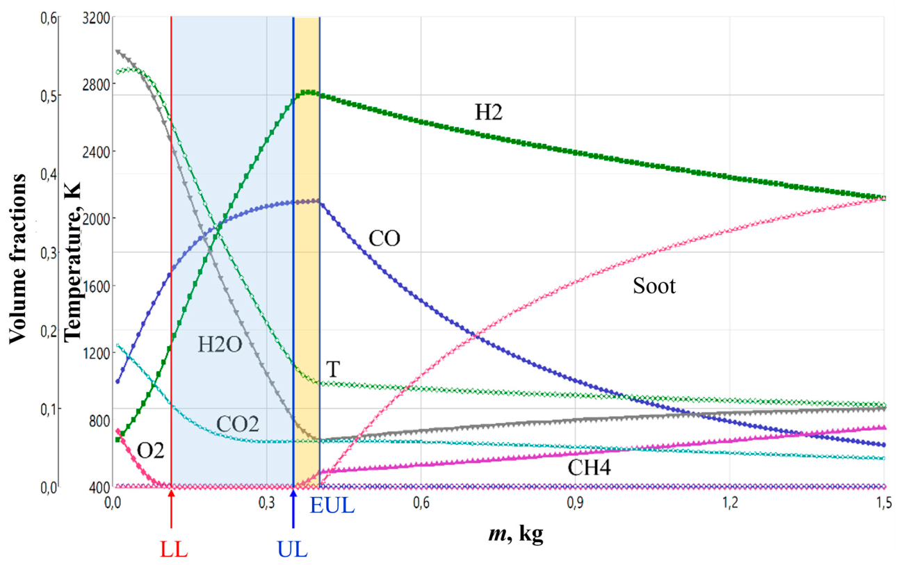
Figure 3.
Calculated temperature and equilibrium composition of chlorohexadecane gasification products as a function of the specific feedstock consumption m (gasification by detonation products of a stoichiometric methane–oxygen mixture without steam addition ( 1, 0).
Figure 3.
Calculated temperature and equilibrium composition of chlorohexadecane gasification products as a function of the specific feedstock consumption m (gasification by detonation products of a stoichiometric methane–oxygen mixture without steam addition ( 1, 0).
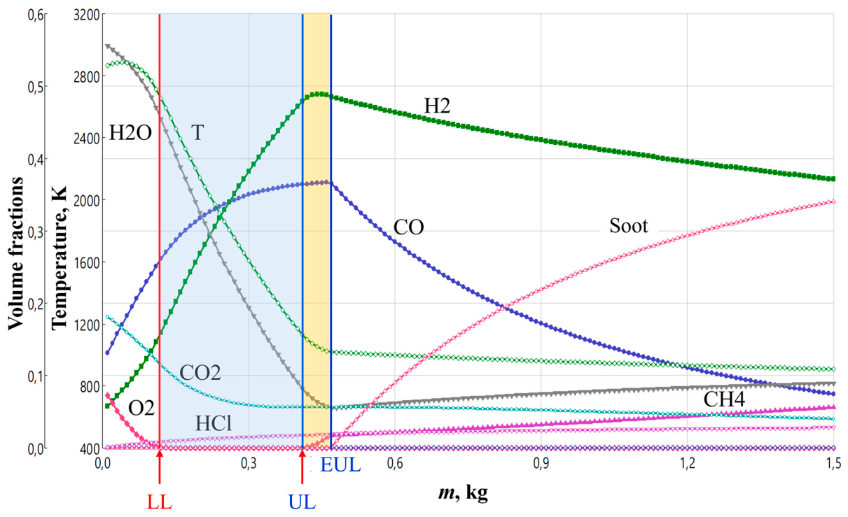

Table 1.
Chemical compounds considered in this work.
| No. | Compound | Chemical formula |
Chlorine mass fraction , % | Note |
|---|---|---|---|---|
| 1 | n-hexadecane | н-С16Н34 | 0 | Validation [34,35,36,37,38,39] + calculation |
| 2 | chlorohexadecane | C16H33Cl | 13.6 | Calculation |
| 3 | chlorohexane | C6H13Cl | 29.4 | Calculation |
| 4 | dichlorobiphenyl | C12H8Cl2 | 31.8 | Calculation |
| 5 | trichlorobiphenyl | C12H7Cl3 | 41.3 | Calculation |
| 6 | tetrachorobiphenyl | C12H6Cl4 | 48.6 | Calculation |
| 7 | chloroform + ethyl acetate | CHCl3 + C4H8O2 | 51.3 | Validation [20] + calculation |
| 8 | vinyl chloride | C2H3Cl | 56.8 | Calculation |
| 9 | methyl chloride | CH₃Cl | 70.0 | Validation [18] + calculation |
| 10 | trichloroethane | C2H3Cl3 | 79.8 | Validation [40,41] + calculation |
| 11 | trichloroethylene | C2HCl3 | 81.0 | Validation [19,40,41] + calculation |
| 12 | perchloroethylene | C2Cl4 | 85.5 | Validation [40,41] + calculation |
Table 2.
Comparison of calculated and experimental equilibrium compositions of syngas obtained from catalytic steam reforming of n-hexadecane at atmospheric pressure.
Table 2.
Comparison of calculated and experimental equilibrium compositions of syngas obtained from catalytic steam reforming of n-hexadecane at atmospheric pressure.
| No. | /C | H2, % | CO, % | CO2, % | CH4, % | N2, % | H2O, % | Soot | Cooling of products |
Ref | ||
|---|---|---|---|---|---|---|---|---|---|---|---|---|
| 1 | 2.7 | 775 | Exp | 71±2 | 19±3 | 11±3 | 2±2 | - | - | - | - | [34] |
| Calc | 70.96 | 17.60 | 11.35 | 0.09 | - | - | No | No | ||||
| 2 | 800 | Exp | 71±3 | 20±5 | 11±4 | 2±2 | - | - | - | - | ||
| Calc | 70.86 | 18.2 | 10.89 | 0.05 | - | - | No | No | ||||
| 3 | 800 | Exp | 70±2 | 20±4 | 11±3 | 1±1 | - | - | - | - | ||
| Calc | 70.86 | 18.2 | 10.89 | 0.05 | - | - | No | No | ||||
| 4 | 3.0 | 550 | Exp | 55±1 | 5±1 | 19±1 | 6±1 | 18±1 | - | - | - | [35] |
| Calc | 52.18 | 4.81 | 16.21 | 7.90 | 18.90 | - | No | No | ||||
| 5 | 650 | Exp | 57±2 | 8±1 | 16±1 | 1±1 | 18±1 | - | - | - | ||
| Calc | 59.65 | 10.36 | 12.86 | 1.18 | 15.95 | - | No | No | ||||
| 6 | 4.0 | 970 K | Exp | 70±1 | 11±1 | 17±2 | 4±2 | - | - | - | - | [36] |
| Calc | 72.52 | 10.86 | 16.42 | 0.20 | - | - | No | No | ||||
| 7 | 4.0 | 923 K | Exp | 21±2 | 3±1 | 4±1 | 1±1 | 41 | 29±2 | Yes | - | [38]; [39] |
| Calc | 25.74 | 3.32 | 6.25 | 0.25 | 41 | 23.44 | No | No | ||||
| 8 | 973 K | Exp | 26±1 | 5±1 | 5±1 | 1±1 | 41 | 24±1 | Yes | - | ||
| Calc | 25.73 | 3.89 | 5.80 | 0.06 | 41 | 23.52 | No | No | ||||
| 9 | 3.0 | 900 | Exp | 70±1 | 15±5 | 16±4 | 0 | - | - | - | Yes | [37] |
| Calc | 70.71 | 18.99 | 10.30 | 0.00 | - | - | No | No | ||||
| 950 | Exp | 70±1 | 14±4 | 14±3 | 3±2 | - | - | - | Yes | |||
| Calc | 70.49 | 19.87 | 9.64 | 0.00 | - | - | No | No |
Table 3.
Comparison of calculated and experimental equilibrium compositions of syngas obtained during the catalytic steam conversion of CHCs at atmospheric pressure.
Table 3.
Comparison of calculated and experimental equilibrium compositions of syngas obtained during the catalytic steam conversion of CHCs at atmospheric pressure.
| No. | Feedstock | /C |
|
H2 % |
CO % |
CO2 % |
H2O % |
HCl % |
CH4 % |
CH3Cl % |
N2 % |
Soot | Cooling of products |
Ref | |
|---|---|---|---|---|---|---|---|---|---|---|---|---|---|---|---|
| 1 | CH3CL | 8.9 | 750 | Exp | 10.2 | 2.4 | 0.9 | 57.8 | 4.5 | 3.2 | 0.1 | 20.5 | Yes | - | [18] |
| Calc | 22.56 | 1.75 | 4.85 | 47.32 | 4.25 | 0.00 | 0.00 | 19.27 | No | No | |||||
| 2 | CHCL3 + C4H8O2 | 2.1 | 750 | Exp | 68.25 | 16.36 | 14.27 | - | - | 1.12 | - | - | Yes | - | [20] |
| Calc | 65.68 | 18.84 | 15.35 | - | - | 0.13 | - | - | No | No | |||||
| 3 | C2HCL3 | 20.0 | 750 | Exp | 36.8 | 1.2 | 24.1 | - | 38.0 | - | - | - | Yes | - | [19] |
| Calc | 36.63 | 1.45 | 23.91 | - | 38.01 | - | - | - | No | No | |||||
| Exp | 59.2 | 1.9 | 38.9 | - | - | - | - | - | Yes | - | |||||
| Calc | 59.09 | 2.34 | 38.57 | - | - | - | - | - | No | No | |||||
| 4 | C2H3CL | 13.2 | 700 | Exp | 39.5 | 7.2 | 16.2 | - | 35.0 | - | 2.1 | - | Yes | - | [40] |
| Calc | 43.29 | 2.13 | 20.56 | - | 34.02 | - | 0.00 | - | No | No | |||||
| 5 | C2HCL3 | 13.0 | 700 | Exp | 33.1 | 4.6 | 21.7 | - | 40.6 | - | - | - | - | - | |
| Calc | 36.37 | 1.87 | 23.59 | - | 38.17 | - | - | - | No | No | |||||
| 6 | C2CL4 | 13.0 | 700 | Exp | 24.7 | 2.8 | 24.6 | - | 47.9 | - | - | - | - | - | |
| Calc | 24.10 | 1.27 | 24.04 | - | 50.59 | - | - | - | No | No |
Table 4.
Parameters of the explosive mixture, equilibrium temperatures, and GA compositions at the inlet of the gasifier reactor.
Table 4.
Parameters of the explosive mixture, equilibrium temperatures, and GA compositions at the inlet of the gasifier reactor.
| No. | Explosive mixture | Content in 1 kg |
, | GA composition, vol.% | |||||||||||
|---|---|---|---|---|---|---|---|---|---|---|---|---|---|---|---|
| CH4 | H2O | O2 | H2 | CO | CO2 | H2O | O2 | CH4 | H | OH | O | ||||
| vol.% | kg | kg | kg | K | |||||||||||
| 1 | 1 | 0 | 0.20 | 0.00 | 0.80 | 2852 | 5 | 12 | 19 | 56 | 8 | 0 | - | - | - |
| 5 | 12 | 17 | 49 | 7 | 0 | 2 | 6 | 2 | |||||||
| 2 | 0.75 | 0 | 0.16 | 0.00 | 0.84 | 2808 | 2 | 6 | 19 | 51 | 22 | 0 | - | - | - |
| 2 | 7 | 18 | 45 | 18 | 0 | 1 | 7 | 2 | |||||||
| 3 | 1.5 | 0 | 0.27 | 0.00 | 0.73 | 2597 | 20 | 24 | 9 | 47 | 0 | 0 | - | - | - |
| 19 | 24 | 9 | 45 | 0 | 0 | 2 | 1 | 0 | |||||||
| 4 | 1 | 20 | 0.17 | 0.14 | 0.68 | 2680 | 4 | 7 | 18 | 66 | 5 | 0 | - | - | - |
| 4 | 7 | 17 | 62 | 4 | 0 | 1 | 4 | 1 | |||||||
| 5 | 1 | 40 | 0.14 | 0.31 | 0.55 | 2440 | 2 | 3 | 17 | 76 | 2 | 0 | - | - | - |
| 2 | 3 | 16 | 75 | 2 | 0 | 0 | 2 | 0 | |||||||
Table 5.
Thermodynamic and integral indicators of the n-hexadecane gasification process at the boundaries of the operating section.
Table 5.
Thermodynamic and integral indicators of the n-hexadecane gasification process at the boundaries of the operating section.
| No. | OP | Composition of gasification products, vol.% | Dry syngas |
DGY | CCE | CGE | NEE | ||||||||||||
|---|---|---|---|---|---|---|---|---|---|---|---|---|---|---|---|---|---|---|---|
| H2 | CO | CO2 | H2O | CH4 | H | OH | O | ||||||||||||
| kg | K | m3 | kg | MJ/m3 | MJ/kg | m3/kg | % | % | % | ||||||||||
| 1 | LL | 0.11 | 2602 | 18 | 27 | 11 | 44 | 0 | - | - | - | 0.74 | 0.68 | 8.60 | 9.33 | 6.70 | 100 | 130 | 70 |
| 0.13 | 2667 | 20 | 29 | 9 | 39 | 0 | 2 | 1 | 0 | 0.87 | 0.72 | 9.14 | 10.97 | 6.68 | 100 | 138 | 78 | ||
| UL | 0.35 | 1134 | 49 | 36 | 6 | 9 | 0 | - | - | - | 2.00 | 1.21 | 9.74 | 16.09 | 5.71 | 100 | 125 | 83 | |
| 0.41 | 1183 | 52 | 39 | 3 | 6 | 0 | 0 | 0 | 0 | 2.28 | 1.31 | 10.05 | 17.42 | 5.55 | 100 | 126 | 87 | ||
| EUL | 0.40 | 1019 | 50 | 36 | 6 | 6 | 2 | - | - | - | 2.16 | 1.30 | 10.14 | 16.83 | 5.40 | 100 | 123 | 83 | |
| 0.45 | 1071 | 53 | 40 | 3 | 3 | 1 | 0 | 0 | 0 | 2.42 | 1.38 | 10.29 | 17.97 | 5.37 | 100 | 124 | 88 | ||
| 2 | LL | 0.21 | 2694 | 21 | 32 | 9 | 38 | 0 | - | - | - | 0.93 | 0.80 | 9.20 | 10.73 | 4.45 | 100 | 92 | 76 |
| 0.21 | 2749 | 21 | 32 | 8 | 35 | 0 | 3 | 1 | 0 | 1.00 | 0.82 | 9.36 | 11.39 | 4.74 | 100 | 100 | 81 | ||
| UL | 0.48 | 1159 | 51 | 40 | 4 | 5 | 0 | - | - | - | 2.33 | 1.38 | 10.04 | 16.94 | 4.86 | 100 | 110 | 86 | |
| 0.53 | 1196 | 53 | 42 | 2 | 3 | 0 | 0 | 0 | 0 | 2.56 | 1.47 | 10.23 | 17.85 | 4.83 | 100 | 111 | 89 | ||
| EUL | 0.52 | 1061 | 51 | 41 | 3 | 4 | 1 | - | - | - | 2.46 | 1.45 | 10.32 | 17.49 | 4.73 | 100 | 110 | 87 | |
| 0.56 | 1115 | 53 | 43 | 2 | 1 | 1 | 0 | 0 | 0 | 2.66 | 1.52 | 10.41 | 18.26 | 4.76 | 100 | 112 | 90 | ||
| 3 | LL* | 0.01 | 2516 | 23 | 25 | 8 | 44 | 0 | - | - | - | 0.73 | 0.59 | 8.99 | 11.05 | - | 100 | - | 74 |
| 0.01 | 2545 | 22 | 25 | 8 | 43 | 0 | 1 | 1 | 0 | 0.75 | 0.60 | 9.08 | 11.39 | - | 100 | - | 76 | ||
| UL | 0.23 | 1127 | 52 | 34 | 5 | 9 | 0 | - | - | - | 1.90 | 1.09 | 9.73 | 16.98 | 8.28 | 100 | 182 | 84 | |
| 0.25 | 1141 | 52 | 35 | 5 | 8 | 0 | 0 | 0 | 0 | 2.00 | 1.13 | 9.84 | 17.45 | 7.99 | 100 | 177 | 86 | ||
| EUL | 0.28 | 1015 | 52 | 34 | 6 | 6 | 2 | - | - | - | 2.06 | 1.18 | 10.18 | 17.73 | 7.35 | 100 | 168 | 85 | |
| 0.30 | 1027 | 53 | 35 | 5 | 5 | 2 | 0 | 0 | 0 | 2.15 | 1.21 | 10.27 | 18.19 | 7.16 | 100 | 166 | 87 | ||
| 4 | LL | 0.08 | 2471 | 15 | 19 | 12 | 54 | 0 | - | - | - | 0.59 | 0.57 | 7.79 | 7.98 | 7.36 | 100 | 129 | 72 |
| 0.09 | 2524 | 16 | 21 | 11 | 50 | 0 | 1 | 1 | 0 | 0.66 | 0.60 | 8.24 | 9.05 | 7.29 | 100 | 135 | 77 | ||
| UL | 0.31 | 1092 | 49 | 30 | 8 | 13 | 0 | - | - | - | 1.83 | 1.11 | 9.34 | 15.45 | 5.91 | 100 | 124 | 84 | |
| 0.34 | 1136 | 50 | 32 | 7 | 11 | 0 | 0 | 0 | 0 | 1.97 | 1.16 | 9.57 | 16.29 | 5.78 | 100 | 125 | 87 | ||
| EUL | 0.37 | 981 | 50 | 30 | 9 | 9 | 2 | - | - | - | 2.02 | 1.22 | 9.90 | 16.35 | 5.45 | 100 | 121 | 85 | |
| 0.40 | 1003 | 51 | 32 | 7 | 8 | 2 | 0 | 0 | 0 | 2.17 | 1.27 | 10.02 | 17.10 | 5.42 | 100 | 122 | 88 | ||
| 5 | LL | 0.04 | 2338 | 9 | 9 | 14 | 68 | 0 | - | - | - | 0.39 | 0.44 | 5.93 | 5.21 | 9.63 | 100 | 129 | 73 |
| 0.04 | 2375 | 8 | 10 | 14 | 67 | 0 | 0 | 1 | 0 | 0.40 | 0.44 | 6.08 | 5.48 | 9.95 | 100 | 136 | 75 | ||
| UL | 0.25 | 1081 | 46 | 22 | 11 | 21 | 0 | - | - | - | 1.55 | 0.95 | 8.81 | 14.44 | 6.21 | 100 | 123 | 86 | |
| 0.27 | 1066 | 48 | 23 | 10 | 19 | 0 | 0 | 0 | 0 | 1.65 | 0.99 | 8.93 | 14.93 | 6.13 | 100 | 123 | 88 | ||
| EUL | 0.34 | 937 | 48 | 22 | 12 | 14 | 4 | - | - | - | 1.83 | 1.12 | 9.76 | 15.88 | 5.38 | 100 | 118 | 88 | |
| 0.35 | 945 | 49 | 23 | 11 | 13 | 4 | 0 | 0 | 0 | 1.89 | 1.14 | 9.78 | 16.17 | 5.40 | 100 | 119 | 89 | ||
* This case virtually corresponds to the autothermal steam – carbon dioxide reforming of methane during the detonation of a fuel-rich methane–oxygen mixture.
Table 6.
Thermodynamic and integral indicators of the gasification process of various CHCs at the boundaries of the operating section.
Table 6.
Thermodynamic and integral indicators of the gasification process of various CHCs at the boundaries of the operating section.
| Waste | OP | Composition of gasification products, vol % | Dry gas | DGY | CCE | CGE | NEE | ||||||||||||||
|---|---|---|---|---|---|---|---|---|---|---|---|---|---|---|---|---|---|---|---|---|---|
| H2O | HCl | H2 | CO | CO2 | CH4 | H | OH | O | |||||||||||||
| % | kg | K | m3 | kg | MJ/m3 | MJ/kg | nm3/kg | % | % | % | |||||||||||
| C16H33Cl | 14 | LL | 0.13 | 2590 | 44 | 1 | 17 | 27 | 11 | 0 | - | - | - | 0.74 | 0.69 | 8.60 | 9.30 | 5.71 | 100 | 129 | 70 |
| 0.15 | 2674 | 39 | 1 | 19 | 29 | 9 | 0 | 2 | 1 | 0 | 0.86 | 0.73 | 9.10 | 10.78 | 5.74 | 100 | 138 | 78 | |||
| UL | 0.41 | 1132 | 8 | 2 | 48 | 36 | 6 | 0 | - | - | - | 1.99 | 1.22 | 9.74 | 15.88 | 4.85 | 100 | 125 | 82 | ||
| 0.48 | 1188 | 5 | 2 | 50 | 40 | 3 | 0 | 0 | 0 | 0 | 2.26 | 1.32 | 10.07 | 17.25 | 4.71 | 100 | 125 | 87 | |||
| EUL | 0.46 | 1026 | 6 | 2 | 48 | 37 | 6 | 1 | - | - | - | 2.13 | 1.30 | 10.09 | 16.58 | 4.64 | 100 | 124 | 83 | ||
| 0.53 | 1071 | 3 | 2 | 51 | 40 | 3 | 1 | 0 | 0 | 0 | 2.41 | 1.40 | 10.35 | 17.84 | 4.55 | 100 | 124 | 88 | |||
| C6H13Cl | 29 | LL | 0.15 | 2630 | 45 | 2 | 16 | 26 | 11 | 0 | - | - | - | 0.71 | 0.67 | 8.43 | 8.90 | 4.74 | 100 | 129 | 70 |
| 0.18 | 2676 | 39 | 3 | 18 | 28 | 9 | 0 | 2 | 1 | 0 | 0.85 | 0.72 | 9.04 | 10.61 | 4.70 | 100 | 138 | 77 | |||
| UL | 0.51 | 1121 | 8 | 5 | 46 | 35 | 6 | 0 | - | - | - | 2.00 | 1.23 | 9.74 | 15.94 | 3.93 | 100 | 124 | 82 | ||
| 0.60 | 1159 | 5 | 5 | 49 | 38 | 3 | 0 | 0 | 0 | 0 | 2.29 | 1.33 | 10.08 | 17.31 | 3.81 | 100 | 125 | 87 | |||
| EUL | 0.57 | 1024 | 6 | 5 | 47 | 36 | 5 | 1 | - | - | - | 2.14 | 1.30 | 10.12 | 16.62 | 3.75 | 100 | 123 | 83 | ||
| 0.65 | 1071 | 3 | 5 | 49 | 39 | 3 | 1 | 0 | 0 | 0 | 2.40 | 1.39 | 10.32 | 17.80 | 3.70 | 100 | 124 | 88 | |||
| C12H8Cl2 | 32 | LL | 0.21 | 2638 | 37 | 4 | 15 | 32 | 12 | 0 | - | - | - | 0.79 | 0.79 | 8.64 | 8.71 | 3.78 | 100 | 126 | 70 |
| 0.24 | 2717 | 32 | 4 | 17 | 34 | 10 | 0 | 2 | 1 | 0 | 0.92 | 0.84 | 9.13 | 9.98 | 3.81 | 100 | 135 | 77 | |||
| UL | 0.64 | 1179 | 2 | 7 | 37 | 52 | 2 | 0 | - | - | - | 1.96 | 1.40 | 10.43 | 14.56 | 3.06 | 100 | 123 | 82 | ||
| 0.69 | 1396 | 0 | 7 | 38 | 55 | 0 | 0 | 0 | 0 | 0 | 2.07 | 1.46 | 10.66 | 15.14 | 3.00 | 100 | 124 | 86 | |||
| EUL | 0.65 | 1156 | 1 | 7 | 37 | 53 | 2 | 0 | - | - | - | 1.98 | 1.42 | 10.52 | 14.69 | 3.04 | 100 | 124 | 82 | ||
| 0.69 | 1396 | 0 | 7 | 38 | 55 | 0 | 0 | 0 | 0 | 0 | 2.07 | 1.46 | 10.66 | 15.14 | 3.00 | 100 | 124 | 86 | |||
| C12H7Cl3 | 41 | LL | 0.25 | 2631 | 35 | 5 | 16 | 32 | 12 | 0 | - | - | - | 0.79 | 0.80 | 8.58 | 8.53 | 3.18 | 100 | 126 | 70 |
| 0.29 | 2707 | 30 | 6 | 16 | 35 | 10 | 0 | 2 | 1 | 0 | 0.92 | 0.85 | 9.13 | 9.84 | 3.17 | 100 | 134 | 77 | |||
| UL | 0.75 | 1198 | 1 | 10 | 34 | 53 | 2 | 0 | - | - | - | 1.91 | 1.41 | 10.52 | 14.24 | 2.54 | 100 | 123 | 82 | ||
| 0.80 | 1437 | 0 | 10 | 35 | 55 | 0 | 0 | 0 | 0 | 0 | 2.00 | 1.46 | 10.71 | 14.72 | 2.50 | 100 | 124 | 86 | |||
| EUL | 0.77 | 1160 | 1 | 10 | 34 | 54 | 1 | 0 | - | - | - | 1.94 | 1.43 | 10.63 | 14.41 | 2.51 | 100 | 123 | 82 | ||
| 0.80 | 1437 | 0 | 10 | 35 | 55 | 0 | 0 | 0 | 0 | 0 | 2.00 | 1.46 | 10.71 | 14.72 | 2.50 | 100 | 124 | 86 | |||
| C12H6Cl4 | 49 | LL | 0.29 | 2638 | 34 | 7 | 14 | 32 | 13 | 0 | - | - | - | 0.79 | 0.81 | 8.53 | 8.32 | 2.72 | 100 | 125 | 70 |
| 0.34 | 2706 | 29 | 8 | 15 | 35 | 10 | 0 | 2 | 1 | 0 | 0.92 | 0.87 | 9.09 | 9.63 | 2.71 | 100 | 133 | 77 | |||
| UL | 0.88 | 1205 | 1 | 14 | 30 | 54 | 1 | 0 | - | - | - | 1.88 | 1.43 | 10.63 | 14.02 | 2.14 | 100 | 123 | 82 | ||
| 0.91 | 1499 | 0 | 14 | 31 | 55 | 0 | 0 | 0 | 0 | 0 | 1.93 | 1.45 | 10.76 | 14.30 | 2.12 | 100 | 123 | 86 | |||
| EUL | 0.88 | 1205 | 1 | 14 | 30 | 54 | 1 | 0 | - | - | - | 1.88 | 1.43 | 10.63 | 14.02 | 2.14 | 100 | 123 | 82 | ||
| 0.91 | 1499 | 0 | 14 | 31 | 55 | 0 | 0 | 0 | 0 | 0 | 1.93 | 1.45 | 10.76 | 14.30 | 2.12 | 100 | 123 | 86 | |||
| CHCl3 + C4H8O2 | 7 | LL | 0.20 | 2593 | 47 | 1 | 14 | 25 | 13 | 0 | - | - | - | 0.71 | 0.72 | 7.99 | 7.86 | 3.55 | 100 | 128 | 69 |
| 0.24 | 2646 | 42 | 1 | 16 | 27 | 11 | 0 | 2 | 1 | 0 | 0.84 | 0.78 | 8.61 | 9.33 | 3.50 | 100 | 136 | 77 | |||
| UL | 0.72 | 1089 | 12 | 1 | 44 | 33 | 10 | 0 | - | - | - | 2.12 | 1.45 | 9.20 | 13.47 | 2.95 | 100 | 122 | 82 | ||
| 0.85 | 1112 | 10 | 1 | 45 | 36 | 8 | 0 | 0 | 0 | 0 | 2.43 | 1.60 | 9.55 | 14.51 | 2.85 | 100 | 123 | 87 | |||
| EUL | 0.85 | 978 | 9 | 2 | 43 | 33 | 11 | 2 | - | - | - | 2.35 | 1.62 | 9.62 | 13.98 | 2.77 | 100 | 120 | 84 | ||
| 0.98 | 999 | 7 | 2 | 45 | 36 | 8 | 2 | 0 | 0 | 0 | 2.66 | 1.76 | 9.87 | 14.91 | 2.71 | 100 | 120 | 88 | |||
| C2H3Cl | 57 | LL | 0.33 | 2666 | 36 | 9 | 16 | 29 | 10 | 0 | - | - | - | 0.81 | 0.76 | 8.81 | 9.36 | 2.44 | 100 | 117 | 72 |
| 0.37 | 2729 | 31 | 9 | 18 | 30 | 8 | 0 | 3 | 1 | 0 | 0.93 | 0.80 | 9.23 | 10.62 | 2.50 | 100 | 126 | 78 | |||
| UL | 1.16 | 1307 | 0 | 17 | 39 | 44 | 0 | 0 | - | - | - | 2.30 | 1.48 | 10.54 | 16.41 | 1.98 | 100 | 114 | 85 | ||
| 1.17 | 1581 | 0 | 17 | 39 | 44 | 0 | 0 | 0 | 0 | 0 | 2.32 | 1.49 | 10.57 | 16.51 | 1.98 | 100 | 114 | 88 | |||
| EUL | 1.16 | 1307 | 0 | 17 | 39 | 44 | 0 | 0 | - | - | - | 2.30 | 1.48 | 10.54 | 16.41 | 1.98 | 100 | 114 | 85 | ||
| 1.17 | 1581 | 0 | 17 | 39 | 44 | 0 | 0 | 0 | 0 | 0 | 2.32 | 1.49 | 10.57 | 16.51 | 1.98 | 100 | 114 | 88 | |||
| CH3Cl | 70 | LL | 0.35 | 2597 | 41 | 13 | 13 | 22 | 11 | 0 | - | - | - | 0.68 | 0.66 | 8.23 | 8.40 | 1.93 | 100 | 125 | 69 |
| 0.41 | 2660 | 36 | 13 | 15 | 24 | 9 | 0 | 2 | 1 | 0 | 0.79 | 0.70 | 8.81 | 9.97 | 1.94 | 100 | 134 | 77 | |||
| UL | 1.35 | 1104 | 5 | 23 | 39 | 29 | 4 | 0 | - | - | - | 2.09 | 1.26 | 9.82 | 16.29 | 1.55 | 100 | 120 | 83 | ||
| 1.58 | 1141 | 3 | 24 | 40 | 31 | 2 | 0 | 0 | 0 | 0 | 2.38 | 1.37 | 10.16 | 17.65 | 1.51 | 100 | 120 | 88 | |||
| EUL | 1.51 | 1021 | 4 | 23 | 39 | 29 | 4 | 1 | - | - | - | 2.24 | 1.34 | 10.18 | 17.02 | 1.48 | 100 | 119 | 84 | ||
| 1.70 | 1073 | 2 | 24 | 40 | 31 | 2 | 1 | 0 | 0 | 0 | 2.49 | 1.43 | 10.37 | 18.14 | 1.47 | 100 | 120 | 89 | |||
| C2H3Cl3 | 80 | LL | 0.64 | 2576 | 32 | 23 | 9 | 23 | 13 | 0 | - | - | - | 0.68 | 0.76 | 7.66 | 6.87 | 1.06 | 100 | 118 | 67 |
| 0.77 | 2637 | 27 | 25 | 10 | 25 | 11 | 0 | 1 | 1 | 0 | 0.80 | 0.82 | 8.39 | 8.20 | 1.03 | 100 | 126 | 75 | |||
| UL | 2.40 | 1136 | 1 | 42 | 19 | 37 | 1 | 0 | - | - | - | 1.80 | 1.42 | 10.71 | 13.56 | 0.75 | 100 | 116 | 81 | ||
| 2.49 | 1334 | 0 | 43 | 19 | 38 | 0 | 0 | 0 | 0 | 0 | 1.85 | 1.45 | 10.80 | 13.83 | 0.74 | 100 | 116 | 84 | |||
| EUL | 2.40 | 1136 | 1 | 42 | 19 | 37 | 1 | 0 | - | - | - | 1.80 | 1.42 | 10.71 | 13.56 | 0.75 | 100 | 116 | 81 | ||
| 2.49 | 1334 | 0 | 43 | 19 | 38 | 0 | 0 | 0 | 0 | 0 | 1.85 | 1.45 | 10.80 | 13.83 | 0.74 | 100 | 116 | 84 | |||
| C2HCl3* | 81 | LL | 1.03 | 2624 | 19 | 34 | 6 | 28 | 13 | 0 | - | - | - | 0.81 | 0.94 | 8.03 | 6.92 | 0.79 | 100 | - | 108 |
| 1.22 | 2691 | 14 | 37 | 6 | 31 | 10 | 0 | 1 | 1 | 0 | 0.93 | 1.02 | 8.74 | 7.99 | 0.76 | 100 | - | 127 | |||
| UL | 2.46 | 1824 | 0 | 50 | 6 | 44 | 0 | 0 | - | - | - | 1.39 | 1.41 | 11.21 | 11.05 | 0.57 | 100 | - | 187 | ||
| 2.46 | 2093 | 0 | 50 | 6 | 44 | 0 | 0 | 0 | 0 | 0 | 1.39 | 1.41 | 11.20 | 11.06 | 0.57 | 100 | - | 195 | |||
| EUL | 2.46 | 1824 | 0 | 50 | 6 | 44 | 0 | 0 | - | - | - | 1.39 | 1.41 | 11.21 | 11.05 | 0.57 | 100 | - | 187 | ||
| 2.46 | 2093 | 0 | 50 | 6 | 44 | 0 | 0 | 0 | 0 | 0 | 1.39 | 1.41 | 11.20 | 11.06 | 0.57 | 100 | - | 195 | |||
| C2Cl4** | 86 | LL | 1.94 | 2594 | 2 | 54 | 1 | 28 | 15 | 0 | - | - | - | 0.91 | 1.22 | 7.38 | 5.49 | 0.47 | 100 | - | 113 |
| 2.21 | 2676 | 0 | 54 | 0 | 33 | 11 | 0 | 0 | 0 | 0 | 1.03 | 1.40 | 7.97 | 5.85 | 0.47 | 100 | - | 132 | |||
| UL | 3.11 | 1616 | 0 | 45 | 0 | 44 | 0 | 0 | - | - | - | 1.55 | 2.28 | 9.12 | 6.18 | 0.50 | 100 | - | 167 | ||
| 3.11 | 1890 | 0 | 45 | 0 | 44 | 0 | 0 | 0 | 0 | 0 | 1.55 | 2.28 | 9.13 | 6.18 | 0.50 | 100 | - | 175 | |||
| EUL | 3.11 | 1616 | 0 | 45 | 0 | 44 | 0 | 0 | - | - | - | 1.55 | 2.28 | 9.12 | 6.18 | 0.50 | 100 | - | 167 | ||
| 3.11 | 1890 | 0 | 45 | 0 | 44 | 0 | 0 | 0 | 0 | 0 | 1.55 | 2.28 | 9.13 | 6.18 | 0.50 | 100 | - | 175 | |||
* For С2НCl3 и C2Cl4, the LHV is assumed to be 0. Therefore, the NEE exceeds 100%. ** Cl2 is present in the C2Cl4 gasification products in amounts ranging from 0.2 to 11 vol.%. The parameters of the process and gasification products are calculated taking Cl2 into account. Phosgene is also present in the products in amounts up to 0.0014 vol.%.
Table 7.
Characteristics of CHC gasification products at the specific feedstock consumption corresponding to the complete dissolution of HCl in the steam condensate at 293 K and 0.1 MPa.
Table 7.
Characteristics of CHC gasification products at the specific feedstock consumption corresponding to the complete dissolution of HCl in the steam condensate at 293 K and 0.1 MPa.
| Feed | Composition of gasification products, vol % | Dry gas | DGY | CCE | CGE | NEE | |||||||||||||||
|---|---|---|---|---|---|---|---|---|---|---|---|---|---|---|---|---|---|---|---|---|---|
| H2O | HCl | H2 | CO | CO2 | CH4 | H | OH | O | |||||||||||||
| % | kg | K | nm3 | kg | MJ/m3 | MJ/kg | nm3/kg | % | % | % | |||||||||||
| C16H33Cl | 14 | 0.46 | 1026 | 6 | 2 | 48 | 37 | 6 | 1 | - | - | - | 0.33 | 2.13 | 1.30 | 10.09 | 16.58 | 4,64 | 100 | 124 | 83 |
| 0.47 | 1225 | 6 | 2 | 50 | 39 | 3 | 0 | 0 | 0 | 0 | 0.32 | 2.22 | 1.30 | 10.06 | 17.14 | 4,72 | 100 | 125 | 87 | ||
| C6H13Cl | 29 | 0.45 | 1309 | 12 | 4 | 43 | 35 | 6 | 0 | - | - | - | 0.36 | 1.78 | 1.13 | 9.74 | 15.40 | 3,96 | 100 | 125 | 81 |
| 0.47 | 1573 | 12 | 4 | 43 | 37 | 4 | 0 | 0 | 0 | 0 | 0.36 | 1.82 | 1.13 | 9.98 | 16.05 | 3,87 | 100 | 125 | 86 | ||
| C12H8Cl2 | 32 | 0.42 | 1848 | 15 | 5 | 30 | 44 | 6 | 0 | - | - | - | 0.35 | 1.36 | 1.09 | 9.89 | 12.38 | 3,25 | 100 | 124 | 78 |
| 0.43 | 2190 | 16 | 5 | 28 | 46 | 5 | 0 | 0 | 0 | 0 | 0.35 | 1.38 | 1.09 | 10.07 | 12.71 | 3,21 | 100 | 125 | 83 | ||
| C12H7Cl3 | 41 | 0.41 | 2105 | 21 | 7 | 23 | 41 | 8 | 0 | - | - | - | 0.35 | 1.15 | 0.99 | 9.62 | 11.12 | 2,80 | 100 | 124 | 76 |
| 0.41 | 2447 | 21 | 7 | 22 | 42 | 7 | 0 | 1 | 0 | 0 | 0.35 | 1.15 | 0.99 | 9.78 | 11.39 | 2,80 | 100 | 126 | 80 | ||
| C12H6Cl4 | 49 | 0.40 | 2323 | 25 | 9 | 19 | 38 | 9 | 0 | - | - | - | 0.36 | 0.99 | 0.92 | 9.27 | 9.95 | 2,48 | 100 | 124 | 74 |
| 0.40 | 2607 | 25 | 9 | 16 | 38 | 9 | 0 | 2 | 1 | 0 | 0.36 | 1.01 | 0.92 | 9.44 | 10.32 | 2,53 | 100 | 129 | 78 | ||
| CHCl3 + C4H8O2 | 7 | 0.85 | 978 | 9 | 2 | 43 | 33 | 11 | 2 | - | - | - | 0.17 | 2.35 | 1.62 | 9.62 | 13.98 | 2,77 | 100 | 120 | 84 |
| 0.98 | 999 | 7 | 2 | 45 | 36 | 8 | 2 | 0 | 0 | 0 | 0.22 | 2.66 | 1.76 | 9.87 | 14.91 | 2,71 | 100 | 120 | 88 | ||
| C2H3Cl | 57 | 0.42 | 2465 | 29 | 10 | 21 | 32 | 8 | 0 | - | - | - | 0.35 | 0.96 | 0.83 | 9.30 | 10.72 | 2,29 | 100 | 116 | 74 |
| 0.41 | 2681 | 29 | 10 | 18 | 32 | 8 | 0 | 2 | 1 | 0 | 0.35 | 0.98 | 0.83 | 9.43 | 11.11 | 2,40 | 100 | 123 | 79 | ||
| CH3Cl | 70 | 0.42 | 2443 | 37 | 13 | 17 | 24 | 9 | 0 | - | - | - | 0.36 | 0.76 | 0.70 | 8.66 | 9.50 | 1,82 | 100 | 124 | 71 |
| 0.41 | 2660 | 36 | 13 | 15 | 24 | 9 | 0 | 2 | 1 | 0 | 0.36 | 0.79 | 0.70 | 8.81 | 9.97 | 1,94 | 100 | 134 | 77 | ||
| C2H3Cl3* | 80 | 0.34 | 2807 | 41 | 15 | 7 | 18 | 17 | 0 | - | - | - | 0.35 | 0.55 | 0.67 | 6.14 | 5.00 | 1,60 | 100 | 147 | 62 |
| 0.32 | 2827 | 38 | 14 | 6 | 18 | 15 | 0 | 2 | 4 | 1 | 0.36 | 0.63 | 0.70 | 6.61 | 5.99 | 1,98 | 100 | 194 | 69 | ||
| C2HCl3* | 81 | 0.31 | 2863 | 41 | 14 | 6 | 17 | 18 | 0 | - | - | - | 0.35 | 0.54 | 0.69 | 5.56 | 4.37 | 1,75 | 100 | - | 71 |
| 0.28 | 2860 | 37 | 13 | 5 | 17 | 16 | 0 | 2 | 5 | 1 | 0.35 | 0.63 | 0.72 | 6.07 | 5.35 | 2,25 | 100 | - | 78 | ||
| C2Cl4* | 86 | 0.29 | 2849 | 40 | 15 | 5 | 15 | 19 | 0 | - | - | - | 0.36 | 0.52 | 0.68 | 4.75 | 3.58 | 1,78 | 100 | - | 64 |
| 0.26 | 2852 | 38 | 13 | 4 | 15 | 17 | 0 | 2 | 5 | 1 | 0.35 | 0.60 | 0.71 | 5.43 | 4.64 | 2,32 | 100 | - | 71 | ||
* The parameters of the process and gasification products are calculated taking residual oxygen (from 2 to 6 vol.%) into account.
Disclaimer/Publisher’s Note: The statements, opinions and data contained in all publications are solely those of the individual author(s) and contributor(s) and not of MDPI and/or the editor(s). MDPI and/or the editor(s) disclaim responsibility for any injury to people or property resulting from any ideas, methods, instructions or products referred to in the content. |
© 2026 by the authors. Licensee MDPI, Basel, Switzerland. This article is an open access article distributed under the terms and conditions of the Creative Commons Attribution (CC BY) license (http://creativecommons.org/licenses/by/4.0/).
Copyright: This open access article is published under a Creative Commons CC BY 4.0 license, which permit the free download, distribution, and reuse, provided that the author and preprint are cited in any reuse.


