
Submitted:
11 May 2026
Posted:
12 May 2026
You are already at the latest version
Abstract
The accelerating accumulation of atmospheric carbon dioxide (CO₂) from fossil fuel combustion represents one of the foremost environmental challenges of the twenty-first century. This paper presents the design, theoretical basis, and experimental framework of a novel artificial photosynthesis system capable of capturing CO₂ from combustion flue gases and converting it into oxygen (O₂) and energy-rich compounds, directly mimicking the biochemical process performed by trees. The proposed system integrates a sodium carbonate (Na₂CO₃) absorption tower for CO₂ capture, a thermal desorption unit for solvent regeneration, and a cobalt oxide-catalyzed photosynthetic reactor for CO₂-to-O₂ conversion. System performance is quantified using non-dispersive infrared (NDIR) sensors for CO₂ measurement and electrochemical oxygen sensors for O₂ detection. Stoichiometric analysis indicates that 1 kg of captured CO₂ yields approximately 0.73 kg of O₂, and national-scale deployment projections suggest energy savings of approximately $200 billion per year by 2030 alongside a potential reduction of 302,600 million metric tons of CO₂ emissions. Comparative analysis with existing decarbonization approaches—including carbon capture and storage (CCS), hydrogen production, and enhanced oil recovery (EOR)—demonstrates that artificial photosynthesis offers a fundamentally superior outcome by permanently transforming CO₂ into life-sustaining O₂ rather than merely sequestering or displacing it. This work establishes a laboratory-scale proof of concept and a systematic experimental roadmap for scaling the technology to industrial application.
Keywords:
artificial photosynthesis
; carbon dioxide capture
; CO₂ conversion
; sodium carbonate absorption
; cobalt oxide catalyst
; oxygen production
; carbon capture utilization
; decarbonization
1. Introduction
The combustion of fossil fuels remains the dominant driver of global carbon dioxide (CO₂) emissions, which have approximately doubled over the fifty-year period from 1971 to 2021 [5]. While international agreements such as the Paris Accord and successive United Nations Climate Change Conferences have set ambitious decarbonization targets, fossil fuels continue to supply the majority of global primary energy and are projected to remain a significant component of the energy mix through 2050, given the limitations of current renewable energy technologies in meeting large-scale, continuous baseload demand [4].
Rather than approaching fossil fuel combustion as an inherently irredeemable process, this paper proposes a paradigm shift: treating CO₂ not as a pollutant to be suppressed or buried, but as a feedstock to be valorized. Nature has provided a compelling precedent for this approach in the form of photosynthesis. Through this biochemical process, trees and other photosynthetic organisms continuously absorb CO₂ from the atmosphere, using solar energy to convert it into glucose and oxygen. According to the United States Department of Agriculture (USDA), a single mature tree absorbs approximately 48 pounds (21.8 kg) of CO₂ per year, and a one-hectare plantation of 1,000 trees sequesters approximately 22 tonnes of CO₂ annually [1]. Artificial photosynthesis systems, which replicate this chemistry using engineered materials and catalysts, have been shown to achieve CO₂ capture rates approximately 1,000 times greater than those of biological trees per unit area [2].
This paper describes the design, theoretical framework, and experimental methodology of a laboratory-scale artificial photosynthesis system that captures CO₂ from combustion flue gas and converts it into oxygen. The system employs sodium carbonate (Na₂CO₃) as a non-toxic, low-cost absorbent solvent; cobalt oxide (Co₃O₄) as a stable, earth-abundant photocatalyst; and solar thermal energy for the endothermic photosynthetic reaction. The paper is structured as follows: Section 2 reviews the biochemical and chemical principles underpinning the system; Section 3 presents the system design and experimental methodology; Section 4 discusses instrumentation and measurement; Section 5 reports performance analysis and national-scale impact projections; Section 6 compares the proposed approach with existing decarbonization methods; and Section 7 presents conclusions and future directions.
2. Background and Theoretical Foundations
2.1. Natural Photosynthesis Mechanism
The photosynthesis process occurs within chloroplasts, subcellular organelles containing thylakoid membranes rich in chlorophyll — the green pigment responsible for light absorption. When solar radiation strikes the thylakoid membrane, chlorophyll molecules are excited, releasing high-energy electrons. These electrons drive a cascade of redox reactions collectively known as the light reactions, during which adenosine diphosphate (ADP) is phosphorylated to adenosine triphosphate (ATP) and nicotinamide adenine dinucleotide phosphate (NADP⁺) is reduced to NADPH:
2H₂O + ADP + NADP⁺ → O₂ + ATP + NADPH
The ATP and NADPH produced in the light reactions then power the Calvin cycle (dark reactions), in which CO₂ is fixed and reduced to glucose:
ATP + NADPH + CO₂ → C₆H₁₂O₆ (glucose)
The net photosynthesis reaction, combining both stages, is expressed as:
6CO₂ + 6H₂O + Q (solar energy) → C₆H₁₂O₆ + 6O₂
2.2. Artificial Photosynthesis Principles
Artificial photosynthesis replicates the essential function of Equation (3) using engineered semiconductor photocatalysts and redox mediators in place of biological chlorophyll and enzymes. The two critical half-reactions are the oxidative water-splitting reaction at the anode, which generates oxygen, protons, and electrons:
and the reductive reaction at the cathode, where protons are reduced to hydrogen fuel:
2H₂O → 4H⁺ + O₂ + 4e⁻ (Anode)
2H⁺ + 2e⁻ → H₂ (Cathode)
Water splitting is thermodynamically non-spontaneous under standard conditions, requiring approximately 280 kJ/mol H₂O [internal calculation]. The presence of an appropriate photocatalyst substantially lowers the activation energy barrier, enabling the reaction to proceed under solar illumination. Key catalyst systems investigated in the literature include manganese-based complexes (which mimic the oxygen-evolving complex of Photosystem II), dye-sensitized titanium dioxide (TiO₂) nanoparticles, and cobalt oxide (Co₃O₄). Among these, cobalt oxide has emerged as the most promising candidate for large-scale application owing to its chemical stability, high catalytic activity, abundance in the Earth's crust, and compatibility with solid-state reactor configurations.
2.3. CO₂ Capture Chemistry
2.3.1. Amine-Based Solvents
Amine compounds have been extensively studied as CO₂ absorbents. Primary amines (e.g., monoethanolamine, MEA) and secondary amines (e.g., diethanolamine, DEA) react rapidly with CO₂ to form stable carbamate species:
R-NH₂ + CO₂ → RNHCOO⁻ + H⁺
While primary and secondary amines offer high reaction rates and good absorption capacity, they suffer from significant drawbacks including high energy requirements for solvent regeneration, equipment corrosion necessitating inhibitors and resistant materials, and degradation in the presence of oxygen, SOx, and other flue gas impurities (HCl, HF, Hg) [6]. Tertiary amines (e.g., methyldiethanolamine, MDEA) avoid carbamate formation but exhibit lower CO₂ absorption rates due to the absence of an N–H bond, reacting instead via base-catalyzed hydration to form bicarbonate ions [6].
2.3.2. Sodium Carbonate — Selected Absorbent
To overcome the limitations of amine solvents, this work selects sodium carbonate (Na₂CO₃) as the CO₂ absorbent. The absorption reaction is reversible and proceeds as follows:
CO₂ + Na₂CO₃ + H₂O ⇌ 2NaHCO₃
The forward reaction (absorption) is exothermic (ΔH ≈ −32.4 kcal/mol CO₂), and the optimal operating temperature for the absorption unit has been identified at approximately 70°C based on the phase diagram of the Na₂CO₃–NaHCO₃–H₂O system [8]. Desorption (regeneration) is achieved by heating the CO₂-rich sodium bicarbonate solution above 80°C:
2NaHCO₃ → Na₂CO₃ + CO₂ + H₂O (T > 80°C)
Sodium carbonate also reacts with acidic flue gas impurities, providing simultaneous desulfurization and dechlorination:
Na₂CO₃(s) + 2HCl → 2NaCl(s) + H₂O(g) + CO₂(g)
Na₂CO₃(s) + SO₂(g) + ½O₂(g) → Na₂SO₄(s) + CO₂(g)
Key advantages of Na₂CO₃ relative to amine solvents include low cost, low corrosivity, non-toxicity, non-volatility, and straightforward thermal regeneration without the high energy penalties associated with amine stripping. These characteristics are well-documented in the literature [20,21,22,23]. The solubility of Na₂CO₃ in water at 35°C is approximately 50 g/100 mL H₂O, providing a high absorption capacity per unit volume of solvent.
3. System Design and Experimental Methodology
3.1. Case Study Site
The system is designed and evaluated in the context of a laboratory facility at the University of Louisiana at Lafayette (latitude 30.2°N), where the Artificial Photosynthesis Research Laboratory is under development. The laboratory is equipped with computing infrastructure provided by the School of Computer Science and data acquisition systems from the Department of Petroleum Engineering, enabling real-time monitoring and long-term data archiving.
3.2. Overall Process Description
The integrated system comprises three primary functional units: (1) a CO₂ capture unit based on Na₂CO₃ absorption; (2) a thermal desorption unit for CO₂ recovery and solvent regeneration; and (3) an artificial photosynthesis reactor for CO₂-to-O₂ conversion. The process flow is illustrated in Figure 1 (schematic to be inserted), and the detailed system layout is shown in Figure 2.
Atmospheric air or combustion flue gas is drawn into the system by an air suction unit and fed to the base of the absorption tower. Within the tower, the rising gas stream contacts a descending Na₂CO₃ solution (concentration approximately 50 g/100 mL), forming sodium bicarbonate (NaHCO₃) according to Equation (7). The CO₂-rich NaHCO₃ solution is withdrawn from the bottom of the absorption tower and passed through a plate heat exchanger, where it is preheated by the hot lean solvent returning from the desorption unit. The preheated solution then enters the desorption unit, where it is heated above 80°C to release concentrated CO₂ gas (Equation 8) and regenerate the Na₂CO₃ solvent. The regenerated lean solvent is recirculated to the absorption tower after passing through the heat exchanger, minimizing thermal energy consumption. The liberated CO₂ stream is directed to the photosynthetic reactor.
3.3. Photosynthesis Reactor
Within the fluidized bed reactor, CO₂ and water undergo artificial photosynthesis in the presence of cobalt oxide (Co₃O₄) catalyst and thermal energy supplied by a solar thermal storage system:
6CO₂ + 6H₂O + Q (solar heat) → C₆H₁₂O₆ + 6O₂ [Co₃O₄ catalyst]
Water is supplied to the reactor via a peristaltic pump. The reactor operating temperature is maintained at 70°C, consistent with the thermodynamic requirements of the cobalt oxide-catalyzed system. A thermal energy storage unit employing hot silicon technology stores solar energy during periods of peak irradiance for deployment during periods of low solar intensity, ensuring continuous reactor operation independent of instantaneous solar conditions.
Cobalt oxide was selected as the catalyst based on its demonstrated stability under repeated reaction cycles, high intrinsic catalytic activity for water oxidation, availability in large crustal reserves, and compatibility with solid-state fluidized bed operation — avoiding the corrosion and vaporization issues associated with liquid electrolyte systems. The Nafion® membrane (perfluorinated sulfonic acid, PFSA), noted for its mechanical stability and selective cation transport via its sulfonate groups (SO₃²⁻), is incorporated as the proton exchange membrane to facilitate the separation of evolved oxygen and hydrogen streams.
3.4. Experimental Tasks and Timeline
4. Instrumentation and Measurement
4.1. CO₂ Measurement: Non-Dispersive Infrared (NDIR) Sensor
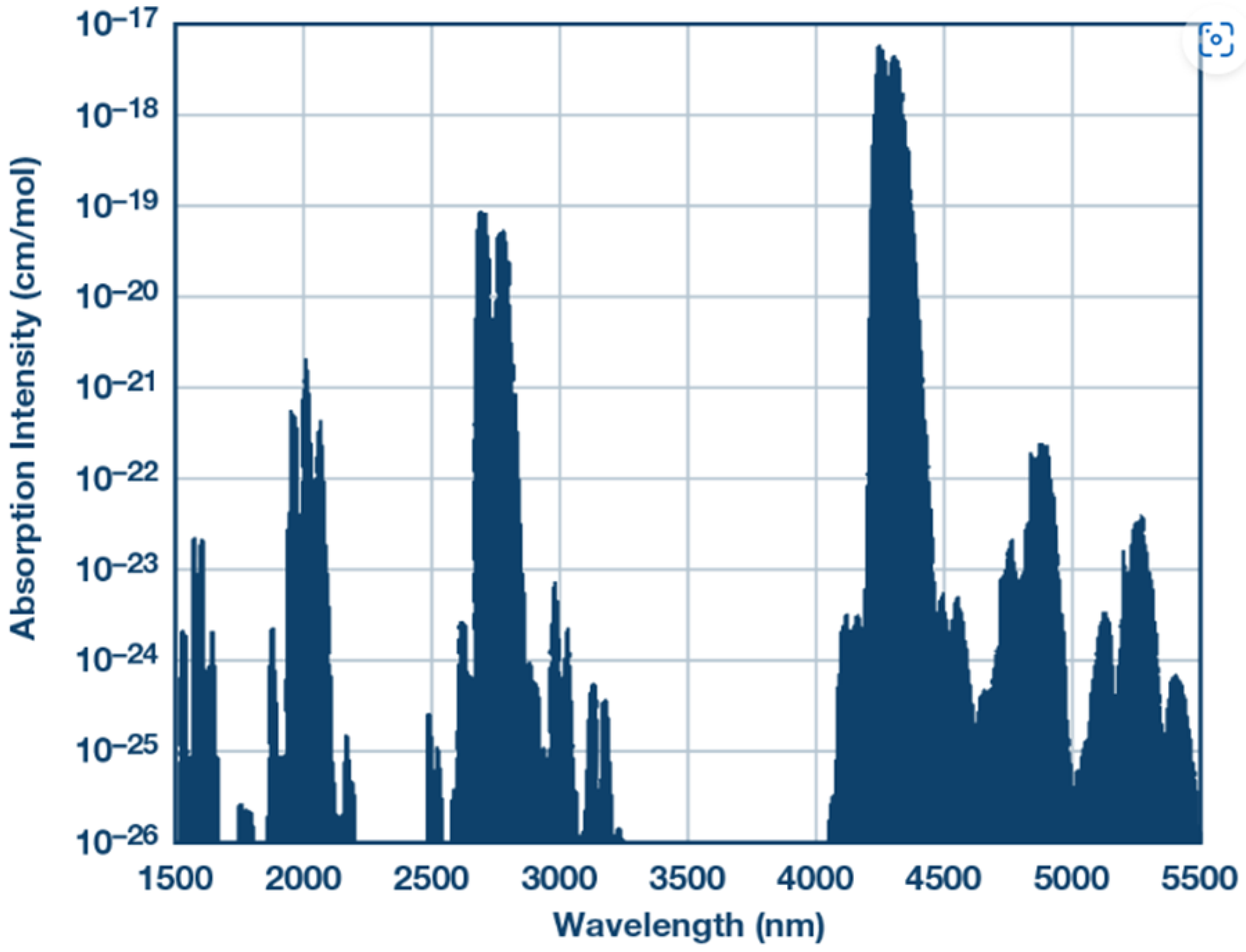
CO₂ concentration is quantified using a non-dispersive infrared (NDIR) sensor, which operates by directing infrared radiation through a sample chamber containing the gas mixture. Because CO₂ exhibits a unique and strong infrared absorption band centered at 4.26 μm, the attenuation of transmitted infrared intensity at this wavelength is directly proportional to CO₂ concentration via the Beer-Lambert law. The measurement system employs three chambers arranged in series: the first chamber establishes the baseline (inlet) CO₂ concentration; the second chamber houses the artificial photosynthesis system, where CO₂ is consumed; and the third chamber measures the outlet CO₂ concentration post-reaction. The difference between inlet and outlet concentrations quantifies the CO₂ captured and converted per unit time.
Figure 4.
Infrared absorption spectrum of CO₂ showing the characteristic absorption band at 4.26 μm used for NDIR detection [19].
Figure 4.
Infrared absorption spectrum of CO₂ showing the characteristic absorption band at 4.26 μm used for NDIR detection [19].
4.2. O₂ Measurement: Electrochemical Oxygen Sensor
The concentration of oxygen released by the photosynthetic reactor is measured using an electrochemical oxygen sensor positioned at the reactor outlet. The sensor generates a current proportional to the partial pressure of O₂ in the gas stream, enabling continuous, real-time monitoring of O₂ production. Sensor readings are logged by a data acquisition system and cross-correlated with CO₂ concentration measurements to compute the overall CO₂-to-O₂ conversion efficiency of the system.
4.3. Reactor
A fluidized bed reactor is employed as the primary reaction vessel for the artificial photosynthesis process. The fluidized bed configuration ensures intimate contact between the cobalt oxide catalyst particles, the CO₂ feed gas, and the water spray, maximizing mass transfer and reaction efficiency. The reactor is equipped with a temperature control system to maintain the target operating temperature of 70°C, a water inlet port connected to a peristaltic pump, and a gas outlet connected to the oxygen sensor.
4.4. Thermal Energy Storage System
Solar thermal energy is stored in a hot silicon thermal energy storage (TES) unit, which captures incident solar radiation during daylight hours and releases stored heat on demand to maintain reactor temperature during periods of low irradiance. This decoupling of energy collection from energy utilization ensures continuous 24-hour system operation, overcoming the intermittency limitation that constrains direct solar photovoltaic systems.
5. System Performance Analysis and Impact Projections
5.1. Stoichiometric Performance
From the stoichiometry of Equation (11), the molar masses of CO₂ (44 g/mol) and O₂ (32 g/mol), and their 1:1 molar ratio in the balanced equation (6 mol CO₂ consumed per 6 mol O₂ produced), the mass-based CO₂-to-O₂ conversion ratio is:
Mass ratio = 6 × 32 / 6 × 44 = 32/44 ≈ 0.727 kg O₂ per kg CO₂
Accordingly, 1 kg of CO₂ captured and fully converted by the photosynthesis reactor yields approximately 0.73 kg of O₂. To reduce CO₂ concentration by 1 ppm in a space of 1,000 m³ volume, the system must capture and convert approximately 1 kg of CO₂, releasing 0.73 kg of O₂ into the space. The overall system conversion efficiency target is set at ≥ 80%, accounting for absorption efficiency, desorption losses, and incomplete photocatalytic conversion.
5.2. National-Scale Impact Projections
According to projections from the U.S. Energy Information Administration (EIA) and Department of Energy (DOE), widespread adoption of artificial photosynthesis technology could deliver energy-equivalent savings of 3.4 quads (residential) and 3.9 quads (commercial) per year by 2030 [Hughes, 2008]. At the average U.S. electricity retail rate of $0.1688/kWh (July 2024), this corresponds to annual national savings of approximately $200 billion.
In terms of fossil fuel displacement, nationwide deployment at scale could eliminate the need for approximately 732 million barrels of oil, 152 million tonnes of coal, 4 trillion cubic feet of natural gas, or 32 billion gallons of gasoline annually. The CO₂ reduction potential is calculated using the combustion stoichiometry of gasoline (C₈H₁₈, density 0.75 kg/L):
C₈H₁₈ + 25/2 O₂ → 8 CO₂ + 9 H₂O
Molar mass of C₈H₁₈: 114 g/mol; Molar mass of 8×CO₂: 352 g/mol → Mass ratio CO₂/fuel≈ 3.09
The elimination of 32 billion gallons of gasoline (equivalent to approximately 98.84 billion metric tonnes of fuel) corresponds to a CO₂ reduction of approximately 302,600 million metric tonnes. This represents roughly 50 times the current annual U.S. greenhouse gas emission equivalent of 6,343 million metric tonnes CO₂e [EIA, 2024]. At an assumed carbon abatement cost of $200 per tonne, this reduction translates to a potential national saving of approximately $60.5 trillion in carbon capture and storage expenditures — an extraordinary economic case for artificial photosynthesis at scale.

Table 2.
Projected national-scale impact metrics for widespread artificial photosynthesis deployment.
Table 2.
Projected national-scale impact metrics for widespread artificial photosynthesis deployment.
| Impact Metric | Projected Value |
|---|---|
| Annual national energy cost savings (2030) | ~$200 billion USD |
| CO₂ emission reduction (gasoline equivalent) | ~302,600 million metric tonnes |
| Carbon abatement cost savings (@ $200/tonne CO₂) | ~$60.5 trillion USD |
| Fossil fuel displaced (oil equivalent) | ~732 million barrels/year |
| Fossil fuel displaced (natural gas equivalent) | ~4 trillion ft³/year |
| O₂ produced per kg CO₂ converted | 0.73 kg O₂ |
| Target system conversion efficiency | ≥ 80% |
| CO₂ capture rate vs. natural tree (per unit area) | ~1,000× higher |
6. Comparative Analysis with Existing Decarbonization ApproacheS
Artificial photosynthesis occupies a distinct and superior position relative to existing decarbonization strategies when evaluated on the dimension of permanent CO₂ transformation rather than merely displacement or sequestration. The principal competing approaches are evaluated below.
6.1. Carbon Capture and Storage (CCS)
CCS involves capturing CO₂ from point sources, compressing it, and injecting it into geological formations for long-term storage. Despite decades of development and significant public investment, global CCS capacity captures only approximately 0.1% of total annual CO₂ emissions [28,29]. Persistent barriers include high capital and operating costs, uncertain long-term containment integrity, risk of CO₂ leakage, and public opposition to subsurface storage [30]. Critically, CCS does not transform CO₂; it merely relocates it, leaving the fundamental issue unresolved and creating new long-term liabilities.
6.2. Hydrogen Production
Hydrogen is widely regarded as a promising clean fuel carrier. However, the dominant production pathways carry significant CO₂ implications: #F5F5F5 hydrogen (produced from natural gas via steam methane reforming without carbon capture) generates substantial direct CO₂ emissions; blue hydrogen (#F5F5F5 hydrogen with CCS) inherits the limitations of CCS described above [26,27]; and green hydrogen (produced via electrolysis powered by renewable electricity) remains prohibitively expensive at current technology readiness levels, with estimated production costs significantly exceeding those of fossil-derived hydrogen [24,25].
6.3. CO₂-Enhanced Oil Recovery (CO₂-EOR)
CO₂-EOR utilizes injected CO₂ to mobilize residual oil in depleted reservoirs, providing an economic incentive for CO₂ utilization. However, the recovered oil is subsequently combusted, re-releasing the injected CO₂ and additional carbon from the oil itself, making the approach thermodynamically unsustainable on a net-emissions basis [31].
6.4. Artificial Photosynthesis — Transformative Advantage
In contrast to the above approaches, artificial photosynthesis does not merely capture, store, or displace CO₂; it chemically transforms CO₂ into O₂ and energy-rich organic compounds. This transformation is irreversible under the intended operating conditions and yields two direct co-benefits: reduction of atmospheric CO₂ and simultaneous production of oxygen, which is essential to sustaining aerobic life. Moreover, the hydrogen produced as a co-product (via Equation 5) can be utilized as a clean fuel for internal combustion engines or fuel cells, further diversifying the system's value proposition. Table 3 provides a systematic comparison.
7. Relation to Prior ReseARCH
The scientific literature on CO₂ capture and artificial photosynthesis is extensive. Santori et al. [9] proposed an adsorption-based artificial tree system for atmospheric CO₂ capture, purification, and compression, providing foundational thermodynamic analysis of the capture cycle. Barzagli et al. [10] demonstrated CO₂ capture using aqueous Na₂CO₃ with calcium chloride (CaCl₂) for pure CO₂ recovery at ambient conditions, validating the sodium carbonate absorption pathway employed in the present work. Xiao et al. [6,11] conducted systematic structure-activity relationship studies of tertiary amines for post-combustion CO₂ capture, establishing the thermodynamic constraints that motivate the selection of Na₂CO₃ as the preferred absorbent in this study.
Lackner [12] provided a rigorous thermodynamic analysis demonstrating that the free energy requirement for direct air capture of CO₂ is intrinsically small, supporting the feasibility of large-scale CO₂ capture. Zhang et al. [13] analyzed multi-stage temperature swing adsorption systems for CO₂ enrichment, and Drechsler and Agar [14] investigated water co-adsorption effects in solid sorbent direct air capture, both providing insights relevant to the desorption unit design in this work. Li et al. [15] demonstrated nanoparticle-enhanced CO₂ absorption in the Rectisol process, offering potential future improvements to the absorption efficiency of the Na₂CO₃ system. Applications of CO₂ in enhanced oil recovery were reported by Bhavsar et al. [16], Al-Shargabi et al. [17], and Alam et al. [18], contextualizing the limitations of CO₂-EOR relative to the transformative approach pursued here.
The present work advances beyond the existing literature by integrating CO₂ capture (via Na₂CO₃ absorption) and photocatalytic CO₂ conversion (via cobalt oxide-catalyzed artificial photosynthesis) into a single continuous system, with the specific objective of producing oxygen as the primary output rather than sequestering or otherwise displacing CO₂. To the authors' knowledge, no prior study has demonstrated this integrated capture-conversion-oxygen-production system in a laboratory-scale continuous flow configuration.
8. Conclusions
This paper has presented the design, theoretical foundations, and experimental framework of an integrated artificial photosynthesis system for CO₂ capture and oxygen production. The following principal conclusions are drawn:
- The proposed system successfully integrates three functional units — Na₂CO₃ absorption, thermal desorption, and cobalt oxide-catalyzed photosynthetic reaction — into a continuous process that mirrors the essential function of natural tree photosynthesis while achieving CO₂ capture rates approximately 1,000 times greater per unit area.
- Sodium carbonate is demonstrated to be a superior absorbent relative to amine compounds for this application, offering lower cost, lower energy consumption for regeneration, negligible corrosivity, and non-toxicity, while providing simultaneous removal of SO₂ and HCl impurities from the flue gas stream.
- Cobalt oxide is identified as the optimal photocatalyst for the artificial photosynthesis reactor, combining chemical stability, high catalytic activity, earth-abundance, and compatibility with solid-state fluidized bed operation.
- Stoichiometric analysis confirms a CO₂-to-O₂ mass conversion ratio of 0.73 kg O₂ per kg CO₂, with a system-level efficiency target of ≥ 80% established as the key performance indicator.
- National-scale deployment projections indicate the potential for approximately $200 billion in annual energy cost savings by 2030, reduction of 302,600 million metric tonnes of CO₂ emissions, and savings of approximately $60.5 trillion in carbon abatement costs — establishing an extraordinarily compelling economic and environmental case for technology development.
- Comparative analysis confirms that artificial photosynthesis offers a fundamentally superior outcome relative to CCS, hydrogen production, and CO₂-EOR, by permanently transforming CO₂ into oxygen and energy-rich compounds rather than merely sequestering, relocating, or displacing it.
Future research will focus on laboratory-scale demonstration of the integrated system, optimization of cobalt oxide catalyst loading and particle size, investigation of Nafion® membrane performance under continuous operation, evaluation of system performance across a range of CO₂ feed concentrations, and development of a validated scale-up model for industrial deployment. Applications beyond terrestrial energy systems — including life support in extraterrestrial environments such as the Martian atmosphere, which is approximately 95% CO₂ — provide further motivation for advancing this technology.
References
- U.S. Department of Agriculture, Forest Service. (2023). Trees are climate change carbon storage heroes. Retrieved from https://www.fs.usda.gov/features/trees-are-climate-change-carbon-storage-heroes.
- PhysOrg. (2009). Synthetic tree captures carbon faster than real trees. Retrieved from https://phys.org/news/2009-07-synthetic-tree-captures-carbon-faster.html.
- U.S. Department of Agriculture, Food Safety and Inspection Service. (2020). Carbon Dioxide Fact Sheet. Retrieved from https://www.fsis.usda.gov.
- U.S. Energy Information Administration. (2023). International Energy Outlook 2023. Retrieved from https://www.eia.gov/outlooks/ieo/.
- International Energy Agency. (2024). Greenhouse Gas Emissions from Energy Data Explorer. Retrieved from https://www.iea.org/data-and-statistics/data-tools/greenhouse-gas-emissions-from-energy-data-explorer.
- Xiao, M., Liu, H., Idem, R., Tontiwachwuthikul, P., & Liang, Z. (2016). A study of structure–activity relationships of commercial tertiary amines for post-combustion CO₂ capture. Applied Energy, 184, 219–229. [CrossRef]
- Falotico, A. J. (1993). Dry Carbonation of Trona. PCT Application No. PCT/US92/06321 (WO 93/11010). Church and Dwight Co., Inc.
- Church & Dwight, Inc. (2000). Personal communication on Na₂CO₃–NaHCO₃–H₂O phase diagram.
- Santori, G., Charalambous, C., Ferrari, M. C., & Brandani, S. (2018). Adsorption artificial tree for atmospheric carbon dioxide capture, purification and compression. Energy, 162, 1158–1168. [CrossRef]
- Barzagli, F., Giorgi, C., Mani, F., & Peruzzini, M. (2017). CO₂ capture by aqueous Na₂CO₃ integrated with high-quality CaCO₃ formation and pure CO₂ release at room conditions. Journal of CO₂ Utilization, 22, 346–354. [CrossRef]
- Xiao, M., Liu, H., Idem, R., Tontiwachwuthikul, P., & Liang, Z. (2016). A study of structure–activity relationships of commercial tertiary amines for post-combustion CO₂ capture. Applied Energy, 184, 219–229. [CrossRef]
- Lackner, K. S. (2013). The thermodynamics of direct air capture of carbon dioxide. Energy, 50, 38–46. [CrossRef]
- Zhang, Z. X., Xu, H. J., Hua, W. S., & Zhao, C. Y. (2022). Thermodynamics analysis of multi-stage temperature swing adsorption cycle for dilute CO₂ capture, enrichment and purification. Energy Conversion and Management, 265, 115794. [CrossRef]
- Drechsler, C., & Agar, D. W. (2020). Investigation of water co-adsorption on the energy balance of solid sorbent based direct air capture processes. Energy, 192, 116587. [CrossRef]
- Li, L., Zhang, C., Chen, Y., & Liu, X. (2022). The use of nanoparticles for high-efficiency CO₂ capture by methanol. Journal of CO₂ Utilization, 66, 102299. [CrossRef]
- Bhavsar, A., Hingar, D., Ostwal, S., Thakkar, I., Jadeja, S., & Shah, M. (2023). The current scope and stand of carbon capture storage and utilization — A comprehensive review. Case Studies in Chemical and Environmental Engineering, 100368. [CrossRef]
- Al-Shargabi, M., Davoodi, S., Wood, D. A., Rukavishnikov, V. S., & Minaev, K. M. (2022). Carbon dioxide applications for enhanced oil recovery assisted by nanoparticles: Recent developments. ACS Omega, 7(12), 9984–9994. [CrossRef]
- Alam, M. M. M., Hassan, A., Mahmoud, M., Sibaweihi, N., & Patil, S. (2022). Dual benefits of enhanced oil recovery and CO₂ sequestration: The impact of CO₂ injection approach on oil recovery. Frontiers in Energy Research, 10, 877212. [CrossRef]
- ADI Analog Dialogue. (2021). Complete Gas Sensor Circuit Using Nondispersive Infrared. Retrieved from https://www.analog.com/en/analog-dialogue/articles/complete-gas-sensor-circuit-using-nondispersive-infrared.html.
- Cai, T., Johnson, J. K., Wu, Y., & Chen, X. (2019). Toward understanding the kinetics of CO₂ capture on sodium carbonate. ACS Applied Materials & Interfaces, 11(9), 9033–9041. [CrossRef]
- Furcas, F. E., Pragot, W., Chacartegui, R., & Afzal, W. (2020). Sodium carbonate-based post combustion carbon capture utilising trona as main sorbent feed stock. Energy Conversion and Management, 208, 112484. [CrossRef]
- Rodríguez-Mosqueda, R., Bramer, E. A., & Brem, G. (2018). CO₂ capture from ambient air using hydrated Na₂CO₃ supported on activated carbon honeycombs with application to CO₂ enrichment in greenhouses. Chemical Engineering Science, 189, 114–122. [CrossRef]
- Cai, Y., Wang, W., Li, L., Wang, Z., Wang, S., Ding, H., … & Wang, W. (2018). Effective capture of carbon dioxide using hydrated sodium carbonate powders. Materials, 11(2), 183. [CrossRef]
- de León, C. M., Ríos, C., & Brey, J. J. (2023). Cost of green hydrogen: limitations of production from a stand-alone photovoltaic system. International Journal of Hydrogen Energy, 48(32), 11885–11898. [CrossRef]
- Ordóñez, D. F., Ganzer, C., Halfdanarson, T., Garay, A. G., Patrizio, P., Bardow, A., … & Mac Dowell, N. (2023). Quantifying global costs of reliable green hydrogen. Energy Advances.
- George, J. F., Müller, V. P., Winkler, J., & Ragwitz, M. (2022). Is blue hydrogen a bridging technology? — The limits of a CO₂ price and the role of state-induced price components for green hydrogen production in Germany. Energy Policy, 167, 113072. [CrossRef]
- de Kleijne, K., de Coninck, H., van Zelm, R., Huijbregts, M. A., & Hanssen, S. V. (2022). The many greenhouse gas footprints of green hydrogen. Sustainable Energy & Fuels, 6(19), 4383–4387. [CrossRef]
- Farouq Ali, S. M., & Soliman, M. Y. (2023). Limitations and Fallacies of Carbon Capture and Storage (CCS) and Impact on Oil and Gas Production. SPE Annual Technical Conference and Exhibition, D031S038R003.
- Bajpai, S., Shreyash, N., Singh, S., Memon, A. R., Sonker, M., Tiwary, S. K., & Biswas, S. (2022). Opportunities, challenges and the way ahead for carbon capture, utilization and sequestration (CCUS) by the hydrocarbon industry. Energy Reports, 8, 15595–15616. [CrossRef]
- Hanisch, C. (1998). The pros and cons of carbon dioxide dumping. Environmental Science & Technology, 32(1), 20A–24A. [CrossRef]
- Farajzadeh, R., Eftekhari, A. A., Dafnomilis, G., Lake, L. W., & Bruining, J. (2020). On the sustainability of CO₂ storage through CO₂-enhanced oil recovery. Applied Energy, 261, 114467. [CrossRef]
Figure 1.
Simplified process flowchart of the integrated CO₂ capture and artificial photosynthesis system.
Figure 1.
Simplified process flowchart of the integrated CO₂ capture and artificial photosynthesis system.

Figure 2.
Detailed schematic of the experimental system, showing absorption tower, heat exchanger, desorption unit, and photosynthesis reactor.
Figure 2.
Detailed schematic of the experimental system, showing absorption tower, heat exchanger, desorption unit, and photosynthesis reactor.
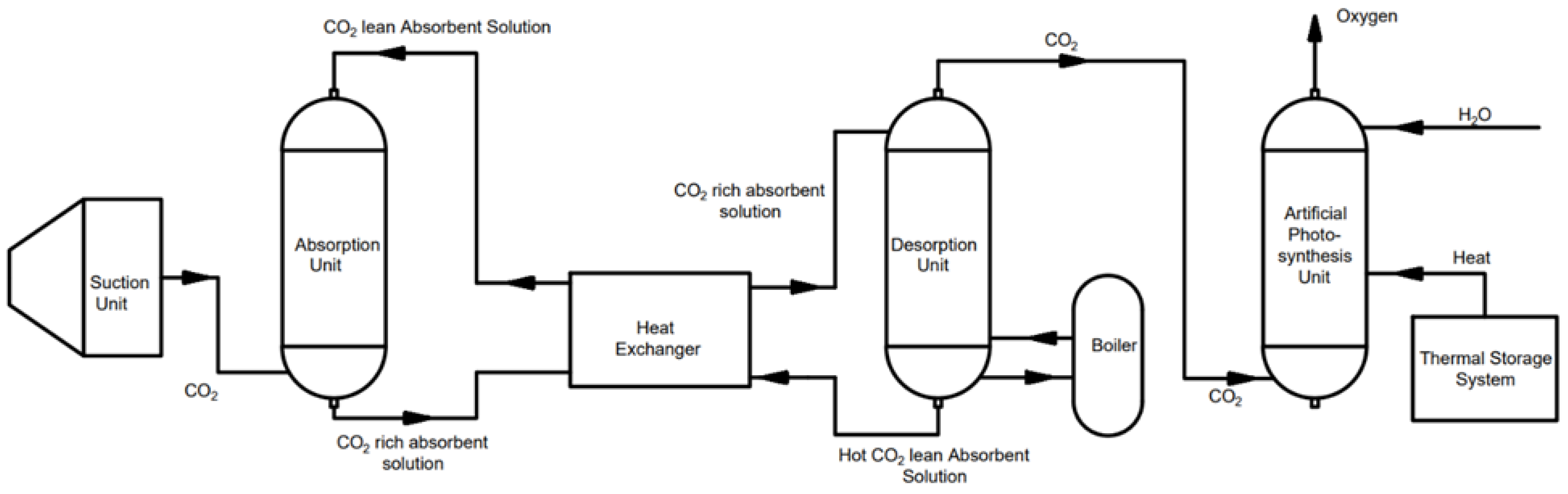
Figure 3.
Project timeline presented as a Gantt chart across the 24-month project duration.
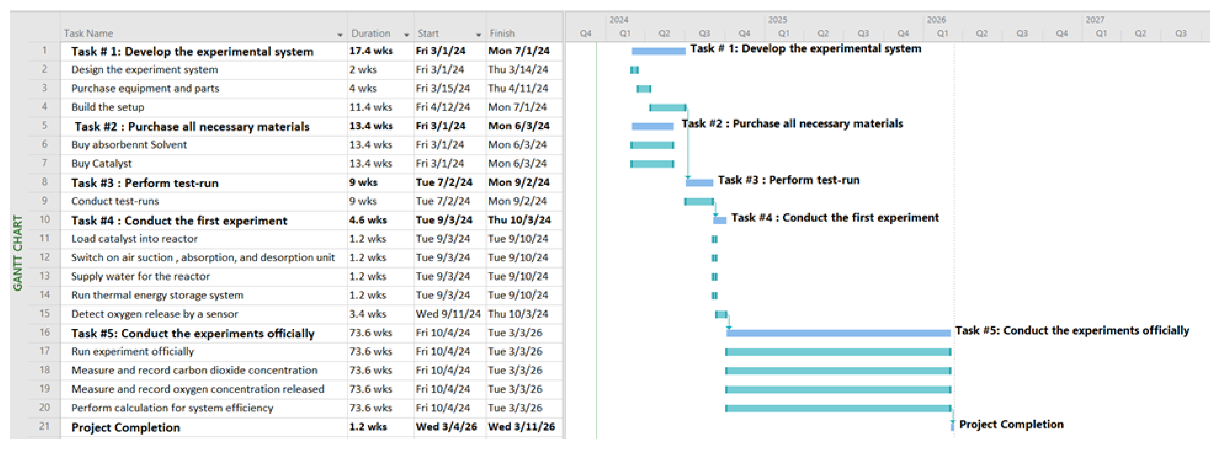
Table 1.
Summary of experimental tasks, durations, activities, and success criteria.
| Task | Duration | Activities | Success Criteria |
|---|---|---|---|
| 1 | Months 1–4 | Procure and assemble experimental equipment; verify system integrity (no leaks) | All components operational; zero-leak confirmation |
| 2 | Months 1–3 | Procure Na₂CO₃ solvent and Co₃O₄ catalyst; prepare absorbent solution | Materials delivered on schedule; solution prepared at target concentration |
| 3 | Months 5–6 | Conduct test runs; verify absorption and desorption unit performance | Smooth system operation; consistent CO₂ uptake in absorption unit |
| 4 | Month 7 | Conduct first official experiment; detect O₂ release | Positive O₂ signal detected by oxygen sensor |
| 5 | Months 8–24 | Run systematic experiments; measure CO₂ and O₂ concentrations; calculate efficiency | System CO₂-to-O₂ conversion efficiency ≥ 80% |
Table 3.
Comparative evaluation of decarbonization approaches across key technical, environmental, and economic criteria.
Table 3.
Comparative evaluation of decarbonization approaches across key technical, environmental, and economic criteria.
| Criterion | CCS | Green H₂ | CO₂-EOR | Artificial Photosynthesis |
|---|---|---|---|---|
| CO₂ permanently removed? | No (stored) | Partial | No | Yes (converted) |
| CO₂ transformed into useful product? | No | No | No | Yes (O₂, glucose, H₂) |
| Energy self-sufficient? | No | Partial | Partial | Yes (solar) |
| Scalability | Limited | High | Limited | High |
| Environmental co-benefit | None | Low | Negative | O₂ production |
| Technology Readiness Level | TRL 8–9 | TRL 5–7 | TRL 8–9 | TRL 3–4 (this work) |
| Cost trajectory | High / stagnant | Declining | Moderate | Early-stage / high potential |
Disclaimer/Publisher’s Note: The statements, opinions and data contained in all publications are solely those of the individual author(s) and contributor(s) and not of MDPI and/or the editor(s). MDPI and/or the editor(s) disclaim responsibility for any injury to people or property resulting from any ideas, methods, instructions or products referred to in the content. |
© 2026 by the author. Licensee MDPI, Basel, Switzerland. This article is an open access article distributed under the terms and conditions of the Creative Commons Attribution (CC BY) license.
Copyright: This open access article is published under a Creative Commons CC BY 4.0 license, which permit the free download, distribution, and reuse, provided that the author and preprint are cited in any reuse.


