

Submitted:
25 March 2026
Posted:
25 March 2026
You are already at the latest version
Abstract
Large diameter axial ventilation fans are widely used in poultry houses to regulate ai flow, temperature, and air quality. However, conventional induction motors driving these fans typically operate at fixed speed and suffer efficiency degradation under low speed, high torque conditions due to slip induced rotor copper losses. This study presents an experimental investigation of a manufacturing constrained conversion of a commercial induction motor platform into a direct drive surface permanent magnet synchronous motor (PMSM). Instead of developing a completely new motor design, the proposed approach reuses the existing stator lamination, housing structure, and winding production process while redesigning the rotor electromagnetic structure to incorporate surface-mounted permanent magnets. Experimental testing was conducted using a dynamo meter based measurement system to evaluate the performance of both the commercial induction motor and the converted PMSM prototype. The results show that the commercial induction motor exhibits significant efficiency degradation at high torque due to increased slip, whereas the PMSM eliminates slip dependent rotor copper losses and maintains efficiencies above 88% within the typical ventilation operating range of 650-750 rpm. The study further relates airflow demand to rotational speed using fan affinity laws, highlighting the cubic relationship between speed and input power and demonstrating the energy-saving potential of variable speed PMSM drives. The proposed conversion framework therefore provides a practical pathway for improving the energy efficiency of agricultural ventilation systems while maintaining compatibility with existing motor manufacturing infrastructure.
Keywords:
permanent magnet synchronous motor
; induction motor conversion
; agricultural ventilation systems
; direct drive fan systems
; motor efficiency improvement
1. Introduction
Large diameter axial ventilation fans are widely deployed in poultry houses to maintain appropriate airflow, thermal comfort, and air quality across different stages of bird growth. Ventilation demand in poultry farming varies significantly with bird age, stocking density, and environmental conditions. Younger birds typically require lower airflow rates to maintain stable thermal conditions [14,15,16,33], whereas mature birds require significantly higher ventilation capacity to remove excess heat, moisture, and ammonia accumulation. Consequently, modern poultry ventilation systems require demand following airflow control rather than fixed speed operation.
In typical agricultural installations, ventilation fans with diameters around 50 inches (approximately 1.27 m) are commonly used due to their ability to deliver large airflow volumes at relatively low rotational speeds. However, the large fan diameter inherently requires high torque at low rotational speeds, which presents significant challenges for conventional motor drives. Many existing systems employ multi pole induction motors operating directly from the power grid at fixed frequency. As illustrated in Figure 1a, the commercial ventilation system typically consists of a three phase AC supply driving an induction motor connected directly to a large axial fan. Although induction motors [1,2,3,4,5,6,7,8,9,10] are robust and widely used in industrial applications, their fixed speed operation limits their ability to match ventilation demand under varying farm conditions.
In contrast, inverter fed permanent magnet synchronous motors (PMSMs) enable flexible speed control and improved torque density, making them suitable for demand-following ventilation applications. As shown in Figure 1b, the proposed system replaces the commercial induction motor with a direct drive PMSM controlled by an inverter, allowing continuous speed regulation within the operational range required by agricultural ventilation systems. This demand following capability is particularly important for large axial fans where airflow and power consumption strongly depend on rotational speed.
The physical relationship between airflow and fan speed can be explained using fan affinity laws. For geometrically similar fans operating under similar aerodynamic conditions, airflow rate is proportional to rotational speed, while input power is proportional to the cube of speed. Figure 2 illustrates the normalized relationship between rotational speed, airflow, and input power according to fan affinity laws. This cubic relationship indicates that small reductions in rotational speed can significantly reduce power consumption. Consequently, the ability to regulate motor speed according to ventilation demand can substantially improve the overall energy efficiency [5,6] of agricultural ventilation systems.
Despite the advantages of variable speed operation, commercial ventilation systems based on induction motors exhibit several fundamental limitations under low speed, high torque conditions. When induction motors operate under increasing mechanical load, the rotor speed decreases relative to the synchronous speed, resulting in increased slip [10]. This slip generates rotor currents that produce torque but simultaneously introduce rotor copper losses. The magnitude of rotor copper loss increases proportionally with slip, leading to substantial efficiency degradation under heavy load conditions. Figure 3 conceptually illustrates the slip [1,2] dependent loss mechanism in induction motors. Under high-torque conditions, slip levels can exceed 20%, resulting in significant rotor heating and reduced energy efficiency [9,10,11] within the operating region most relevant to agricultural ventilation.
Permanent magnet synchronous motors provide a fundamentally different torque production mechanism that eliminates slip dependent rotor copper losses. In PMSMs, torque is generated through the interaction between stator current and permanent magnet flux, allowing synchronous operation without rotor current induction. As a result, PMSMs inherently avoid rotor copper loss and can maintain higher efficiency across a broader operating envelope compared with induction motors. These characteristics make PMSMs attractive candidates for direct drive fan applications requiring high torque at relatively low speeds.
However, practical adoption of PMSMs in existing agricultural ventilation systems is often limited by manufacturing constraints. Many agricultural motor platforms have established production lines designed for induction motors, including stator lamination dimensions, housing structures, winding equipment, and assembly processes. Developing an entirely new motor platform can introduce substantial tooling costs and production risks. Therefore, an important challenge in industrial motor development is how to upgrade existing induction motor platforms to PMSM technology while preserving key manufacturing infrastructure.
This study addresses this challenge by proposing a manufacturing constrained conversion framework that transforms a commercial induction motor platform into a direct-drive surface PMSM [14,19]. Instead of developing a completely new motor platform, the proposed design reuses the original stator outer diameter, housing structure, and winding production process while redesigning the rotor to incorporate surface mounted permanent magnets. By maintaining compatibility with existing manufacturing processes, the conversion strategy minimizes tooling modification while enabling high efficiency direct-drive operation.
To validate the proposed approach, comprehensive experimental testing was conducted on both the commercial induction motor and the converted PMSM prototype. The commercial induction motor baseline was characterized through multi point load testing to identify slip dependent efficiency degradation. The proposed PMSM prototype was evaluated through multi speed efficiency mapping within the practical ventilation operating range of 650-750 rpm. The experimental results demonstrate that the PMSM significantly expands the high efficiency operating envelope compared with the commercial induction motor system while enabling flexible demand following speed control.
The main contributions of this work are as follows:
- Experimental identification of slip dominated loss mechanisms in a commercial induction motor driving a large diameter axial fan.
- Development of a manufacturing constrained induction to surface PMSM conversion methodology.
- Comparative analysis of electromagnetic loss redistribution between induction and permanent magnet torque production mechanisms.
- Multi speed efficiency validation of a demand following direct drive PMSM within real ventilation operating conditions.
- System level analysis linking ventilation demand, fan affinity laws [6], and electrical efficiency improvement.
2. Materials and Methods
2.1. Literature Background and Theoretical Basis
The design of energy efficient electric drives for large diameter ventilation fans has attracted increasing attention in agricultural and industrial applications. Poultry houses, livestock facilities, and greenhouse ventilation systems require continuous airflow regulation to maintain appropriate thermal comfort, humidity control, and air quality. As illustrated in Figure 4, ventilation fans in such applications are commonly driven by electric motors operating in the low speed, high torque region. Consequently, the selection of motor topology and drive configuration significantly affects system efficiency and operational flexibility.
2.1.1. Direct Drive PMSMs for Ventilation and Fan Applications
Permanent magnet synchronous motors (PMSMs) have become increasingly attractive for applications requiring high torque density and high efficiency over a wide operating range. Compared with conventional induction motors, PMSMs generate torque through the interaction between stator current and the magnetic field produced by permanent magnets [19,20,21]. This mechanism eliminates the need for rotor current induction, which in turn removes rotor copper losses associated with slip.
Several studies have investigated the application of PMSMs in fan and ventilation systems due to their superior efficiency and controllability. Direct drive PMSM solutions eliminate mechanical transmission components such as gearboxes or belt drives, thereby reducing mechanical losses and maintenance requirements. Furthermore, PMSMs can operate efficiently over a wide speed range when combined with inverter based control, enabling demand following operation that is particularly beneficial in ventilation systems where airflow demand varies with environmental conditions.
For large diameter axial fans used in agricultural ventilation, direct drive PMSMs offer several advantages. First, the high torque density of PMSMs enables direct coupling between the motor shaft and the fan without intermediate transmission mechanisms. Second, inverter fed PMSMs allow continuous speed regulation, enabling the fan to operate at different airflow levels depending on the ventilation requirements. Despite these advantages, practical implementation of PMSM solutions in existing ventilation systems remains limited in many agricultural facilities because commercial installations are often based on standardized induction motor platforms with well established manufacturing processes.
2.1.2. Induction Motor Loss Under Low Speed, High Torque Operation
Induction motors [1,2,3,4,5,6,7,8] remain among the most widely used electric machines in industrial applications due to their robustness, simplicity, and relatively low cost. However, their performance characteristics under low speed, high torque operation can be significantly limited by slip dependent losses. In an induction motor, electromagnetic torque is produced by currents induced in the rotor conductors as a result of the relative speed difference between the stator rotating magnetic field and the rotor mechanical speed [18,20,21].
The synchronous speed of an induction motor is determined by the supply frequency and the number of poles according to Equation (1):
where is the synchronous speed in revolutions per minute, is the electrical frequency, and is the number of poles.
Under load conditions, the rotor rotates at a slightly lower speed than the synchronous speed. The difference between these two speeds is defined as the slip according to Equation (2):
where is the rotor speed. Slip is necessary for torque production in induction motors, but it also introduces additional electrical losses in the rotor conductors.
As the mechanical load increases, the rotor speed decreases, causing the slip to increase. The induced rotor current rises accordingly, leading to increased rotor copper losses. This mechanism is particularly significant in applications requiring high torque at relatively low speeds, such as large diameter axial fans.
2.1.3. Fan Affinity Laws and Ventilation Demand
The operating characteristics of ventilation systems are governed not only by motor performance but also by the aerodynamic behavior of the fan. For geometrically similar fans operating in similar flow regimes, fan affinity laws describe the relationship between rotational speed, airflow rate, pressure rise, and power consumption as follows:
Equation (3):
Equation (4):
Equation (5):
where represents airflow rate, represents pressure rise across the fan, represents input power, and represents rotational speed.
The cubic relationship between power consumption and rotational speed indicates that small changes in fan speed can lead to significant changes in power demand. This principle forms the basis of energy efficient ventilation strategies based on variable speed control.
2.1.4. Manufacturing Constrained Conversion and Research Gap
While the performance advantages of PMSMs are well recognized, their widespread adoption in existing agricultural ventilation systems is often constrained by manufacturing considerations. Many agricultural motors are produced on established induction motor platforms, where the stator laminations, housing structures, and winding [13] processes are optimized for large scale production. Introducing an entirely new motor design [22,23,24] may require significant changes to tooling, production equipment, and assembly procedures.
Recent research has therefore explored retrofit and conversion approaches that upgrade existing motor platforms while preserving key manufacturing infrastructure. Nevertheless, most existing studies on PMSM [25,26,27,28,29,30,31,32,33,34] design focus primarily on electromagnetic optimization [12] without considering the constraints imposed by baseline manufacturing platforms. Similarly, many studies on fan drive systems investigate variable speed operation but do not explicitly examine the conversion of existing induction motor platforms to PMSM architectures.
From the literature reviewed above, three research gaps can be identified. First, relatively few studies investigate the conversion of existing induction motor platforms to PMSM designs under realistic manufacturing constraints. Second, previous studies on ventilation fan applications rarely provide experimental baseline comparisons with commercial induction motor systems. Third, most motor design studies focus primarily on electromagnetic optimization without explicitly linking motor performance to demand-following ventilation requirements governed by fan affinity laws.
To address these gaps, the present work investigates a manufacturing constrained conversion of an existing induction motor platform to a direct drive surface PMSM designed for large diameter agricultural ventilation fans. By combining experimental baseline measurements of the induction motor with efficiency mapping of the proposed PMSM prototype, this study provides a comprehensive analysis of efficiency improvement and loss redistribution in a practical ventilation application.
2.2. Motor Platform and Conversion Methodology
This section describes the design framework used to convert a baseline induction-motor platform into a direct drive surface PMSM suitable for large diameter agricultural ventilation fans. Unlike conventional PMSM design approaches that begin with a completely new electromagnetic structure, the proposed method is constrained by existing manufacturing infrastructure. Therefore, the design process focuses on reusing the original induction motor platform while modifying only a limited number of key components. The conversion strategy consists of three major stages: identification of the existing motor platform, definition of manufacturing constraints, and redesign of the electromagnetic structure to enable PMSM operation.
2.2.1. Commercial Induction Motor Platform
The baseline system used in this study is a multi pole three phase induction motor platform commonly deployed in agricultural ventilation applications. These motors typically drive large diameter axial fans operating at relatively low rotational speeds. The existing motor platform includes two main configurations: a 6 pole induction motor and an 8 pole induction motor. Both configurations share a common mechanical platform designed for industrial production. The platform includes a standardized stator lamination, housing structure, and winding manufacturing process.
Table 1 summarizes the key design parameters of the baseline induction motors and the converted PMSM prototype.
The most important features of the existing platform include a common stator outer diameter, a common motor housing and mechanical interface, and an existing winding production process. Because the stator, housing, and manufacturing process remain unchanged, the baseline induction motor platform provides a practical foundation for developing a PMSM solution under industrial production constraints.
2.2.2. Manufacturing Constraints
A key novelty of the proposed design lies in the manufacturing constrained conversion framework. Instead of designing a completely new motor structure, the PMSM is developed under strict constraints imposed by the commercial induction motor platform. The original motor housing is retained to preserve mechanical compatibility with the existing agricultural ventilation system. The reused housing structure [17] is shown in Figure 5.
The stator lamination geometry of the original commercial induction motor platform is also preserved. Key stator parameters, including outer diameter, inner diameter, slot structure, and stack length, remain unchanged. The dimensions of the reused stator structure are illustrated in Figure 6, where the stator outer diameter is 160 mm, the inner diameter is 100 mm, the stack length is 95 mm, and the stator contains 36 slots.
The existing winding production process must also be preserved. Only a limited number of components are modified during the conversion process, including the rotor electromagnetic structure, wire diameter, number of turns, and winding connection scheme. By limiting the design modifications to these elements, the conversion strategy enables reuse of most mechanical components and manufacturing processes of the baseline motor platform.
2.2.3. Rotor Conversion and Inverter Based Direct Drive
The conversion of the baseline induction motor platform to a PMSM prototype follows a systematic procedure. In the proposed conversion framework, the rotor of the original induction motor is redesigned to enable synchronous operation while maintaining compatibility with the existing stator geometry. The original rotor of the commercial induction motor employs a conventional squirrel cage structure in which electromagnetic torque is produced through currents induced in the rotor bars. To achieve synchronous torque production, the squirrel cage rotor is replaced with a surface permanent magnet rotor configuration, as illustrated in Figure 7.
Because PMSM operation requires different electromagnetic characteristics compared with induction motors, the stator winding parameters are modified while preserving the original stator slot structure. The main adjustments include the number of turns, wire diameter, and phase connection configuration. In addition, the converted PMSM is operated using an inverter drive to enable variable speed control. A commercially available inverter drive is used to control the PMSM prototype, as shown in Figure 8.
This inverter based control enables the PMSM to operate within the required speed range of approximately 650-750 rpm, which corresponds to the typical operating range of large diameter axial ventilation fans. By regulating the inverter output frequency, the motor speed can be adjusted to follow ventilation demand under different environmental conditions.
2.2.4. Prototype Fabrication
Finally, the PMSM prototype is fabricated based on the existing induction motor platform while incorporating the redesigned permanent magnet rotor and modified stator winding parameters. During the fabrication process, the original motor housing, stator lamination, and mechanical mounting interfaces are preserved in order to maintain compatibility with the existing ventilation fan system. The stator winding implementation of the converted PMSM and the fully assembled PMSM prototype are shown in Figure 9.
2.3. Physics Based Design Considerations
2.3.1. Pole and Slot Configuration
The pole number and stator slot structure significantly influence torque production and back EMF characteristics. The converted PMSM adopts a 6 pole, 36 slot configuration to achieve the required operating speed range for large axial ventilation fans.
2.3.2. Winding Layout
The stator winding of the converted PMSM adopts a distributed three phase winding configuration compatible with the original stator lamination and existing manufacturing process. The winding distribution and phase arrangement are illustrated in Figure 10, where the phase belt and slot allocation corresponding to the 6 pole, 36 slot configuration are shown.
2.3.3. Permanent Magnet Sizing
The dimensions and placement of the surface permanent magnets are determined to provide sufficient air gap magnetic flux for torque production while maintaining compatibility with the existing stator geometry. The selected magnet dimensions are 41 mm in width, 97 mm in arc length, and 2 mm in thickness, as illustrated in Figure 11.
2.3.4. Air Gap Geometry
The air gap length and rotor diameter must be carefully selected to maintain an appropriate balance between electromagnetic performance and mechanical tolerance. Based on the mechanical tolerances of the reused stator structure and the required electromagnetic coupling for direct drive fan operation, the air gap length is selected as 0.5 mm, as illustrated in Figure 12.
2.3.5. Back EMF Design Target and Torque Density
The back-electromotive force (back EMF) constant of the converted PMSM is designed to be compatible with the voltage capability of the inverter drive while supporting the target operating speed range of the agricultural ventilation system. Based on the design target, the measured line to line back EMF of the prototype PMSM is approximately 308 Vrms at the rated speed condition. This value confirms that the selected magnet dimensions and winding configuration provide a suitable balance between torque capability and inverter voltage margin for direct drive ventilation operation.
Because the motor must drive a large axial fan directly, the torque density requirement is higher than in many standard industrial motor applications. The PMSM design therefore aims to achieve sufficient torque at rotational speeds between approximately 650 rpm and 750 rpm.
2.4. Experimental Setup and Measurement Procedure
The motor performance tests were conducted using a dynamometer based measurement system designed for electric motor characterization. The system allows controlled loading of the motor while measuring electrical and mechanical quantities required for efficiency analysis. The main components of the measurement system include power-measurement instruments, a dynamometer test machine, a torque and speed measurement system, an inverter drive controller for PMSM testing, and Magtrol data acquisition software.
Figure 13 shows the complete experimental setup used in this study, including the power measurement instruments and control system, the PMSM prototype mounted on the dynamometer test bench, the Magtrol interface, and the back EMF measurement arrangement.
2.4.1. Commercial Induction Motor Baseline Test
The commercial induction motor serves as the baseline reference for evaluating the performance improvement achieved by the PMSM conversion. The induction motor is operated under fixed frequency conditions without inverter based speed control. Mechanical loading is applied using the dynamometer to obtain torque speed performance data across the operating range. During the test procedure, the following quantities are measured: line voltage, phase current, input electrical power, rotational speed, and mechanical torque.
The mechanical output power is calculated using Equation (6):
where is the measured torque (N·m) and is the rotational speed (rpm).
The efficiency of the motor is calculated as follows:
where is the measured electrical input power.
2.4.2. PMSM Prototype Experimental Test
The converted PMSM prototype is evaluated using a similar dynamometer test setup. However, unlike the induction motor, the PMSM operates with an inverter based drive system that enables variable speed operation. During PMSM testing, the inverter controller regulates the motor speed to predefined operating points corresponding to the expected ventilation operating range of approximately 650–750 rpm. At each operating point, the dynamometer applies mechanical loading while electrical and mechanical parameters are recorded.
2.4.3. Back EMF Measurement
To verify the electromagnetic characteristics of the PMSM prototype, back-EMF measurements are conducted by mechanically driving the PMSM rotor while leaving the stator windings open circuited. The induced voltage waveform is then measured using electrical measurement instruments.
2.4.4. Comparative Evaluation
Although the purpose of this study is to evaluate the performance improvement achieved by converting a baseline induction motor platform to a PMSM architecture, the two systems do not operate under identical boundary conditions. The induction motor operates under fixed frequency conditions without inverter control, whereas the PMSM prototype is driven by an inverter that enables variable speed operation. Therefore, the comparison presented in this work should be interpreted as a comparative baseline under available operating configurations rather than as a strict one to one comparison under identical control conditions. To support this comparison, the performance requirements of the commercial induction motors and the proposed PMSM prototype are summarized in Table 2.
3. Results
The experimental results obtained from the dynamometer based test system were used to evaluate the performance of the converted PMSM prototype and compare it with the commercial induction motor platform. The comparison focuses on efficiency behavior, loss characteristics, and input power consumption under different load and torque conditions relevant to direct drive ventilation systems. All measurements were conducted across multiple load conditions ranging from 25% to 100% load.
3.1. Measured Performance Data
Table 3 and Table 4 summarize the measured performance data of the baseline induction motors and the converted PMSM prototype under different load conditions. The measurements include load, motor, current, input power, torque, speed, output power, and efficiency for load levels ranging from 25% to 100%.
These experimentally obtained data serve as the basis for constructing the performance characteristics presented in Figure 14, Figure 15, Figure 16, Figure 17 and Figure 18. The data clearly illustrate the performance differences between the conventional induction motor platform and the converted PMSM prototype, highlighting the reduction of rotor related losses and the improvement in overall energy efficiency enabled by the PMSM architecture.
3.2. Efficiency Map of the Converted PMSM
To provide a comprehensive view of the operating efficiency of the converted PMSM prototype, an efficiency map is constructed based on the experimentally measured torque and speed data. The resulting distribution is shown in Figure 14.
The efficiency map illustrates the distribution of motor efficiency over a wide range of speed and torque conditions. The results indicate that the PMSM maintains high efficiency over the practical operating region of the ventilation fan system.
3.3. Efficiency Versus Load
The variation of motor efficiency as a function of load level is shown in Figure 15.
The PMSM prototype consistently demonstrates higher efficiency compared with the induction motor across the entire load range. At medium load levels (50–75%), the PMSM reaches efficiencies close to 90%, while the induction motor remains around 80%. The efficiency difference becomes more significant at higher load conditions, where the efficiency of the induction motor decreases due to increasing slip and the associated rotor copper losses.
3.4. Motor Loss Versus Load
The total motor losses as a function of load are presented in Figure 16.
The results show that the induction motor exhibits a substantial increase in losses as load increases, particularly at higher load levels. This behavior is mainly attributed to rotor copper losses, which increase with slip under higher torque demand. In contrast, the PMSM prototype exhibits significantly lower total losses across the entire load range.
3.5. Efficiency Improvement of PMSM over IM
The efficiency improvement achieved by the PMSM relative to the induction motor under different load conditions is shown in Figure 17.
For the 6 pole configuration, the efficiency improvement is relatively moderate at partial load but increases significantly at full load due to the substantial efficiency drop of the induction motor at high load. For the 8 pole configuration, the efficiency improvement remains consistently high across the entire load range.
3.6. Input Power Saving of PMSM over IM
The reduction in electrical input power achieved by replacing the induction motor with the PMSM prototype is shown in Figure 18.
The difference becomes particularly noticeable at higher load levels, where rotor copper losses in the induction motor increase substantially due to higher slip. In contrast, the PMSM maintains lower electrical power consumption because the rotor magnetic field is produced by permanent magnets rather than induced currents.
3.7. Efficiency Versus Torque
The relationship between motor efficiency and output torque is shown in Figure 19.
The PMSM maintains high efficiency across a wide torque range, whereas the induction motor efficiency decreases significantly as torque increases. This characteristic is particularly beneficial for direct drive fan applications, where high torque is required at relatively low rotational speeds.
4. Discussion
The experimental results demonstrate that the manufacturing constrained PMSM conversion framework provides clear efficiency benefits over the original induction motor platform, especially in the low speed, high torque operating region relevant to agricultural ventilation. The most important physical mechanism behind this improvement is the elimination of slip dependent rotor copper losses. In the induction motor, higher torque demand requires increased slip, which causes higher rotor current and larger rotor copper loss. In the PMSM, synchronous torque production is achieved through the interaction between stator current and permanent magnet flux, so rotor copper loss is removed.
The results also show that the proposed conversion does not simply improve peak efficiency at one operating point; it expands the efficient operating envelope across the practical speed range of 650–750 rpm. This feature is particularly important for demand-following ventilation systems, where airflow requirements vary with bird age and environmental conditions. Through fan affinity laws, reduced operating speed directly translates into lower airflow and disproportionately lower input power. Therefore, the inverter fed PMSM not only improves motor efficiency but also enables system level energy savings through variable speed operation.
Another important contribution of this work is its industrial practicality. Rather than proposing a completely new motor platform, the study demonstrates that substantial performance gains can be achieved while preserving the existing stator geometry, motor housing, and core production process. This manufacturing constrained philosophy reduces tooling disruption and can lower the barrier to industrial adoption. In this sense, the present work extends beyond conventional electromagnetic optimization studies by explicitly addressing industrial implementation constraints.
At the same time, the comparison between the induction motor baseline and the PMSM prototype should be interpreted carefully. The PMSM operates with inverter fed variable speed control, whereas the induction motor is evaluated under fixed frequency operation. Although this reflects realistic industrial practice, the two systems are not controlled under identical conditions. Nevertheless, the comparison remains meaningful because it highlights the practical performance advantage of the proposed direct drive PMSM solution under real application constraints.
Future research should extend the present framework in several directions. Long-term thermal and reliability evaluation is needed to assess durability under continuous agricultural operation. Additional studies should also investigate optimization of magnet geometry, winding configuration, and inverter control strategy, as well as extension of the conversion framework to other fan and pump platforms.
5. Conclusions
This study presented a manufacturing constrained conversion approach for transforming a commercial induction motor platform into a direct drive permanent magnet synchronous motor suitable for large diameter agricultural ventilation systems. The proposed method preserves the existing stator geometry, motor housing, and manufacturing infrastructure while redesigning the rotor structure and stator winding configuration to enable synchronous operation.
Experimental validation using a dynamometer based test system demonstrated that the converted PMSM consistently achieves higher efficiency than the conventional induction motor across the operating load range. The efficiency advantage becomes more pronounced at higher load conditions, where the induction motor experiences increased slip and corresponding rotor copper losses. The loss analysis further confirmed that the PMSM maintains substantially lower losses due to the elimination of slip dependent rotor copper losses. As a result, the PMSM prototype shows considerable efficiency improvement, lower input power demand, and a broader high efficiency operating envelope.
Overall, the results confirm that the proposed manufacturing constrained conversion framework provides a practical pathway for upgrading conventional induction motor platforms to PMSM technology while minimizing manufacturing disruption. The proposed approach offers a promising solution for improving the energy efficiency of industrial ventilation systems and other low speed, high torque applications.
Author Contributions
Conceptualization, B.P. and R.R.; methodology, R.R.; validation, R.R., W.W., S.N. and S.P.; formal analysis, R.R. and W.W.; investigation, R.R. and T.M.; resources, W.W and B.P.; data curation, R.R.; writing-original draft preparation, R.R.; writing-review and editing, B.P. and T.M.; supervision, B.P. All authors have read and agreed to the published version of the manuscript.
Funding
This research received no external funding.
Institutional Review Board Statement
Not applicable.
Informed Consent Statement
Not applicable.
Data Availability Statement
The experimental data and analysis procedures used to support the findings of this study are available from the corresponding author upon reasonable request.
Acknowledgments
The authors acknowledge the technical support and experimental facilities provided by Rajamangala University of Technology Thanyaburi.
Conflicts of Interest
The authors declare no conflicts of interest.
References
- Siddique, M.S.; Ertan, H.B.; Alam, M.S.; Khan, M.U. Investigation of harmonic losses to reduce rotor copper loss in induction motors for traction applications. World Electr. Veh. J. 2025, 16, 248. [Google Scholar] [CrossRef]
- Popescu, M.; Di Leonardo, L.; Fabri, G.; Volpe, G.; Riviere, N.; Villani, M. Design of induction motors with flat wires and copper rotor for electric vehicle traction systems. IEEE Trans. Ind. Appl. 2023, 59, 3889–3900. [Google Scholar] [CrossRef]
- Ertan, H.B.; Siddique, M.S.; Koushan, S.; Azuaje-Berbecí, B.J. Designing high power density induction motors for electric propulsion. In Proceedings of the IEEE 20th International Power Electronics and Motion Control Conference (PEMC); IEEE: Brasov, Romania, 2022; pp. 553–558. [Google Scholar]
- Enokizono, M.; Shimoji, H.; Horibe, T. Effect of stator construction of three-phase induction motors on core loss. IEEE Trans. Magn. 2003, 39, 1484–1487. [Google Scholar] [CrossRef]
- Dems, M.; Komeza, K. Designing an energy-saving induction motor operating in a wide frequency range. IEEE Trans. Ind. Electron. 2022, 69, 4387–4397. [Google Scholar] [CrossRef]
- Boldea, I.; Nasar, S.A. Electric Drives; CRC Press: Boca Raton, FL, USA, 2017. [Google Scholar]
- Jahns, T.M.; Soong, W.L. Pulsating torque minimization techniques for permanent magnet AC motor drives—A review. IEEE Trans. Ind. Electron. 1996, 43, 321–330. [Google Scholar] [CrossRef]
- Miller, T.J.E. Brushless Permanent Magnet and Reluctance Motor Drives; Oxford University Press: Oxford, UK, 1989. [Google Scholar]
- Zhu, Z.Q.; Howe, D. Electrical machines and drives for electric, hybrid, and fuel cell vehicles. Proc. IEEE 2007, 95, 746–765. [Google Scholar] [CrossRef]
- Krishnan, R. Permanent Magnet Synchronous and Brushless DC Motor Drives; CRC Press: Boca Raton, FL, USA, 2010. [Google Scholar]
- Gieras, J.F.; Wing, M. Permanent Magnet Motor Technology: Design and Applications, 3rd ed.; CRC Press: Boca Raton, FL, USA, 2017. [Google Scholar]
- Pyrhönen, J.; Jokinen, T.; Hrabovcova, V. Design of Rotating Electrical Machines, 2nd ed.; Wiley: Chichester, UK, 2014. [Google Scholar]
- Bianchi, N. Electrical Machine Analysis Using Finite Elements, 2nd ed.; CRC Press: Boca Raton, FL, USA, 2018. [Google Scholar]
- Fitzgerald, A.E.; Kingsley, C.; Umans, S.D. Electric Machinery, 7th ed.; McGraw-Hill: New York, NY, USA, 2013. [Google Scholar]
- Krause, P.C.; Wasynczuk, O.; Sudhoff, S.D.; Pekarek, S. Analysis of Electric Machinery and Drive Systems, 3rd ed.; Wiley-IEEE Press: Hoboken, NJ, USA, 2013. [Google Scholar]
- Chapman, S.J. Electric Machinery Fundamentals, 5th ed.; McGraw-Hill: New York, NY, USA, 2011. [Google Scholar]
- Binder, A.; Schneider, T.; Klohr, M. Fixing the PM rotor loss problem of PMSM for electric vehicles. IEEE Trans. Ind. Appl. 2017, 53, 439–447. [Google Scholar]
- Hendershot, J.R.; Miller, T.J.E. Design of Brushless Permanent-Magnet Motors; Oxford University Press: Oxford, UK, 2010. [Google Scholar]
- Zhu, Z.Q.; Howe, D. Influence of design parameters on cogging torque in permanent magnet machines. IEEE Trans. Energy Convers. 2000, 15, 407–412. [Google Scholar] [CrossRef]
- Pillay, P.; Krishnan, R. Modeling, simulation, and analysis of permanent magnet motor drives. IEEE Trans. Ind. Appl. 1989, 25, 265–273. [Google Scholar] [CrossRef]
- Li, W.; Chau, K.T.; Jiang, J.Z. Design of permanent-magnet machines for electric vehicles. IEEE Trans. Magn. 2014, 50, 1–4. [Google Scholar]
- Kim, K.C.; Lee, J. Design optimization of permanent magnet synchronous motor for high efficiency. IEEE Trans. Magn. 2015, 51, 1–4. [Google Scholar]
- Jang, G.H.; Park, J.H.; Chang, J.H. Torque ripple reduction in permanent magnet synchronous motors. IEEE Trans. Magn. 2002, 38, 1293–1296. [Google Scholar]
- Aydin, M.; Huang, S.; Lipo, T.A. Torque quality and comparison of internal and surface mounted PM machines. IEEE Trans. Ind. Appl. 2007, 43, 111–116. [Google Scholar]
- Hsu, J.S.; Campbell, S.L. Design considerations for PMSM drives in industrial applications. IEEE Trans. Ind. Appl. 2003, 39, 926–933. [Google Scholar]
- Chen, Z.; Spooner, E. Influence of permanent magnet design on PMSM performance. IEEE Trans. Magn. 1999, 35, 398–403. [Google Scholar]
- Rahman, M.A.; Osheiba, A.M.; Jamaluddin, H. Performance analysis of permanent magnet synchronous motors for variable-speed drives. IEEE Trans. Energy Convers. 1996, 11, 701–708. [Google Scholar]
- Wang, J.; Atallah, K.; Howe, D. Optimal design of permanent magnet machines for high efficiency applications. IEEE Trans. Magn. 2003, 39, 134–137. [Google Scholar]
- Cong, T.T.; Vu, T.N.; Pinto, G.; Quoc, V.D. Optimization design of surface mounted permanent magnet synchronous motors using genetic algorithms. In EAI Endorsed Trans. Energy Web; 2024. [Google Scholar] [CrossRef]
- Ozcelik, N.G.; Ergene, L.T. An improved method for reduction of voltage distortion in IPM EV motors for a better flux weakening capability. IEEE Access 2024, 12, 20125–20136. [Google Scholar] [CrossRef]
- Wu, P.; Sun, Y. A hybrid model for calculating on load performance of delta type IPM machines accounting for rotor and stator saturation. In IEEE Trans. Ind. Electron.; 2024. [Google Scholar] [CrossRef]
- Karthika, M.; Balaji, M.; Kamaraj, V. Design and performance evaluation of an interior permanent magnet synchronous motor for an electric three wheeler. In Proceedings of the 2024 Second International Conference on Emerging Trends in Information Technology and Engineering (ICETITE); IEEE: New Delhi, India, 2024. [Google Scholar] [CrossRef]
- Huynh, T.A.; Hsieh, M.F. Improvement of traction motor performance for electric vehicles using conductors with insulation of high thermal conductivity considering cooling methods. IEEE Trans. Ind. Appl. 2015, 51, 818–826. [Google Scholar] [CrossRef]
Figure 1.
Direct drive ventilation system using (a) an induction motor and (b) a PMSM.
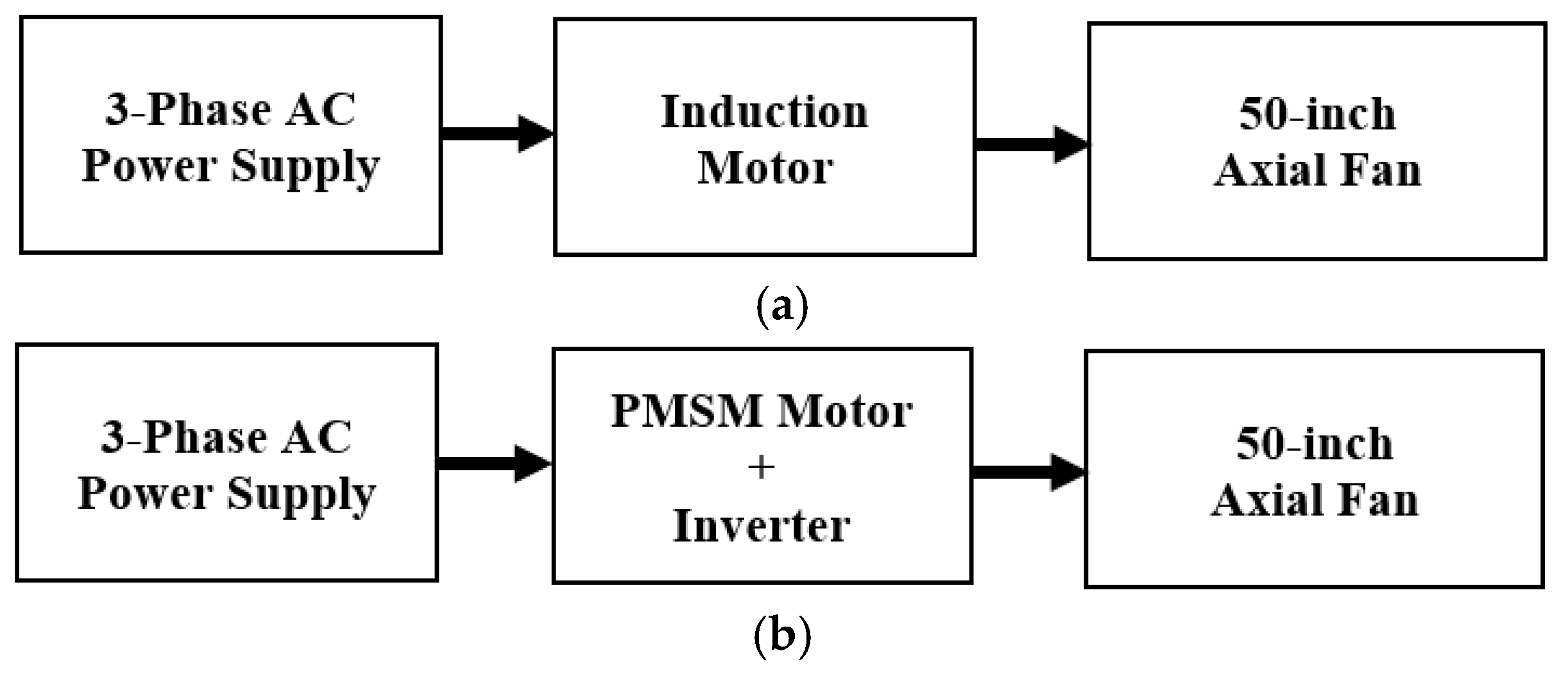
Figure 2.
Normalized relationship between rotational speed, airflow, and input power.
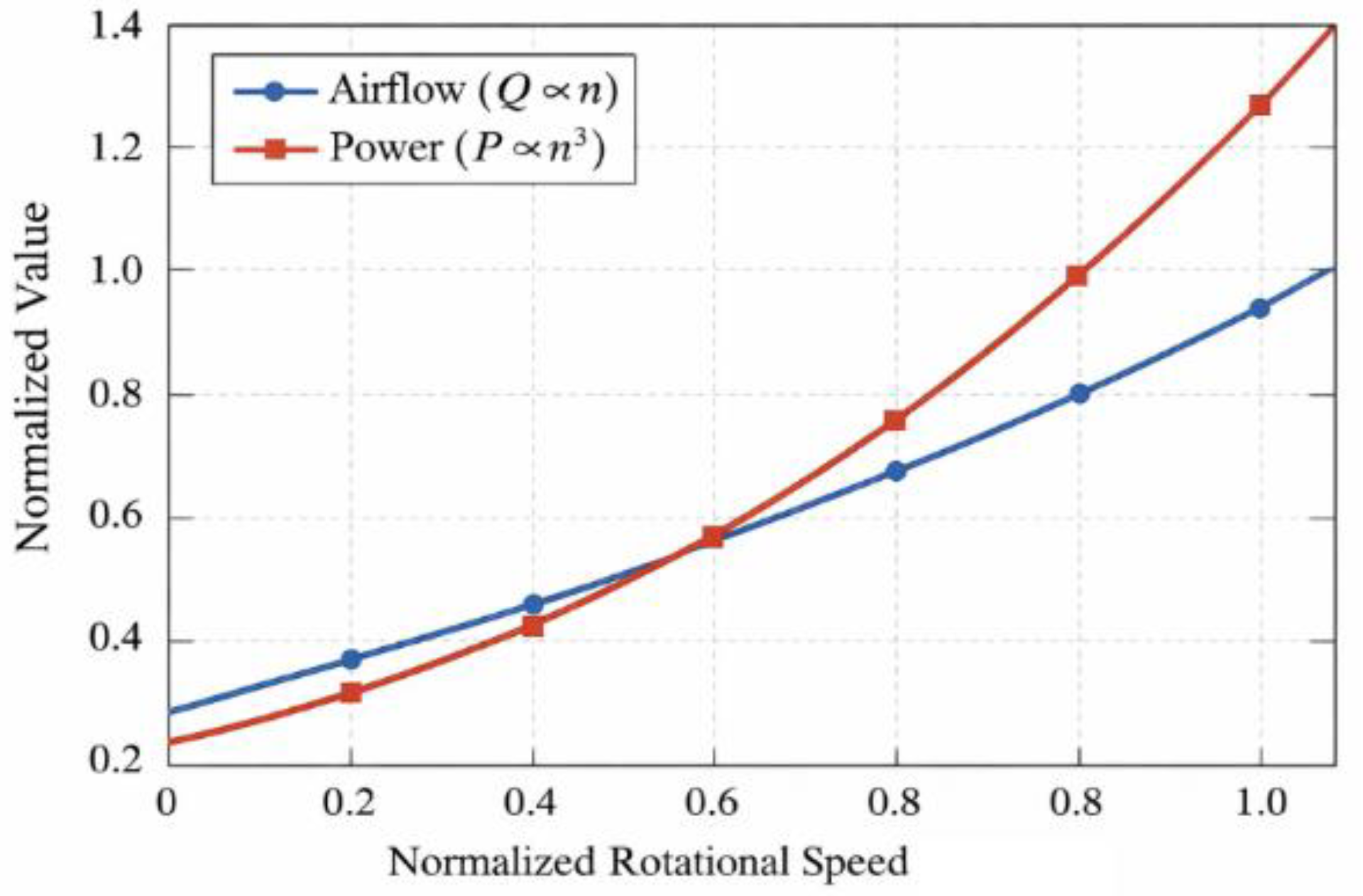
Figure 3.
Conceptual power flow and loss components in an induction motor, highlighting the slip dependent rotor copper loss mechanism.
Figure 3.
Conceptual power flow and loss components in an induction motor, highlighting the slip dependent rotor copper loss mechanism.
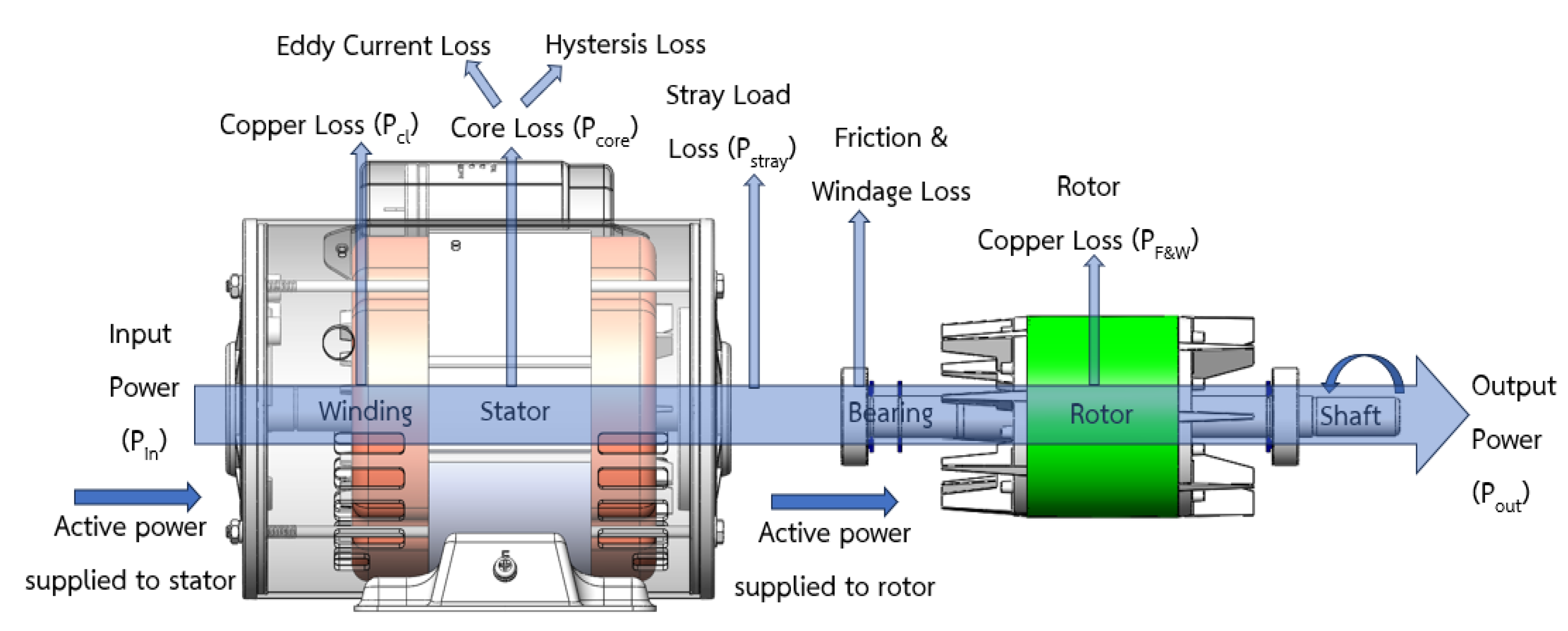
Figure 4.
Application for ventilation fans.
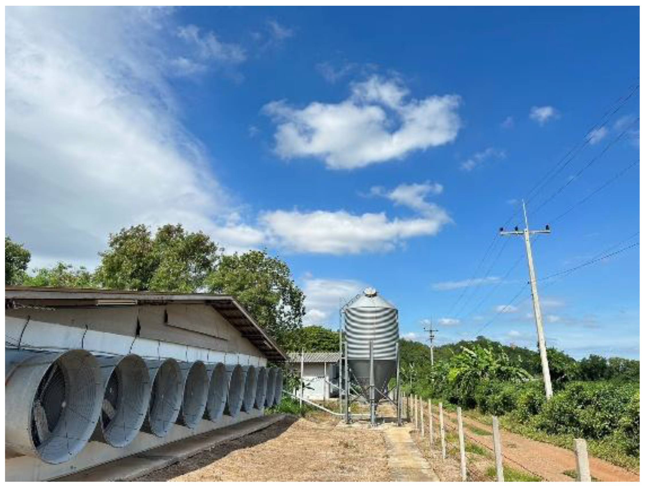
Figure 5.
Motor housing structure reused from the commercial induction motor platform in the converted PMSM design.
Figure 5.
Motor housing structure reused from the commercial induction motor platform in the converted PMSM design.
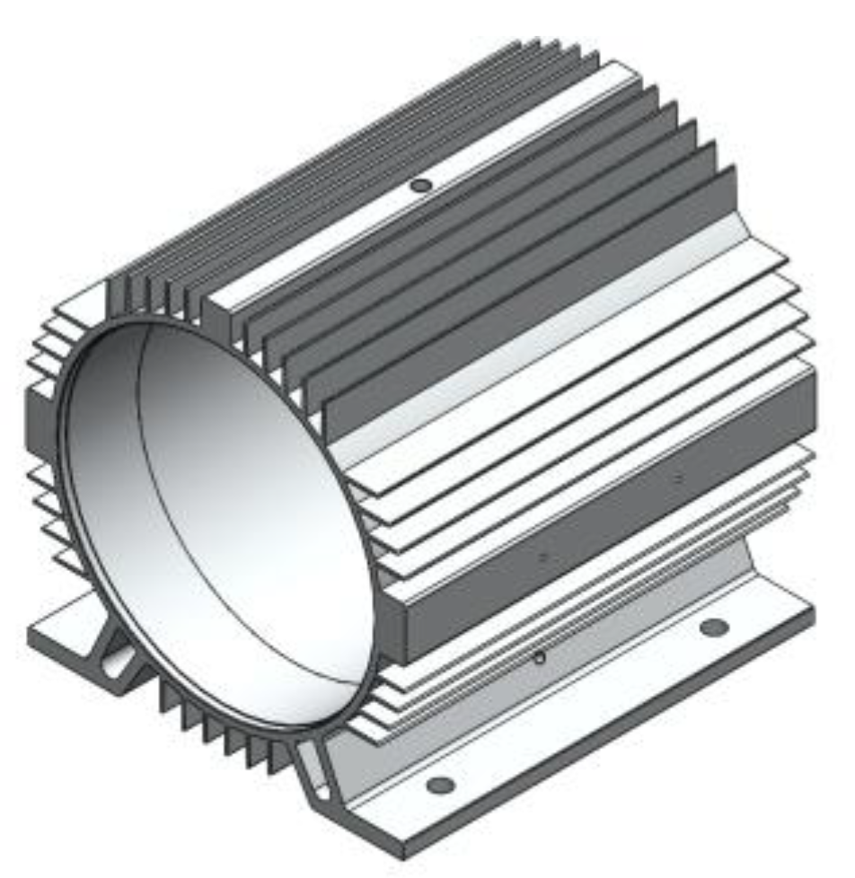
Figure 6.
Reused stator lamination geometry of the commercial induction motor platform (outer diameter 160 mm, inner diameter 100 mm, stack length 95 mm, 36 slots).
Figure 6.
Reused stator lamination geometry of the commercial induction motor platform (outer diameter 160 mm, inner diameter 100 mm, stack length 95 mm, 36 slots).
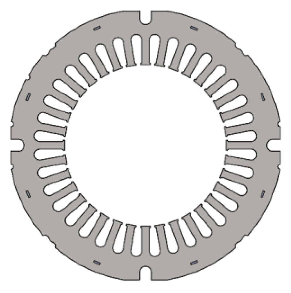
Figure 7.
Comparison of rotor structures: (a) squirrel cage rotor and (b) permanent magnet rotor.
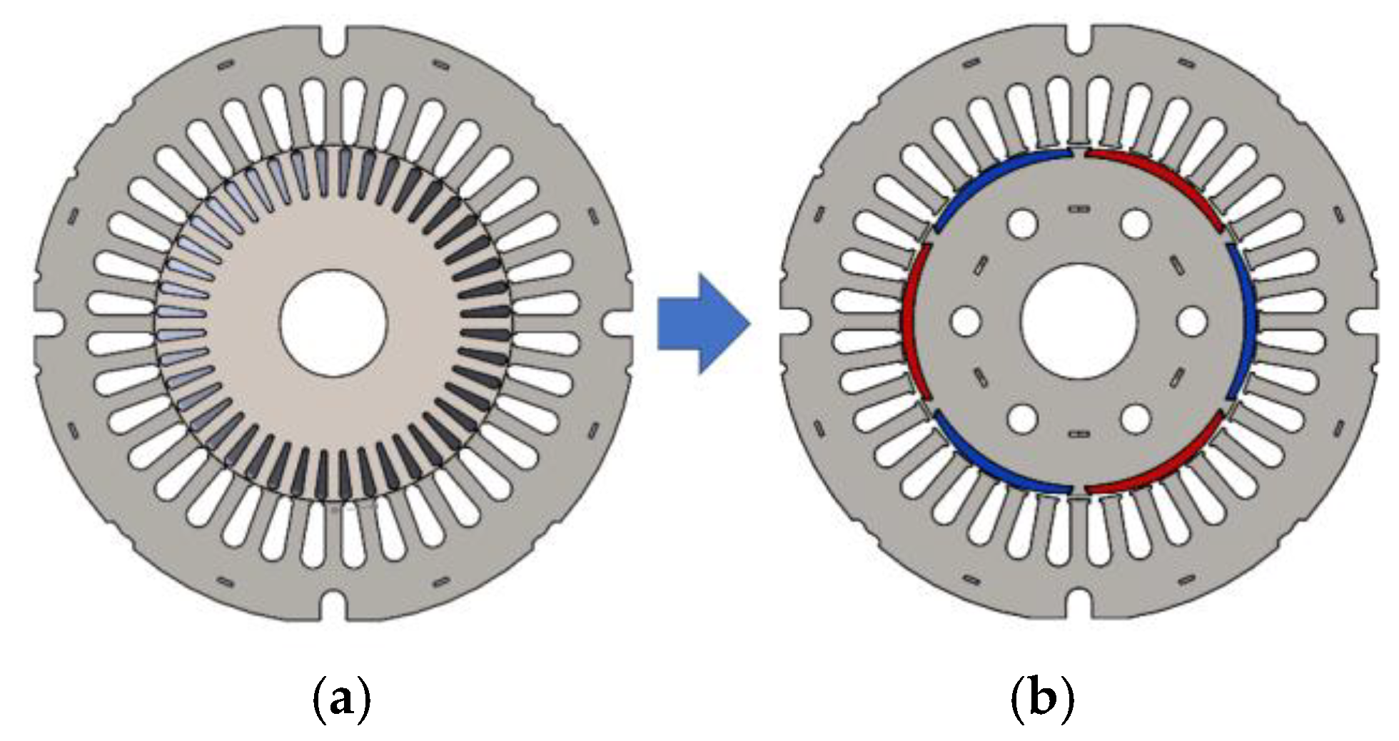
Figure 8.
Commercial inverter drive used for PMSM control in the experimental system.
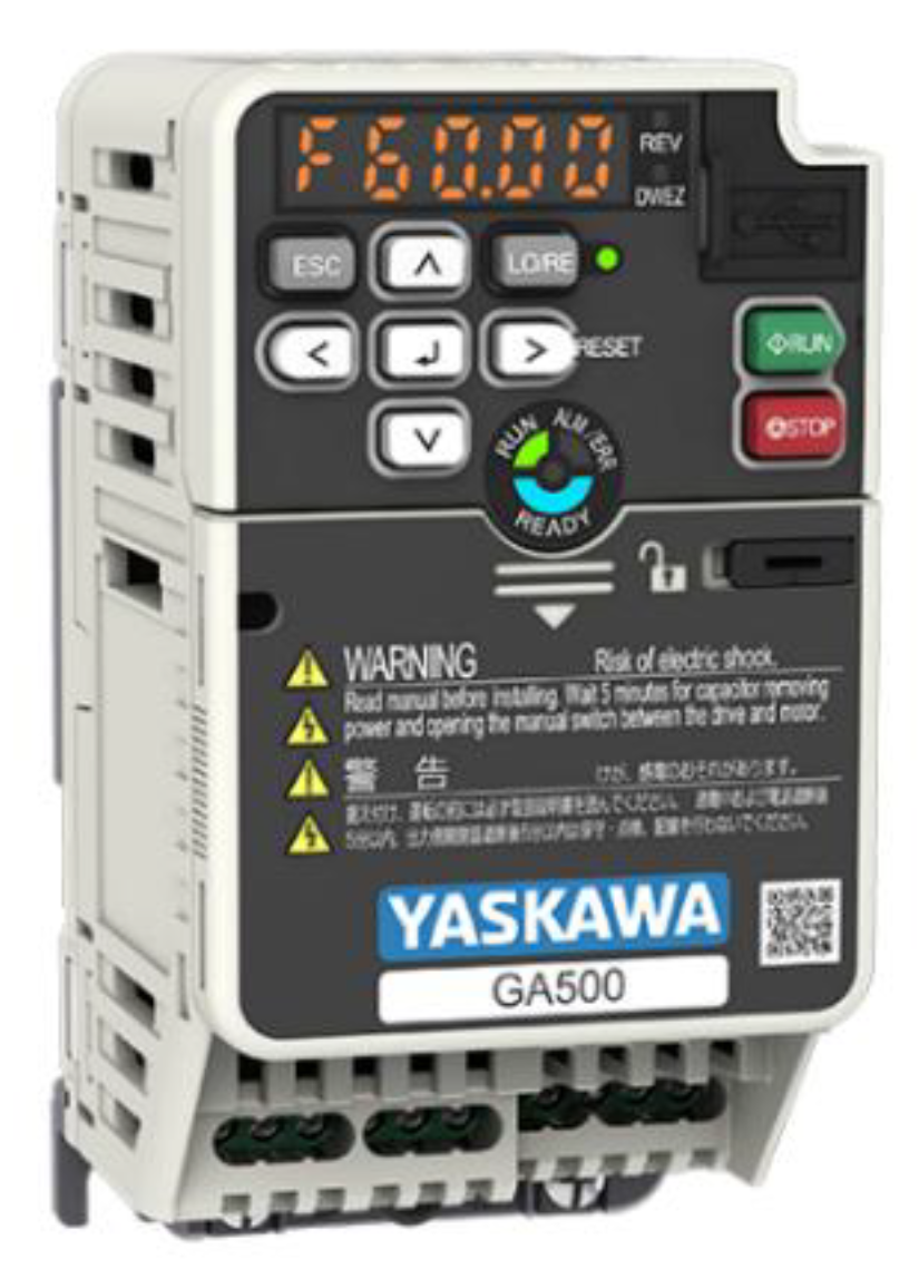
Figure 9.
Prototype fabrication of the converted PMSM: (a) stator winding implementation; (b) assembled PMSM prototype.
Figure 9.
Prototype fabrication of the converted PMSM: (a) stator winding implementation; (b) assembled PMSM prototype.
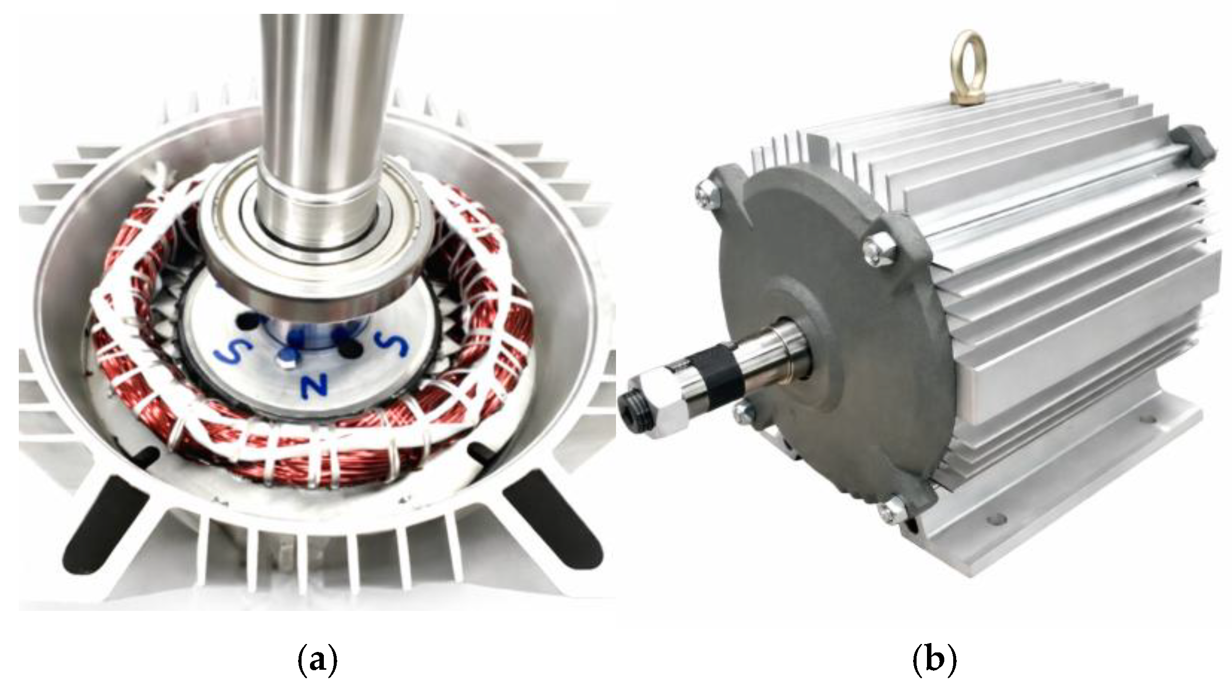
Figure 10.
Winding layout of the 6 pole, 36 slot stator.
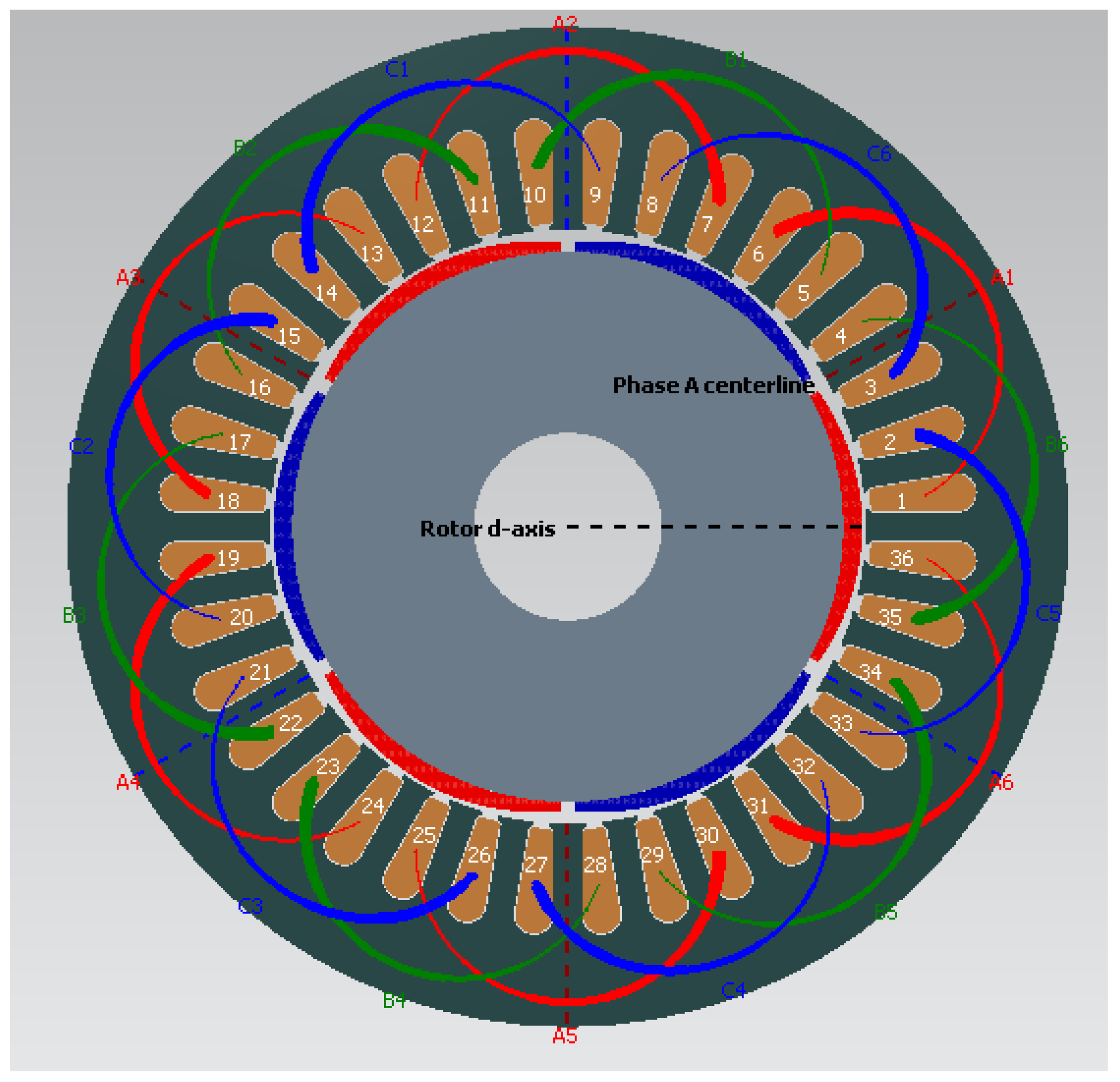
Figure 11.
Permanent-magnet dimensions: width 41 mm, length 97 mm, and thickness 2 mm.
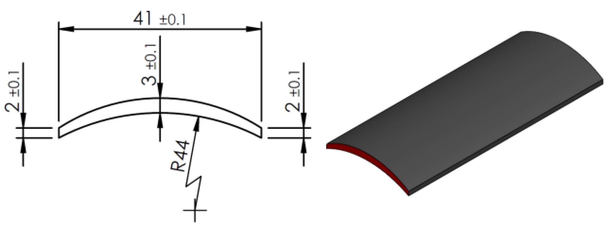
Figure 12.
Air gap length of 0.5 mm.
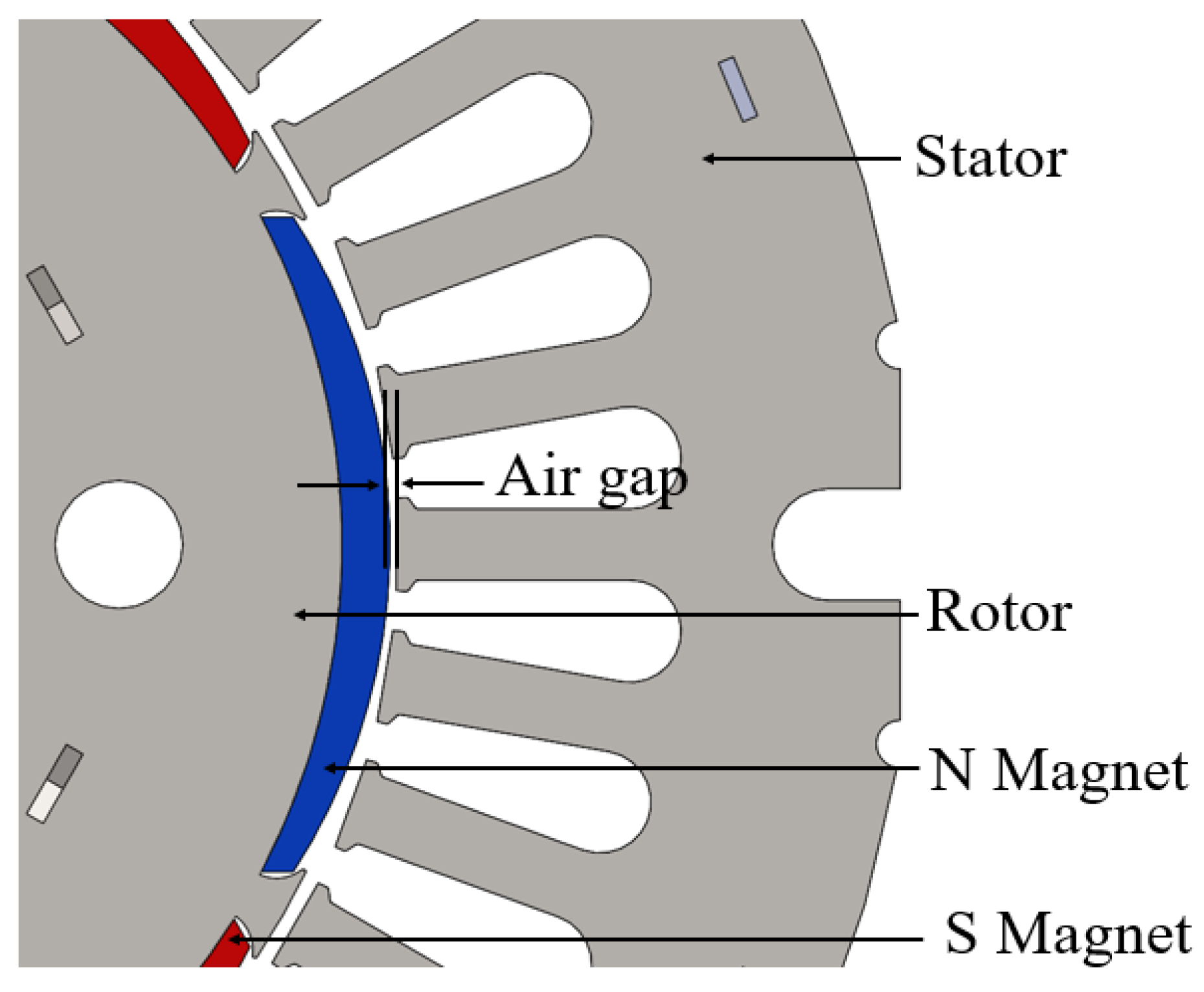
Figure 13.
Experimental setup for motor performance measurement: (a) power measurement instruments and control system; (b) PMSM prototype mounted on the dynamometer test bench; (c) Magtrol interface mounted on the test machine; (d) back EMF measurement.
Figure 13.
Experimental setup for motor performance measurement: (a) power measurement instruments and control system; (b) PMSM prototype mounted on the dynamometer test bench; (c) Magtrol interface mounted on the test machine; (d) back EMF measurement.
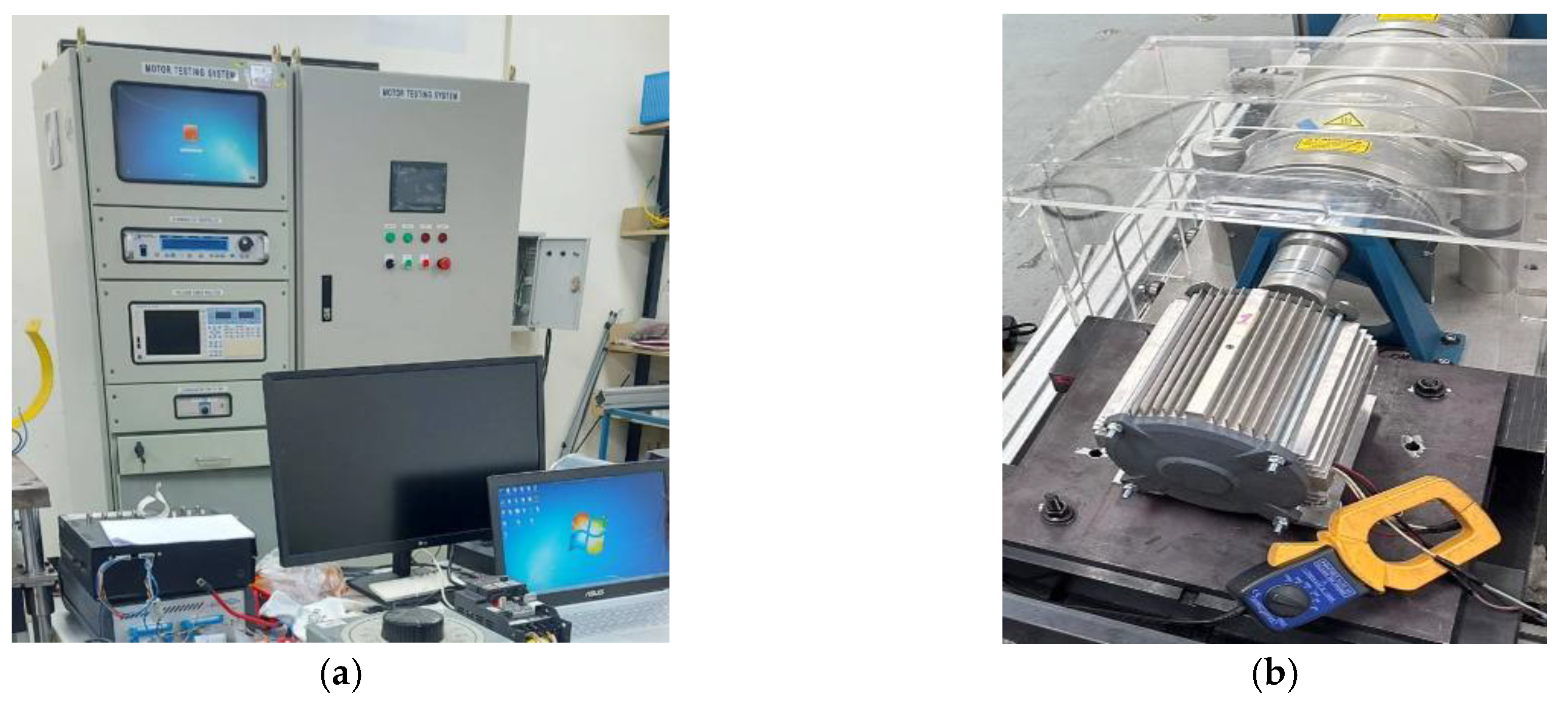
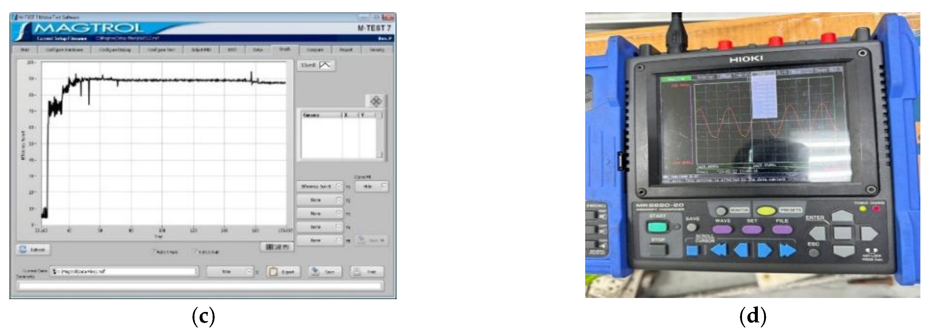
Figure 14.
Efficiency map of the converted PMSM prototype showing efficiency distribution as a function of motor speed and torque.
Figure 14.
Efficiency map of the converted PMSM prototype showing efficiency distribution as a function of motor speed and torque.
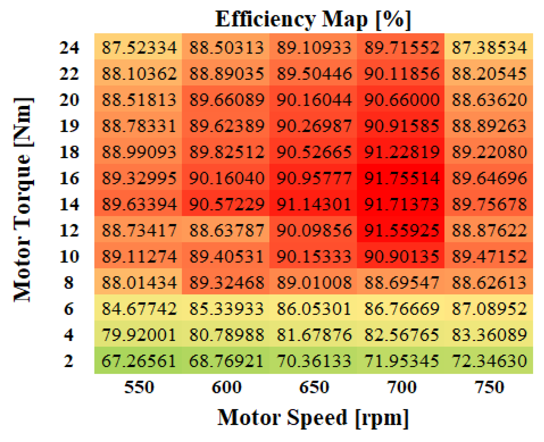
Figure 15.
Efficiency versus load.
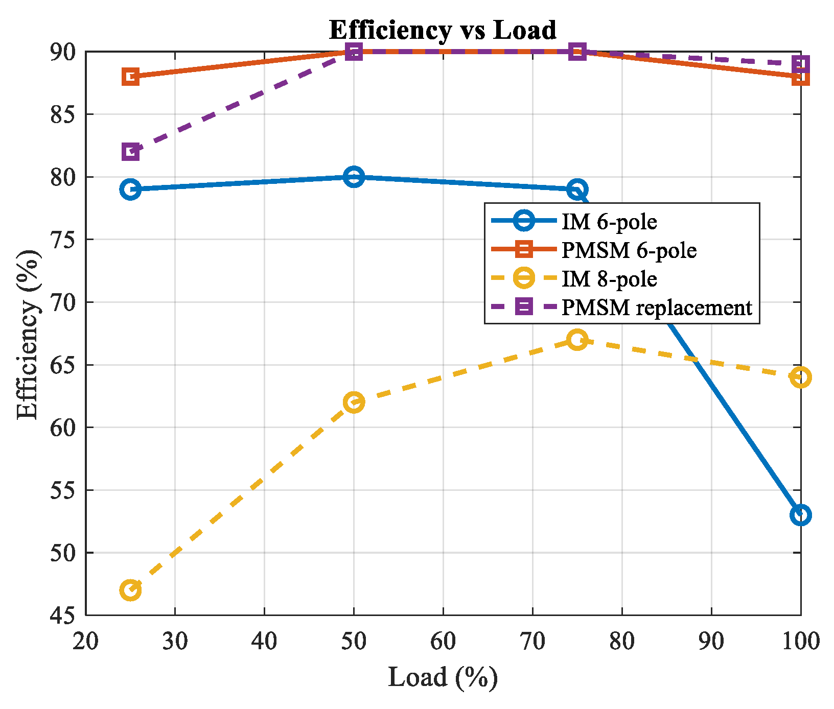
Figure 16.
Motor loss versus load.
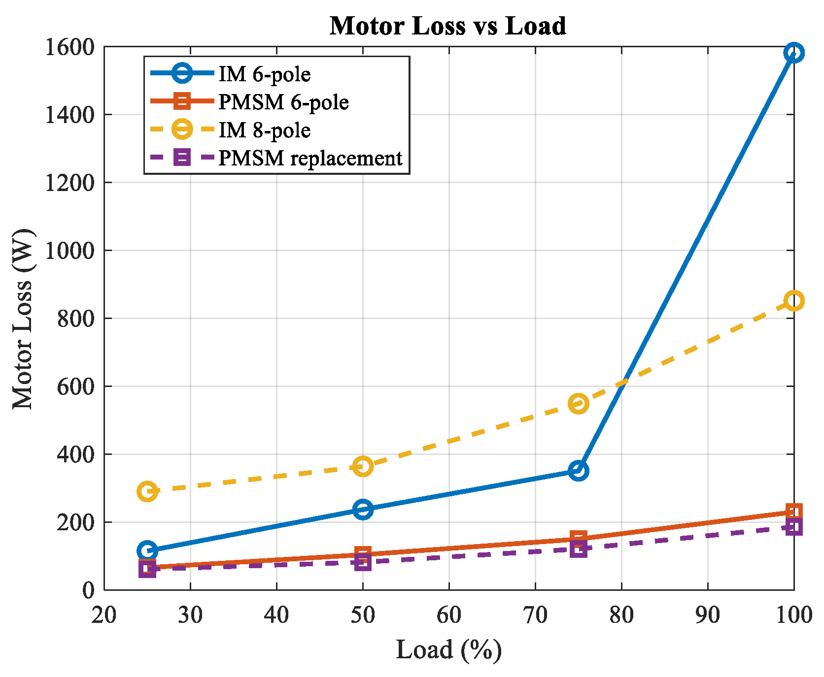
Figure 17.
Efficiency improvement of the PMSM relative to the induction motor.
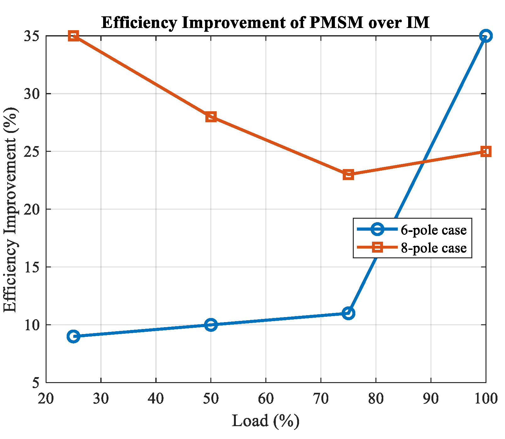
Figure 18.
Input power saving of the PMSM relative to the induction motor.
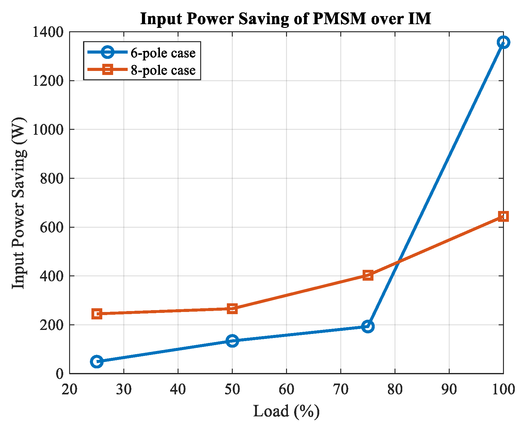
Figure 19.
Efficiency versus torque.
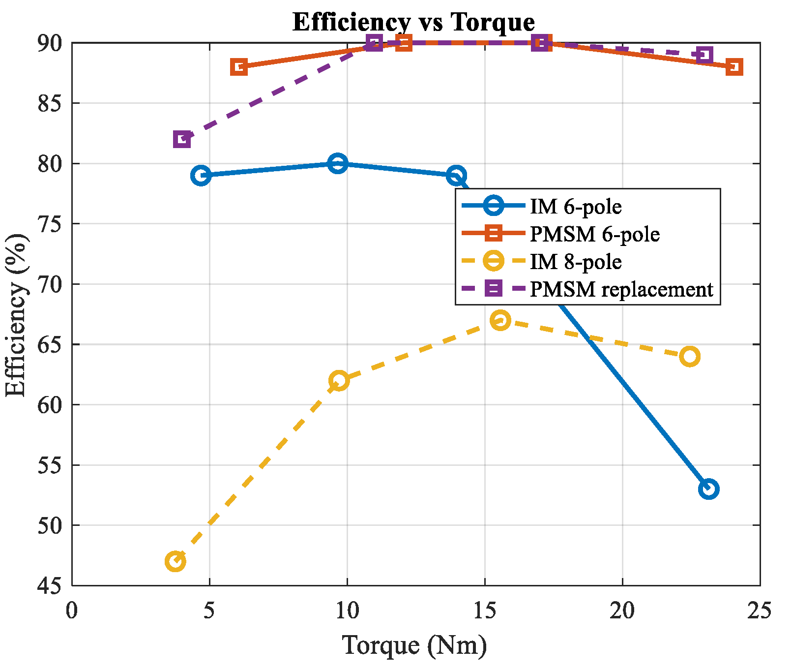

Table 1.
Design parameters of commercial induction motors and the converted PMSM prototype.
|
Motor Specification |
3-Phase IM Motor 6-pole |
3-Phase IM Motor 8-pole |
Proposed PMSM Motor 6-pole |
| Stator diameter (mm) | 160 | 190 | 160 |
| Rotor diameter (mm) | 100 | 120 | 100 |
| Stack height (mm) | 140 | 110 | 95 |
| Rotor type | Squirrel cage | Squirrel cage | Surface PM |
| Silicon steel grade | 50A1300 | 50A1300 | 50A600 |
| Winding layout | Distributed | Distributed | Distributed |
| Magnet quantity (unit) | - | - | 6 |
| Inverter drive | No | No | Yes |
Table 2.
Performance comparison of commercial induction motors and the proposed PMSM prototype.
|
Motor Specification |
3-Phase IM Motor 6 pole |
3-Phase IM Motor 8 pole |
Proposed PMSM Motor 6 pole |
Proposed PMSM Motor 6 pole |
| Power output (kW) | 1.54 | 1.80 | 1.56 | 1.80 |
| Voltage (V) | 380 | 380 | 380 | 380 |
| Frequency (Hz) | 50 | 50 | 50 | 50 |
| Full load current (A) | 4.87 | 7.10 | 2.94 | 5.50 |
| Power input (kW) | 2.39 | 3.43 | 1.74 | 2.03 |
| Full load speed (rpm) | 655 | 750 | 650 | 750 |
| Slip (%) | 13 | 25 | 0 | 0 |
| Full load efficiency (%) | 64 | 53 | 89 | 88 |
| Torque (Nm.) | 22.45 | 23.14 | 22.99 | 24.07 |
Table 3.
Measured performance data of the 6 pole induction motor and converted PMSM prototype.
|
Load (%) |
Motor |
Current (A) |
P_in (W) |
Torque (Nm.) |
Speed (rpm) |
P_out (W) |
Efficiency (%) |
| 100 | IM 6P | 7.1 | 3387 | 23.14 | 760 | 1805 | 53 |
| 100 | PMSM | 5.5 | 2030 | 24.07 | 750 | 1800 | 88 |
| 75 | IM 6P | 3.3 | 1685 | 13.97 | 930 | 1334 | 79 |
| 75 | PMSM | 4.3 | 1492 | 17.15 | 748 | 1342 | 90 |
| 50 | IM 6P | 2.4 | 1185 | 9.66 | 957 | 948 | 80 |
| 50 | PMSM | 3.1 | 1051 | 12.06 | 750 | 947 | 90 |
| 25 | IM 6P | 1.6 | 592 | 4.69 | 980 | 472 | 79 |
| 25 | PMSM | 1.7 | 543 | 6.07 | 750 | 477 | 88 |
Table 4.
Measured performance data of the 8 pole induction motor and converted PMSM prototype.
|
Load (%) |
Motor |
Current (A) |
P_in (W) |
Torque (Nm.) |
Speed (rpm) |
P_out (W) |
Efficiency (%) |
| 100 | IM 8P | 4.9 | 2390 | 22.45 | 655 | 1538 | 64 |
| 100 | PMSM | 2.9 | 1746 | 22.99 | 650 | 1560 | 89 |
| 75 | IM 8P | 3.9 | 1676 | 15.57 | 691 | 1127 | 67 |
| 75 | PMSM | 2.3 | 1273 | 16.99 | 650 | 1152 | 90 |
| 50 | IM 8P | 3.2 | 1091 | 9.71 | 715 | 727 | 62 |
| 50 | PMSM | 1.6 | 825 | 10.99 | 650 | 743 | 90 |
| 25 | IM 8P | 2.9 | 578 | 3.76 | 735 | 288 | 47 |
| 25 | PMSM | 1.0 | 333 | 4.00 | 650 | 272 | 82 |
Disclaimer/Publisher’s Note: The statements, opinions and data contained in all publications are solely those of the individual author(s) and contributor(s) and not of MDPI and/or the editor(s). MDPI and/or the editor(s) disclaim responsibility for any injury to people or property resulting from any ideas, methods, instructions or products referred to in the content. |
© 2026 by the authors. Licensee MDPI, Basel, Switzerland. This article is an open access article distributed under the terms and conditions of the Creative Commons Attribution (CC BY) license (http://creativecommons.org/licenses/by/4.0/).
Copyright: This open access article is published under a Creative Commons CC BY 4.0 license, which permit the free download, distribution, and reuse, provided that the author and preprint are cited in any reuse.