

Submitted:
07 March 2026
Posted:
10 March 2026
You are already at the latest version
Abstract
In this study we show that on the basis of simple crystallographic rules applied to the sphere-in-contact model/theorem that we can predict that under ambient conditions of pressure and temperature that the most dense and stable form of lithium in GICs is LiC6 and that two distinct form of LiC8 are possible. We find that other empirical formulas such as MC2, MC3 and M3C8 are possible based on crystallography, but not stable based on intercalate repulsions. The results are based on the unit cell description of GICs with the sphere-in-contact model/theorem that is used to model the intercalation of an arbitrary atom within the AαAα stacking1 of two graphene layers in GICs. We calculate the density and the packing fraction of these materials. This approach offers a simple description of the structure of GICs in which the unit cell can be defined and the diffusion of ions can be estimated on the basis of the void space in these materials. We anticipate that this simple description of GIC will be useful for the rational design of new graphite-based materials that can find use in various energy storage applications such as ion-based batteries but also as an educational tool in which university level education in materials and surface chemistry is directly connected to basic laws in chemistry, physics and mathematics.
Keywords:
graphite intercalation compounds
; GIC
; Li-ion batteries
; unit cell
; packing fraction
; density
; ion diffusion
1. Introduction
Li-ion batteries are powering smartphones, laptops, electric vehicles and other electronic devices are now broadly used in many commercial applications2. Their invention is credited to John B. Goodenough, M. Stanley Whittingham and Akira Yoshino in 2019 with the Noble price in chemistry “for the development of lithium-ion batteries”3-5. The battery anode in Li-ion batteries is composed of graphite which stores the Li+ cations during the charging cycle of the battery6. The Li+ diffuse between the basal planes of graphite forming structures that resemble graphite intercalation compounds (GICs)7. The exact mechanism for the diffusion and storage of Li+ cations in GICs is not well understood and various proposals for this have been made8. In battery materials the rate of charge-discharge cycles is a critical component in the design of battery materials and setups that require less time to be charged or discharged are being developed9. This rate is associated to the rate of diffusion of Li+ cations between the graphene layers of graphite2. Additionally, studies have since investigated the electrochemical properties of graphite and alternative anode materials to improve rate capabilities, thermal stability, and overall energy density; a pursuit driven by the ever-rising demand for longer-lasting, higher-capacity batteries in consumer electronics and electric vehicles10, 11. We therefore in this study have used sphere-in-contact models of GICs that have an AαAα stacking sequence, to study the diffusion of Li+ cations for GIC having various empirical formulas. These empirical formulas where given by the placement of intercalate atoms on the basal plane of graphene in a configuration that minimizes the Coulombic repulsive energy between cations. These in general are intercalate structures that are hexagonally symmetric and place the intercalate atoms at their largest possible distances, as we have recently shown is also the arrangement that monoatomic adsorbates attain when adsorbed on close-packed surfaces of metals12.
The sphere-in-contact model/theorem is a molecular and materials model where the atoms have their atomic radius (e.g. ionic radius, metallic and covalent). This results in spheres that are in contact for structures that have either covalent, ionic or metallic bonding and these structures show in an improved way the electron cloud volume of an atom, an ion or even a metallic atom. We have previously shown that this model can better describe the structure of carbon materials (e.g. graphene, graphite, carbon nanotube, fullerene) as it correctly shows the void space in the structure. 13 We have also used sphere-in-contact models to study the position of close packed nanoparticles on metal surfaces 14 and prepared miniature molecular models of heterogeneous catalysts, supported metal nanoparticles and organic molecules. 15 We have also used it in the elucidation of the cap structure of (3,3)-, (4,4)- and (5,5)-SWCNT where physical sphere-in-contact models were constructed to understand the geometry of the spherical cap. 16 Also as electromagnetic radiation interacts with the electron density cloud of atoms in sphere-in-contact models was applied to model the structure of an X-ray filter in which graphite had the rhombohedral structure. 17 Recently we have used such models to study diffusion mechanisms of adsorbates on close-packed metallic surfaces.12 So the use of the sphere-in-contact model is useful when analytical solutions of the distances between charged surfaces of atoms is desirable. These inter-surface distances can be used to evaluate the repulsive interaction energy between adsorbates and dopants in surface and materials chemistry using the Coulomb’s law, where the partial charges are not centred at the nucleus of the atoms, but rather on the surface of a sphere that has the atomic radius of the atom. The evaluation of Coulomb terms is computationally inexpensive and a method that can show clearly why certain dopant geometries or adsorbate structures that are symmetric are preferred as they reduce the interatomic repulsive energy term. It also useful as an educational tool as it directly translates concepts that students are taught in secondary school, such as basic laws of physics (i.e. Coulomb’s law), mathematics (e.g. trigonometry, geometry) and the existence of partial charges in polar covalent bonds to structures of doped materials and ordering of adsorbates on surfaces of metals and 2D layered materials (e.g. graphite intercalation compounds).
1.1. Computational Studies of GICs as Battery Materials
Computational methods have been applied extensively in order to investigate the structural, energetic, and transport properties of graphite intercalation compounds (GICs), offering insight into lithium staging behaviour in layered materials like graphite, interlayer interactions, and the dynamics of ion diffusion. Density functional theory (DFT) calculations that account for van der Waals interactions have demonstrated that the stability of lithium-intercalated graphite structures, such as LiC6 and LiC12 configurations, sensitively depends on intercalant type, charge density, and interlayer spacing18, 19. These studies show that ionic size and the charge distribution of alkali metals influence both the spacing between graphite layers and the staging structure, which impact lithium-ion (Li+) mobility together. Analysis of diffusion barriers has shown that lithium tends to move more easily along flat planes of graphite rather than between them, following paths that minimize repulsive interactions consistent with geometric models20. First-principles modelling of staged compounds has further helped to clarify how structural changes occur with shifts in ion concentration, emphasizing the energetic trade-offs between maintaining stage stability and transport efficiency21. Molecular-scale simulations of graphite-electrolyte interfaces also suggest that solvent molecules and interfacial structure influences how easily ions move into the material and how likely the graphite layers respond and separate, with size and polarity effects closely linked to the spacing and arrangement of the graphite layers22, 23. These findings support the use of models that are more spatially focused such as the sphere-in-contact model/theorem, which helps visualize the space between atoms and offers an intuitive way to understand how 3D-structure affects ion movement in such layered carbon materials.
1.2. Empirical Formula of Various GIC’s Using the Sphere-in-Contact Theorem
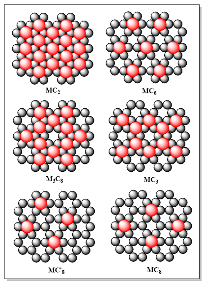
We have explored various possibilities for GIC’s using the sphere-in-contact theorem to models these materials. These models were designed based on the assumption that the intercalates atoms will have some partial positive charge on their atoms, due to charge transfer to the graphene layers. Therefore these structures have configurations that maximise the distances of the intercalates, in order to reduce the repulsive interactions, and therefore enhance the stability of the GIC. The partial charge sign in this treatment of repulsive intercalate interactions does not effect the energetic trends found for the various GIC as a function of intercalate concentration. With the use of this approach we find some intercalate geometries that are depicted in Figure 1, which shows the position of the intercalate (red atom) on the basal plane of graphene. The second graphene layer is not shown for better clarity but we assume an AαAα stacking sequence of the graphene layers, which is known to be the stacking sequence in most GICs.1
Having done this exploration of possible GICs we find that the empirical formula possible are MC2, MC6, M3C8, MC3 and MC8 although other less dense GIC are also possible. These would not be of considerable interest as the charge carrier density in such hypothetical GICs would not be high and therefore their application in ion-battery materials would not be of practical use, as such materials would not have large charge capacities. Therefore we consider here only the aforementioned empirical formulas that are shown in Figure 1.
1.3. Definition of Unit Cell in GICs
In this section we define the unit cell of the various GICs shown in Figure 1. On the basis of simple trigonometric and geometric rules we can calculate the unit cell parameters in terms of three angles (i.e. α, β, γ) and three unit cell vectors (i.e. a, b, c). The angles of the lateral unit cell are depicted in Figure 2 along with the various empirical formulas found.
In the calculation of the empirical formula we make use of the following basic geometric rules:
- a)
- An atom at the corner of the unit cell will have 1/8 of its mass within the unit cell if the unit cell angles are all 90°.
- b)
- An atom at the corner of the unit cell which has an angle φ and the other two 90°, will have φ / 720° of its mass within the unit cell.
- c)
- An atom at the edge of the unit cell will have ¼ of its mass within the unit cell is the unit cell angles are all 90°.
- d)
- An atom at the edge of the unit cell where one of the angle is φ and the other two 90°, will have φ / 360° of its mass within the unit cell.
- e)
- An atom at the side of the unit cell will have ½ of its mass within the unit cell.
- f)
- An atom within the unit cell will have an equivalent of one atom in the unit cell.
Using these rules we derive the various empirical formulas shown in Figure 2 making the assumption that the intercalates will always reside in the center of the hexagonal ring on the graphene layers, due to the higher coordination number at these positions, which reduces the charge on the intercalate and therefore the GIC would be more stable. Also the configuration of intercalates is such that there is a maximum average distance between them, which would minimise the repulsive energy between intercalates and therefore would be a lower energy configuration. This would also presumably be a preferred configuration when the ion-battery material is not in charged state.
1.4. Calculation of the Density of Various GIC’s Within the Sphere-in-Contact Theorem
The density of an arbitrary GIC using the sphere-in-contact theorem can be defined as
The volume of any unit cell in a material can be calculated from the volume of the triclinic unit system which is given from
where , and are the lattice vectors and and the angles between the lattice vectors as shown in Figure 3.
Here the primitive unit cell has rhombus base and height c. If we start from the volume of the triclinic unit cell the unit cell volume is given by,
where and and is the height of the unit cell of the GIC, which is given by,
The trigonometric and geometric derivation of the height of the unit cell is given in section 1.5.
The density of the GIC is given by combining Eqns. 1, 3 and 4 and is given by
where and is the number of lithium and carbon atoms within the unit cell of the GIC, and are the atomic masses of Li and C, respectively, and and are the atomic radii of the lithium ion and the covalent radius of carbon in graphite, respectively. Noteworthy, is that this equation is not limited to Li-ion GICs but can be used for any momoatomic (e.g. Li, Na, K, Rb, Cs) intercalates between graphite layers.
We have used the cationic radius of lithium to calculate the density of such GIC may depend on the charged state of the GIC. We expect that for the intercalate atoms to be mobile in the presence of an external electric field, that is parallel the graphite basal plane that these are cationic lithium species, mainly due to their smaller radius and charge compared to the atomic radius of a neutral lithium intercalates, are the mobile species. It is also conceivable that not all intercalates are in the same charged state during the charging/discharging of such materials. So the radius of the intercalate can be between the atomic radius of lithium and the ionic radius of lithium and that the charged state of the intercalate atoms mainly affects the interlayer distance, and that the carbon hexagonal framework is affected to a smaller extent, as the interatomic distances in that are mainly determined by the sigma covalent framework, that does not participate in the bonding with the intercalates. Based on MP2 calculations of the lithium cation between two benzene rings we observe little variations of the C-C bond lengths, which is not affected by the formation of the ion-π bond between lithium cations and the conjugated π-clouds in cyclic carbon rings.
1.5. Height of Unit Cell Using the Sphere-in-Contact Model/Theorem for Lithium GICs
Figure 4 shows the top view and side view of an arbitrary GIC with AαAα stacking sequence, where the intercalates are in the center of the hexagonal ring of graphite and in which the height of the unit cell is shown (c). With the use of Pythagoras’ theorem and the dimensions of the triangle shown in Figure 4, given as a function of the radius of the carbon atom and the radius of a lithium cation, we are able to calculate the height of the unit cell which is given by c. We only consider GIC models where the interlayer spacing between the graphene layers is that of LiC6, which has been found to be a stable form of lithium graphite intercalation compound under ambient conditions of pressure and temperature. We expect this assumption to be valid if the intercalation of lithium atoms is maximum when there is one lithium atom per hexagonal ring of graphite and every layer of graphite is fully saturated with lithium atoms, but is has been previously confirmed via in situ neutron diffraction that the lattice dilation during charging of lithium ion batteries is only 4%24, which corresponded to an empirical formula of LiC6. However, in this study we explore some higher in concentration Li+ phases in GICs as we expect based one purely geometric considerations that such higher in density lithium phases in graphite would also result in lattice dilation of the order of 4%. This is based on a number of experimental and computational studies that suggest that such superdense phases of lithium are possible to an empirical formula of LiC2, which is the highest density phase considered in this study. For example, XPS studies with the use of piston-cylinder high-pressure chamber indicate that lithium intercalation to LiC2 causes insignificant changes in the chemical shifts of carbon atoms, consistent with the assumption made here that there is not a significant lattice dilation comparing LiC6 an LiC2 structures.25 Lithium overintercalation, beyond LiC6, has also been observed recently at ambient pressure, using static 7Li nuclear magnetic resonance (NMR).26 A very recent study that used ball milling to prepare LiC3 under ambient conditions found that this structure is also stable at ambient conditions.27 Noteworthy, the stability of the LiC3 phase was previously predicted on the basis of Density Functional Theory (DFT) calculations, in addition to the existence of a LiC2 phase which was found metastable.28
So the assumption of one Li+ per carbon ring is the maximum Li ion concentration that can be evaluated using the current approach within the sphere-in-contact theorem, and that the interlayer distance is the same for highly dense Li-ion GICs, as dense as LiC2 would result in a possible error of less than 4%, in the volume calculation of he unit cell, of these arbitrary GICs. We note here that although we explore these high density phases of lithium in graphite, such as LiC3 and LiC2, such high density phases could result in considerable clustering between lithium ions into metallic lithium clusters, under reducing conditions. Such metallic clusters for lithium have been observed via infrared spectroscopy of LiC4 and LiC2 29 and are potential pathways for the chemical and mechanical degradation of such lithium ion GICs, in ion-battery materials, under reducing conditions (i.e. excess of electrons within these materials).
1.6. Interlayer Distance in LiC6 and Radius of Li atoms Intercalated
There have been many crystallographic studies to accurately estimate the in interlayer spacing in LiC6 and the stacking sequence. Crystallography suggests that the stacking sequence is AαAα with an interlayer distance of 3.70 Å, based on the stable form of this GIC at ambient temperature and pressure, in samples that where prepared by annealing or under pressure, causing lithium to intercalate between the layers.1 This interlayer distance is also in agreement with a study that investigated it as a function of lithium intercalation obtaining the phase diagram of LixC6., where x was varied between 0 and 1.30 Additionally, LiC6 prepared by electrochemical reduction of natural graphite in a LiClO4 solution at 30 °C found a interlayer distance of 3.70 Å.31 This interlayer distance of 3.70 Å as well as the AαAα stacking sequence was also confirmed by neutron diffraction at various temperatures.32 This interlayer distance in comparison to that of hexagonal ABAB stacked graphite (3.354 Å)33 is 10.3% increased due to Li intercalation. We have therefore used this distance to estimate the radius of lithium ions within the sphere-in-contact model, when the carbon atoms have their covalent radius that corresponds to half a bond length of the C-C bond in graphite, 1.422 Å.33 With the use of Figure 4 we therefore calculated the radius of the lithium ions in the sphere-in-contact model to be 1.62 Å and that the covalent radius of carbon is 0.711 Å.
So in the next section we will perform calculations of the unit cell volume and the density in GICs using Eqn. 5 and the radius of intercalated lithium atoms, and the covalent radius for the carbon .
1.7. Density and Volume of the Unit Cell of GIC
So the volume of the unit cell of LiC6 is,
The GIC with the empirical formula LiC6 has one Li atom and six carbon atom per unit cell, so the density is given by
Where and are the mass of the lithium and carbon atoms which were calculated from the atomic masses of these atoms as taken from the IUPAC periodic table and are and . So the density of LiC6 is 2.25 g cm-3 which is in excellent agreement with the literature value of 2.21 g cm-3 based on XRD.1. This suggests that Li in LiC6 is not in a +1 charged state under ambient conditions and that the radius of Li in LiC6 is closer to the atomic (i.e. 12 coordinated metallic radius) radius of Li (1.5 Å)34 , rather than the ionic radius of Li+ (rCN4 = 0.59 Å, rCN6 = 0.76 Å, rCN8 = 0.92 Å)35 estimated from empirical analysis of interatomic distances in lithium oxides. This is an interesting result that is mainly associated with the property of lithium having a significantly larger radius than carbon which is associated to the smaller effective nuclear charge of lithium (Zeff) compared to carbon. Furthermore, it suggests that based on the atom radius of Li in the sphere-in-contact model that the most dense phase of lithium in graphite is LiC6 and that any further addition of Li to graphite, forming LiC2 and LiC3, which have been suggested as superdense phases of lithium atoms in GICs would result in a significant overlap of the electron densities of the lithium atoms, which would suggest a rather metallic 2D array of lithium atoms, rather than isolated lithium atoms. This is perhaps the reason that these superdense configurations of lithium atoms in GIC are not observed under ambient conditions and require mechanical compression or other extreme electrochemical conditions.
1.8. Packing Fraction of GIC and Diffusion Rate of Intercalates
From the packing fraction the available space for intercalate diffusion can be estimated. The void space fraction of the atoms in a unit cell is given as 1 minus the packing fraction. Therefore, the void space in a material correlates to the space available for atom/ion (i.e. intercalate) diffusion. This correlation can be made based on the fact that the lowest barrier for intercalate diffusion within the graphene sheets will be roughly the same for any density of intercalates between the layers as intercalates are hold by weaker interactions (e.g. ion-π interactions), compared to the stronger covalent C-C bonds within the graphene layers. This barrier is expected to be lower over the C-C bonds of the graphene layers, rather than over the C positions, as the coordination is greater when the adsorbate is directly on top of the covalent bonds, connecting the carbon atoms, which suggests a lower barrier for diffusion from the center of one hexagonal carbon ring to the centre of an adjacent hexagonal ring (see Figure 2). So the parameter that limits the diffusion in the case of GICs is not the barrier for diffusion but the available void space between the layers and the path that the ions follow during this diffusion, which also determines the capacity of the batteries. This is based on physical understanding of this material which suggest that the barrier of diffusion is very high, if there is already and intercalate in the adjacent hexagonal ring. We therefore suggest that the packing fraction using the sphere-in-contact model/theorem can used in materials design.
Although there are not any reported crystallographic structures for LiC10 there have been reports of GICs with empirical formula MC8. KC₈, RbC₈, and CsC₈ are known examples of GIC with this empirical formula36, which is a less dense phase of the intercalated atoms in graphite. This is perhaps associated with the atom radius of the intercalate as potassium (rK = 2.3 Å)34, rubidium (rRb = 2.5 Å)34 and caesium (rCs = 2.7 Å)34 which all have significantly larger radii than Li (rLi = 1.5 Å)34 and therefore are more stable at a larger separation, to prevent their transition to a 2D metallic state. This is in agreement with the interatomic distance of intercalates in the MC8 empirical formula in which the interatomic distance between intercalates is about 4.926 Å, and consequently the nearest surface-to-surface distance between intercalates is larger compared to the interatomic distance between intercalates in the MC6 structure which is about 4.266 Å. Therefore, the MC8 structure in the sphere-in-contact model will have smaller repulsion between the intercalated atoms and therefore, bulkier atoms can be accommodated between the layers, at relatively larger separations. The effect of the radius of these atoms on the interlayer distance in MC8 (dK = 5.35 Å)37, rubidium (dRb = 5.65 Å)37 and cesium (dCs = 5.94 Å) has been previously reported and is consistent with the trend of their atomic radius.37
Additionally, It is possible that a MC’8 structure can exist, as based on the interatomic distances between intercalates it would have intermediate stability to that of LiC6 and LiC8, but in this structure the interatomic distances in one direction are different than in the perpendicular direction, so 2D anisotropy would be expected and this structure would be more stable if it relaxes to MC8, based on the repulsive interactions between intercalates, as presented in section 1.9.
From the packing fraction the available space for intercalate diffusion can be estimated. The packing fraction is the % space occupied by the atoms in the unit cell of the material. Therefore, the packing fraction is inversely proportional to the available empty space (i.e. void space) in a material, which correlates to the space available for atom/ion (i.e. intercalate) diffusion. This correlation can be made based on evidence that the lowest barrier for intercalate diffusion within the graphene sheets will be roughly the same for any density of intercalates between the layers as intercalates are hold by weaker interactions (e.g. ion-π interactions), compared to the stronger covalent C-C bonds within the graphene layers. This barrier is expected to be lower over the C-C bonds of the graphene layer rather than over the C positions, as the coordination is greater when the adsorbate is directly on top of the covalent bonds, connecting the carbon atoms, which suggests a lower barrier for diffusion from the center of one hexagonal carbon ring to the centre of an adjacent hexagonal ring. The barrier for this diffusion has been previously estimated based on DFT calculations and it was found that for larger interlayer spacing this barrier reduces, increasing therefore the diffusion rate by 3-orders of magnitude, when the interlayer distance increases between 3.4 to 3.8 Å.38 In addition to this, it is conceivable that when the intercalates are in close proximity, that the barrier for ion diffusion will become exponentially high due to overlap of their electron density clouds, increasing the repulsive interactions, considerably. So this suggests that a more important factor for the diffusion of intercalates between graphite layers is the available void space, that is inversely proportional to the atomic packing fraction ( given by,
So we can approximate the diffusion rate parameter () is being proportional to the void space given by,
Apart from this purely geometric factor the relative charge transfer rate is directly proportional to the molar intercalate density (units: mol⋅cm-3) of the GIC which is given by the number of intercalate atoms in the unit cell divided by the volume of the unit cell and Avogadro’s number,
As the specific atomic radius of the intercalate atoms, for certain empirical formulas, results in considerable overlap of the electron cloud of the intercalate atoms, the void space in the sphere-in-contact model can also obtain negative values, when the intercalate density is very high (e.g. MC2). These structures have not been considered in the trends of intercalate diffusion rate. In this analysis we only consider the structures where the intercalate atoms do not overlap based on their atomic radius, which were found to be empirical formulas MC6, MC’8 and MC8, as the nearest neighbour interatomic intercalate distances were 4.266 Å, 4.524 Å and 4.524 Å, respectively. These interatomic distances are larger than two times the atomic radius of the intercalates which are 3.24 Å, 3.6 Å, 4.5 Å, 4.8 Å and 5.4 Å for Li, Na, K, Rb and Cs, respectively. Here, we find that for the other structures MC2 and M3C8 and MC3 the nearest neighbhour intercalate distance is only 2.262 Å which is less than two times the atomic radius of any of the group 1 intercalates. As such structure would result in a 2D metallic state of the intercalate atoms, and would render such a material not applicable in graphite-based battery materials. Based on this analysis we find that the trends of intercalate diffusion rate for the various group 1 elements having the MC6 empirical formula are,
LiC6=0.0154 > NaC6=0.0124 > KC6=0.0056 > RbC6=0.0044 > CsC6=0.0011
This trend suggests that lithium as an intercalate is the GIC that would have the largest diffusion rate of intercalate atoms, but interestingly a NaC6 GIC would only be 20% less efficient, based on geometric considerations. So we provide here a computationally very efficient way to screen various GIC’s for their efficiency as ion battery materials using as an input only the atomic radii of atoms in the GIC and using the sphere-in-contact model. For the empirical formulas of GIC considered we provide the value of the packing fraction in Table 3 that can be used to screen for the diffusion rate of any GIC with AαAα stacking given only the radius of the intercalates and carbon atoms.
) of the various empirical formulas of GIC using the sphere-in-contact model.
| Formula | Analytical equation of density | ηLi, GIC | ηNa, GIC | ηK, GIC | ηRb, GIC | ηCs, GIC |
| MC2 | 1.073 | 1.262 | 1.936 | 2.095 | 2.623 | |
| MC6 | 0.461 | 0.513 | 0.717 | 0.767 | 0.936 | |
| M3C8 | 0.843 | 0.981 | 1.479 | 2.130 | 1.991 | |
| MC3 | 0.383 | 0.444 | 0.663 | 0.716 | 0.890 | |
| MC’8 | 0.385 | 0.419 | 0.565 | 0.602 | 0.725 | |
| MC8 | 0.385 | 0.419 | 0.565 | 0.602 | 0.725 |
1.9. Calculation of the Interatomic Repulsive Energy (Unet) Between Intercalates to Assess the Stability of an Arbitrary GIC
To calculate the interaction between intercalates we have used a supercell approach for the various GICs in Figure 1, shown in Figure 5. We also assumed that the interactions between intercalates are up to the 8th nearest neighbour, which is about 8 Å, depending on the atomic radius of the intercalate. This assumption is valid as there will be significant screening of the partial charges on the surface of the atoms by the surrounding electron clouds, of nearby intercalate atoms. We have counted all 8 nearest neighbour interactions (i.e. di, where i = 1, 2, 3, 4, 5, 6, 7, 8) of the various configurations shown in Figure 5, which are shown in Table 1. We then used the following trigonometric and geometric derivation to calculate the repulsive interaction between partial point charges, at the nearest distance between the intercalate spheres. A similar equation was used to calculate the repulsive interaction between adsorbates on HCP and FCC, metal surfaces [Ref, preprint]. This equation is a summation of all the pairwise interactions, up to the 8th nearest neighbour intercalates and we assume that the partial charge on the surface of the intercalate is constant, and does not depend on the interactions between the intercalate (which would generate a local electric field), but only depends on the coordination number (CN) that the intercalate has with the graphene layer (i.e. the contact points of the intercalate sphere with the carbon atoms). Since the intercalates in all GIC’s studied in this study reside at the middle of the hexagon, in each carbon ring, and the stacking of the layers is AαAα, we can calculate the internal energy of this GIC model, depending on the saturation with lithium ions, during charging and discharging of the battery material. The coordination number of the intercalate is 12, as there are 6 carbon atoms in the first layer and 6 carbon atoms in the second layer, that are in direct contact with the intercalate. As lithium is a group 1 element and it tends to loose one electron to become more stable, the charge on each lithium will be +1. But since some of this electronic charge of the ionised electron, is charge transferred to the carbon rings in direct contact with the intercalate, and then from a π-ion bond, therefore the partial charge on the intercalate will only be a fraction of +1. Perhaps, we can assume that it will be +1/12 e because the coordination number of the intercalate is 12. Here we note that the absolute value of the partial charge on the intercalate surface is not a critical parameter in the sphere-in-contact model/theorem, in order to get the trends of the interactions between intercalates, in the various GICs. So we used a partial charge of +0.08 e and +0.16 e (this is a positive partial charge) gives us an indication of the repulsive interaction energy trends between intercalates in the various GICs. This provides a trigonometric equation that quantifies the stability of the various GICs and can be used to assess the internal energy (Unet) associated to various GICs, in a charged state, by changing the partial charge on the intercalates. This equation has dependent variables the atomic radius of the carbon atom () and the intercalate () and the partial charge on the intercalate surface (). These for LixCy GICs are and , respectively.
The distances between the intercalates are given by the following trigonometric equations. These are as a function of the atomic radius of the carbon atom and the atomic radius of the intercalate. So they can be applied to any GIC and are,
The interaction energy can be calculated by the pairwise summation using Coulombic terms given by,
where = 8.98755 x 10⁹ Nm2C-2, e = 1.60217 x 10⁻¹⁹ C, rLi = 1.52 x 10⁻¹⁰ m, rC = 0.709 x 10⁻¹⁰ m and . So for partial charges on the intercalates of 0.08 e, δ = 0.128 x 10⁻¹⁹ C this formula becomes
and for partial charges of the intercalates of 0.16 e, δ = 0.256 x 10⁻¹⁹ C
To establish an initial estimate of the pairwise sphere–sphere interactions, 2 researchers performed independent manual counts (i.e. using the pen and paper approach) using the structural image from Figure 5. Distances were approximated by comparing the spacing between spheres relative to known lattice features. Both sets of manual counts were recorded in a separate table, allowing us to compare consistency across independent observers and identifying the counts that had to be repeated, to achieve agreement between the 2 observers.
The centre of each sphere was identified and the distance of adjacent spheres was estimated based on the length of the C-C bond, the vertical and horizontal width of the benzene ring and whether the distance vector was on one of the crystallographic lattice vector or offset by one hexagonal ring, of the graphite layer. So with the use of these lattice features we were able to get very accurate counts of the pairwise interactions in combination with the use of a large supercell, to ensure that the repulsive energy of interaction between intercalates is as accurate as needed to be able to estimate the relative trend of stability in the these GIC’s, and its nearest neighbours were determined based on perceived based on nearest neighbour perceived surface-to-surface proximity.
With this approach we have listed these counts in Table 4 along with the corresponding repulsive interaction energy for two partial charge values. The partial charges used on the intercalate where 0.08 e (i.e. Unet, δ = +0.08e ) and 0.16 e (Unet, δ = +0.16e). We also attempted counting pairwise interactions using an image analysis software that extracted the centroid coordinates of the sphere in the images in Figure 5 and the sorted the distance between centroid cartesian coordinate with a computer script. But these counts were not found to be correct in most cases and therefore are not listed here.
Based on Table 4 we can observe that the relative stability trends of the various GIC do not depend on the amount of partial charge on the intercalates. We also observe that LiC6, LiC’8 and LiC8 are considerably more stable by almost one order to magnitude in kJ mol-1 than the higher intercalate density GIC’s.
So the trends in relative internal energy of the various GIC found is
LiC’8 < LiC8 < LiC6 < LiC3 < Li3C8 < LiC2
Here we not the stability trend calculated using the sphere-in-contact model is very reliable as we found that the number of pairwise interactions considered by only considering a two-dimensions grid of the partial charges, is as accurate as considering that the partial charge on the intercalates is smeared over the surface of a sphere. In general we found that the repulsive energy term converges once the number of partial charges in a 2 dimensional circle is larger than 8. We also found that considering a circle to distribute these partial charges, rather than a sphere causes only overestimation of the repulsive energy between two interaction circles with equally spaced partial charges around the periphery by 9.2%.
Conclusion
We have used the sphere-in-contact model/theorem to discover new empirical formulas of graphite intercalation compounds (GIC) which can serve as model systems in the development of new ion-battery materials. The model is simple and can be readily applied to any type of GIC as long as the atomic radius of the ion is accurately estimated. An analysis of the repulsive interatomic interaction between intercalates in the various models is made which gives an estimate of the diffusivity if these ions during charging and discharging of the battery material. This trend of diffusivity analytically derived using the sphere-in-contact model and the relative energy trends of the various GICs using the sphere-in-contact theorem can help in the design of new battery materials that are more durable and at the same time efficient charge carriers in intercalate graphite-based battery materials.
Funding
This research did not receive any internal or external funding.
References
- Guerard, D.; Herold, A., Intercalation of lithium into graphite and other carbons. Carbon 1975, 13 (4), 337-345.
- Nitta, N.; Wu, F.; Lee, J. T.; Yushin, G., Li-ion battery materials: present and future. Materials Today 2015, 18 (5), 252-264.
- Whittingham, M. S., Lithium Batteries and Cathode Materials. Chemical Reviews 2004, 104 (10), 4271-4302.
- Yoshino, A., The Birth of the Lithium-Ion Battery. Angewandte Chemie International Edition 2012, 51 (24), 5798-5800.
- Goodenough, J. B.; Park, K.-S., The Li-Ion Rechargeable Battery: A Perspective. Journal of the American Chemical Society 2013, 135 (4), 1167-1176.
- Endo, M.; Kim, C.; Nishimura, K.; Fujino, T.; Miyashita, K., Recent development of carbon materials for Li ion batteries. Carbon 2000, 38 (2), 183-197.
- Tarascon, J. M.; Armand, M., Issues and challenges facing rechargeable lithium batteries. Nature 2001, 414 (6861), 359-367.
- Xu, K., Nonaqueous Liquid Electrolytes for Lithium-Based Rechargeable Batteries. Chemical Reviews 2004, 104 (10), 4303-4418.
- Goodenough, J. B.; Kim, Y., Challenges for Rechargeable Li Batteries. Chemistry of Materials 2010, 22 (3), 587-603.
- Etacheri, V.; Marom, R.; Elazari, R.; Salitra, G.; Aurbach, D., Challenges in the development of advanced Li-ion batteries: a review. Energy & Environmental Science 2011, 4 (9), 3243-3262.
- Winter, M.; Barnett, B.; Xu, K., Before Li Ion Batteries. Chemical Reviews 2018, 118 (23), 11433-11456.
- Zeinalipour-Yazdi, C. D. Adsorption and Stability of Monoatomic Adsorbate Adlayers on FCC and HCP Metals Using the Sphere-in-Contact Model Surfaces [Online], 2026, p. 21.
- Zeinalipour-Yazdi, C. D.; Pullman, D. P.; Catlow, C. R. A., The sphere-in-contact model of carbon materials. Journal of Molecular Modeling 2016, 22 (1), 40.
- Zeinalipour-Yazdi, C. D., A study using physical sphere-in-contact models to investigate the structure of close-packed nanoparticles supported on flat hexagonal, square and trigonal lattices. Chemical Physics 2025, 588, 112464.
- Zeinalipour-Yazdi, C. D.; Pullman, D. P., Miniature physical sphere-in-contact models of heterogeneous catalysts and metal nanoparticles. Journal of Molecular Modeling 2023, 29 (10), 312.
- Zeinalipour-Yazdi, C. D.; Loizidou, E. Z., Study of the cap structure of (3,3), (4,4) and (5,5)-SWCNTs: Application of the sphere-in-contact model. Carbon 2017, 115, 819-827.
- Zeinalipour-Yazdi, C. D.; Pullman, D. P., Study of a rhombohedral graphite X-ray filter using the sphere-in-contact model. Chemical Physics Letters 2019, 734, 136717.
- Tasaki, K., Density Functional Theory Study on Structural and Energetic Characteristics of Graphite Intercalation Compounds. The Journal of Physical Chemistry C 2014, 118 (3), 1443-1450.
- Okamoto, Y., Density Functional Theory Calculations of Alkali Metal (Li, Na, and K) Graphite Intercalation Compounds. The Journal of Physical Chemistry C 2014, 118 (1), 16-19.
- Thinius, S.; Islam, M. M.; Heitjans, P.; Bredow, T., Theoretical Study of Li Migration in Lithium–Graphite Intercalation Compounds with Dispersion-Corrected DFT Methods. The Journal of Physical Chemistry C 2014, 118 (5), 2273-2280.
- Zhou, W.; Sit, P. H. L., First-Principles Understanding of the Staging Properties of the Graphite Intercalation Compounds towards Dual-Ion Battery Applications. ACS Omega 2020, 5 (29), 18289-18300.
- Lee, O.-S.; Carignano, M. A., Exfoliation of Electrolyte-Intercalated Graphene: Molecular Dynamics Simulation Study. The Journal of Physical Chemistry C 2015, 119 (33), 19415-19422.
- Márquez, A.; Balbuena, P. B., Molecular Dynamics Study of Graphite/Electrolyte Interfaces. Journal of The Electrochemical Society 2001, 148 (6), A624.
- Wang, X.-L.; An, K.; Cai, L.; Feng, Z.; Nagler, S. E.; Daniel, C.; Rhodes, K. J.; Stoica, A. D.; Skorpenske, H. D.; Liang, C.; Zhang, W.; Kim, J.; Qi, Y.; Harris, S. J., Visualizing the chemistry and structure dynamics in lithium-ion batteries by in-situ neutron diffraction. Scientific Reports 2012, 2 (1), 747.
- Mordkovich, V. Z., Synthesis and XPS investigation of superdense lithium-graphite intercalation compound, LiC2. Synthetic Metals 1996, 80 (3), 243-247.
- Grosu, C.; Panosetti, C.; Merz, S.; Jakes, P.; Seidlmayer, S.; Matera, S.; Eichel, R.-A.; Granwehr, J.; Scheurer, C., Revisiting the Storage Capacity Limit of Graphite Battery Anodes: Spontaneous Lithium Overintercalation at Ambient Pressure. PRX Energy 2023, 2 (1), 013003.
- Guérard, D.; Janot, R., Structure of the superdense LiC3 compound prepared by ball-milling. Journal of Physics and Chemistry of Solids 2004, 65 (2), 147-152.
- Rabii, S.; Guérard, D., Stability of superdense lithium graphite compounds. Journal of Physics and Chemistry of Solids 2008, 69 (5), 1165-1167.
- Bondarenko, G. N.; Nalimova, V. A.; Fateev, O. V.; Guérard, D.; Semenenko, K. N., Vibrational spectra of superdense lithium graphite intercalation compounds. Carbon 1998, 36 (7), 1107-1112.
- Dahn, J. R., Phase diagram of LixC6. Physical Review B 1991, 44 (17), 9170-9177.
- Ohzuku, T.; Iwakoshi, Y.; Sawai, K., Formation of Lithium-Graphite Intercalation Compounds in Nonaqueous Electrolytes and Their Application as a Negative Electrode for a Lithium Ion (Shuttlecock) Cell. Journal of The Electrochemical Society 1993, 140 (9), 2490.
- Rossat-Mignod, J.; Fruchart, D.; Moran, M. J.; Milliken, J. W.; Fischer, J. E., Neutron scattering study of lithium-graphite intercalation compounds. Synthetic Metals 1980, 2 (1), 143-148.
- Trucano, P.; Chen, R., Structure of graphite by neutron diffraction. Nature 1975, 258 (5531), 136-137.
- Pearson, W. B., A Handbook of Lattice Spacings and Structures of Metals and Alloys. Pergamon Press: London & New York, 1958; Vol. 4, p page 22.
- Shannon, R., Revised effective ionic radii and systematic studies of interatomic distances in halides and chalcogenides. Acta Crystallographica Section A 1976, 32 (5), 751-767.
- Hannay, N. B.; Geballe, T. H.; Matthias, B. T.; Andres, K.; Schmidt, P.; MacNair, D., Superconductivity in Graphitic Compounds. Physical Review Letters 1965, 14 (7), 225-226.
- Dresselhaus, M. S.; Dresselhaus, G., Intercalation compounds of graphite. Advances in Physics 1981, 30 (2), 139-326.
- Xu, B.; Wu, M. S.; Liu, G.; Ouyang, C. Y., Understanding the effect of the layer-to-layer distance on Li-intercalated graphite. Journal of Applied Physics 2012, 111 (12).
Figure 1.
Sphere-in-contact model of various Graphite Intercalation Compounds (GIC). Red atom is the intercalate and black atoms are the carbon atoms. Picture drawn in Chemdraw.
Figure 1.
Sphere-in-contact model of various Graphite Intercalation Compounds (GIC). Red atom is the intercalate and black atoms are the carbon atoms. Picture drawn in Chemdraw.

Figure 2.
Various sphere-in-contact models for GICs where the red atom is the intercalate and the hexagonal pattern is the graphene layer, showing the basal plane unit cell and angles. Pictures drawn in Chemdraw.
Figure 2.
Various sphere-in-contact models for GICs where the red atom is the intercalate and the hexagonal pattern is the graphene layer, showing the basal plane unit cell and angles. Pictures drawn in Chemdraw.
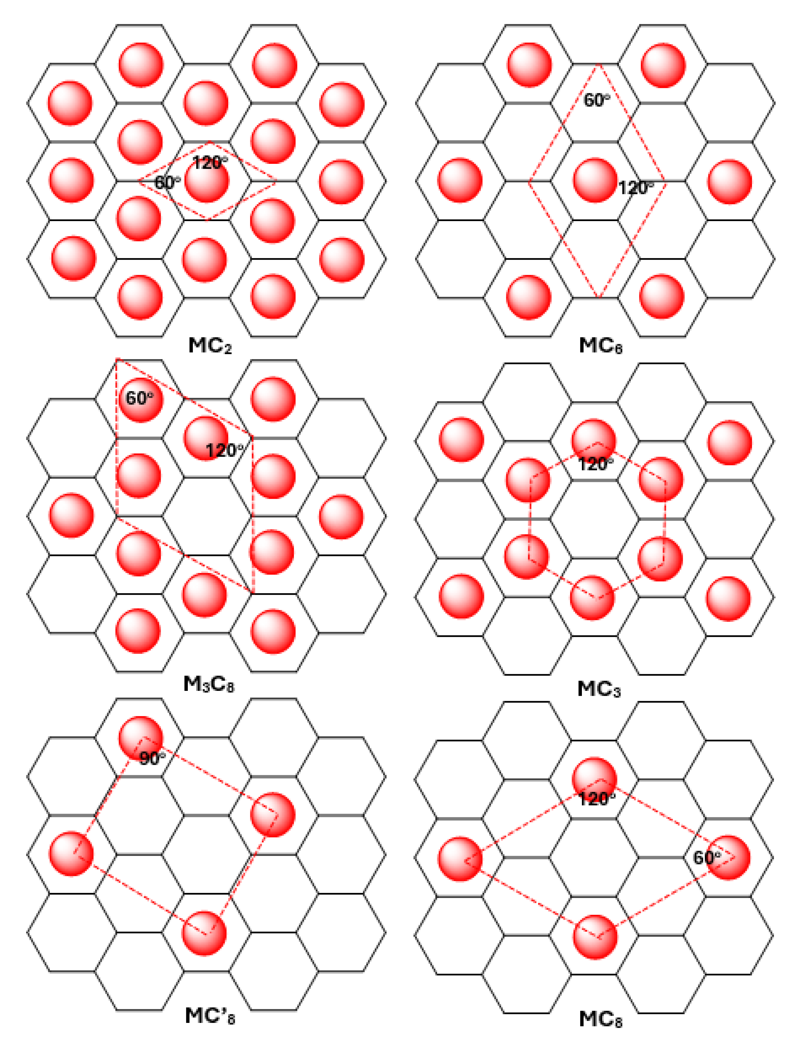
Figure 3.
Schematic showing lattice vectors and angles in the hexagonal unit cell.
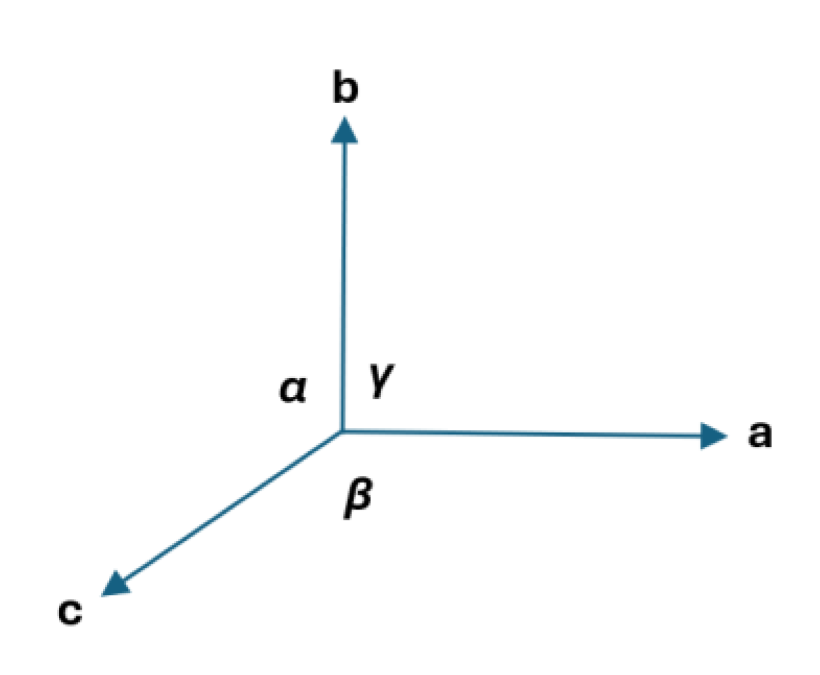
Figure 4.
Top and side view of the trigonometric and geometric derivation of height of unit cell (c) in GIC using the sphere-in-contact theorem. Lithium atom shown in red and carbon atoms shown in blue and orange. The carbon atom center is shown by a black dot.
Figure 4.
Top and side view of the trigonometric and geometric derivation of height of unit cell (c) in GIC using the sphere-in-contact theorem. Lithium atom shown in red and carbon atoms shown in blue and orange. The carbon atom center is shown by a black dot.
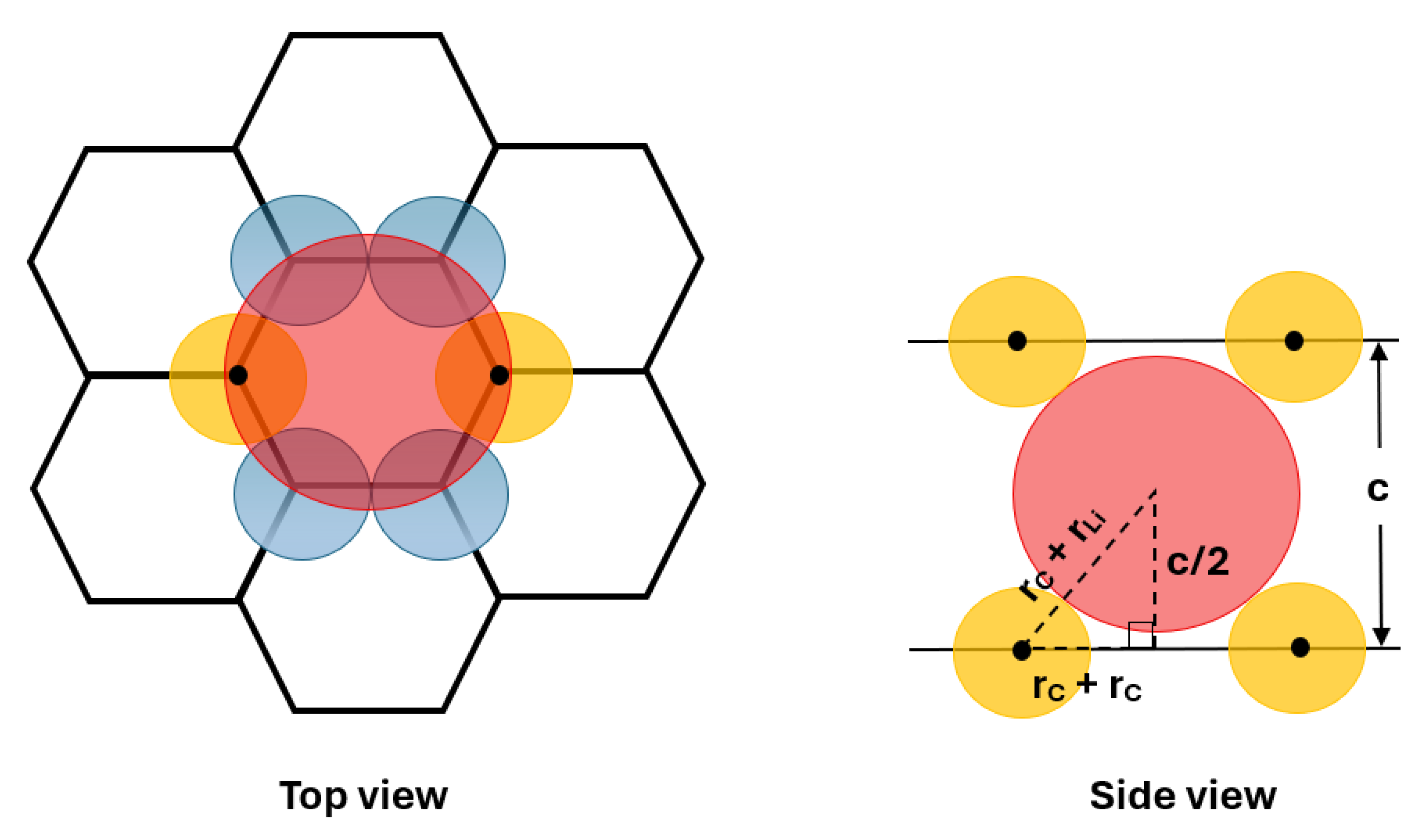
Figure 5.
Nearest neighbour interactions between intercalates (green) in various GICs. The graphene layer is shown by hexagonal wire-frame model.
Figure 5.
Nearest neighbour interactions between intercalates (green) in various GICs. The graphene layer is shown by hexagonal wire-frame model.
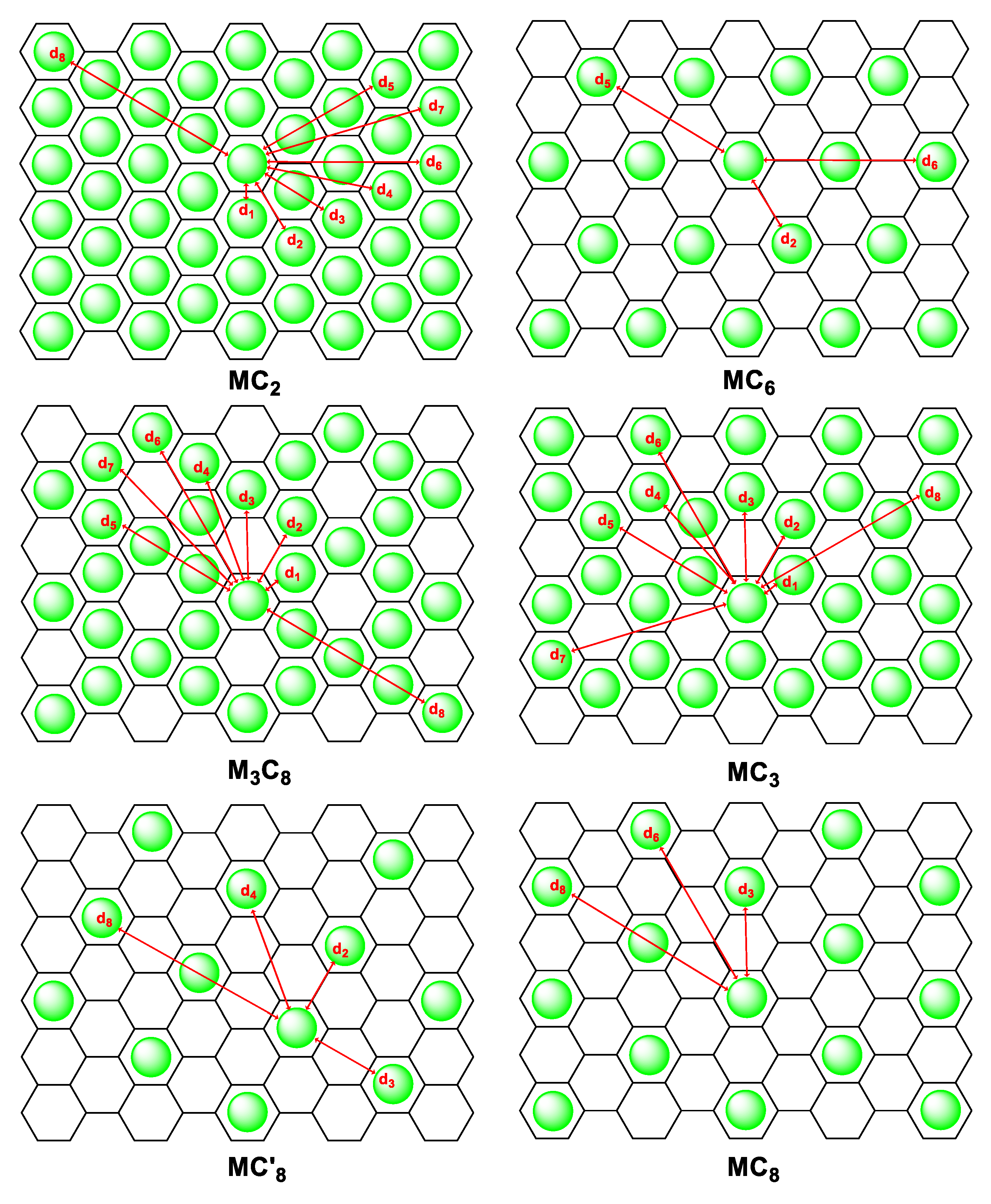

Table 1.
Unit cell volume of the various empirical formulas of GIC using the sphere-in-contact model.
Table 1.
Unit cell volume of the various empirical formulas of GIC using the sphere-in-contact model.
| Formula | Analytical equation of density |
VLi, GIC cm3 |
VNa, GIC cm3 |
VK, GIC cm3 |
VRb, GIC cm3 |
VCs, GIC cm3 |
| MC2 | 2.65 | 3.59 | 3.76 | 6.25 | 8.00 | |
| MC6 | 2.25 | 2.42 | 2.21 | 3.00 | 3.48 | |
| M3C8 | 2.50 | 3.15 | 3.18 | 5.03 | 6.31 | |
| MC3 | 2.45 | 3.00 | 2.98 | 4.63 | 5.74 | |
| MC’8 | 2.20 | 2.27 | 2.01 | 2.59 | 2.92 | |
| MC8 | 2.20 | 2.27 | 2.01 | 2.59 | 2.92 |
Table 2.
Empirical formula and densities using the sphere-in-contact model for various Group 1 (i.e. Li, Na, K, Rb, Cs) intercalated graphite intercalation compounds (GICs).
Table 2.
Empirical formula and densities using the sphere-in-contact model for various Group 1 (i.e. Li, Na, K, Rb, Cs) intercalated graphite intercalation compounds (GICs).
| Formula | Analytical equation of density |
ρLi, GIC g⋅cm-3 |
ρNa, GIC g⋅cm-3 |
ρK, GIC g⋅cm-3 |
ρRb, GIC g⋅cm-3 |
ρCs, GIC g⋅cm-3 |
| MC2 | 2.65 | 3.59 | 3.76 | 6.25 | 8.00 | |
| MC6 | 2.25 | 2.42 | 2.21 | 3.00 | 3.48 | |
| M3C8 | 2.50 | 3.15 | 3.18 | 5.03 | 6.31 | |
| MC3 | 2.45 | 3.00 | 2.98 | 4.63 | 5.74 | |
| MC’8 | 2.20 | 2.27 | 2.01 | 2.59 | 2.92 | |
| MC8 | 2.20 | 2.27 | 2.01 | 2.59 | 2.92 |
Table 3.
Packing fraction (
| Formula | Analytical equation of density | ηLi, GIC | ηNa, GIC | ηK, GIC | ηRb, GIC | ηCs, GIC |
| MC2 | 1.073 | 1.262 | 1.936 | 2.095 | 2.623 | |
| MC6 | 0.461 | 0.513 | 0.717 | 0.767 | 0.936 | |
| M3C8 | 0.843 | 0.981 | 1.479 | 2.130 | 1.991 | |
| MC3 | 0.383 | 0.444 | 0.663 | 0.716 | 0.890 | |
| MC’8 | 0.385 | 0.419 | 0.565 | 0.602 | 0.725 | |
| MC8 | 0.385 | 0.419 | 0.565 | 0.602 | 0.725 |
Table 4.
Repulsive interaction energy between intercalates in GICs using the pen and paper approach to count the pairwise interactions.
Table 4.
Repulsive interaction energy between intercalates in GICs using the pen and paper approach to count the pairwise interactions.
| Empirical formula | n1 | n2 | n3 | n4 | n5 | n6 | n7 | n8 | Unet, δ =+0.08e | Unet, δ =+0.16e |
| (kJ mol-1) | (kJ mol-1) | |||||||||
| LiC2 | 120 | 103 | 64 | 115 | 56 | 65 | 50 | 28 | 2432 | 9729 |
| LiC6 | 0 | 38 | 0 | 0 | 27 | 24 | 0 | 0 | 207 | 827 |
| Li3C8 | 56 | 47 | 66 | 80 | 32 | 45 | 33 | 22 | 1321 | 5284 |
| LiC3 | 38 | 65 | 31 | 44 | 44 | 34 | 15 | 41 | 985 | 3941 |
| LiC’8 | 0 | 8 | 8 | 13 | 0 | 0 | 0 | 12 | 74 | 297 |
| LiC8 | 0 | 0 | 30 | 0 | 0 | 21 | 0 | 17 | 111 | 443 |
Disclaimer/Publisher’s Note: The statements, opinions and data contained in all publications are solely those of the individual author(s) and contributor(s) and not of MDPI and/or the editor(s). MDPI and/or the editor(s) disclaim responsibility for any injury to people or property resulting from any ideas, methods, instructions or products referred to in the content. |
© 2026 by the authors. Licensee MDPI, Basel, Switzerland. This article is an open access article distributed under the terms and conditions of the Creative Commons Attribution (CC BY) license (http://creativecommons.org/licenses/by/4.0/).
Copyright: This open access article is published under a Creative Commons CC BY 4.0 license, which permit the free download, distribution, and reuse, provided that the author and preprint are cited in any reuse.