

Submitted:
26 February 2026
Posted:
27 February 2026
You are already at the latest version
Abstract
Overexposure, and severe noise in aerial images taken by monocular UAVs under complex lighting conditions (such as dusk and backlight) . A three-stage adaptive enhancement and restoration algorithm based on a "divide and conquer" strategy is proposed. The core innovation of this scheme lies in firstly, using a lightweight U-Net network to perform precise semantic segmentation of the illumination component of the input image, generating a mask that divides the image pixels into four regions: underexposed, normal, exposed , and overexposed. This mask serves as a navigation map for subsequent differential processing. For underexposed regions , the algorithm employs a Retinex -guided illumination decomposition method, decomposing them into reflectance and illumination maps, and then correcting them through reflectance recovery and illumination adjustment networks respectively to improve brightness and restore details. To address the noise introduced during the enhancement process, a two-stage trained Generative Adversarial Network (GAN) is specifically designed as an image enhancement module, effectively denoising and improving visual realism. For severely overexposed regions , they are treated as occlusions, and image restoration is performed using contextual information through another complex GAN framework to intelligently reconstruct lost textures. Experimental results show that the proposed algorithm performs excellently on both self-built datasets and multiple public datasets in terms of objective metrics (such as NIQE) and subjective visual quality, especially demonstrating significant advantages in noise suppression and overexposed area restoration. This provides higher-quality image input for subsequent tasks such as object detection and 3D reconstruction. Ablation experiments further validated the effectiveness of each module.
Keywords:
divide and conquer strategy
; image enhancement
; image restoration
1. Introduction
With the rapid development of UAV technology, monocular UAVs have been widely used in military reconnaissance, environmental monitoring, urban planning, emergency rescue and other fields due to their advantages such as low cost, high flexibility and easy operation [1]. However, images taken by UAVs in complex lighting environments (such as dusk, night, backlight or scenes with strong point light sources) often face problems such as uneven brightness, blurred details and local overexposure or underexposure. These quality problems seriously restrict the accuracy and reliability of subsequent computer vision tasks (such as target detection, 3D reconstruction and semantic segmentation). Therefore, efficient and accurate enhancement processing of monocular UAV aerial images transmitted to the ground station has become a crucial research topic [2].
Low-light image enhancement and 3D reconstruction of highly reflective objects are two important and challenging research directions in the field of computer vision, and significant progress has been made in both in recent years.
In the field of low-light image enhancement, research methods have evolved from traditional algorithms to deep learning-led approaches. Traditional methods such as histogram equalization [3] and Retinex -based algorithms [4] can improve the overall brightness of images, but they rely on artificially designed priors, have poor adaptability to complex scenes, and are prone to introducing noise or color distortion during the enhancement process. Deep learning, with its powerful feature representation capabilities, has significantly promoted the development of this field. Current research can be mainly divided into three paradigms: supervised, unsupervised, and zero-shot learning. Supervised methods such as Retinex -Net [5], KinD [6] and its improved versions KinD ++ [7], URetinex -Net [8], Diff- Retinex network [9], and Retinexformer network [10] follow the two-stage approach of decomposition and enhancement, decoupling the image into illumination and reflection components, and then processing them separately, achieving significant results on paired datasets [4]. However, the performance of such methods is highly dependent on large-scale, high-quality paired low-light /normal-light datasets. Unsupervised methods such as the Zero-DCE network [11], which enhances brightness through curve iteration, and EnlightenGAN [12], which uses a generative adversarial network to establish a mapping between unpaired images; and the SCI network [13], which introduces a weight-sharing self-calibration module. Among the above unsupervised learning methods, Generative Adversarial Networks (GANs) have problems such as difficult training process and unstable convergence of loss function [9]. Zero-shot learning methods use only a single low-light image in the network optimization process and have strong generalization ability. However, they have problems such as insufficient information contained in a single image and reliance on manually defined prior information [14]. Recently, the PairLIE method proposed by Fu et al. [15] has broken through this limitation. It collects content from the LOL [5] dataset, uses two low-light images with the same content for training, and shares the prior of its reflection component, thus achieving high-quality enhancement without relying on paired data. Nevertheless, most existing deep learning methods treat low-light images as a whole for processing. Their unified enhancement strategy is difficult to deal with the characteristic differences of different regions inside the image (such as dark areas and possible highlight areas) at the same time, which may lead to the coexistence of under-enhancement and over-enhancement.
In the field of 3D reconstruction of highly reflective objects, structured light measurement technology [17] has become mainstream due to its high precision and efficiency. However, when facing highly reflective surfaces, the intensity of reflected light is very likely to exceed the dynamic range of the camera sensor, resulting in saturated overexposed areas in the acquired images, which in turn leads to the loss of 3D point cloud data. To suppress the influence of highlights, researchers have proposed a variety of technical paths. The multiple exposure method [18] expands the dynamic range by fusing image sequences at different exposure times. Although it can recover some details, it requires the acquisition of a large number of images, has low efficiency, and the optimal exposure time is difficult to determine in advance. The polarization filter method [19] filters out specular reflection light by adjusting the polarization angle, but while weakening highlights, it also reduces the signal-to-noise ratio and useful signal strength of the overall image. The multi-camera method [20] uses images acquired synchronously from different perspectives to complement data, but the system is complex, difficult to calibrate, and expensive. Currently, the adaptive fringe projection method [21] shows great potential. It calculates the optimal projection intensity of saturated pixels by establishing a light transmission model and generates an adaptive coded pattern for measurement, which is highly flexible. However, these methods mostly focus on avoiding or compensating for highlight problems at the hardware level or during the data acquisition stage. For single images that have already been acquired and contain mixed degradation (such as the simultaneous presence of low light and highlight), there is a lack of effective post-processing methods.
A comprehensive analysis of the current research status in these two fields reveals a common challenge and contradiction: existing methods often optimize for a single degradation type (such as overall low light or localized high reflectivity). However, in real-world scenarios, especially under complex imaging conditions (such as indoor backlighting, near windows, or objects with glossy surfaces), low light and overexposed highlights often coexist in different areas of the same image. Current mainstream methods, whether for low- light enhancement or highlight suppression, mostly employ global or uniform processing strategies, failing to fully consider the significant differences in brightness distribution and degradation characteristics across different regions of the image. This leads to a processing paradox: enhancing low-light areas may exacerbate overexposure in highlight areas; while suppressing highlights may result in further loss of detail in dark areas. Therefore, a computational imaging method capable of finely distinguishing and collaboratively processing low-light and highlight areas in an image is urgently needed.
2. Algorithm for UAV Aerial Photography of Complex Lighting Images Based on Divide-and-Conquer Strategy
Traditional global enhancement methods (such as histogram equalization) struggle to handle complex local lighting variations in aerial images, often leading to over- or under-enhancement. These methods apply a uniform transformation to the entire image, failing to balance enhancing shadow details with preserving highlight information. In drone aerial photography scenarios with extremely high dynamic range, this often results in amplified noise in dark areas or overexposure and loss of detail in bright areas.
In recent years, adaptive enhancement technology based on region segmentation has shown great potential due to its fine processing capabilities. The core idea of this type of method is "divide and conquer", that is, based on the prior information such as the brightness and reflectance of the image, the image is divided into different regions, and the most suitable enhancement strategy is applied to the characteristics of each region. This idea coincides with the core idea of Retinex theory, which understands the image as the product of the illumination component and the reflection component [4]. Based on this, we can accurately segment the image region by estimating the illumination component: underexposed regions correspond to extremely low illumination values, details are buried in darkness and noise is significant; overexposed regions correspond to saturated illumination values, pixel information is lost; and normally exposed regions have moderate illumination intensity.
In view of the unique perspective of monocular UAV images, their susceptibility to point light sources, and the need to balance processing efficiency, this paper aims to propose a comprehensive solution that combines brightness region segmentation, illumination correction guided by Retinex theory, and specular restoration based on deep learning.
The structure diagram of this article is as follows:
The adaptive enhancement scheme based on region segmentation proposed in this paper is clearly presented in Figure 1, and its overall process and core idea are shown. As shown in the figure, the scheme fully embodies the "divide and conquer" three-stage architecture.
First, the input image is processed by the U-Net Region Segmentation module [22], which estimates the illumination components to achieve preliminary region segmentation based on luminance prior. Then, a lightweight network is used for precise segmentation, and its output is clearly labeled as four channels in the Four-channel mask: underexposed region ( Channel 0 ), normal region ( Channel 1 ), and exposed and overexposed regions ( Channels 2 & 3 ).
Subsequently, the process enters the partition adaptive enhancement phase. For underexposed areas ( Channel 0 ), they are fed into the Low-light repair module. This module not only performs adaptive brightness enhancement guided by the illumination attention map, but more importantly, it introduces blind image super- resolution and denoising technology based on generative adversarial networks. This effectively suppresses noise and blur while enhancing details in dark areas, avoiding the noise amplification problem caused by traditional global methods.
For overexposed areas ( Channels 2 & 3 ), the system redirects to the Exposure and overexposure repair module. This module employs image restoration techniques, utilizing contextual information from surrounding unsaturated areas to intelligently reconstruct textures lost due to highlight clipping, thus supplementing information in the oversaturated areas.
Finally, all the image streams that have undergone partitioning are converged to the Image enhancement module for global optimization and fusion, ultimately outputting a visually balanced, detail-rich, high-quality image that provides reliable input for subsequent advanced vision tasks.
2.1. Mask-Based Dual- Module Underexposed Area Repair
Based on the semantic mask generated by the illumination component segmentation module, the system will adopt differentiated restoration strategies for different regions. Specifically, for pixels marked as underexposed areas (Channels 0) in the mask, this scheme initiates a dedicated restoration process based on illumination decomposition. The core idea is that the information in underexposed areas is not completely lost, but only severely darkened, so they can be physically decoupled from normally exposed areas (illumination and reflection) and processed separately.
The restoration process begins with the low-light restoration module. This module decomposes the image data of the underexposed areas into a reflectance map (representing the scene's inherent color and texture) and a illumination map (representing the intensity of projected light). These two components are then fed into two dedicated sub-networks for processing: a reflectance restoration network denoises, deblurs, and corrects the color of the reflectance map to restore sharp details; and an illumination adjustment network enhances and homogenizes the illumination map to improve overall brightness. The outputs of these two networks are then recombined and synthesized to initially obtain the image with improved brightness.
However, noise is often introduced or amplified during the process of brightness enhancement and detail restoration. To obtain better visual results, the initially restored image is fed into an image enhancement module. This module uses a two-stage trained generative adversarial network. In the first stage, it learns the basic mapping through pixel loss to stabilize the network. In the second stage, it combines pixel loss, perceptual loss, and adversarial loss to perform deep denoising and detail enhancement on the image, ultimately outputting a restored image with high brightness, low noise, and rich detail.
The entire underexposure restoration process is guided by semantic masks: all network operations, such as decomposition, adjustment, and enhancement, focus primarily on the underexposure area defined by the mask for effective supervision and loss calculation, while the normally exposed area is protected from unnecessary modification during the restoration process. This mask-guided approach ensures the targeted, localized nature of the restoration and the overall naturalness of the image.
2.1.1. Low-Light Restoration Module
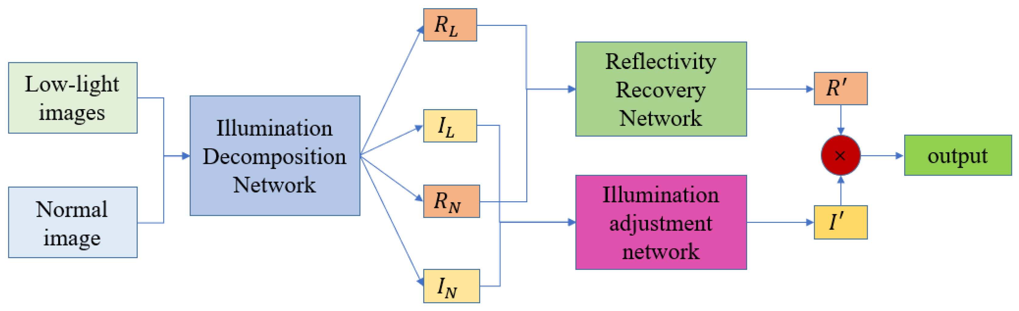
Figure 2, the module starts with low-light and normal images. These are first fed into the blue Illumination Decomposition Network, which decouples the reflection components ( , ) and illumination components ( , ) respectively. This process is crucial for the decomposition network's loss function; it supervises the network to accurately decouple image information into two independent components, laying the foundation for subsequent processing.
Next, the components obtained from the decomposition are divided into two groups:
- Reflection component recovery: The system enters the Reflectivity Recovery Network to learn and recover clearer, less noisy reflection components .
- Illumination component adjustment: The light components are fed into the illumination adjustment network to generate the adjusted illumination components I'.
Finally, the optimized reflection component is multiplied by the illumination component I'to obtain the final output image.
Figure 2.
Low -light restoration structure diagram.
This reconstruction step, under the joint constraints of the loss function, ensures that the output improves shadow brightness and detail while maintaining natural lighting transitions and realistic color textures. Therefore, in the low-light restoration module, the design of the loss function is crucial to ensuring effective decomposition. The loss mainly consists of decomposition network loss, illumination smoothing loss, and illumination constraint loss. The decomposition network loss applies to both the reflection and illumination components to ensure their accuracy during the decomposition process. The illumination smoothing loss aims to maintain the continuity of the illumination map and prevent unnatural local abrupt changes; its expression is:
in , is the gradient operator in the horizontal and vertical directions. This loss penalizes the gradient magnitude of the lighting map, thus making its changes smoother. The lighting constraint loss is used to ensure that the estimated value of the lighting map is within a reasonable physical range (usually [0,1]), and is defined as follows:
The L1 norm form of the loss penalizes illumination values outside the [0,1] interval, thus constraining the illumination intensity within an effective range. Furthermore, the low-light restoration module employs two complementary illumination-guided losses to further improve the decomposition quality. The illumination smoothing mutual loss ( ) utilizes the gradient information between the underexposed image ( ) and the corresponding normally exposed image ( ), and adaptively reduces the smoothing constraint in regions of rapid gradient change and strengthens smoothing in gentler regions through an exponential weighting function. Its formula is:
Mutual loss of light input:
The illumination input mutual loss ( ) uses the grayscale version ( ) of the input image as a structural reference to guide the gradient direction of the illumination map (I) to align with the structural edges of the input image. Its expression is:
This loss function normalizes the illumination gradient to the gradient of the input image, ensuring that the structural changes in the illumination map remain consistent with the structure of the original image, thus avoiding the introduction of unreasonable textures into the illumination map. In summary, the aforementioned loss functions work together to constrain the decomposition network, enabling it to robustly separate high-quality, physically meaningful reflectivity and illumination components from underexposed images. This provides a less noisy and more detailed intermediate representation for subsequent image enhancement modules.
After completing the decomposition of illumination and reflectivity, the reflectivity recovery network and the illumination adjustment network will perform special correction processing on the two components respectively. Their optimization process is driven by their respective loss functions and supplemented by specific gradient calculation methods.
- Illumination adjustment network loss
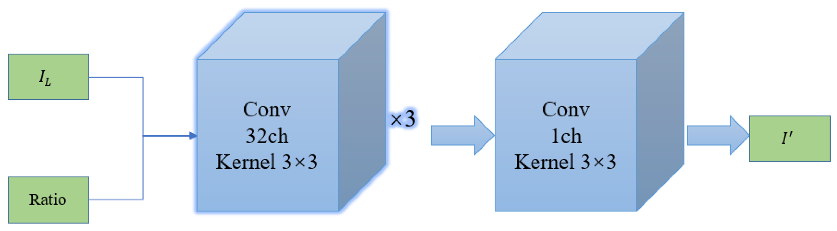
As shown in the figure, the core processing flow of the network begins with two key inputs: the illumination component of the underexposed image.
Ratio signal, representing its relationship with the target illumination. They are sequentially passed through two core convolutional modules:
- Deep Feature Extraction: First, a 32-channel, 3x3 kernel convolutional block is used, with the "×3" explicitly indicating that this operation is repeated 3 times. This constitutes the deep feature extraction part of the network, capable of extracting features from the input.... In Ratio, we learn and encode complex brightness mappings and spatial context relationships.
- Channel fusion and output: Next, a convolution operation with a 1-channel, 3x3 kernel is used to fuse the deep features extracted earlier and map them back to a single channel, ultimately outputting the adjusted ideal illumination distribution .
Light restoration structure diagram
Figure 3.
Illumination recovery structure diagram.
The illumination adjustment network is responsible for processing the decomposed illumination map , aiming to adjust it to an ideal illumination distribution with reasonable brightness and spatial smoothness . Here , is the one the network expects to generate . The training of this network is driven by a total loss, which combines pixel-level accuracy constraints with edge structure preservation constraints, specifically defined as:
Where is the mean squared error loss, which aims to minimize the pixel value difference between the output lighting map and the target lighting map:
This is gradient loss, which penalizes the difference in gradient between the output and the target in the horizontal and vertical directions. This ensures that the adjusted lighting map maintains consistency with the target in terms of edge and texture structure, thus avoiding the introduction of unrealistic lighting abrupt changes or structural distortions during brightness enhancement. Gradient loss is defined as:
- 2.
- Reflection recovery of network loss
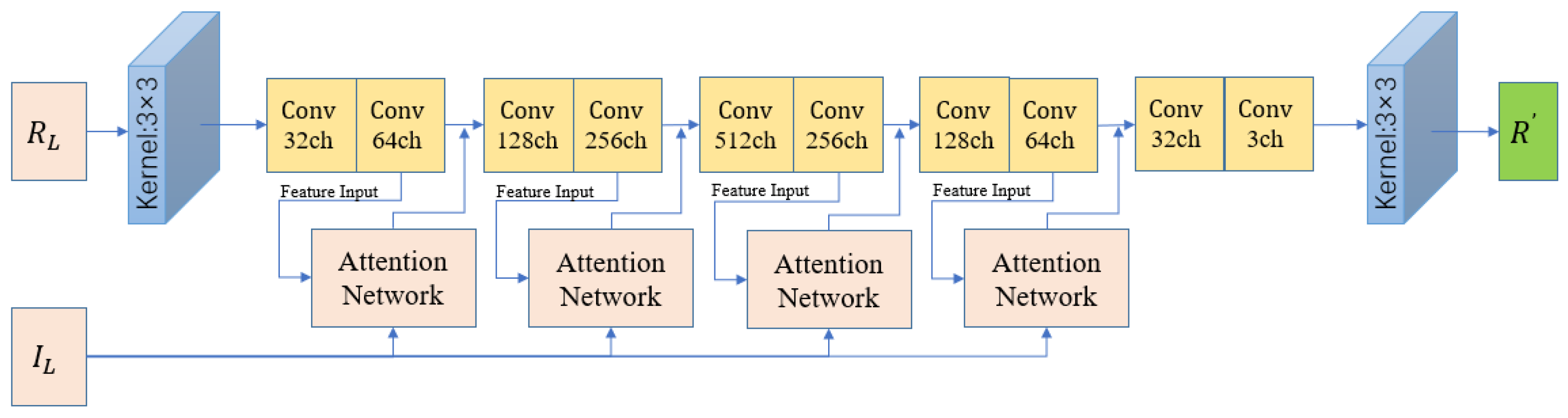
First, looking at the overall process (Figure 4), the network accepts two key inputs:
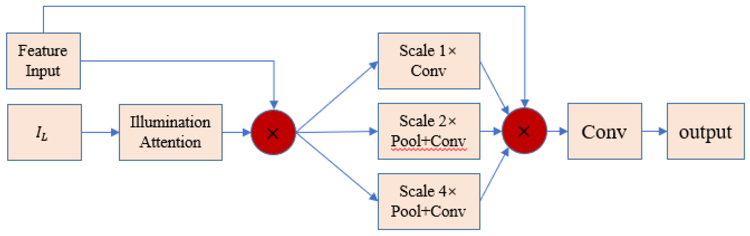
The main feature input consists of the deep features of the low-light reflectance component that need to be processed , along with the illumination attention guidance. Its structure is shown in Figure 5. The core function of this module is to generate an illumination attention map to identify the brightness, noise, and distortion levels in different regions of the image, thereby guiding the main network to perform adaptive and targeted inpainting.
Figure 4.
Reflection recovery network structure diagram.
The attention network structure is as follows:
Figure 5.
Attention network structure diagram.
The reflectance restoration network focuses on processing the decomposed reflectance map R. Since low-light images are often accompanied by significant noise, blur, and color distortion, the core task of this network is to denoise, deblur, and color correct the reflectance map to recover the inherent reflective properties of the scene in a clear, clean, and color-accurate manner. Its training objective is guided by a total loss that integrates pixel accuracy and perceptual quality.
Here, is the mean squared error loss, which aims to approximate the target reflectivity from the pixel value:
Considering the high sensitivity of human vision to structural information, this scheme introduces structural similarity loss to improve the quality of the reconstructed image at the perceptual level, making it closer to the target image in terms of brightness, contrast, and structure. The loss is defined as follows:
The formula for calculating SSIM (Structural Similarity Index) is as follows:
Here, and represent the mean of the image patch and, respectively , and are its variances, and and are its covariances. The constant is used for stability calculations and is usually taken as , where is the dynamic range of the pixel value (usually 1).
- 3.
- Gradient calculation
In the calculation of the above loss functions (such as the gradient-related loss in the low-light restoration module), the image gradient is efficiently obtained through discrete difference convolution kernels. Specifically, the horizontal gradient and the vertical gradient are approximated using the following 2×2 convolution kernels:
To ensure the comparability of gradient values across different images and regions and to enhance training stability, the calculated gradients are typically normalized. The normalization formula is as follows, where ϵ is a very small constant used to prevent division by zero:
By designing targeted composite loss functions for the illumination adjustment network and reflectivity recovery network, and supplementing them with a stable and efficient gradient calculation process, underexposed images can be systematically enhanced. While improving overall brightness, noise is effectively suppressed, details are restored, and colors are corrected, ultimately resulting in high-quality images with natural visual effects and rich details.
2.1.2. Image Enhancement Module
To address potential issues such as increased noise and blurred details that may persist after decomposition and correction, the final crucial step in the underexposure restoration process is the image enhancement module. This module aims to further suppress noise, enhance texture details, and improve the overall visual realism of the image. To achieve stable and efficient enhancement, this approach employs a two-stage training strategy: the first stage involves pre-training a stable network, and the second stage is adversarial refinement enhancement.
Phase 1: Pre-training a stable network
A pixel-level, stable input-output mapping for the generator network. This stage avoids complex adversarial training, using only pixel-level L1 loss to guide the generator in learning the fundamental transformation from the noisy input image xi to the relatively clean target image yi. This effectively avoids the instability of early adversarial training, providing a good initial model for the refined training in the second stage. The loss function for this stage is defined as:
Where is the image output by the generator, is the target image, and is the total number of pixels.
Phase Two: Competitive Refinement Enhancement
After obtaining a stable generator, the second stage introduces a Generative Adversarial Network ( GAN) framework to pursue higher perceptual quality and more realistic texture details. The goal of this stage is to make the generated images visually indistinguishable from high-quality real images. To this end, the generator's loss function integrates pixel loss, perceptual loss, and adversarial loss to form a composite optimization objective. The discriminator 's goal is to accurately distinguish between generated and real images.
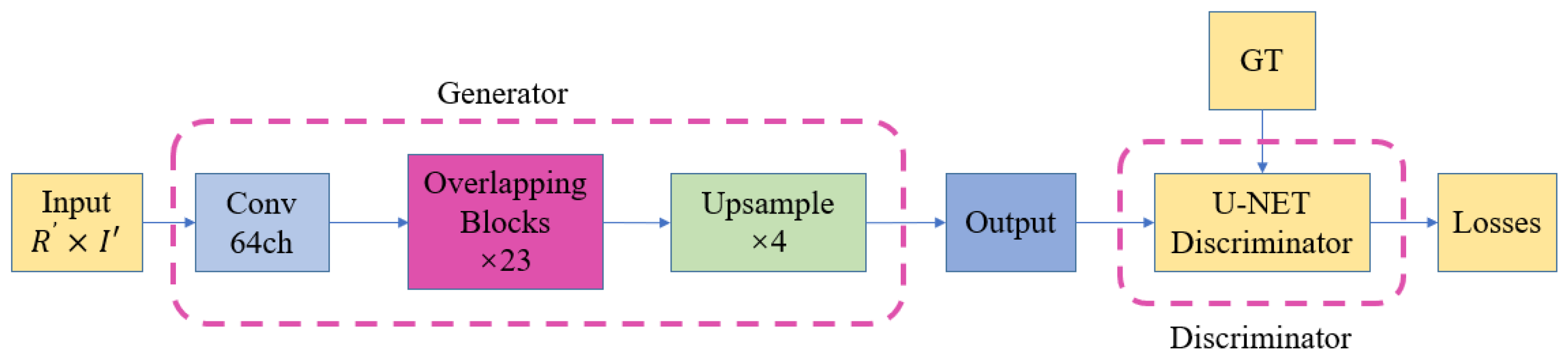
First, Figure 6 (Network Structure Diagram of Image Augmentation Module) confirms the Generative Adversarial Network (GAN) framework you mentioned. The diagram clearly shows that the entire module consists of two parts: a generator and a discriminator.
The generator takes the image processed by the preceding module as input and its task is to "generate" an enhanced image. Its output, along with the real high-quality image (GT), is fed into the discriminator.
Discriminator: The U-Net structure can perform pixel-level real and fake discrimination, thus providing the generator with more refined gradient feedback with more spatial location information.
Image enhancement module network structure:
Figure 6.
Network structure diagram of image enhancement module.
the Overlapping Blocks in the generator is as follows:
Figure 7.
Overlapping Blocks Structure Diagram.

The structure diagram of the block is as follows:
Figure 8.
Block Structure Diagram.

- 1.
- Generator loss
The generator's total loss LG is a weighted sum of three losses, designed to simultaneously guarantee pixel accuracy, high-level feature similarity, and visual realism:
Wherein, the weights are set to
- Pixel loss ( L1 loss): To ensure the enhanced image is structurally faithful to the target, L1 loss is continued in this stage. However, to incentivize the generator to recover sharper edges, the target image is a Ground Truth image preprocessed with an unsharpened mask ( USM). The loss is defined as:
- Perceptual Loss ( VGG Loss): To approximate realistic images at the semantic and textural levels, this approach employs a perceptual loss based on a pre-trained VGG19 network. This loss compares the feature maps of the generated image and the unsharpened target image at specific intermediate layers of the VGG network, thereby guiding the generator to learn image features that better match human perception. The loss is defined as the L1 norm-weighted sum of the feature maps:
Here, represents the feature extraction function of the l-th layer of the VGG19 network, is its dimension, i.e., the number of channels, height, and width of the l -th layer feature map, and represents the weights of the l-th layer. The feature layers used and their weight configurations are as follows: conv1_2(0.1), conv2_2(0.1), conv3_4(1.0), conv4_4(1.0), conv5_4(1.0). Higher weights are assigned to deeper features to capture higher-level semantic and texture information.
- Generator Adversarial Loss: To make the generated image approximate the real image in terms of distribution, an adversarial loss based on binary cross-entropy (BCE) is introduced. The goal of the generator is to "deceive" the discriminator into classifying the generated image as "real". The loss is defined as:
- 2.
- Discriminator loss
The discriminator structure diagram is as follows:
Figure 9.
Discriminator Network Structure Diagram.
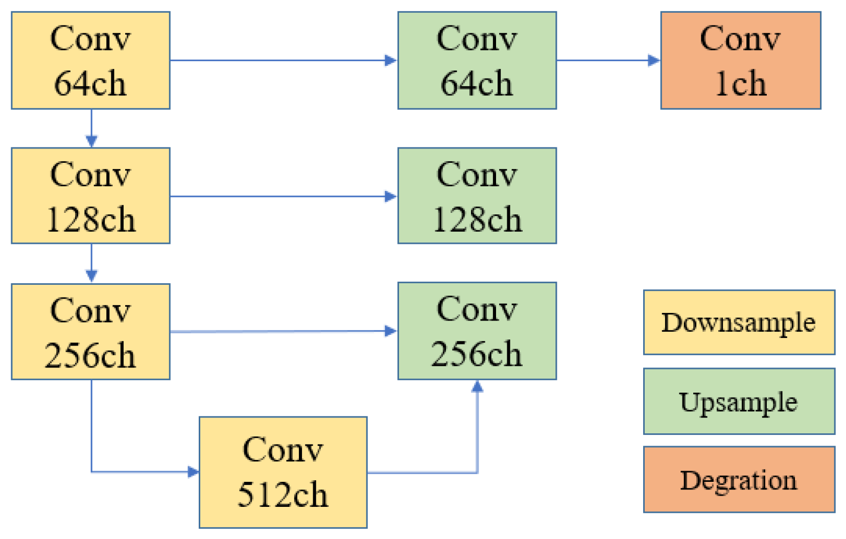
The degradation mode is:
Figure 10 clearly illustrates a controllable and repeatable image degradation network structure. Starting with a real high-resolution image ( GT), a series of modules simulating degradation factors in real mobile phone shooting (such as blur, resize, add noise, and compress) are introduced to finally synthesize a low-resolution, flawed image (LR).
For the discriminator, its goal is to accurately distinguish between real and generated images . Its total loss consists of two parts:
The loss for determining whether a real image is real is:
The loss for determining whether a generated image is fake is:
The image enhancement module employs a two-stage training strategy, transitioning from stable learning of the basic mapping to refined enhancement of perceptual quality. In the core adversarial training phase, the generator jointly optimizes pixel loss ( L1), perceptual loss (VGG), and adversarial loss (GAN), effectively denoising, sharpening details, and generating visually more natural and realistic textures while maintaining structural accuracy. The discriminator, by continuously optimizing its discrimination capabilities, in turn drives the generator to produce higher-quality images. Ultimately, this module works in conjunction with the aforementioned decomposition, adjustment, and restoration modules to achieve comprehensive, high-quality restoration of underexposed images, improving brightness, contrast, detail, and realism.
2.2. Repairing Exposed and Overexposed Areas
Within the overall "divide and conquer" restoration framework, the processing strategies for normally exposed and overexposed areas differ fundamentally from those for underexposed areas. This differentiation stems from the precise semantic analysis of the image performed in the initial stage by the illumination component segmentation module. This module, centered on a lightweight U-Net network, takes the brightness component of the image as input and learns the illumination semantics of each pixel through an encoder-decoder architecture, ultimately outputting a four-channel probability map corresponding to four predefined categories: underexposed, normally exposed, exposed (highlights), and overexposed. After argmax operation, we obtain a semantic segmentation mask, which serves as a "navigation map" for the entire restoration process, precisely guiding subsequent differentiated processing of different areas.
Overexposed areas marked in the mask, pixel information is largely lost or destroyed due to highlight clipping, making it impossible to recover them by adjusting lighting as with underexposed areas. Therefore, this solution abandons simple lighting adjustments and instead employs a context-based image inpainting method. The core idea is to treat overexposed areas as "information-missing" parts of the image and utilize the contextual semantic information provided by the surrounding undamaged normal areas to infer and reconstruct visually reasonable and coherent pixels. To achieve high-quality reconstruction, we use a Generative Adversarial Network ( GAN) framework, combined with various carefully designed perceptual and adversarial losses, to ensure that the generated textures are not only pixel-accurate but also achieve natural and detailed restoration effects in terms of semantic coherence, visual realism, and integration with the surrounding environment. This strategy ensures intelligent and reliable content supplementation for areas with severely lost information.
The overall structure diagram is shown in Figure 11:
2.2.1. Overview of Loss Function and Weight Configuration
The training of the entire repair network is driven by a combined generator total loss and a discriminator total loss , and its structure is as follows:
The weights of each loss term are optimized to achieve a balance between different constraints. The specific weight values are as follows: Reconstruction Loss (Known Region) , Reconstruction Loss (Missing Region) , VGG Perceptual Loss Weight , ResNet Perceptual Loss Weight , Generator Adversarial Loss Weight , and Feature Matching Loss Weight . As can be seen from the weights, this scheme particularly emphasizes ResNet Perceptual Loss and Feature Matching Loss to prioritize ensuring the consistency between the repaired content and the real image in high-level semantics and the discriminator feature space.
2.2.2. Detailed Explanation of Generator Loss
Figure 12, the encoder structure diagram, illustrates the first stage of information compression and feature extraction. The input ( +Mask ) sequentially passes through three FFC Downsample modules, gradually increasing the number of channels from 64ch to 256ch, while simultaneously reducing the spatial size. Figure 13, the FFC ResNet Blocks structure diagram, is the inference center of the generator. The features output by the encoder enter a deep network composed of 18 such blocks. The core of each block is two FFC (Fast Fourier Convolution) operations, combined with BN+ReLU for normalization and activation. The key to FFC is its ability to process features in both the spatial and frequency domains simultaneously, thereby efficiently integrating the local details and global structural information of the image. Figure 14, the decoder structure diagram, is responsible for rendering the inference results. It receives the features after deep inference and gradually upsamples them through three Upsample modules, gradually reducing the number of channels from 256ch to 64ch, restoring the spatial size to the original image size.
The generator design follows a classic encoder -decoder paradigm, and the generator loss incorporates multiple supervisory signals:
-
Weighted Reconstruction Loss ( ): This is the most basic pixel-level constraint. This scheme innovatively introduces a distance-weighted mechanism, distinguishing between known regions ( ) and missing regions ( ) through masking ( , ) , and assigning them different weights ( , ). This means that the loss only imposes strict reconstruction constraints on known (non-overexposed) regions, ensuring that existing intact information is not modified; while for missing regions that need to generate content, no hard pixel-level constraints are imposed, giving the generative network greater creative freedom. Its formula is:The pixel weights are:
- Perceptual Loss: This scheme primarily employs a perceptual loss based on the ResNet50-dilated network to constrain the generated content at a higher level of semantic features. It calculates the L2 distance between the generated image and the real image across multiple intermediate feature maps of ResNet, guiding the semantics of the repaired region to remain consistent with the global context. Its definition is:
Here, represents the feature extraction function of the l-th layer of ResNet50-dilated. The weights are set very high here to highlight the importance of semantic consistency.
-
Generator Adversarial Loss( ): Employs an adversarial loss based on the softplus function, aiming to "fool" the discriminator into believing the generated image is real. The loss is defined as:in The softplus function is defined as: This loss encourages the generator to produce visually realistic textures that are difficult to distinguish from real images.
- Feature matching loss ( ): To stabilize GAN training and improve generation quality, a feature matching loss is introduced. It constrains the generated image and the real image to be as close as possible to the intermediate multi-layer feature representations of the discriminator D. Similarly, this loss is only calculated on known regions (corresponding through downsampling masks ), avoiding imposing unreasonable intermediate layer feature constraints on the generated content of unknown regions. Its formula is:
Here, represents the intermediate features of the discriminator's l -th layer. This loss is given a very high weight ( ), which is crucial for ensuring that the generated image and the real image are distributed consistently in the discriminator's feature space.
2.2.3. Detailed Explanation of Discriminator Loss
A four-layer convolutional discriminator outputs partial probabilities of being true or false, thus determining the quality of the generated data. The intermediate layer features are used for feature matching loss. Multiple layers of features are extracted and compared to improve stability. The discriminator structure is shown in Figure 15.
The discriminator aims to accurately distinguish between real images and restored generated images . Its total loss also uses the softplus function and includes an R1 gradient penalty to stabilize training.
in:
- True Sample Loss: Determines a true image as real.
- Fake Sample Loss: This is a key design feature. For the generated image, the discriminator is only encouraged to classify as fake in known regions (corresponding to 1 − m ), while no strong constraint of "classifying as fake" is imposed on missing regions (corresponding to m). This allows the discriminator to focus on evaluating the consistency of known regions, which helps the generator better utilize the context. The loss is:
- R1 gradient penalty: Apply gradient penalty to the real data to enhance the Lipschitz continuity of the discriminator and prevent training collapse .
For the restoration of exposed and overexposed areas, this solution employs a context-complete adversarial generative approach. By introducing a mask-weighted mechanism, strict pixel-level constraints are imposed only on known regions in the reconstruction loss, while constraints are released for missing overexposed areas. The core driving force of training comes from the high-level ResNet perceptual loss, the discriminator- driven adversarial loss, and the feature matching loss that ensures consistent feature distribution. The discriminator is also designed in conjunction with masks to more reasonably evaluate image quality. This multi-loss collaborative, mask-guided GAN framework enables the network to effectively utilize intact information around overexposed areas, intelligently inferring and generating semantically reasonable, textured, and seamlessly integrated restoration content.
3. Result
The algorithm in this paper divides the image into partitions using a U -NET network, and then applies different processing methods to different regions. For underexposed areas, low- light recovery and image enhancement are used, while for overexposed areas, image inpainting is used. This solves the problem that enhancing low-light areas may aggravate overexposure in highlight areas, while suppressing highlights may lead to further loss of details in dark areas.
Each module was trained separately, mainly in three stages. For the first stage, the underexposure part, 480 pairs of low-light/normal images were selected from the LOL Dataset dataset, using TensorFlow version 2.10.0. For the second stage, the image enhancement part, over 3,000 images from the DF2K dataset were used, using PyTorch version 2.1.2. For the third stage, the exposure and overexposure part, in addition to selecting 8,000 scene images from the Places365-Standard dataset, 7,000 normally exposed, overexposed, or normally exposed images from the UAV dataset were also added, using PyTorch version 2.1.2. Our experimental hardware platform consisted of an AMD EPYC 7K62 48-Core Processor, two NVIDIA RTX 4090 graphics cards, 48GB of RAM, and a Windows 11 operating system.
Currently, the mainstream methods for image processing are mainly low-light processing, which enhances the underexposed parts of the image. For exposed and overexposed parts, the mainstream methods are only HDR and ExposureCorrection. However, these two methods are only useful for some exposure situations, but cannot handle overexposed parts. Therefore, the following test experiment will be divided into two parts: underexposed and overexposed.
3.1. Underexposure Experiment
3.1.1. Dataset Testing
Compared it with six state-of-the-art deep learning-based methods on our self-built test set, including DRBN, Zero-DCE, KinD ++, Zero-DCE++, URetinex - Net, and PairLIEE. To verify the algorithm's generalization ability, we selected images from various real-world environments for visualization comparison, randomly selecting images from our self-built dataset and public datasets at a ratio of 3:7 for testing. Several mainstream no-reference evaluation metrics were used for quantitative comparison, including LOE, BRISQUE, NIQE, Brightness, Contrast, Entropy, and Colorfulness. LOE reflects the naturalness of the enhanced image; a lower value indicates a closer proximity in brightness order between the enhanced and original images, resulting in higher naturalness. BRISQUE reflects image quality through feature analysis; a lower value indicates a more realistic image. NIQE evaluates the quality of no-reference images; a smaller value indicates better perceived quality. Brightness represents the average brightness of the image, Contrast represents the image contrast ratio, Entropy represents the image entropy, reflecting the amount of information, and Colorfulness represents the richness of the image colors. From Table 1, our algorithm performs well in all metrics.
3.1.2. Public Datasets
To further verify the generalization performance of the algorithm, we tested it on five public datasets, including DICM, LIME, LOL, MEF, and NPE. Because these datasets contain different reference images, we chose NIQE as the evaluation metric. Table 2 shows that our algorithm performs well on the LIME and NPE datasets.
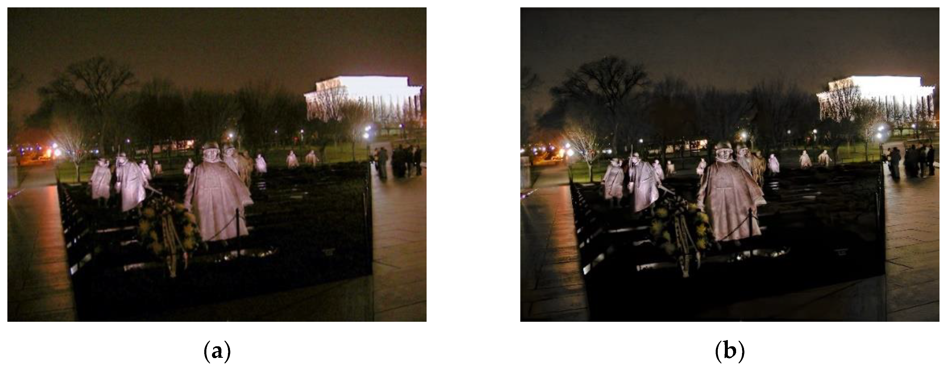
Figure 16 shows a comparison of the results, including images from three scenarios: indoor close-up, outdoor scenery, and drone aerial photography. We can see that, aside from our algorithm, images with low brightness still exhibit significant noise after processing, which is detrimental to subsequent steps such as 3D reconstruction. We will compare the images using UREtinex - Net, which also performs well in objective evaluation metrics.
shown in Figure 17, which compares noise levels, the left image is processed by UREtinex -Net, while the right image is processed by our algorithm. It's clear that the sky in the left image contains dense noise with a yellowish tint, while the sky in the right image has significantly less noise, and the overall image is much clearer. The presence of this noise will affect subsequent steps such as 3D reconstruction.
Figure 17.
Noise Comparison Chart.
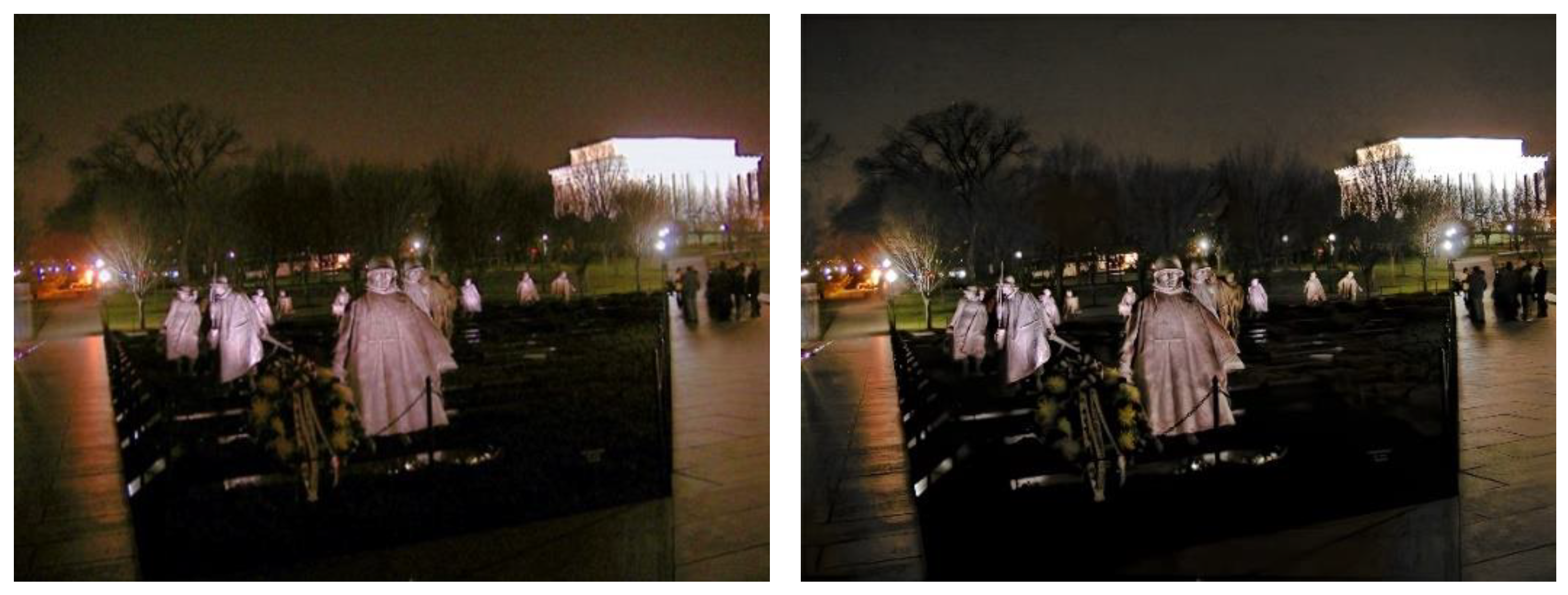
Figure 18.
Noise Comparison Chart.
3.2. Exposure and Overexposure Experiment
For handling exposure and overexposure, we generally use polarizing filters at the physical level, but polarizing filters primarily address reflection issues. At the algorithm level, traditional exposure handling algorithms include HDR, while the more advanced algorithm is ExposureCorrection. However, both algorithms can only handle some simple exposure problems and cannot solve complex exposure or overexposure issues.
3.3. Ablation Experiment
This paper presents three sets of ablation experiments to verify the effectiveness of each module: the underexposure processing module, the image enhancement module, and the exposure and overexposure repair module.
Figure 20 shows the comparison results of the underexposure processing module. Without the underexposure processing module, the entire image is quite dark. Figure 21 shows the comparison results of the image enhancement module. Without the image enhancement module, the middle image has more noise in the sky, which will affect subsequent processing, such as 3D reconstruction. Figure 22 shows the comparison of the exposure and overexposure modules. After processing with the exposure and overexposure modules, the store sign in the image is clearer, and the second detail image shows more details of the store.
4. Discussion
The three-stage adaptive enhancement and repair algorithm proposed in this article based on the "divide and conquer" strategy has achieved the expected results in dealing with the common complex illumination coexistence (such as underexposure and overexposure) common in monocular drone aerial images. Experimental results show that this algorithm is competitive in both subjective visual quality and multiple objective indicators (such as NIQE, LOE). This first verifies the rationality and necessity of the "divide and conquer" idea. Different from existing methods that uniformly enhance the image as a whole (such as KinD++, URetinex-Net) or only target a single degradation type (such as low-light enhancement), this study treats the image as a collection of regions with different illumination attributes. Through illumination component segmentation and navigation, optimization enhancement and generative repair strategies are used for underexposed and overexposed areas respectively. This differentiated processing fundamentally solves the processing paradox of "enhancing the dark parts will make the overexposure worse, suppressing the highlights will make the dark parts darker", and provides a new technical path for image enhancement in complex lighting scenes.
Another contribution of this research work is that it not only focuses on the improvement of brightness, but also emphasizes the quality of the enhanced image. In the underexposure repair process, we specially integrated a two-stage trained GAN image enhancement module, which largely suppresses the common noise amplification and detail blurring problems of traditional low-light enhancement methods, as shown in Figure 16 and Figure 17. This makes the enhanced image more suitable for downstream tasks that require stringent input quality, such as target detection and 3D reconstruction. For overexposed areas where information is severely lost, this study did not follow simple highlight suppression or HDR ideas, but turned to a context-based image restoration paradigm. Through the mask-guided generative adversarial network, the semantic information of the surrounding normal areas is used to intelligently reconstruct the lost texture, which provides a feasible solution at the computational imaging level to solve the problem of visual information completion in "dead white" areas.
However, this study still has certain limitations. First, the performance of the algorithm is highly dependent on the accuracy of the illumination component segmentation by the U-Net network in the first stage. In scenes with extremely complex lighting conditions or large areas of gradient light, segmentation errors may lead to mismatching of processing areas, affecting the final effect. Second, although the image enhancement module effectively suppresses noise, under extremely low-light conditions, the generator may introduce unrealistic texture details. For the repair of overexposed areas, although the generated content is visually coherent, its absolute fidelity to the original real scene is difficult to quantitatively assess and needs to be treated with caution in applications involving precise measurements.
Future work can be carried out in the following directions: First, explore more robust and interpretable image region segmentation methods, perhaps combined with semantic segmentation, so that the partition is not only based on brightness, but also combined with object material and scene understanding. The second is to optimize the algorithm efficiency. The current model structure is relatively complex, and it is an important engineering challenge to lighten it to adapt to the real-time processing needs of the UAV airborne platform. The third is to explore combining the divide-and-conquer idea with emerging generative methods such as diffusion models, in order to achieve a better balance between fidelity and generation quality.
5. Conclusion
When drones are used for aerial photography, low light and overexposure issues sometimes coexist. To address this, this paper proposes a novel three-stage divide-and-conquer algorithm that processes underexposed and overexposed images separately. Underexposed images are processed through low- light enhancement and image enhancement to improve image details and remove noise. An overexposed and overexposed image restoration algorithm is also introduced to repair these issues. Experimental results show that the proposed algorithm not only effectively solves the low-light and overexposure problems but also connects the two parts through the divide-and-conquer approach. Furthermore, the introduction of image enhancement addresses the issues of excessive noise and blurred details in low-light images, achieving excellent visual results.
Author Contributions
Conceptualization, Yuliang Liu; methodology, Yuliang Liu; software, Yuliang Liu; validation, Yuliang Liu; formal analysis, Yuliang Liu; investigation, Yuliang Liu; resources, Yuliang Liu; data curation, Chengyong Zheng; writing—original draft preparation, Yuliang Liu; writing—review and editing, Yuliang Liu; visualization, Yuliang Liu; supervision, Yuliang Liu; project administration, Yuliang Liu; funding acquisition, Yuliang Liu. All authors have read and agreed to the published version of the manuscript.
Funding
This research received no external funding.
Data Availability Statement
The link to the public dataset is here: https://drive.google.com/file/d/10iSvGG8XoX_EzkZBbJkzSkOWmyHwJGA/view?usp=drive_link Other datasets cannot be disclosed due to privacy reasons.
Institutional Review Board Statement:.
Informed Consent Statement:.
Acknowledgments
I would like to thank Zheng Chengyong for compiling, reviewing and editing the data, and especially thank my teacher for his guidance.
Conflicts of Interest
The authors declare no conflicts of interest.
Abbreviations
The following abbreviations are used in this manuscript:
| PSNR | Peak Signal-to-Noise Ratio |
| SSIM | Structural Similarity Index Measure |
| NIQE | Natural Image Quality Evaluator |
| LOE | Lightness Order Error |
| GAN | Generative Adversarial Network |
| CNN | Convolutional Neural Network |
| U-Net | U-shaped Convolutional Network |
References
- YANG, K F; CHENG, C; ZHAO, S X; et al. Learning to adapt to light. International Journal of Computer Vision 2023, 13 1, 1022–1041. [Google Scholar] [CrossRef]
- WANG, D W; LIU, W; FANG, J. Low illumination image enhancement algorithm for UAV aerial photography with color consistency . Journal of Beijing University of Aeronautics and Astronautics. (in Chinese). [CrossRef]
- PIZER, S M; AMBURN, E P; AUSTIN, J D; et al. Adaptive histogram equalization and its variations. Computer Vision, Graphics, and Image Processing 1987, 39, 355–368. [Google Scholar] [CrossRef]
- LAND, E H. The Retinex theory of color vision. Scientific American 1977, 237, 108–129. [Google Scholar] [CrossRef] [PubMed]
- WEI, C; WANG, W J; YANG, W H; et al. Deep Retinex decomposition for low-light enhancement. arXiv 2018, arXiv:1808.04560. [Google Scholar]
- ZHANG, Y H; ZHANG, J W; Guo, X J. Kindling the darkness: A practical low-light image enhancer. In Proceedings of the 27th ACM International Conference on Multimedia, 2019; pp. 1632–1640. [Google Scholar]
- ZHANG, Y; GUO, X; MA, J; et al. Beyond brightening low-light images. International Journal of Computer Vision 2021, 129, 1013–1037. [Google Scholar] [CrossRef]
- WU, W H; WENG, J; ZHANG, P P; et al. Uretinex-net: Retinex-based deep unfolding network for low-light image enhancement. In Proceedings of the IEEE/CVF Conference on Computer Vision and Pattern Recognition, 2022; pp. 5901–5910. [Google Scholar]
- YI, X P; XU, H; ZHANG, H; et al. Diff-Retinex: Rethinking Low-lig-ht image enhancement with a generative diffusion model. In Proceedings of the IEEE/CVF International Conference on Computer V-ision and Pattern Recognition, 2023; pp. 12302–12311. [Google Scholar]
- CAI, Y H; BIAN, H; LIN, J; et al. Retinexformer: One-stage Retinex-based Transformer for low-light Image enhancement. In Proceedings of the IEEE/CVF International Conference on Computer Vision Pattern Recognition, 2023; pp. 12504–12513. [Google Scholar]
- GUO, C L; LI, C Y; GUO, J C; et al. Zero-reference deep curve estimation for low-light image enhancement. In Proceedings of the IEEE/CVF Conference on Computer Vision and Pattern Recognition, 2020; pp. 1780–1789. [Google Scholar]
- JIANG, Y F; GONG, X Y; LIU, D; et al. Enlightengan: Deep light enhancement without paired supervision. IEEE Transactions on Image Processing 2021, 30, 2340–2349. [Google Scholar] [CrossRef] [PubMed]
- MA, L; MA, T Y; LIU, R S; et al. Toward fast, flexible, and robust low-light image enhancement. In Proceedings of the IEEE/CVF Conference on Computer Vision and Pattern Recognition, 2022; pp. 5637–5646. [Google Scholar]
- LI, C Y; GUO, C L; HAN, L H; et al. Low-light image and video enhancement using deep learning: A survey. IEEE Transactions on Pat tern Analysis and Machine Intelligence 2021, 44, 9396–9416. [Google Scholar] [CrossRef] [PubMed]
- FU, Z Q; YANG, Y; TU, X T; et al. Learning a simple low-light image enhancer from paired low-light instances. In Proceedings of the IEEE/CVF Conference on Computer Vision and Pattern Recognition, 2023; pp. 22252–22261. [Google Scholar]
- ZHANG, Y H; Guo, X J; Ma, J Y; et al. Beyond brightening low-light images. International Journal of Computer Vision 2021, 129, 1013–1037. [Google Scholar] [CrossRef]
- ZHANG, S. High-speed 3D shape measurement with structured light methods: A review. Optics and Lasers in Engineering 2018, 106, 119–131. [Google Scholar] [CrossRef]
- WANG, Y; LIU, K; HAO, Q; et al. Multiple exposure fusion for high dynamic range 3D shape measurement. Optics and Lasers in Engineering 2019, 121, 363–370. [Google Scholar]
- KADAMBI, A; WHYTE, R; BANDA, A; et al. 3D depth camera imaging with polarization cues for glossy objects. IEEE Transactions on Pattern Analysis and Machine Intelligence 2015, 37, 1978–1990. [Google Scholar]
- SONG, Z; CHUNG, R. Use of LCD panel for calibrating a structured-light-based reflectance transformation imaging system. IEEE Transactions on Instrumentation and Measurement 2012, 61, 1137–1147. [Google Scholar]
- FENG, S; ZHANG, L; ZUO, C; et al. High dynamic range 3D measurement based on adaptive projection. Optics Express 2014, 22, 25230–25245. [Google Scholar]
- RONNEBERGER, O; FISCHER, P; BROX, T. U-Net: Convolutional Networks for Biomedical Image Segmentation[C]//Medical Image Computing and Computer-Assisted Intervention – MICCAI 2015; Springer, 2015; pp. 234–241. [Google Scholar]
Figure 1.
Integrated Scheme Structure Diagram.
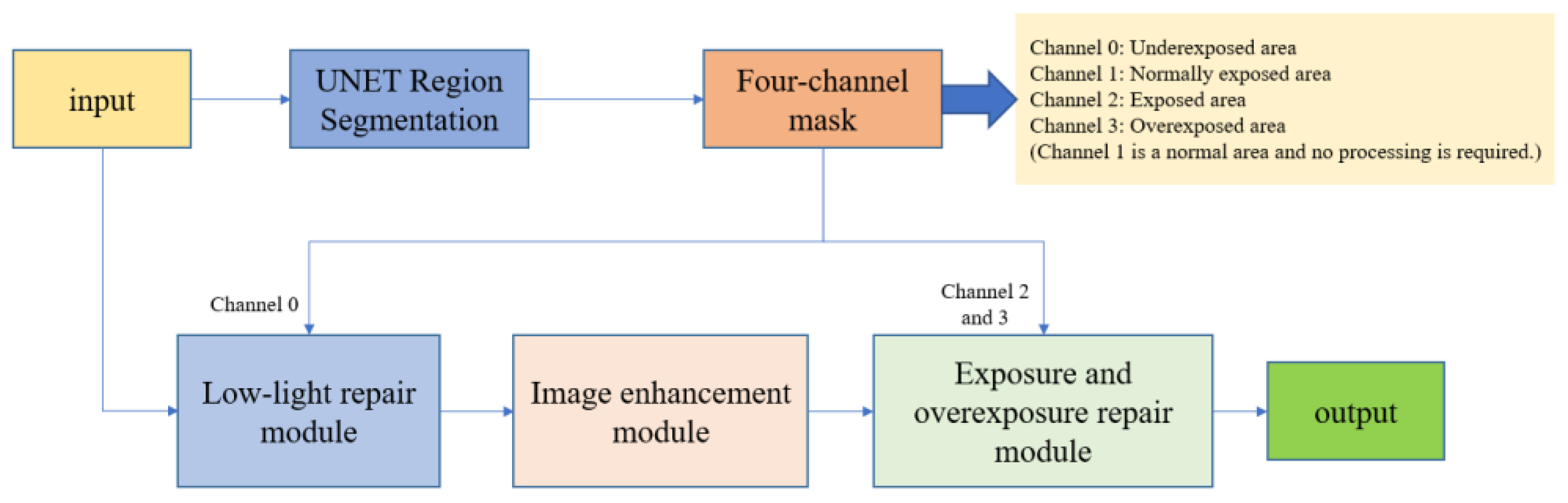
Figure 10.
Degenerate network structure diagram.
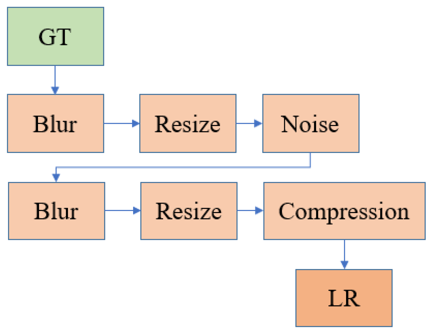
Figure 11.
Structural diagram of the Overexposure and overexposed area repair module.
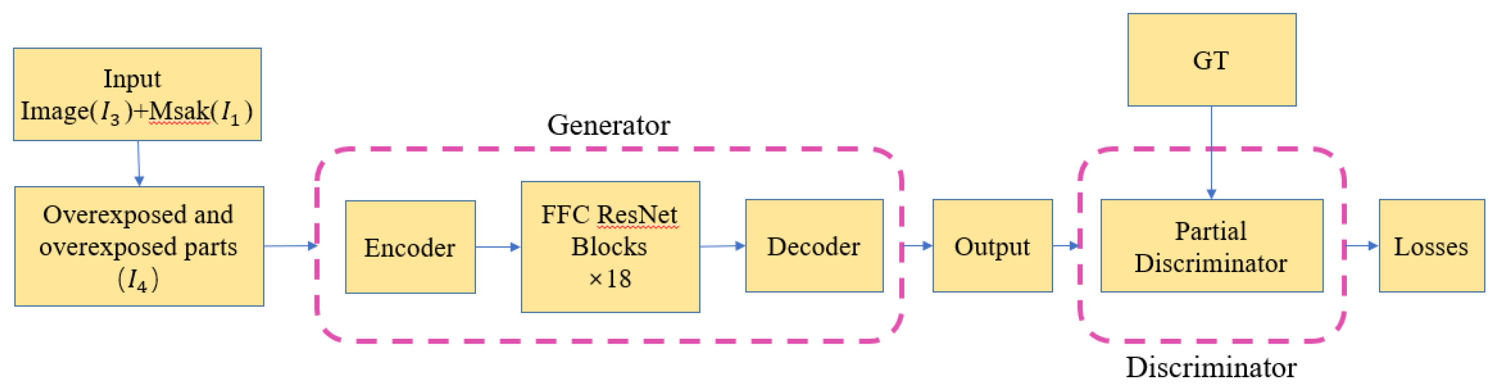
Figure 12.
Encoder Structure Diagram.

Figure 13.
FFC ResNet Blocks Structure Diagram.

Figure 14.
Decoder Structure Diagram.

Figure 15.
Discriminator Structure Diagram.

Figure 16.
Comparison of Effects.
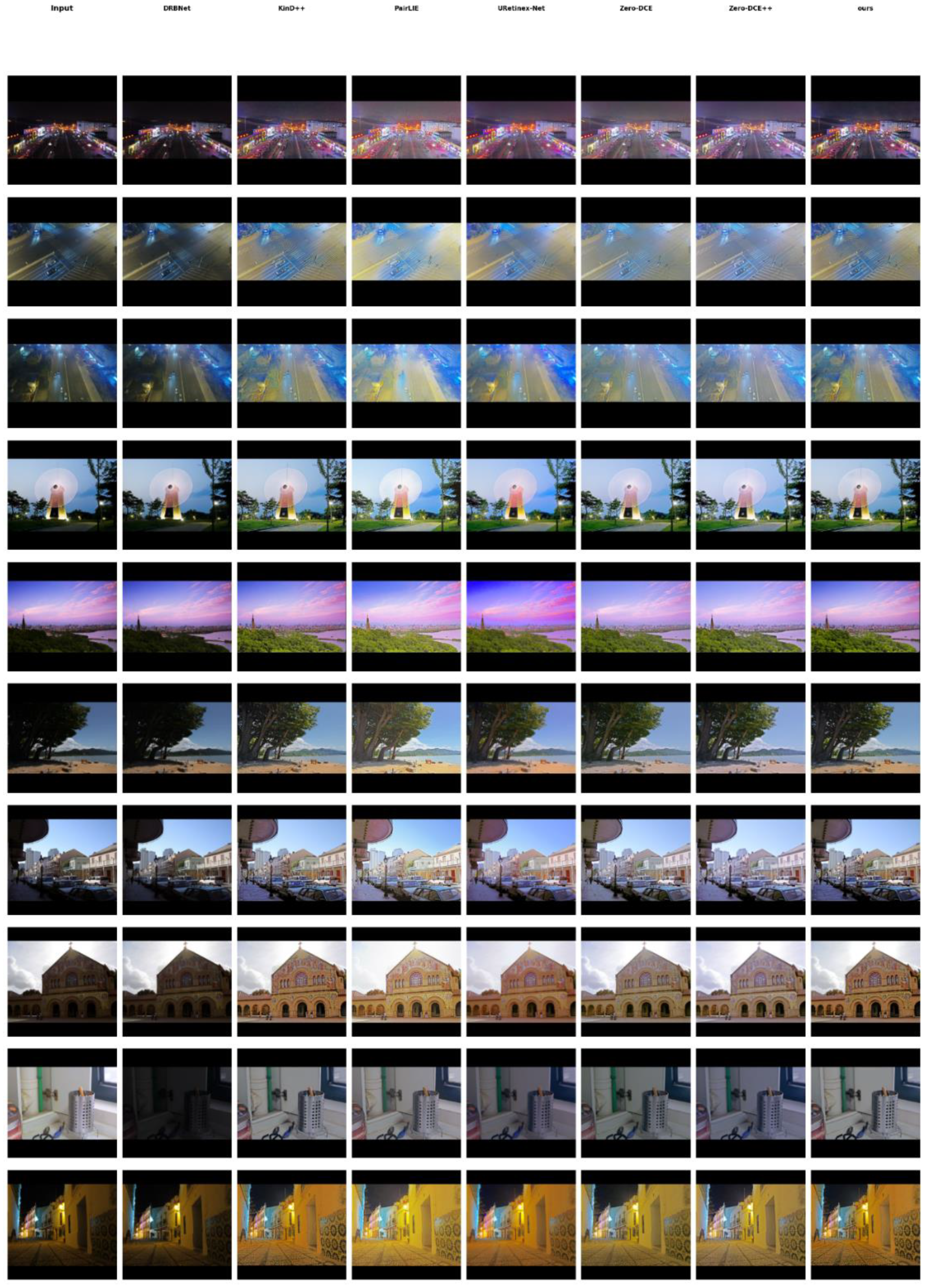
Figure 19.
shows the exposure processing effect.
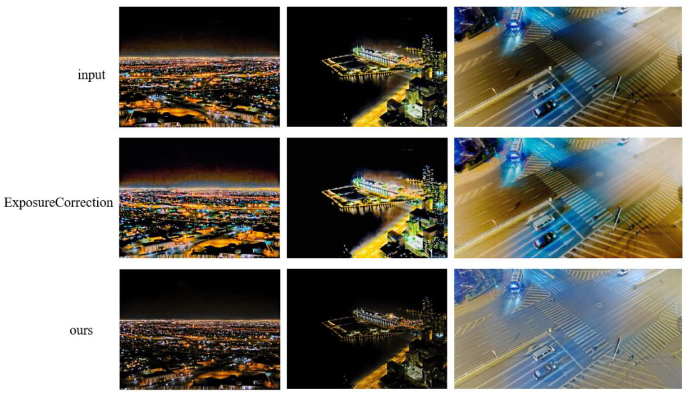
Figure 20.
Comparison of underexposure processing modules.
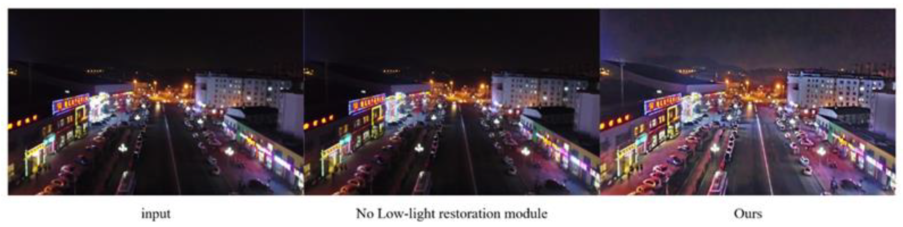
Figure 21.
Comparison of image enhancement modules.
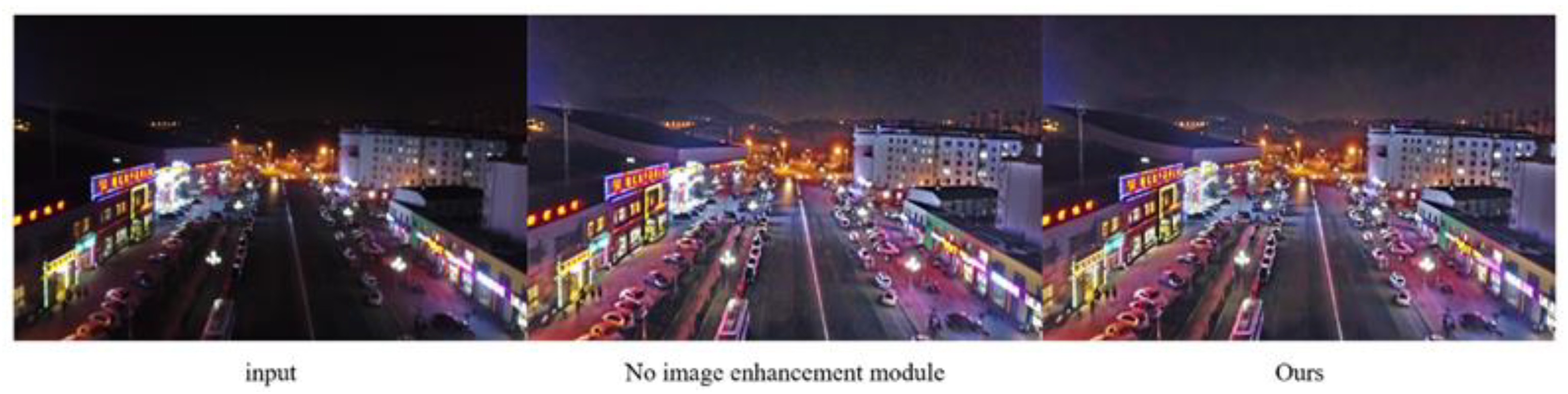
Figure 22.
Comparison of Exposure and Overexposure Modules.
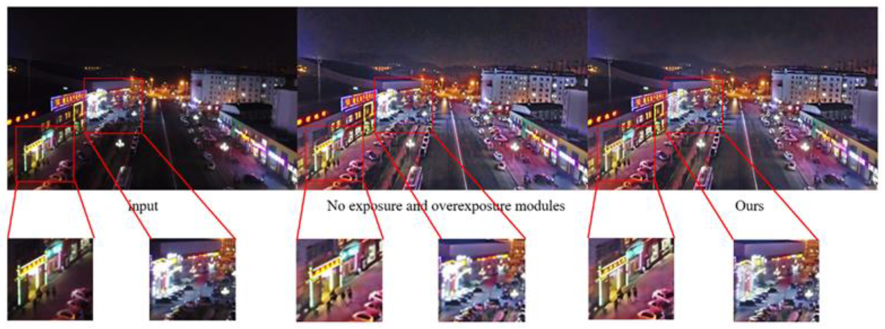

Table 1.
Objective Indicators.
| Method | LOE | BRISQUE | NIQE | Brightness | Contrast | Entropy | Colorfulness |
|---|---|---|---|---|---|---|---|
| DRBNet | 0.113 | 12.542 | 3.944 | 0.255 | 0.146 | 6.631 | 39.042 |
| KinD ++ | 0.172 | 29.919 | 3.322 | 0.448 | 0.127 | 6.838 | 56.744 |
| PairLIE | 0.221 | 34.108 | 4.378 | 0.603 | 0.123 | 6.837 | 64.252 |
| URetinex-Net | 0.117 | 18.111 | 3.492 | 0.480 | 0.122 | 6.729 | 67.524 |
| Zero-DCE | 0.107 | 27.213 | 3.535 | 0.518 | 0.102 | 6.454 | 44.700 |
| Zero-DCE++ | 0.079 | 42.595 | 5.244 | 0.525 | 0.110 | 6.602 | 45.352 |
| ours | 0.166 | 20.940 | 3.950 | 0.440 | 0.132 | 6.810 | 54.04 |
Table 2.
NIQE of different methods on public datasets.
| Method | DICM | LIME | LOL | MEF | NPE |
|---|---|---|---|---|---|
| DRBNet | 4.45 | 4.501 | 6.498 | 4.586 | 4.205 |
| KinD++ | 3.257 | 6.285 | 4.648 | 3.755 | 4.321 |
| PairLIE | 3.584 | 5.146 | 4.278 | 4.261 | 4.954 |
| URetinex-Net | 3.436 | 4.466 | 5.836 | 3.585 | 3.92 |
| Zero-DCE | 3.523 | 4.357 | 7.519 | 3.368 | 3.924 |
| Zero-DCE++ | 4.79 | 6.053 | 5.097 | 6.082 | 5.905 |
| ours | 3.453 | 3.581 | 5.144 | 3.769 | 3.325 |
Disclaimer/Publisher’s Note: The statements, opinions and data contained in all publications are solely those of the individual author(s) and contributor(s) and not of MDPI and/or the editor(s). MDPI and/or the editor(s) disclaim responsibility for any injury to people or property resulting from any ideas, methods, instructions or products referred to in the content. |
© 2026 by the authors. Licensee MDPI, Basel, Switzerland. This article is an open access article distributed under the terms and conditions of the Creative Commons Attribution (CC BY) license (http://creativecommons.org/licenses/by/4.0/).
Copyright: This open access article is published under a Creative Commons CC BY 4.0 license, which permit the free download, distribution, and reuse, provided that the author and preprint are cited in any reuse.