
Submitted:
04 January 2026
Posted:
05 January 2026
You are already at the latest version
Abstract
Classical tool life models, including Taylor’s law, have been extensively used in machining practice due to their simplicity and empirical robustness. However, these formulations neglect the explicit influence of machining vibrations, which become critical in turning operations involving slender workpieces and dynamic cutting conditions. This limitation often leads to significant discrepancies between predicted and experimentally observed tool life. In this study, a vibration-informed extension of Taylor’s tool life law is proposed by explicitly incorporating the maximum transverse displacement of the workpiece as a governing dynamic parameter. The vibration amplitude is obtained from a nonlinear beam model accounting for large deflections and realistic boundary conditions, representative of turning configurations. The dynamic response is evaluated through a semi-analytical formulation and validated experimentally using measured displacement signals during cutting operations. Tool life experiments conducted under varying cutting speeds and vibration levels demonstrate that the proposed model significantly improves prediction accuracy compared to the classical Taylor formulation. The results reveal a strong correla-tion between increased transverse displacement amplitudes and accelerated tool wear, highlighting the critical role of vibration-induced dynamic effects on wear mechanisms. The proposed approach provides a physically grounded framework for coupling machining dynamics and tool wear, offering enhanced predictive capability for tool life estimation in vibration-sensitive turning processes. The findings of this work contribute to a deeper understanding of the interaction between structural dynamics and wear evolution in machining and offer practical insights for process optimization and chatter-aware tool life management.
Keywords:
tool life
; machining vibration
; turning
; nonlinear beam dynamics
; slender workpiece
1. Introduction
Tool wear and tool life prediction remain central issues in machining science due to their direct impact on productivity, surface integrity, and manufacturing cost. Since the pioneering work of Taylor [1], empirical tool life laws have been widely adopted in industrial practice owing to their simplicity and ease of implementation. Among them, Taylor’s tool life equation has become a cornerstone of machining process planning and optimization. Despite numerous extensions and refinements proposed over the past decades, classical tool life models still rely predominantly on cutting parameters such as cutting speed, feed rate, and depth of cut, while neglecting the dynamic nature of the cutting process.
However, machining operations are inherently dynamic systems. Cutting forces, tool-workpiece interaction, and structural flexibility of the machine-tool-workpiece assembly give rise to vibrations that may significantly alter the local cutting conditions. Extensive studies have shown that machining vibrations, particularly in turning of slender workpieces, can strongly affect surface quality, dimensional accuracy, and process stability [2,3,4]. In such configurations, even moderate vibration amplitudes may induce intermittent contact, fluctuating chip thickness, and variable friction conditions at the tool-chip interface, all of which accelerate tool wear mechanisms.
Previous research has addressed tool wear from tribological and thermo-mechanical perspectives, highlighting the roles of adhesion, abrasion, diffusion, and oxidation [5,6,7]. Parallel investigations in machining dynamics have led to advanced models for chatter prediction and stability analysis [8,9,10]. Nevertheless, these two research streams: tool wear modeling and machining dynamics have largely evolved independently. As a result, most existing tool life models do not explicitly account for vibration-related dynamic quantities, but instead rely on indirect indicators or empirical correction factors.
Several attempts have been made to incorporate vibration effects into wear prediction through signal-based monitoring approaches, using acceleration, force, or acoustic emission signals as wear indicators [11,12]. While these approaches are effective for online monitoring, they remain primarily data-driven and do not provide a physically grounded relationship between vibration amplitude and wear evolution. Moreover, they are not readily applicable for predictive tool life estimation during process planning.
From a mechanical standpoint, vibration of slender workpieces during turning can be accurately described using beam theory and nonlinear structural dynamics. Large deflection effects, boundary condition sensitivity, and mode coupling have been shown to significantly influence the dynamic response of beams under external excitation [13,14,15]. Despite the maturity of nonlinear beam models, their direct integration into tool life formulations remains largely unexplored in machining literature.
This gap motivates the present study. The objective of this work is to develop a vibration-informed extension of Taylor’s tool life law by explicitly incorporating the maximum transverse displacement of the workpiece as a governing dynamic parameter. Unlike empirical correction approaches, the proposed formulation relies on a physically meaningful quantity derived from nonlinear beam dynamics, representative of realistic turning configurations. The transverse displacement amplitude is obtained from a semi-analytical nonlinear dynamic model and validated experimentally using displacement measurements acquired during cutting operations.
By coupling machining dynamics and tool wear through a physically grounded parameter, the proposed approach aims to enhance the predictive capability of classical tool life models under vibration-sensitive turning conditions. This contribution is expected to provide deeper insight into the interaction between structural dynamics and wear mechanisms, and to offer practical guidance for chatter-aware process optimization in industrial machining applications.
2. Literature Review
2.1. Classical Tool Life Models and Their Limitations
Tool life prediction has traditionally relied on empirical relationships derived from extensive experimental observations. Taylor’s tool life equation remains the most widely used model due to its simplicity and reasonable accuracy within limited operating ranges [1]. Numerous studies have proposed extensions of Taylor’s law by incorporating additional cutting parameters such as feed rate, depth of cut, cutting environment, and tool geometry [16]. Despite these improvements, the fundamental structure of Taylor-type models remains empirical and does not explicitly capture the physical mechanisms governing tool wear.
More advanced wear models have been developed by incorporating thermo-mechanical effects at the tool–chip interface, including temperature, contact stress, and frictional conditions [17,18]. While these models improve physical realism, they often require detailed input data that are difficult to obtain during process planning. Moreover, their applicability to dynamic machining conditions remains limited, as vibration effects are either neglected or implicitly absorbed into fitting coefficients.
2.2. Tool Wear Mechanisms Under Dynamic Cutting Conditions
Tool wear is governed by a combination of abrasion, adhesion, diffusion, and oxidation mechanisms, whose relative contributions depend on cutting speed, material pair, and contact conditions [6,7]. Under dynamic cutting conditions, these mechanisms are strongly influenced by fluctuating chip thickness and intermittent contact between the tool and the workpiece. Experimental investigations have shown that increased vibration levels accelerate flank wear and crater wear due to repeated load cycling and localized thermal spikes.
Several authors have reported a direct correlation between vibration amplitude and tool wear rate, particularly in turning operations involving flexible workpieces. However, most of these studies focus on qualitative trends rather than predictive modeling, and vibration effects are often characterized using indirect indicators such as acceleration or force signals.
2.3. Machining Dynamics and Vibration Modeling
Machining dynamics has been extensively studied over the past decades, leading to well-established models for chatter prediction and stability analysis [2,8]. Regenerative chatter theory and frequency-domain stability lobe diagrams have become standard tools for selecting stable cutting parameters [3,9]. These models primarily focus on stability boundaries and vibration amplitudes, but do not directly address tool wear evolution.
Recent studies have emphasized the importance of considering structural flexibility and dynamic compliance of the workpiece, especially in turning of slender components. In such cases, the workpiece behaves as a vibrating beam whose dynamic response significantly alters the instantaneous cutting conditions. Linear vibration models may underestimate displacement amplitudes when large deflections occur, motivating the use of nonlinear beam theories.
2.4. Nonlinear Beam Dynamics in Machining Applications
Nonlinear vibration of beams has been thoroughly investigated in structural dynamics, with particular attention to large deflection effects, geometric nonlinearity, and mode coupling [13,19]. Clamped-clamped and cantilever beam configurations have been shown to exhibit amplitude-dependent natural frequencies and complex dynamic responses under harmonic excitation [14,15].
In machining applications, nonlinear beam models have been used to analyze workpiece vibration and chatter phenomena, demonstrating improved accuracy compared to linear formulations [20]. Nevertheless, these models have rarely been exploited to inform tool wear or tool life prediction. The vibration response is typically analyzed independently of wear models, leaving a disconnect between structural dynamics and tool life estimation.
2.5. Tool Wear Monitoring and Vibration-Based Approaches
Vibration-based monitoring techniques have been widely employed for tool condition monitoring, using signal processing and machine learning methods to detect wear states [11,12,21]. While effective for real-time diagnostics, these approaches are inherently reactive and depend on measured signals rather than predictive models. Furthermore, they do not provide a direct analytical relationship between vibration amplitude and tool life, limiting their use in process planning and optimization.
Recent works have attempted to bridge this gap by correlating vibration features with tool wear progression using experimental or data-driven approaches [22]. Although promising, these studies still rely heavily on empirical fitting and lack a clear physical interpretation of the governing parameters.
2.6. Identified Research Gap and Contribution of the Present Work
The literature review highlights a clear gap between machining dynamics modeling and tool life prediction. While both fields are mature, their integration remains limited. Existing tool life models do not explicitly incorporate physically meaningful vibration parameters, and vibration-based wear studies often lack predictive analytical frameworks.
The present work addresses this gap by proposing a vibration-informed extension of Taylor’s tool life law that explicitly incorporates the maximum transverse displacement of the workpiece as a governing parameter. By deriving this displacement from a nonlinear beam dynamic model and validating it experimentally, the proposed approach establishes a direct and physically grounded link between machining vibration and tool wear. This integration represents a novel contribution to the field and aligns with the growing need for predictive, dynamics-aware machining models in advanced manufacturing.
3. Physical Basis and Formulation of the Vibration-Informed Tool Wear Law
3.1. Influence of Workpiece Vibration on Tool-Workpiece Interaction
In conventional tool life formulations, the cutting process is assumed to occur under quasi-steady contact conditions, where the relative position between the cutting edge and the workpiece evolves smoothly as a function of time. Under such assumptions, the dominant wear mechanisms abrasive, adhesive, and diffusion wear are primarily governed by cutting speed, contact pressure, and temperature [1,18,23].
However, when machining flexible or slender components, this assumption becomes invalid. Workpiece vibration introduces time-dependent relative displacements between the cutting edge and the machined surface, fundamentally altering the contact mechanics at the tool-workpiece interface [2,3]. In particular, transverse vibrations normal to the machined surface lead to periodic variations in chip thickness and intermittent contact conditions, even in the absence of self-excited chatter [9].
From a mechanical perspective, these dynamic displacements induce:
- localized fluctuations in normal contact force,
- repeated micro-impacts along the cutting edge,
- cyclic stress concentrations at the tool flank.
Such effects have been shown to promote accelerated flank wear by intensifying abrasive interactions and facilitating micro-crack initiation at the cutting edge. Importantly, the severity of these phenomena is not solely governed by vibration frequency, but rather by the amplitude of the relative displacement, which directly controls the extent of contact interruption and re-engagement [4].
Therefore, the maximum transverse displacement of the workpiece, denoted , emerges as a physically meaningful quantity for characterizing vibration-induced wear acceleration.
3.2. Limitations of Classical Taylor-Type Formulations Under Dynamic Conditions
Taylor’s original tool life law expresses tool durability as a power-law function of cutting speed, implicitly assuming constant cutting conditions throughout the operation [1]. Even in its generalized forms, incorporating feed rate or depth of cut, the model remains fundamentally static, as it does not account for time-varying mechanical interactions at the tool-workpiece interface [18,24].
Under vibratory cutting conditions, two key limitations arise:
- Overestimation of effective cutting time
Due to intermittent contact caused by vibration, the tool experiences repeated periods of intensified mechanical loading that are not reflected in average cutting speed-based formulations. As a result, the cumulative damage per unit time is underestimated by classical models [25].
- Neglect of displacement-driven wear mechanisms
Classical formulations do not distinguish between steady sliding contact and impact-dominated interactions, despite their markedly different effects on wear evolution and edge integrity [23].
Consequently, Taylor-based predictions tend to overestimate tool life when dynamic displacement amplitudes become significant, particularly in turning operations involving beam-like workpieces or low structural stiffness [3].
These limitations motivate the introduction of a corrective mechanism that preserves the simplicity of Taylor’s law while embedding a physically grounded dynamic parameter.
3.3. Conceptual Framework of the Vibration-Informed Wear Law
Rather than redefining tool wear mechanisms from first principles, the present approach adopts a phenomenological extension of Taylor’s law, in which the influence of vibration is incorporated through a displacement-dependent correction. Similar phenomenological strategies have been successfully employed to extend classical machining models toward dynamic regimes without excessive computational complexity [9].
The central hypothesis of this work is that:
The effective wear rate increases monotonically with the maximum transverse displacement of the workpiece, due to intensified mechanical interaction at the tool-workpiece interface.
Accordingly, a modified wear criterion is introduced by defining an effective flank wear threshold, , which accounts for vibration-induced degradation. This threshold is assumed to decrease as the vibration amplitude increases, reflecting the accelerated progression toward tool failure. Such displacement-dependent degradation concepts are consistent with experimental observations reported in vibration-assisted and dynamic cutting studies [4].
By embedding into an otherwise classical tool life framework, the proposed formulation establishes a direct mechanical link between structural dynamics and tool wear evolution, while maintaining analytical transparency and industrial applicability.
The corresponding effective tool life, denoted , is therefore shorter than the tool life predicted under quasi-static conditions.
Figure 1 schematically illustrates the proposed vibration-informed extension of Taylor’s tool life law, highlighting the reduction of the effective wear threshold due to vibration-induced displacement.
3.4. Mathematical Formulation of the Modified Tool Life Law
Based on the above physical considerations, the vibration-informed tool life law is formulated by introducing a displacement-dependent correction term into the classical Taylor relationship.
The effective tool life is expressed as:
where:
- is the tool life predicted by the classical Taylor law,
- is the maximum transverse displacement of the workpiece,
- is a sensitivity coefficient capturing the coupling between vibration amplitude and wear acceleration.
This formula will be used in section 7.5 to calculate .
This formulation preserves the original structure of Taylor’s law while introducing a single additional parameter with a clear physical interpretation. The coefficient reflects the susceptibility of the cutting tool to vibration-induced wear and depends on tool material, workpiece material, and cutting conditions.
Importantly, the proposed formulation avoids arbitrary empirical corrections by relying on a measurable dynamic quantity, , which can be obtained analytically or experimentally.
3.5. Discussion of Model Assumptions and Applicability
Several assumptions underpin the proposed vibration-informed wear law:
- The dominant vibration mode is transverse and normal to the machined surface.
- Wear acceleration is primarily governed by displacement amplitude rather than vibration frequency.
- Thermal effects are implicitly included in the baseline Taylor prediction and not explicitly coupled with vibration.
While these assumptions limit the scope of the model, they enable a clear and tractable formulation suitable for engineering applications. The model is particularly relevant for turning operations involving slender or weakly supported workpieces, where transverse vibration amplitudes are non-negligible.
The generality of the formulation allows extension to other machining configurations by adapting the dynamic model used to compute .
3.6. Transition Toward Analytical and Experimental Validation
To operationalize the proposed wear law, an accurate estimation of the maximum transverse displacement is required. In the present study, this quantity is obtained through a semi-analytical nonlinear beam model, which captures the dynamic response of the workpiece under cutting-induced excitation.
The following sections present:
- the analytical formulation used to compute ,
- the experimental setup employed to measure displacement and tool wear,
- and a quantitative comparison between classical and vibration-informed tool life predictions.
4. Methodology
4.1. Overview of the Proposed Approach
The objective of the proposed methodology is to establish a physically grounded relationship between machining vibration and tool life by extending the classical Taylor tool life law. To achieve this, the vibration amplitude of the workpiece during turning is explicitly introduced as a governing parameter. The methodology consists of three main steps:
- Dynamic modeling of the workpiece using nonlinear beam theory to estimate transverse displacement amplitudes under cutting excitation.
- Experimental measurement and validation of vibration amplitudes during turning operations.
- Formulation of a vibration-informed tool life law, in which the maximum transverse displacement modifies the classical Taylor relationship.
This approach differs fundamentally from signal-based or empirical correction methods, as it relies on a physically interpretable dynamic quantity directly linked to the cutting process.
4.2. Dynamic Modeling of the Workpiece During Turning
4.2.1. Mechanical Representation and Assumptions
In turning operations involving slender workpieces, the workpiece flexibility dominates the dynamic response of the machining system. The workpiece is therefore modeled as a beam subjected to distributed cutting forces acting at the tool-workpiece contact location. Depending on the fixturing configuration, clamped-free or clamped-clamped boundary conditions are considered, which are representative of common industrial turning setups.
The following assumptions are adopted:
- The workpiece material behaves elastically within the vibration amplitude range considered.
- Geometric nonlinearity due to large transverse deflections is accounted for.
- Damping is modeled using an equivalent viscous damping formulation.
- Cutting forces act as external excitation and are modulated by the dynamic displacement of the workpiece.
4.2.2. Governing Equations and Nonlinear Formulation
The transverse vibration of the workpiece is governed by the nonlinear Euler-Bernoulli beam equation, augmented with geometric nonlinearity arising from mid-plane stretching. This formulation captures amplitude-dependent stiffness effects that become significant for large deflections [13,19].
Rather than presenting the full mathematical derivation, the focus is placed on the physical interpretation of the dynamic response. The nonlinear stiffness term leads to a shift in natural frequencies and modifies the steady-state vibration amplitude under cutting excitation. This behavior is particularly relevant in turning, where cutting forces may excite modes close to resonance.
A modal reduction technique is employed to retain the dominant vibration modes, allowing the dynamic response to be expressed in terms of generalized coordinates. The resulting reduced-order model provides an efficient yet accurate estimation of the maximum transverse displacement at the cutting location.
4.3. Estimation of Vibration Amplitude
The primary dynamic quantity extracted from the model is the maximum transverse displacement amplitude, denoted , at the tool-workpiece contact point. This parameter is selected for several reasons:
- It directly affects the instantaneous chip thickness and contact conditions.
- It governs intermittent cutting and load cycling at the cutting edge.
- It has a clear physical interpretation and can be experimentally measured.
Unlike acceleration or frequency-domain indicators commonly used in monitoring studies [11,12], transverse displacement provides a direct measure of geometric deviation during cutting. The steady-state displacement amplitude is obtained by solving the nonlinear dynamic equations under harmonic excitation corresponding to the dominant cutting force component.
4.4. Experimental Validation of the Dynamic Model
To validate the proposed dynamic model, turning experiments are conducted under controlled cutting conditions. Transverse displacement of the workpiece is measured using non-contact sensors positioned near the cutting zone. Cutting parameters are selected to induce different vibration levels while remaining within stable machining conditions.
The experimentally measured displacement amplitudes are compared with model predictions to assess accuracy. Good agreement between numerical and experimental results confirms the ability of the nonlinear beam model to capture the essential dynamic behavior of the workpiece during turning. Similar validation strategies have been successfully adopted in previous machining dynamics studies [3].
4.5. Vibration-Informed Extension of Taylor’s Tool Life Law
4.5.1. Classical Taylor Tool Life Law
4.5.2. Proposed Vibration-Informed Formulation
To account for dynamic effects, the maximum transverse displacement is introduced as an explicit modifying parameter in the tool life equation. Physically, increased vibration amplitude leads to fluctuating contact stresses, thermal cycling, and accelerated wear mechanisms at the cutting edge.
The proposed formulation extends Taylor’s law by incorporating a displacement-dependent term, allowing tool life to decrease as vibration amplitude increases. Unlike purely empirical correction factors, this term is directly linked to a measurable and physically meaningful dynamic quantity derived from the structural response of the workpiece.
4.5.3. Parameter Identification and Model Calibration
The coefficients of the proposed model are identified using experimental tool life data obtained under different cutting speeds and vibration levels. A regression procedure is employed to calibrate the model while preserving the physical structure of the formulation. The resulting parameters reflect the sensitivity of tool life to vibration amplitude and cutting speed.
The experimental procedure set out in Section 6.2 enabled us to measure wear over time for each cutting speed. The results are shown in the following Table 1.
The data in the table above are then represented as experimental curves Figure 2.
Figure 2 illustrates the experimental identification procedure of the vibration sensitivity coefficient by comparing classical and vibration-based wear criteria through linear interpolation of wear curves.
4.6. Methodological Advantages and Scope of Applicability
The proposed methodology offers several advantages over existing approaches:
- It establishes a direct physical link between machining dynamics and tool life.
- It relies on measurable dynamic quantities, enhancing practical applicability.
- It remains compatible with classical tool life formulations, facilitating industrial adoption.
The approach is particularly suited for turning operations involving flexible or slender workpieces, where vibration effects cannot be neglected. While the present study focuses on turning, the methodology can be extended to other machining processes where structural dynamics play a significant role.
5. Experimental Setup and Semi-Analytical Modeling Framework
5.1. Machine Tool and Workpiece Configuration
The experimental investigations were carried out on a TOS TRENCIN SN40C parallel lathe turning center whose structural rigidity is sufficiently high to ensure that the dominant dynamic compliance originates from the workpiece rather than from the machine tool structure. This experimental strategy is commonly adopted in machining dynamics studies aiming to isolate workpiece-induced vibration effects [3].
Figure 3 shows the geometry of the slender workpiece used in the experiments, designed to promote transverse vibration during turning.
The machined parts consisted of cylindrical bars made of an industrially relevant metallic material, selected for its widespread use and well-documented machining behavior. To intentionally promote vibration-sensitive conditions, slender workpieces with high length-to-diameter ratios were employed. Depending on the test configuration, the workpiece was mounted either in a clamped-free or clamped-clamped arrangement using standard chucking and tailstock systems. These boundary conditions are known to strongly affect the dynamic response of the workpiece during turning operations.
This configuration enables controlled excitation of transverse vibrations normal to the machined surface, which directly influence chip thickness variation and tool-workpiece contact conditions.
5.2. Cutting Tools and Machining Parameters
Commercially available cutting inserts with well-defined geometry were used throughout the experimental campaign to ensure repeatability and industrial relevance. The tool material and coating were selected according to the workpiece material and manufacturer recommendations. To isolate the effects of vibration and cutting speed on tool life, tool geometry was kept constant for all tests.
Turning experiments were conducted under dry cutting conditions to avoid additional variability related to coolant-induced thermal effects. Cutting speed was varied over a predefined range in order to generate different tool life levels, while feed rate and depth of cut were maintained constant. This experimental strategy follows classical tool life testing methodologies and allows direct comparison with Taylor-type models [16,26].
5.3. Measurement of Workpiece Vibration
Workpiece vibration was measured in terms of transverse displacement using non-contact displacement sensors positioned close to the cutting zone. Displacement-based sensing was deliberately chosen instead of acceleration measurements, as transverse displacement directly reflects geometric deviation of the workpiece and governs intermittent cutting conditions [11].
Figure 4 presents the experimental turning configuration adopted for transverse displacement measurement.
The sensor signals were acquired at a sufficiently high sampling frequency to capture the dominant vibration modes excited during turning. Signal conditioning and filtering were applied to remove noise and isolate steady-state vibration behavior. Once steady cutting conditions were established, the maximum transverse displacement amplitude, denoted , was extracted from the time-domain signals and used as the primary dynamic indicator.
The non-contact ultrasonic displacement sensor used for vibration measurement is shown in Figure 5.
5.4. Semi-Analytical Modeling of Workpiece Vibration
5.4.1. Modeling Strategy and Mechanical Assumptions
In turning operations involving slender workpieces, the structural behavior of the machined part plays a dominant role in the dynamic response of the cutting system. Under such conditions, the workpiece can be reasonably idealized as a beam-like structure subjected to cutting-induced excitation forces.
In the present study, the workpiece is modeled as a nonlinear elastic beam, whose dynamic behavior is governed by geometric nonlinearity arising from moderately large transverse deflections. This modeling choice is motivated by the need to capture amplitude-dependent stiffness effects that cannot be reproduced by purely linear vibration models [13,14].
The following assumptions are adopted:
- the workpiece material is homogeneous, isotropic, and linearly elastic,
- transverse vibration dominates the dynamic response,
- damping effects are implicitly accounted for through experimental calibration,
- cutting forces act as distributed dynamic excitations along the beam.
These assumptions provide a balanced compromise between physical realism and analytical tractability.
5.4.2. Displacement Field and Nonlinear Dynamic Response
The transverse displacement of the workpiece is approximated using a modal expansion based on admissible shape functions satisfying the imposed boundary conditions. The selected mode shapes correspond to the linear vibration modes of the beam, which provide an efficient basis for capturing the dominant dynamic behavior while maintaining computational efficiency.
Geometric nonlinearity introduces additional axial strain energy associated with large transverse deflections, leading to amplitude-dependent stiffness and modal coupling. This nonlinear behavior is essential for accurately predicting vibration amplitudes under turning conditions, where resonance and near-resonance excitation may occur [15,19].
5.5. Determination of Maximum Transverse Displacement
The key dynamic quantity used in the proposed vibration-informed tool life law is the maximum transverse displacement , defined as the peak value of the transverse displacement over space and time. This quantity directly governs chip thickness fluctuation, contact stress variation, and intermittent cutting phenomena.
The nonlinear governing equations are solved using a semi-analytical approach in which the system mass and stiffness matrices are computed analytically, while time integration is performed numerically. Dedicated computational routines implemented in Fortran are used for solving the dynamic equations, and post-processing is carried out using MATLAB to extract displacement envelopes.
The maximum transverse displacement is then defined as:
This value serves as the dynamic input parameter for the vibration-informed tool life formulation introduced in Section 3.
5.6. Tool Wear and Tool Life Assessment
Tool wear was evaluated by periodically interrupting the cutting tests and inspecting the cutting edge using optical microscopy. Flank wear width was selected as the primary wear criterion, as it is widely adopted in tool life studies and provides a reliable indicator of wear progression [27]. Tool life was defined as the cutting time required to reach a predefined flank wear threshold. For each cutting condition, multiple experiments were performed to assess repeatability and reduce experimental uncertainty. This definition is consistent with classical tool life testing methodologies reported in the literature [1].
5.7. Link Between Modeling and Experimental Validation
The analytically computed values of were systematically compared with experimentally measured displacement amplitudes obtained during turning tests. This comparison serves two complementary purposes: validation of the semi-analytical vibration model and assessment of the predictive capability of the vibration-informed tool life law. The consistency observed between predicted and measured displacement amplitudes confirms that the proposed nonlinear beam model captures the dominant dynamic behavior of the workpiece under cutting excitation. This validated dynamic quantity is subsequently used to correlate vibration amplitude with tool wear evolution and tool life, forming the core of the proposed methodology.
5.8. Experimental Reliability and Limitations
Special care was taken to minimize experimental uncertainty, including sensor alignment errors, tool positioning inaccuracies, and environmental disturbances. Although some variability in tool life measurements is inevitable due to the stochastic nature of wear processes, the observed trends between vibration amplitude and tool life were consistent across repeated tests. While the present setup is specifically designed for turning of slender workpieces, the proposed experimental-numerical framework can be extended to other machining configurations provided that the corresponding dynamic models are appropriately adapted.
6. Experimental Setup and Measurement Methodology
6.1. Objectives of the Experimental Campaign
The experimental campaign was designed to achieve two complementary objectives.
The first objective was to experimentally measure the transverse vibration amplitude of the workpiece during turning operations and to validate the semi-analytical nonlinear dynamic model developed in Section 4. Experimental validation of vibration models is essential, particularly when geometric nonlinearity is involved, as linear formulations are known to underestimate displacement levels under flexible machining conditions [3,13].
The second objective was to quantify tool wear evolution and tool life under vibratory cutting conditions, enabling a direct comparison between classical Taylor-based tool life predictions and the proposed vibration-informed wear law. By combining vibration measurements with wear monitoring, the experimental framework establishes a direct link between workpiece dynamics and tool degradation mechanisms, as recommended in recent machining dynamics studies [7].
To ensure consistency between analytical modeling and experimental observations, cutting conditions and geometric parameters were selected so that the workpiece behavior could be reasonably approximated by a beam-like structure.
6.2. Machine Tool and Cutting Conditions
All turning experiments were performed on a TOS TRENCIN SN40C parallel lathe, equipped with a main spindle power of 6.6 kW. This machine tool provides stable rotational speed control and sufficient structural rigidity, ensuring that the dominant dynamic compliance originates from the workpiece rather than from the machine tool structure. Such a configuration is commonly adopted in vibration-oriented turning studies [28].
The cutting parameters were selected to cover a representative range of industrial turning conditions while maintaining process stability. The following parameters were used:
- Cutting speed : 80 –200 m/min
- Feed rate : 0.3 mm/rev
- Depth of cut : 3 mm
Except for cutting speed, which was varied systematically, all other parameters were kept constant throughout the experimental campaign. This approach allows isolation of the combined influence of cutting speed and vibration amplitude on tool wear and tool life, in line with classical tool life investigation methodologies [16,26].
6.3. Workpiece Material and Geometry
The workpiece material was XC38 medium-carbon steel, a commonly used engineering material characterized by stable machinability and well-documented mechanical properties. Its selection ensures industrial relevance and facilitates comparison with existing tool wear studies [7].
Each workpiece consisted of a cylindrical slender beam with the following dimensions:
- Length
- Diameter
This geometry was intentionally chosen to produce low structural stiffness and promote measurable transverse vibrations during cutting. The workpiece was mounted using a clamped–simply supported configuration through the chuck and tailstock, respectively. These boundary conditions are consistent with the assumptions adopted in the analytical model and are known to strongly influence vibration amplitude during turning of slender parts [19].
6.4. Cutting Tool and Wear Criterion
A single-point turning tool was used throughout the experimental campaign to ensure consistent wear behavior across all tests. Tool geometry, material, and coating were kept constant in order to isolate the effects of vibration amplitude and cutting speed on tool wear.
Tool wear was quantified using the flank wear width , which is widely accepted as a reliable indicator of tool degradation in turning operations and is recommended by international standards [7,27]. Tool life was defined as the cutting time required to reach a predefined flank wear threshold.
Two wear criteria were considered:
Wear measurements were performed at regular intervals using an optical inspection system, allowing accurate tracking of wear progression throughout the cutting process.
6.5. Measurement of Transverse Displacement
6.5.1. Instrumentation
Transverse displacement of the workpiece was measured using an ultrasonic displacement sensor, selected for its non-contact measurement capability and suitability for harsh machining environments. Non-contact displacement sensing is particularly advantageous in vibration studies, as it avoids mass loading effects and mechanical interference with the cutting process [11].
The sensor operates by emitting high-frequency ultrasonic pulses and measuring the time-of-flight of reflected waves from the workpiece surface. This technique enables real-time displacement measurement with adequate spatial and temporal resolution. The sensor was positioned perpendicular to the machined surface at a fixed location corresponding to the region of maximum expected transverse displacement, as predicted by the analytical model.
6.5.2. Data Acquisition and Signal Processing
Displacement signals were acquired using an Arduino-based data acquisition system, providing sufficient temporal resolution to capture vibration-induced motion during turning. Although simple in architecture, such systems have been successfully employed in experimental machining studies when appropriately configured.
Raw displacement signals were processed using MATLAB. Signal processing steps included noise filtering, reconstruction of displacement time histories, and extraction of peak displacement envelopes. The maximum transverse displacement was determined for each cutting condition as the peak value of the filtered displacement signal under steady-state cutting conditions.
6.6. Experimental Procedure and Repeatability
For each cutting speed, the experimental procedure followed a consistent sequence:
- 4.
- Initialization of cutting parameters and verification of tool condition.
- 5.
- Continuous turning operation under constant cutting conditions.
- 6.
- Periodic interruption of cutting for flank wear measurement.
- 7.
- Simultaneous acquisition of displacement signals during cutting.
- 8.
- Termination of the test upon reaching the prescribed wear criterion.
To ensure repeatability, each test was conducted at least twice under identical conditions. The observed variations in measured displacement amplitude and tool life remained within acceptable experimental uncertainty limits, confirming the reliability and consistency of the experimental data.
6.7. Sources of Uncertainty and Experimental Limitations
Several sources of experimental uncertainty were identified, including measurement noise associated with ultrasonic displacement sensing, resolution limits in wear measurement, and minor variability in workpiece material properties. Such uncertainties are inherent to experimental machining studies and have been widely reported in the literature [7].
Despite these sources of scatter, the overall trends relating vibration amplitude to tool life degradation were consistently observed across repeated tests. Importantly, experimental uncertainty does not affect the qualitative and quantitative relationship established between transverse vibration amplitude and accelerated tool wear.
6.8. Transition to Results and Analysis
The experimental methodology described above provides a comprehensive dataset consisting of measured maximum transverse displacement values for each cutting speed, together with corresponding tool wear evolution and tool life data.
These experimental results are compared with analytical predictions in the following section in order to assess the accuracy of the semi-analytical vibration model and to evaluate the effectiveness of the proposed vibration-informed tool life law.
7. Results: Analytical Predictions and Experimental Validation
7.1. Analytical Prediction of Workpiece Vibration Amplitude
The semi-analytical nonlinear beam model introduced in Section 4 was employed to estimate the transverse vibration response of the workpiece under the investigated cutting conditions. For each cutting speed, the governing nonlinear equations were solved numerically to obtain steady-state displacement responses along the beam span.
The computed responses exhibit stable oscillatory behavior dominated by the first transverse bending mode, which is consistent with the dynamic behavior of slender workpieces subjected to cutting-induced excitation [14,15]. As cutting speed increases, the predicted vibration amplitude increases accordingly, reflecting the combined influence of higher cutting force levels and reduced dynamic stability margins, as widely reported in machining dynamics literature [3,19].
From the computed displacement envelopes, the analytically predicted maximum transverse displacement was extracted for each cutting speed. This quantity constitutes the key dynamic input parameter of the vibration-informed tool life law proposed in Section 3.
7.2. Experimental Measurement of Transverse Displacement
Experimental displacement measurements obtained using the ultrasonic sensing system described in Section 5 reveal clear vibration patterns during cutting. The recorded time histories exhibit periodic oscillations with amplitudes characteristic of beam-like transverse vibration, confirming that the selected cutting conditions successfully promote dynamic response of the workpiece.
For each cutting speed, the experimental maximum transverse displacement was extracted from the filtered displacement signals under steady-state cutting conditions. The results show a monotonic increase in displacement amplitude with increasing cutting speed, in agreement with previous experimental observations reported for flexible turning configurations [11].
Importantly, the measured vibration amplitudes remain within the regime of moderately large deflections, thereby justifying the use of a geometrically nonlinear dynamic model rather than a purely linear formulation.
7.3. Comparison Between Analytical and Experimental Vibration Amplitudes
The slight deviations observed at higher cutting speeds can be attributed to effects not explicitly included in the model, such as cutting force fluctuations, local damping variations, and minor deviations in boundary condition stiffness. Similar levels of discrepancy have been reported in comparable vibration modeling studies involving nonlinear beam dynamics under machining excitation [13,15].
This agreement confirms that the semi-analytical nonlinear beam model provides a reliable estimate of the vibration amplitude governing tool-workpiece interaction under the investigated turning conditions.
Table 2 compares analytically predicted and experimentally measured maximum transverse displacement amplitudes for the investigated cutting speeds.
7.4. Tool Wear Evolution and Tool Life Estimation
Tool wear progression was quantified by monitoring flank wear as a function of cutting time for each cutting speed. Based on the experimental wear curves, three tool life values were considered:
- : tool life predicted using the classical Taylor law,
- : tool life predicted using the proposed vibration-informed wear law incorporating ,
- : experimentally observed tool life corresponding to the wear criterion.
Across all cutting speeds, the classical Taylor law systematically overestimates tool life, with increasing deviation as cutting speed and vibration amplitude increase. This behavior highlights the inability of traditional empirical laws to capture vibration-induced wear acceleration, as already suggested in previous studies on dynamic cutting conditions.
In contrast, the vibration-informed wear law yields tool life predictions that are significantly closer to experimental observations, demonstrating the benefit of explicitly accounting for workpiece vibration.
Table 3 provides a consolidated overview of the tool life predictions obtained using the classical Taylor formulation and the proposed vibration-informed wear law, together with the experimentally identified vibration sensitivity coefficient for each cutting speed. A systematic discrepancy is observed between the classical predictions and experimental tool life, with the Taylor-based model consistently overestimating tool life as cutting speed increases. This deviation becomes more pronounced at higher vibration levels, highlighting the limitations of speed-based empirical laws under dynamic machining conditions. In contrast, the vibration-informed formulation yields tool life estimates that are in much closer agreement with experimental observations. The identified vibration sensitivity coefficient exhibits a clear dependence on cutting speed, reflecting the growing influence of dynamic displacement on wear acceleration. These results confirm that vibration amplitude acts as a governing parameter for tool life degradation and validate the relevance of integrating displacement-based dynamic information into tool life modeling.
7.5. Quantitative Assessment of Predictive Accuracy
To quantitatively assess predictive performance, the relative error between predicted and experimental tool life was evaluated for both the classical and vibration-informed models. The results indicate a systematic reduction in prediction error when using the proposed vibration-informed formulation.
Table 4 highlights the improved agreement between experimentally observed tool life and predictions obtained using the vibration-informed model.
The blue curve represents the tool life (Taylor’s law) in minutes. The grey curve represents the true tool life in minutes. The orange curve represents the tool life (new wear law) in minutes.
Figure 6 compares tool life predictions obtained using the classical Taylor law and the proposed vibration-informed formulation against experimental observations.
The improvement becomes more pronounced at higher cutting speeds, where vibration amplitudes increase and dynamic effects dominate tool-workpiece interaction. This trend confirms that vibration amplitude plays an increasingly important role in tool wear evolution under aggressive cutting conditions, a phenomenon that cannot be captured by cutting speed alone [3,7].
7.6. Sensitivity of Tool Life to Vibration Amplitude
An analysis of the sensitivity coefficient reveals a strong dependence of effective tool life on vibration amplitude. Even relatively small increases in lead to noticeable reductions in predicted tool life, emphasizing the nonlinear influence of dynamic displacement on wear progression.
This observation provides experimental support for the central hypothesis of the present study: under dynamic machining conditions, vibration amplitude constitutes a governing factor for tool life degradation, rather than a secondary perturbation. Similar conclusions have been suggested in vibration-related wear studies, although often without a direct displacement-based formulation.
7.7. Summary of results
The key findings of this section can be summarized as follows:
- The semi-analytical nonlinear beam model accurately predicts workpiece vibration amplitudes during turning of slender workpieces.
- Experimental measurements confirm the presence of significant transverse vibration under the investigated cutting conditions.
- Classical Taylor-based tool life predictions systematically overestimate actual tool life in vibration-sensitive regimes.
- The proposed vibration-informed wear law significantly improves predictive accuracy by explicitly incorporating a displacement-based dynamic parameter.
These results provide a solid foundation for the physical interpretation and broader implications discussed in the following section.
8. Discussion
8.1. Physical Interpretation of Vibration-Induced Wear Acceleration
The results clearly demonstrate that workpiece vibration has a systematic and measurable impact on tool wear progression. Under vibratory cutting conditions, the tool-workpiece interface is subjected to repeated micro-interruptions and re-engagements, leading to fluctuating contact forces and localized stress concentrations at the cutting edge.
The displacement-based framework proposed in this study provides a physically meaningful interpretation of this phenomenon. The maximum transverse displacement directly reflects the severity of dynamic contact conditions. Larger displacement amplitudes increase the likelihood of micro-impacts and intermittent cutting, which accelerate flank wear development through intensified mechanical loading and surface fatigue mechanisms [17,29].
This explains why classical Taylor-based models, which implicitly assume quasi-static cutting conditions, tend to overestimate tool life when vibration effects become significant.
8.2. Comparison with Existing Tool Life and Vibration-Related Approaches
Most extensions of Taylor’s law incorporate additional cutting parameters such as feed rate, depth of cut, or temperature effects. While these extensions improve predictive capability under steady-state conditions, they remain insufficient when dynamic effects dominate the machining process [7].
Previous vibration-related wear studies have often relied on empirical correlations or indirect indicators such as acceleration signals or frequency-domain features. In contrast, the present approach introduces a displacement-based parameter derived from structural dynamics, thereby establishing a direct mechanical link between vibration behavior and wear progression.
Moreover, unlike purely data-driven or regression-based approaches, the proposed model relies on analytically computed quantities, which enhances transparency and facilitates adaptation to different machining configurations.
8.3. Role of Nonlinear Dynamic Modeling
The close agreement between analytically predicted and experimentally measured displacement amplitudes highlights the importance of incorporating geometric nonlinearity in dynamic modeling of slender workpieces. Linear vibration models are known to underestimate displacement amplitudes when moderately large deflections occur, particularly at higher excitation levels [13,14].
By capturing amplitude-dependent stiffness effects and modal coupling, the semi-analytical nonlinear beam model provides a more realistic representation of the workpiece response under cutting-induced excitation. Accurate estimation of is therefore essential for reliable tool life prediction in vibration-sensitive machining operations.
8.4. Implications for Machining Practice and Process Optimization
From an industrial perspective, the proposed vibration-informed tool life model offers practical benefits for machining process planning and optimization. By incorporating vibration amplitude into tool life prediction, manufacturers can better anticipate premature tool failure and adjust cutting parameters accordingly.
The approach also provides a rational basis for evaluating vibration mitigation strategies, such as modifying workpiece support conditions, adjusting cutting speeds, or enhancing structural stiffness. These measures can be assessed in terms of their impact on and, consequently, on tool life.
8.5. Model Limitations and Scope of Applicability
While the proposed framework demonstrates clear advantages, certain limitations must be acknowledged. The model focuses primarily on transverse vibration and does not explicitly account for torsional or longitudinal modes, which may become relevant in other machining configurations. Thermal effects are not explicitly coupled with vibration, although they are indirectly included through the baseline Taylor formulation.
The sensitivity coefficient is identified experimentally and may depend on tool material, coating, and workpiece properties. Future studies should investigate the generalization of this parameter across different material combinations and machining processes.
Despite these limitations, the model is well suited for turning operations involving flexible workpieces, where vibration-induced wear plays a dominant role.
8.6. Contribution to Machining Science
This study contributes to machining science by bridging the gap between structural dynamics and tool life prediction. By embedding a physically meaningful dynamic displacement parameter into a classical wear law, the proposed approach advances the understanding of how vibrations influence tool degradation.
Rather than providing an empirical correction, the model offers a transparent and extensible framework that can be expanded to include additional dynamic and thermo-mechanical effects in future research.
Author Contributions
Conceptualization, K.V.H.; methodology, K.V.H.; software, K.V.H.; validation, M.E.B.; formal analysis, K.V.H.; investigation, K.V.H.; writing original draft preparation, K.V.H.; writing review and editing, M.E.B.; supervision, M.E.B.
Funding
This research received no external funding.
Conflicts of Interest
The author declares no conflict of interest.
References
References
- Taylor, F.W. On the Art of Cutting Metals. J. Fluids Eng. 28, 31–279. [CrossRef] [PubMed]
- Tobias, S.A. Machine tool vibration. 1965. [Google Scholar]
- Altintas, Y. Manufacturing automation: Metal cutting mechanics, machine tool vibrations, and CNC design, 2nd ed.; Cambridge University Press, 2012. [Google Scholar] [CrossRef]
- Quintana, G.; Ciurana, J. Chatter in machining processes: A review. Int. J. Mach. Tools Manuf. 2011, 51, 363–376. [Google Scholar] [CrossRef]
- Astakhov, V.P. Tribology of metal cutting. Tribology International 2006, 39. [Google Scholar]
- Childs, T. Friction modelling in metal cutting. Wear 2006, 260, 310–318. [Google Scholar] [CrossRef]
- Grzesik, W. Advanced Machining Processes of Metallic Materials Theory, Modelling, and Applications. 2017. [Google Scholar]
- Altintas, Y.; Weck, M. Chatter stability of metal cutting and grinding. CIRP Annals 2004, 53, 619–642. [Google Scholar] [CrossRef]
- Budak, E.; Altintas, Y. Analytical Prediction of Chatter Stability in Milling—Part I: General Formulation. J. Dyn. Sys. Meas. Control. 1998, 120, 22–30. [Google Scholar] [CrossRef]
- Munoa, J.; et al. Chatter suppression techniques in metal cutting. CIRP Annals 2016, 65, 785–808. [Google Scholar] [CrossRef]
- Dimla, D.E. Sensor signals for tool-wear monitoring in metal cutting operations—a review of methods. International Journal of Machine Tools and Manufacture 2000, 40, 1073–1098. [Google Scholar] [CrossRef]
- Jemielniak, K. Tool and process condition monitoring. Mechanik 2017, 504–510. [Google Scholar] [CrossRef]
- Nayfeh, A.H.; Mook, D.T. Nonlinear oscillations; Wiley, 1979. [Google Scholar]
- Benamar, R.; Bennouna, M.; White, R. The effects of large vibration amplitudes on the mode shapes and natural frequencies of thin elastic structures part I: Simply supported and clamped-clamped beams. J. Sound Vib. 1991, 149, 179–195. [Google Scholar] [CrossRef]
- Azrar, L.; Benamar, R.; White, R.G. Semi-analytical approach to the non-linear dynamic response problem of s–s and c–c beams at large vibration amplitudes part i: general theory and application to the single mode approach to free and forced vi-bration analysis. J. Sound Vib. 1999, 224, 183–207. [Google Scholar] [CrossRef]
- Boothroyd, G.; Knight, W.A. Fundamentals of Metal Machining and Machine Tools, Third Edition; CRC Press, 2005. [Google Scholar]
- Merchant, M.E. Mechanics of the Metal Cutting Process. I. Orthogonal Cutting and a Type 2 Chip. J. Appl. Phys. 1945, 16, 267–275. [Google Scholar] [CrossRef]
- Astakhov, V.P. Book Review: Machining Fundamentals and Recent Advances by J. Paulo Davim, Ed. Int. J. Mach. Mach. Mater. 2010, 8, 433. [Google Scholar] [CrossRef]
- Rao, S.S. Vibration of Continuous Systems; John Wiley & Sons: Hoboken, NJ, 2007. [Google Scholar]
- Insperger, T.; Stepan, G. Semi-discretization for time-delay systems; Springer, 2011. [Google Scholar]
- Teti, R.; Jemielniak, K.; O’donnell, G.; Dornfeld, D. Advanced monitoring of machining operations. CIRP Ann. 2010, 59, 717–739. [Google Scholar] [CrossRef]
- Kuntoğlu, M.; Sağlam, H. Investigation of progressive tool wear for determining of optimized machining parameters in turning. Measurement 2019, 140, 427–436. [Google Scholar] [CrossRef]
- Shaw, M.C. Metal Cutting Principles, 2nd ed.; 2005. [Google Scholar]
- Armarego, E.J.A.; Brown, R.H. The machining of metals; Prentice Hall, 1969. [Google Scholar]
- Denkena, B.; Biermann, D. Cutting edge geometries. CIRP Ann. 2014, 63, 631–653. [Google Scholar] [CrossRef]
- Trent, E.M.; Wright, P.K. Metal Cutting, 4th ed.; 2000. [Google Scholar]
- Tool-life testing with single-point turning tools. ISO 3685; International Organization for Standardization. 1993.
- Altintaş, Y.; Budak, E. Analytical Prediction of Stability Lobes in Milling. CIRP Ann. 1995, 44, 357–362. [Google Scholar] [CrossRef]
- Oxley, P.L.B. Mechanics of machining: An analytical approach to assessing machinability. 1989. [Google Scholar]
Figure 1.
New wear law integrating the effect of vibration.
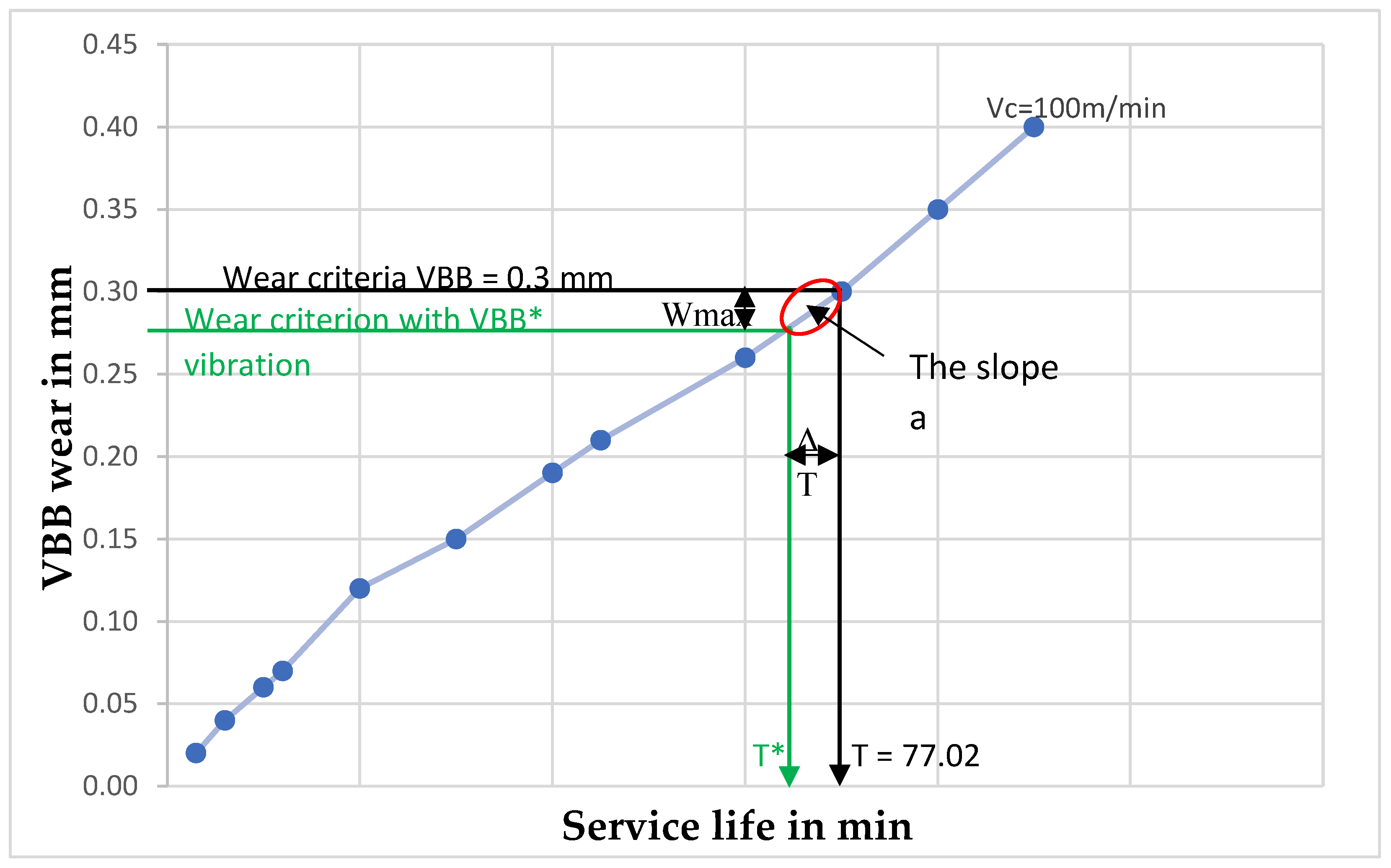
Figure 2.
Wear analysis based on Taylor and vibration criteria.
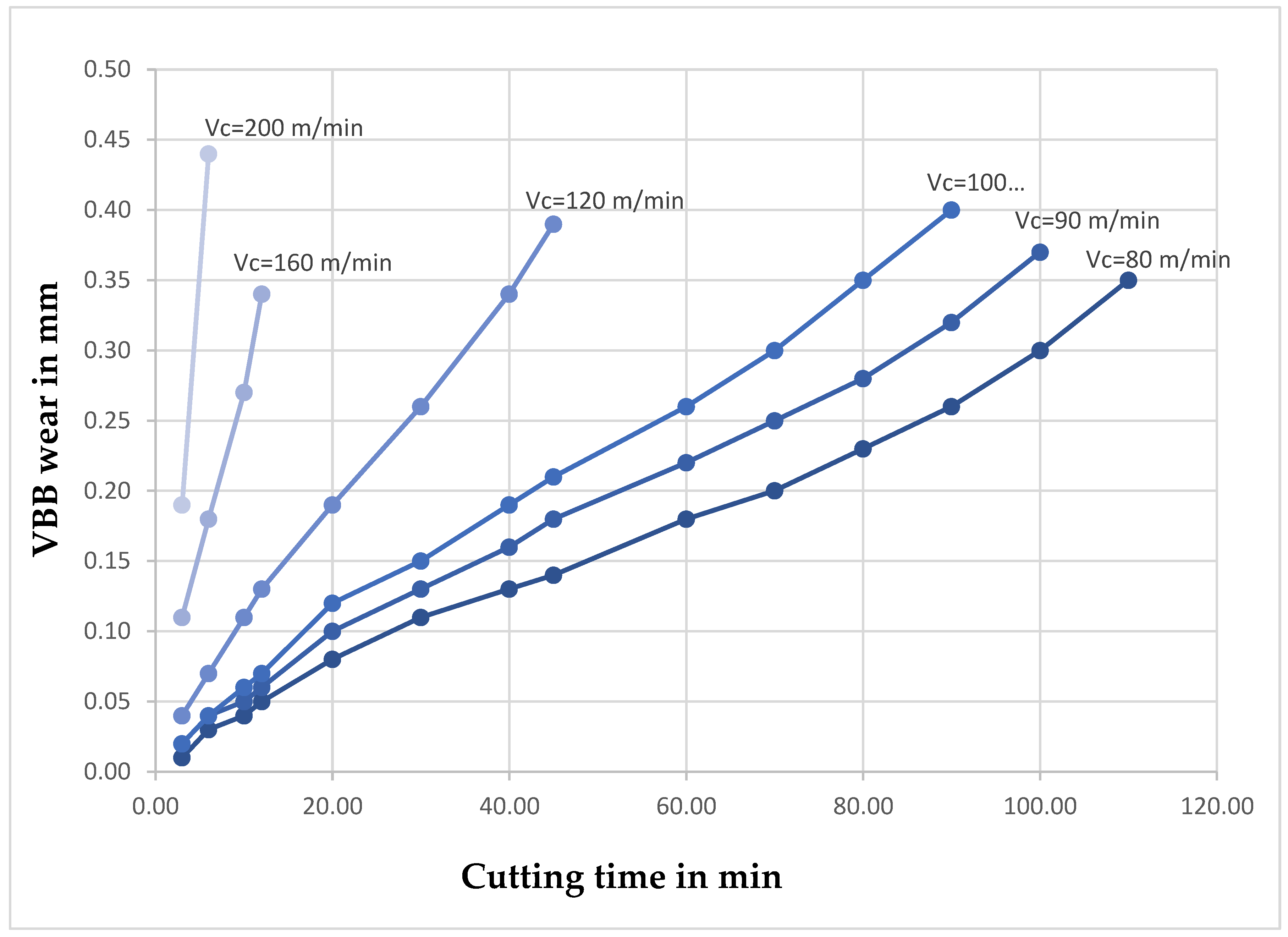
Figure 3.
Circular beam used to calculate displacement.
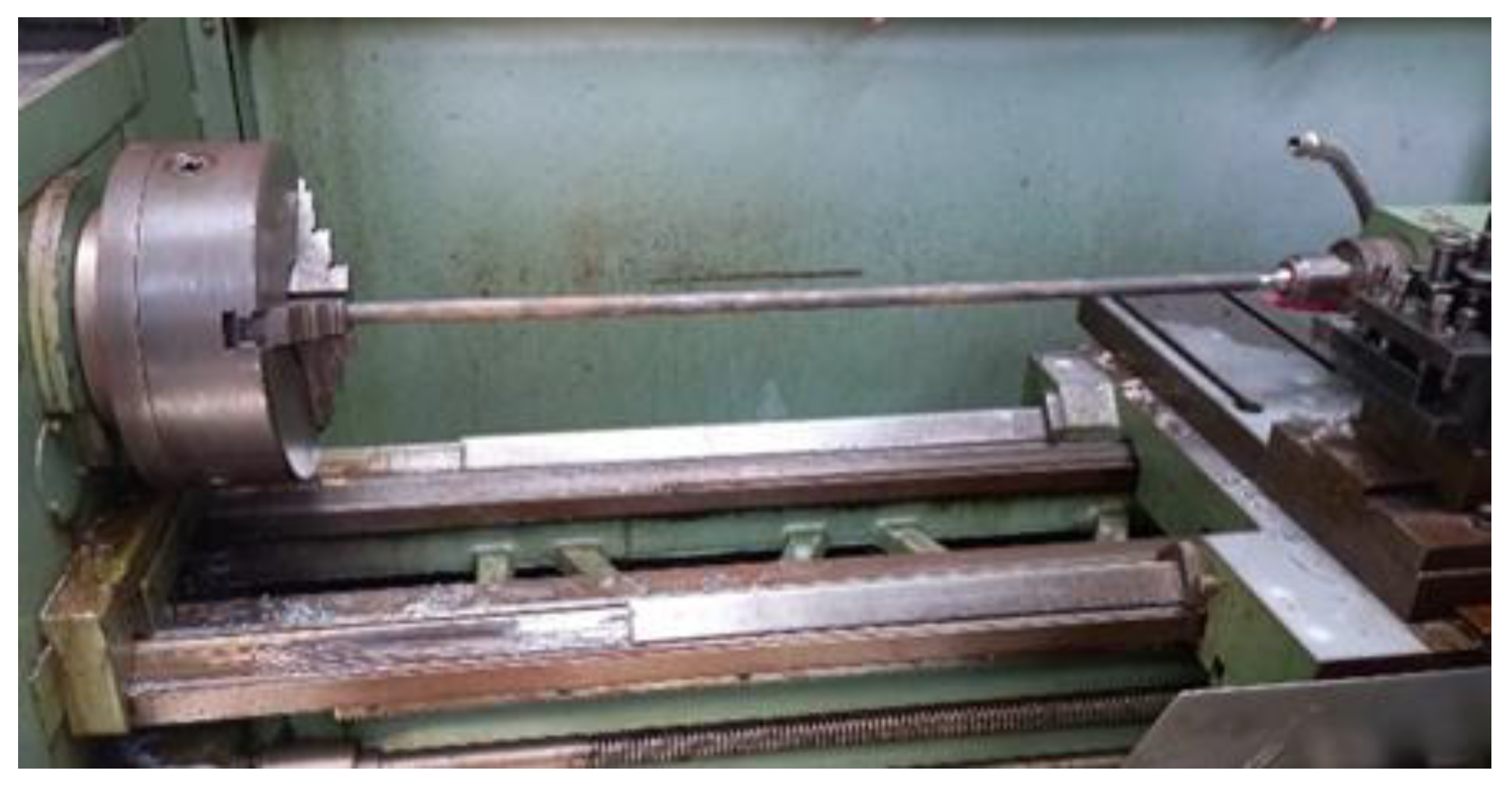
Figure 4.
Description of the experimental protocol.
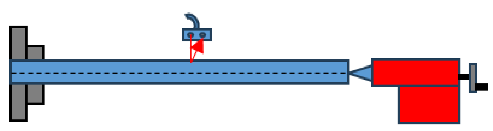
Figure 5.
Ultrasonic sensor.
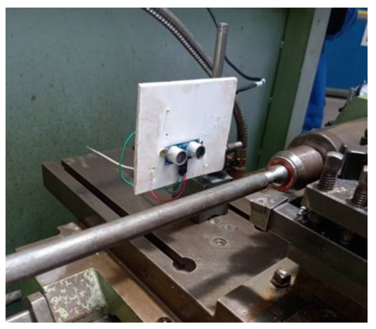
Figure 6.
Comparison Taylor Law and New law.
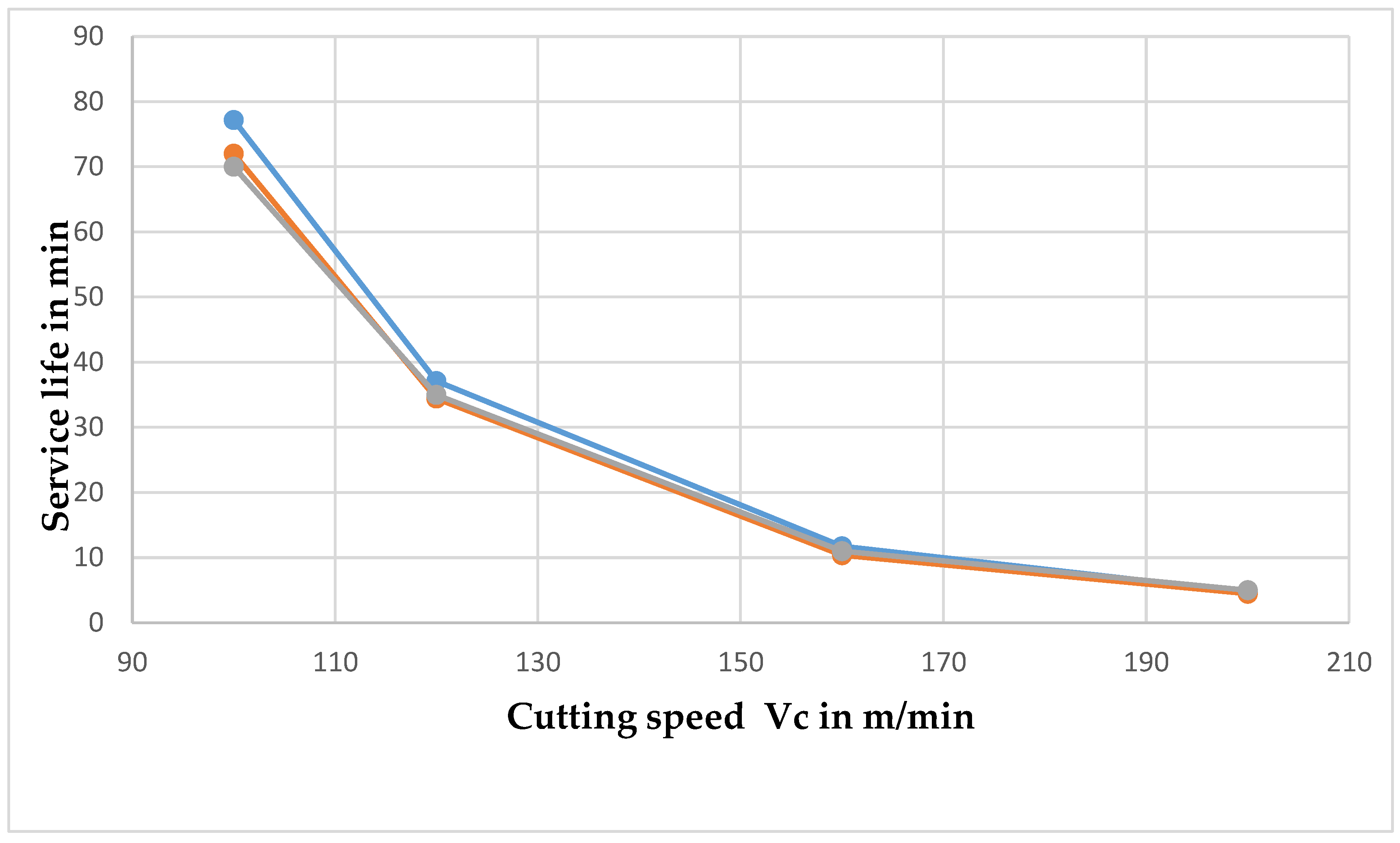

Table 1.
Experimental values for cutting tool wear after machining time.
| Vc1 [80 m/min] |
Vc2 [90 m/min] |
Vc3 [100 m/min] |
Vc4 [120 m/min] |
Vc5 [160 m/min] |
Vc6 [200 m/min] |
||||||
|---|---|---|---|---|---|---|---|---|---|---|---|
| Time [min] | VBB [mm] | Time [min] | VBB [mm] | Time [min] |
VBB [mm] | Time [min] | VBB [mm] | Time [min] | VBB [mm] | Time [min] | VBB [mm] |
| 3,00 | 0,01 | 3,00 | 0,02 | 3,00 | 0,02 | 3,00 | 0,04 | 3,00 | 0,11 | 3,00 | 0,19 |
| 6,00 | 0,03 | 6,00 | 0,04 | 6,00 | 0,04 | 6,00 | 0,07 | 6,00 | 0,18 | 6,00 | 0,44 |
| 10,00 | 0,04 | 10,00 | 0,05 | 10,00 | 0,06 | 10,00 | 0,11 | 10,00 | 0,27 | 10,00 | |
| 12,00 | 0,05 | 12,00 | 0,06 | 12,00 | 0,07 | 12,00 | 0,13 | 12,00 | 0,34 | 12,00 | |
| 20,00 | 0,08 | 20,00 | 0,10 | 20,00 | 0,12 | 20,00 | 0,19 | 20,00 | 20,00 | ||
| 30,00 | 0,11 | 30,00 | 0,13 | 30,00 | 0,15 | 30,00 | 0,26 | 30,00 | 30,00 | ||
| 40,00 | 0,13 | 40,00 | 0,16 | 40,00 | 0,19 | 40,00 | 0,34 | 40,00 | 40,00 | ||
| 45,00 | 0,14 | 45,00 | 0,18 | 45,00 | 0,21 | 45,00 | 0,39 | 45,00 | 45,00 | ||
| 60,00 | 0,18 | 60,00 | 0,22 | 60,00 | 0,26 | 60,00 | 60,00 | 60,00 | |||
| 70,00 | 0,20 | 70,00 | 0,25 | 70,00 | 0,3 | 70,00 | 70,00 | 70,00 | |||
| 80,00 | 0,23 | 80,00 | 0,28 | 80,00 | 0,35 | 80,00 | 80,00 | 80,00 | |||
| 90,00 | 0,26 | 90,00 | 0,32 | 90,00 | 0,4 | 90,00 | 90,00 | 90,00 | |||
| 100,00 | 0,3 | 100,00 | 0,37 | 100,00 | 100,00 | 100,00 | 100,00 | ||||
| 110,00 | 0,35 | 110,00 | 110,00 | 110,00 | 110,00 | 110,00 | |||||
Table 2.
Comparison of experimental and analytical studies as a function of cutting speeds.
| Cutting speed in m/min | Service life (Taylor’s law in min) |
The slope a | displacement in mm |
displacement in mm |
|
|---|---|---|---|---|---|
| 100 | 77.20 | 250 | 0.0208 | 72.00 | 0.02 |
| 120 | 37.14 | 100 | 0.0268 | 34.46 | 0.02 |
| 160 | 11.75 | 45 | 0.0307 | 10.36 | 0.03 |
| 200 | 4.81 | 10 | 0.0321 | 4.489 | 0.03 |
Table 3.
Tool life estimation and vibration sensitivity parameters under different cutting speeds.
|
Cutting speed (m/min) |
No vibration | Cutting speed (m/min) | With vibration | ||
|
Wear |
Service life per Taylor | Wear | Service life | ||
| Vc3 = 100 | 0.3 | 77.20 | Vc3 = 100 | 0.28 | 72.02 |
| Vc4 = 120 | 0.3 | 37.14 | Vc4 = 120 | 0.28 | 35.14 |
| Vc5 = 160 | 0.3 | 11.75 | Vc5 = 160 | 0.28 | 10.85 |
| Vc6 = 200 | 0.3 | 4.81 | Vc6 = 200 | 0.28 | 4.61 |
| Cutting speed (m/min) | Service life by TAYLOR | Service life | Displacement | The slope | |
| Vc3 = 100 | 77.20 | 72.02 | 0.02 | 250 | |
| Vc4 = 120 | 37.14 | 35.14 | 0.02 | 100 | |
| Vc5 = 160 | 11.75 | 10.85 | 0.02 | 45 | |
| Vc6 = 200 | 4.81 | 4.61 | 0.02 | 10 | |
Table 4.
Comparison with real tool life.
| Cutting speed in m/min | Service life (Taylor’s law) in min | (New wear law) in min | |
|---|---|---|---|
| 100 | 77.20 | 72.00 | 72.02 |
| 120 | 37.14 | 34.46 | 35.14 |
| 160 | 11.75 | 10.36 | 10.85 |
| 200 | 4.81 | 4.489 | 4.61 |
Disclaimer/Publisher’s Note: The statements, opinions and data contained in all publications are solely those of the individual author(s) and contributor(s) and not of MDPI and/or the editor(s). MDPI and/or the editor(s) disclaim responsibility for any injury to people or property resulting from any ideas, methods, instructions or products referred to in the content. |
© 2026 by the authors. Licensee MDPI, Basel, Switzerland. This article is an open access article distributed under the terms and conditions of the Creative Commons Attribution (CC BY) license (http://creativecommons.org/licenses/by/4.0/).
Copyright: This open access article is published under a Creative Commons CC BY 4.0 license, which permit the free download, distribution, and reuse, provided that the author and preprint are cited in any reuse.


