
Submitted:
01 January 2026
Posted:
05 January 2026
You are already at the latest version
Abstract
In the current study, we propose a novel reduced-order model for the drag coefficient of a circular cylinder model that can be either fixed or undergoing an oscillatory linear motion in the cross-flow direction, the streamwise direction, or at an arbitrary tilt angle. Thus, the proposed model is not restricted to a single geometric setting of the cylinder. The model establishes a proper nonlinear coupling between the drag coefficient and the lift coefficient, such that the drag coefficient can be restructured using the simple reduced-order model, given the time signal of the lift coefficient. The proposed model is able to capture both the mean component of the drag coefficient, as well as the oscillatory component of it. We derived closed-form expressions to estimate the model parameters from a training dataset. The model was tested and found to be performing satisfactorily under different motion modes. We generated the training data using computational fluid dynamics simulation for a circular cylinder at a low Reynolds number of 300. The computational fluid dynamics solver used was successfully validated by comparison against independent published data. The current study is viewed as a contribution to the fields of nonlinear dynamics, fluid mechanics, and computational mathematics.
Keywords:
dynamical model
; drag coefficient
; reduced-order model
; cylindrical body
; computational fluid dynamics
1. Introduction
The flow over a cylindrical body is commonly encountered in different applications, such as offshore oil risers [1,2], wind turbine towers [3,4,5], solar updraft systems [6,7], overhead power distribution poles [8,9,10], chimneys of power plant and combustion processes [11,12,13], above-ground piping network of gases or liquids [14,15,16], and various structural elements in the buildings sector or the energy sector [17,18,19]. Therefore, theoretical investigations of such a problem have been conducted by several researchers [20,21,22]. Reduced (simplified or low-dimensional) modeling [23,24] allows for faster and less-demanding analysis of this problem, and thus can facilitate further control and design computations [25].
There are several reduced-order models (ROMs) [26,27] for the lift and drag coefficients for a fixed cylinder. These lift and drag coefficients are nondimensionalized forms of the two orthogonal components of the exerted hydrodynamic force due to the time-dependent variations in the near wake. As in other fluid dynamics or gas dynamics applications [28,29], the lift is the force component acting on the cylinder in the cross-stream direction, while the drag is the force component acting on the cylinder in the free-stream direction [30,31]. For convenience and simplified discussion in the current work, we may use the term “lift” or “lift force” to refer to the lift coefficient, and use the term “drag” or “drag force” to refer to the drag coefficient. This should not pose a fundamental concern since either force coefficient is derived from its relevant force component using the same scaling factor [32,33,34], which is ½ ρ U2 D L, where ½ ρ U2 is the dynamic pressure, and D L is the projected area of the cylinder perpendicular to the incoming flow [35,36]. While some of the recent phenomenological reduced-order models (i.e., models that explain one or more observed phenomena) and fully analytical reduced-order models (i.e., models whose parameters are fully related to some variables of the flow case of interest and thus can be systematically estimated) have proved to be very accurate and can even model the transient phase, in addition to the steady-state phase of development of these forces very well, they need to be extended to the moving-cylinder case. In fact, some early attempts to do that go back to 1970 [37,38], and there are existing models that represent the induced lift force for a moving cylinder in a free stream direction (in-line motion) [39,40]. Several of these models focus on the case of a cylinder that moves in the cross-stream direction [41,42], and these models couple this motion to the lift oscillator, which is a nonlinear ordinary differential equation (ODE) [43] representing a self-excited dynamical system [44,45,46], without paying attention to the drag [47,48,49,50,51,52,53,54,55].
Other models that consider the drag force as well as the lift impose a specific coupling between this drag force and the lift force, which is purely quadratic. Another example is the work based on modeling the structural response of elastic cable suspensions, where a model of the drag was introduced and the drag was represented as a function of time and the cable’s longitudinal coordinate in the static condition [56]. In that work, the drag was decomposed into the product of a temporal (time-dependent) function and a spatial (space-dependent) function. The time-dependent function is modeled by a van der Pol equation (cubic nonlinear oscillator) whose linear natural frequency is twice the shedding frequency (which was assumed to be equal to the angular natural frequency of the cable). As in drag-modeling studies for a fixed cylinder, that research work used quadratic coupling between the lift (which is modeled by another van der Pol equation whose linear natural frequency is equal to the shedding frequency) and the drag. Therefore, the two-to-one frequency relationship between the lift and the drag (the fundamental frequency of the oscillatory drag signal is twice the fundamental frequency of the oscillatory lift signal) was assumed in that work. While this assumption is usually acceptable for a wide range of recorded data of VIV (vortex-induced vibration), we show here in the current study that this assumption is not accurate for some types of flows, such as when the cylinder is vibrating at a prescribed tilt angle relative to the free stream [57,58]. We denote such cases when the two-to-one frequency relationship between the lift and drag is not satisfied as “non-traditional wakes”; this is in contrast to the case when this relationship is satisfied, which we denote by “traditional wakes”. Also, the discussed semi-empirical drag model included two empirical constants that were selected and were not well related to the data of interest being modeled (the training dataset). The proposed reduced-order drag model here is fully analytical, meaning that we provide closed-form mathematical expressions to relate its parameters to some variables that are extracted from the training data to be modeled such that good agreement between the reduced-order model (ROM) results and these training data is achieved.
A research team also worked on modeling both the lift and drag forces for fixed and moving cylinders with two degrees of freedom [59]. Instead of using a wake oscillator, they followed a force-decomposition approach, where the lift was assumed to be composed of a main frequency component at the shedding frequency and the odd harmonics, whereas the drag was assumed to be composed of a mean value in addition to a main frequency component at twice the shedding frequency and the even harmonics. For a fixed cylinder, the harmonics were neglected, and one-term lift and one-term drag (in addition to the mean-drag value) were used to represent the signals (time series) of these two fluid forces, which are used to excite the cylinder and move it in both the x and y directions. An earlier reduced-order model (ROM) accounted for the third harmonic of the lift when modeling the lift induced on a fixed cylinder. That drag model is consistent with the one used by another research team in terms of using one harmonic only for the drag of a fixed cylinder. For a moving cylinder, the work described claimed that the harmonics can still be dropped if the shedding frequency is away from the natural frequency of the cylinder, but these harmonics should be retained if the two frequencies are close to each other (i.e., at resonance [60,61]). The coefficients of these harmonics can be obtained from any arbitrary available time-history lift and drag data using auto-regressive moving averaging (ARMA) [62,63,64].
We contribute to this class of problems by extending existing drag reduced-order models (ROMs) that are based on a simple quadratic relationship between the lift and drag, to situations where this relationship does not hold. One of these situations is demonstrated here, which occurs when the cylinder vibrates along directions other than the cross-stream. This can be observed in fluid-structure interaction (FSI) [65,66] or vortex-induced vibration (VIV) [67,68,69] problems, where the oscillatory motion of the cylinder (or cylinder-like element) cannot be restrained to the perpendicular cross-stream direction [70,71,72].
Figure 1 illustrates this generalized situation, where the cylinder undergoes an oscillation that is inclined (i.e., lies between the in-line direction and the cross-stream direction).
The change in the lift-drag relationship is accompanied by other changes in their spectral characteristics. However, these changes are significant for the drag, and thus the available models fail in these cases. When the traditional wake regime and its implied simple two-to-one lift-drag relationship and spectra are restored, the proposed reduced-order model (ROM) [73,74,75] automatically converges to a form that is identical to traditional existing drag models (the extra terms we add in the proposed drag ROM automatically vanish).
Aside from the technical aspect, the current study can be viewed an educational asset and a method for teaching-research nexus [76,77,78]. It exposes college students (at both the undergraduate and the postgraduate levels) to an application of nonlinear dynamics, numerical simulations, and fluid mechanics [79,80,81].
2. Flow Analysis
In order to provide a training dataset of fluid force signals with a drag-lift relationship that does not obey the traditional two-to-one frequency relationship (we need such a dataset to develop and test the new universal reduced-order drag model), and compare its performance to existing drag models that are limited to the case of two-to-one frequency relationship between the lift and drag; we generate this training dataset using computational fluid dynamics (CFD) modeling [82,83,84,85]. For this part, we numerically solve (integrate in time and space) the two-dimensional incompressible Navier-Stokes (NS) equations [86,87,88], which are
In the above equation, u and v are the axial (streamwise) and vertical (cross-flow) components of the fluid flow velocity vector in the x and y coordinates, respectively. The symbol t designates the time, ρ is the fluid density, p is the fluid pressure, and ν is the fluid’s kinematic viscosity. Due to the lack of heat sources or sinks [89], heat transfer mechanisms, thermal radiation [90], temperature-dependent fluid properties [91,92], and high-speed compressible-fluid viscous heating [93], the energy equation is not solved [94,95,96]. This implies a reasonable assumption of isothermal (constant-temperature) cold flow. This is considered a reasonable assumption.
Before the numerical solution, these NS equations are nondimensionalized using the free-stream velocity U, the cylinder diameter D, and twice the dynamic pressure ρU2. We then discretize and solve the resulting system of partial differential equations (PDEs) in the time domain using direct numerical simulation (DNS) [97,98]. We then compute the unsteady flow field around the vibrating cylinder, including the pressure distribution and the shear-stress distribution on its surface.
Although the lift coefficient (CL) and the drag coefficient (CD) for a cylinder should be theoretically obtained through integrating the nondimensional forces over the cylinder’s surface (over circular circumference in the current two-dimensional problem), in computational fluid dynamics (CFD) modeling [99,100], such continuous symbolic integration needs to be discretized and replaced by an quantitative summation process [101]. This transformation is needed because a closed-form analytical solution does not exist for the lift coefficient or the drag coefficient for a cylinder subject to a viscous fluid flow 102,103, although it exists in a very simplified case of potential flows where the viscosity is totally neglected [104], which is referred to as an inviscid flow [105,106], governed by Euler equations [107,108]. Thus, numerical approximation is necessary, and it is achieved by representing the perfectly circular circumference of the cylinder as a series of connected straight-line segments. Each segment is formed by connecting two adjacent grid points located on the cylinder’s surface (circumference). The incremental distances Δx and Δy are the horizontal and vertical projections of the distance between two adjacent grid points on the cylinder surface. Figure 2 illustrates a portion of the cylinder surface between two grid points and shows Δx and Δy.
We numerically integrate the nondimensional pressure coefficient and the nondimensional friction coefficient over the cylinder surface to compute the corresponding nondimensional lift and drag coefficients, which are recorded as two time signals according to
where CP is the time-dependent pressure coefficient (or nondimensional pressure). It is the gauge pressure (the absolute pressure minus the freestream ambient or atmospheric pressure) divided by the dynamic pressure as a scaling factor [109,110,111]. Similarly, Cf is the time-dependent friction coefficient (or nondimensional shear stress). It is the shear stress divided by the dynamic pressure as a scaling factor.
At the present Reynolds number (Re) of 300, the pressure contribution (the first term on the right-hand side of Eq. 2) to the lift and drag coefficients is more significant than the friction contribution (the second term on the right-hand side of Eq. 2). However, we did not neglect the friction term when computing the lift and drag coefficients. It is useful to mention here that the pressure contribution to the lift and drag coefficients arises from the asymmetric pressure distribution over the cylinder’s surface [112]. Vertical asymmetry (deviation between the pressure distribution over the top half of the cylinder and the bottom half of the cylinder) contributes to the lift coefficient, while horizontal asymmetry (deviation between the pressure distribution over the front, upstream half of the cylinder and the rear, downstream half of the cylinder) contributes to the drag coefficient. This pressure asymmetry, in turn, is primarily caused by the low-pressure wake zone formed downstream of the cylinder due to eddies (vortices) [113]. A vortex has a low-pressure zone at its core [114] due to the high spinning speeds developed there, in accordance with Bernoulli’s principle [115] (energy conservation) [116], where pressure energy is converted into kinetic energy, as well as due to the centrifugal effects that pull the spinning fluid outward and establish a suction power. It is also useful to elaborate on the flow regimes over a stationary cylinder based on the Reynolds number. At extremely low Reynolds numbers (Re < 5), reflected by a very slow incoming flow, the flow can be described as “creeping” [117,118]. For such a limiting case, the flow around the cylinder is nearly double-symmetric (having both front-rear symmetry as well as top-bottom symmetry), and no separation of the boundary layer occurs. The creeping flow is laminar and steady, where no irregularities or unsteadiness are observed. This nearly double-symmetric flow regime and double-symmetric pressure distribution cause a cancellation of the pressure effects, leading to vanishing contributions to either the lift coefficient or the drag coefficient. However, the skin friction effect still results in a non-zero drag coefficient. As the Reynolds number increases up to around 40, the boundary layer separates at the downstream side of the cylinder’s surface, and two small vortices (Fopple vortices) develop [119,120], but they remain confined within the near-wake zone rather than being shed away downstream. Thus, this flow regime features a static (steady) separated near-wake region. As the Reynolds number increases further up to around 200, a laminar periodic vortex street is established in the wake. This oscillatory pattern of the flow around the cylinder in its near wake zone causes the lift and drag coefficients to also exhibit an oscillatory behavior. The laminar vortex street gradually transitions into a turbulent one until a fully turbulent vortex street is reached, approximately at a transition threshold Reynolds number [121,122] or critical Reynolds number [123] of 3 × 10⁵ [124]. Up to this Reynolds number, the boundary layer over the unseparated part of the cylinder’s surface is laminar. Laminar boundary layers exhibit relatively weak resistance to separation compared to turbulent boundary layers. This causes the laminar boundary layer to separate early [125], and this enlarges the width of the low-pressure wake. This magnifies the imbalance in the oscillatory pressure distribution, leading to a large contribution to the drag and the lift coefficients. The portion of the drag caused by the pressure imbalance is called form drag or pressure drag. On the other hand, the skin friction effect of a laminar boundary layer is smaller than the skin friction effect of a turbulent boundary layer. This makes the frictional contribution to the drag small compared to the pressure when the Reynolds number is below the transition threshold. As the Reynolds number increases beyond this transition threshold, the boundary layer undergoes a gradual change from a laminar type to a turbulent type, and eventually becomes a turbulent boundary layer. This retards the boundary layer separation, causing the two separation points to move further downstream along the cylinder’s surface, leading to a narrower zone of low-pressure wake. This suppresses the pressure imbalance, and this weakens the influence of the pressure distribution on the lift and drag coefficients. On the other hand, the larger skin friction influence of the turbulent boundary layer increases its contribution to the lift and drag coefficients.
The cylinder undergoes a sinusoidal vibration with a frequency that is equal to the Strouhal frequency (i.e., Ω = ωS) [126,127], and with a prescribed vibrational amplitude. The cylinder’s vibrational motion starts from the beginning of the CFD simulation.
The values of CP and Cf are resolved at the grid points; then, an average value is considered to be applied at the midpoint. These midpoint values are used in Eq. 2 to find CL and CD at every time step after the flow field is resolved. The arbitrary Lagrange Euler (ALE) technique was used to implement the cylinder motion and couple it to the flow solver [128,129,130,131]. In this ALE technique, Eq. 1 is written in an inertial coordinate system (having a global fixed center). Initially, the local cylinder center coincides with this global center. The grid deforms every time step, and it is re-generated algebraically to fit the new fluid region.
Although numerical modeling inevitably involves approximations and errors [132,133], a rigorous numerical approach was followed to ensure that the resolved flow features are physical and do not reflect large numerical errors. Several test cases were performed, which include solving the flow field past a fixed cylinder and a moving cylinder under different simulation parameters (e.g., time step, grid resolution, and grid size) so that we get converged solutions that are satisfactorily independent of these preset parameters that are manually selected rather than automatically derived.
In order to validate the adopted numerical simulation procedure, we performed several calculations in order to reproduce other reported benchmarking results [134] from numerical or experimental studies for both fixed and moving cylinders. For example, we ran a test case at Reynolds number 500 for both fixed and moving cylinders and compared the results with a similar two-dimensional direct numerical simulation of an earlier independent study [135], where they used the spectral element method with ninth-order Gauss-Lobatto-Legendre polynomials [136]. For the fixed cylinder, we got fS = 0.225 (compared to 0.228), time-averaged CD = 1.429 (compared to 1.46), and an amplitude of CL = 1.159 (compared to 1.20). Our values for this case also agree with the measured value of fS = 0.22 [137] and the measured value of time-averaged CD = 1.5 [138]. We also solved the case of a moving cylinder in the cross-stream direction at different frequencies and got similar results as reported by our benchmarking study [135]. In Figure 3, we show the agreement of our results with the reported ones in terms of the limit cycle projection onto the CL–η plane at motion frequencies 0.875 fS and 0.975 fS. The lift response is periodic in both cases.
3. Model Analysis
We start this section by illustrating the quadratic coupling between the drag and lift for the fixed cylinder. Figure 4 shows typical power spectra of the lift and drag coefficients for this case, which we obtained from the numerical simulation. The main component of the lift occurs at fS. We denote this component by a1L. The main component of the drag occurs at twice this frequency; that is why we denote it by a2D (the numeral “2” in the subscript means twice the frequency of the fundamental frequency component of the lift). As a consequence of this two-to-one frequency relationship, the projection of the limit cycle of the wake in the lift-drag plane consists of two loops, as shown in Figure 5. This two-loop pattern was also observed at a higher Reynolds number of 500 [139,140].
Based on this two-to-one frequency relationship, proposed drag models for the fixed cylinder use quadratic coupling terms with the lift [141]. The first proposed model for this category was
The rationale for the above ROM drag model is that it has the least number of necessary terms, which is two. So, it was made as simple as possible as an initial attempt to model the lift-drag coupling. The above ROM is based on the idea of splitting the drag coefficient signal into two independent components. First, there is a constant term (, which is the mean (the time-averaged value or the DC component) of the drag coefficient signal. It is represented by the first term in the above ROM equation. Then, there is the oscillatory component (AC component) of the drag coefficient signal, which has a zero mean. It is represented by the second term in the above ROM equation. Given that the lift and drag are Cartesian force components of the same hydrodynamic force exerted on the cylinder surface, it was considered reasonable in the literature to relate the oscillatory component of the drag to the lift, which is a pure oscillatory signal (has zero mean). In addition, because a two-to-one frequency relationship was observed in the literature between the oscillatory component of the drag and the oscillatory lift, it was decided to model the oscillatory component of the drag as a quadratic function of the oscillatory lift signal. This quadratic dependence can take six forms, namely (), (), (), (), (), and (). Because the phase angle between the oscillatory component of the drag and the oscillatory lift was found in the literature to be near 270°, the last option was considered the most suitable. The multiplier factor of in the second term of the above two-term ROM drag model is added for proper scaling, such that the reconstructed time-domain drag coefficient signal from the ROM equation is close in magnitude to the observed training data for a fixed cylinder.
While the above drag model is able to reproduce the simulated CD in the time domain to a good extent, it cannot reproduce the phase angle between the drag and the lift (i.e., the phase with which a2D leads a1L). Therefore, the ROM represented by Eq. 3 was extended to another amended ROM that has two quadratic terms, as shown in Eq. 4, instead of one term. The weights q1 and q2 are related to the phase angle found in the training dataset. This amended ROM is
In the current study, we aim to extend this amended ROM further such that it holds valid for fixed and moving cylinders with a more general lift-drag relationship than the commonly assumed quadratic one. In the latter case, the two-to-one frequency relationship is distorted. To identify the behavior of the appropriate coupling in these new situations, we analyzed the simulated lift and drag coefficients for a vibrating cylinder at a vibration amplitude of 7.5% D. This value is relatively small for typical problems of VIV (vortex-induced vibration), but we selected it after conducting an extensive amount of CFD simulations at lower and higher amplitudes. Our amplitude selection criterion is the preference for an amplitude value that manifests a wide variety of lift and drag patterns as the motion inclination angle of the cylinder is varied while keeping the amplitude of this motion unchanged. This is important to achieve the aims of the current study and to provide challenging profiles of these forces (i.e., the lift and drag) and their relationship. Lower amplitudes can result in force patterns with a two-to-one relationship (or close). Existing drag models for this type already perform satisfactorily, and we then become unable to demonstrate the usefulness of the proposed new model. On the other hand, higher oscillation amplitudes may result in the dominance of chaotic or quasi-periodic force patterns [142,143,144]. In these cases, the limit cycle is highly distorted, and we then become unable to demonstrate the relationship between the model parameters and the temporal and spectral properties of the lift and drag. The reader is reminded that this study is not concerned primarily with the CFD simulations and numerically resolving the flow field or the lift and drag forces, although it is a large component of the current work. Rather, the CFD simulation conducted here shows how existing reduced-order drag models need to be extended to accommodate cases when the lift and drag relationship does not follow a commonly perceived type for which these models were derived. Also, the CFD simulation provides training datasets for computing the proposed reduced-order model (ROM) for the drag coefficient. We later show several analysis techniques that lead to the proper modifications of these existing reduced-order drag models, and emphasize the influence of the proposed modifications on the modeled results. The proposed reduced-order drag model here contains some parameters that can then be tuned (based on closed-form rigorous analytical expressions, not by trial and error) to other training datasets generated at higher motion amplitudes than the selected 7.5% D. The Reynolds number is maintained at 300, which is adequate here.
We first look at the projection of the limit cycle onto the CL-CD plane and the distortion in the two symmetric loops about the CL = 0 axis. In Figure 6, the motion axis is rotating toward the cross-stream direction as we proceed from case (a) to case (f). The inclination angles of the oscillation line are from 40° in case (a), 50° in case (b), 60° in case (c), 70° in case (d), 80° in case (e), and 90° (thus cross-stream oscillation) in case (f). We show the change of the lift-drag relationship in the projection of the limit cycle onto the plane of their nondimensional coefficients (CL and CD) through this figure. The two-to-one frequency relationship (or the two-loop curve) that existed for the fixed-cylinder case is altered for all cases except for the case of cross-stream motion (the traditional case of one-degree-of-freedom motion). As the motion axis tilts away from the cross-stream direction, the lower loop (negative lift) becomes thinner while the upper loop (positive lift) becomes thicker. Eventually, the lower loop disappears, and we end up with one loop only, as in case (a) within Figure 6. This fact suggests adding a linear coupling of the drag to the lift. In case the two-loop curve is transformed into a multi-loop curve, then a better alternative is to propose a higher-order coupling (e.g., cubic) rather than a lower-order coupling (i.e., linear). This simple tool of graphical analysis for this nonlinear dynamical system revealed a lot of useful details about the dynamics of the problem, and allowed qualitative determination of the appropriate modeling type. However, this elementary analysis should be complemented with a more thorough and quantitative one. For this purpose, we analyze the same lift and drag signals (time series) in the spectral domain and identify the frequency components of each signal. The power spectra of the lift and drag for the cases presented in Figure 6 are shown in Figure 7. Again, case (f) corresponds to a cross-stream oscillatory motion. The spectra of the lift and drag with such a cross-stream motion are qualitatively similar to those obtained for the fixed cylinder (was shown in Figure 4). This confirms what we mentioned earlier about the similarity of the two cases when examined in the lift-drag plane. So, we were able to expose new lift-drag relationship patterns that were not identified before. With a cross-stream motion, the lift is composed of a dominant fundamental lift frequency component (a1L) and its odd harmonics (such as a3L), whereas the drag is composed of a mean quantity (CD, mean) plus a dominant drag frequency component (a2D) and its even harmonics (such as a4D). So, a2L and a1D in this case are very small and can be neglected. As the motion axis tilts away from the cross-stream direction, a1L increases slowly, and a3L and a2D show weak non-monotonic variations. However, a2L and a1D increase rapidly. Since a2L remains about one order of magnitude less than a1L, the distortion of the periodic lift signal is small. In contrast, a1D approaches and even exceeds a2D at some point, which is reflected in the strong deviation in the drag signal from the periodic pattern obtained either with a cross-stream motion or without any motion (a fixed cylinder). Based on the aforementioned findings and analysis, we propose the following extended (we refer to it as “universal”) reduced-order drag model with five terms:
The quadratic terms having the model coefficients q1 and q2 are almost identical to those presented earlier in Eq. 4 for the amended drag ROM, but the Strouhal frequency ωS in Eq. 4 is replaced here by the sinusoidal vibration frequency Ω (both are equal in the current work). The new proposed linear-terms coefficients λ1 and λ2 are determined such that the phase of a1D relative to a1L (we denote this phase angle by ψ[a1D, a1L]) is matched with the training CFD-based value. So
Similarly, the existing coefficients q1 and q2 for the quadratic terms are determined such that the phase of a2D relative to a1L (we denote this phase angle by ψ[a2D, a1L]) is matched with the training CFD-based value. So
In the old reduced-order drag models of Eq. 3 (the primitive two-term drag ROM) and Eq. 4 (the amended three-term drag ROM), the angular shedding frequency ωS appears because for a fixed cylinder [145] (which was the scope of these models), the frequency of the main lift component takes place at this value. However, in the proposed five-term ROM of Eq. 5, we replaced this angular shedding frequency ωS with the angular vibration frequency Ω, which can be different from ωS, although Ω is set to be equal to ωS here, reflecting a locking phenomenon [146,147]. This is to account for the fact that the shedding frequency (and the frequency of the main lift component) when the cylinder vibrates corresponds to the vibration frequency rather than to the Strouhal frequency that pertains to the fixed cylinder, when the wake is not excited by the mechanical vibration.
4. Results
We solve the flow field around a vibrating cylinder by direct numerical simulation (DNS) [148,149,150] of the two-dimensional Navier-Stokes equations at Re 300, which is low enough to justify the two-dimensionality and the use of DNS without turbulence modeling [151,152]. It should be noted that the previous statement does not imply a connection between the dimensionality of the Navier-Stokes equations and the Reynolds number. For example, turbulence (at high Reynolds number) [153] can be investigated using the two-dimensional Navier-Stokes equations [154,155]. On the other hand, laminar flow dynamics (at low Reynolds numbers) can be studied using the three-dimensional Navier-Stokes equations. Instead, we point out that in a real flow regime at Re 300, the three-dimensionality and turbulence exist, but not at a predominant scale [156,157]. The transition from a two-dimensional to a three-dimensional flow field, and from a laminar to a turbulent flow field, happens gradually as the Reynolds number increases. The selected Reynolds number of 300 is viewed as a suitable trade-off between (1) much lower values in which the flow is trivially steady without interesting dynamics, and (2) much larger values in which the complexities of the real flow are partly missed due to the inability of the two-dimensional laminar version of the Navier-Stokes equations to capture them.
The time-dependent lift and drag coefficients are recorded as time signals during each case of computational fluid dynamics (CFD) simulation, and these time signals are obtained after a stable periodic time response is reached.
Spectral analysis is then applied to these signals to evaluate the significant components and their lead angles (relative to a1L). These evaluated spectral parameters of the simulated lift coefficient are used in Eqs. 5~6 to generate a fitted drag-coefficient signal (i.e., obtained by applying the proposed five-term reduced-order drag model after identifying the numerical values of its five parameters through closed-form analytical expressions [158]), which is then compared with the one obtained from the CFD simulation (the training set). We conducted several cases and got a good agreement in them. Some of these cases are discussed next.
In Figure 8, we compare the two drag-coefficient signals (the CFD-simulated and the reduced-order modeled) for the fixed-cylinder case. In this case, a1L = 0.905, a1D = 0.0016, a2D = 0.077, ψ[a1D, a1L] = 256°, and ψ[a2D, a1L] = 335.2°. Consequently, λ1 = –0.241 and λ2 = –0.970; while q1 = 0.908 and q2 = –0.419. The mean drag coefficient (its DC or zero-frequency component) based on the training CFD signal is 1.376. As shown in the figure, the agreement for the drag coefficient is excellent. We would like to add here that the superharmonics in the lift coefficient beyond a3L are negligible, which allows replacing the lift coefficient signal obtained from the CFD simulation with a third-order approximation of the form:
The definitions of ψ[a2L, a1L] and ψ[a3L, a1L] are similar to the definition of ψ[a1D, a1L]. In Figure 9, we compare this harmonic approximation of the lift coefficient to the simulation results, and also the modeled drag coefficient that corresponds to either of the two lift signals. The difference is very small, in fact, which is again due to the insignificance of the neglected superharmonic components in the lift coefficient. Thus, Eq. 8 can be viewed as an algebraic model for the lift coefficient.
In Figure 10, we compare the two drag-coefficient signals for a case where a1D is significant and even larger than a2D. This case corresponds to case (b) in Figure 6~7 (the tilt angle of the mechanical excitation line is 50° from the horizontal free stream), a1L = 0.902, a1D = 0.16, a2D = 0.123, ψ[a1D, a1L] = 223°, and ψ[a2D, a1L] = 352.9°. Consequently, λ1 = –0.736 and λ2 = –0.677; while q1 = 0.992 and q2 = –0.124. The mean drag coefficient (its DC or zero-frequency component) based on the training CFD signal is 1.445. In the same figure, we also show the CL signal (as obtained from the CFD simulation). Again, the fact that the main harmonic of the lift is more than one order of magnitude larger than any of its higher harmonics (superharmonics) minimizes the modulation in the CL signal and makes it close to a pure-harmonic signal. In the same figure, we demonstrate the significance of the added linear-coupling terms by comparing the simulated drag-coefficient signal with the modeled one, but after dropping the linear terms. The disagreement is remarkable, which is a result of assuming a two-to-one frequency relationship between the lift and drag in this case, and such an assumption is not true in this case.
As the motion axis gets closer to the cross-stream, the amplitude a1D decreases, whereas a2D exhibits slight variations. For case (d) in Figure 6~7 (the tilt angle of the mechanical excitation line is 70° from the horizontal free stream), a1D = 0.0796 and a2D = 0.124. Although a2D is larger now than a1D, the contribution of the latter is still important. In Figure 11, we indicate this by comparing the modeled drag-coefficient signal with and without the linear-coupling terms (i.e., with and without accounting for a1D) to the simulated signal. Again, the proposed universal drag model performs very well, whereas the original model (without the extra added terms) shows some level of discrepancy that is less than the one in Figure 10 (due to decreased ratio of a1D/a2D), but it is still considerable.
The final case is for the cross-stream motion, which is case (f) in Figure 6~7. This case does not represent a challenge to the proposed model since the two-to-one frequency relationship between the drag and lift is restored (as was originally the case for a fixed cylinder, before introducing any motion). This explains the big similarity between the modeled drag signal with and without the linear terms, as indicated in Figure 12.
We would like to add that after running the simulations for several cases of interest (i.e., at different tilt angles of the cylinder’s vibration axis), one can fit the various needed spectral quantities for the proposed model, such as a1L and a1D, into suitable functions of the inclination angle, which can be used later to produce the modeled drag signal at any arbitrary inclination angle. This saves time remarkably, knowing that generating the modeled signal takes about three orders of magnitude less time than generating the CFD-based signal. This also allows for analyzing the tilt sensitivity [159,160] of the flow parameters. Similarly, this concept of one-time construction of a lookup table (LUT) or database [161,162] of model parameters can be repeated at different Reynolds numbers of interest or different oscillation amplitudes. After building such a database of parameters, the reduced modeling can be used to conveniently generate interpolated signals within a continuous parameter space.
We also would like to comment on the applicability of the proposed extended drag model in more complex three-dimensional flow regimes (such as in the case of a finite-length cylinder with a high Reynolds number of 106, for example) and whether the two added nonlinear terms in the drag coefficient model are able to explain the drag-lift coupling in such three-dimensional flow dynamics. Due to the three-dimensional nature of such a situation, the signals of either the lift coefficient or the drag coefficient in a real problem become less regular than in the case of simpler two-dimensional flow. However, the three-dimensional flow still shows a coherent vortex street with distinguished frequency components in the lift coefficient [163,164], in a similar manner to the two-dimensional flow problem [165,166]. Therefore, the proposed drag model remains useful in three-dimensional problems.
5. Discussion
Although the current study focuses on reduced-order modeling of the drag coefficient, it can be useful to briefly discuss the reduced-order oscillator model for the lift coefficient also. The current section is devoted to achieving this aim.
Despite the availability of more than one form for modeling the lift coefficient, we consider here one simple form (van der Pol oscillator) [167,168,169] for a fixed cylinder. Such a simple oscillator facilitates the discussion and avoids the extensive details that are involved with a more complicated modeling approach.
A van der Pol oscillator [170,171,172] for the lift coefficient () has the following form:
where is the second time derivative of the lift coefficient, is the Strouhal angular frequency, is a coefficient for linear destabilizing damping [173,174], is the first time derivative of the lift coefficient, and is a coefficient for nonlinear (cubic) stabilizing damping [175,176,177].
At a low value of (and thus ), the nonlinear damping term becomes weaker than the linear destabilizing damping term. Therefore, the lift coefficient tends to be amplified. On the other hand, a high value of (and thus ) causes the nonlinear damping term to be stronger than the linear destabilizing damping term. Therefore, the lift coefficient tends to decay. The opposing influences of the two damping terms lead to a balanced response that is a periodic limit cycle [178,179,180], where the time signal of the lift coefficient oscillates with a fixed amplitude.
6. Conclusions
We considered non-traditional wakes formed as a result of applied mechanical oscillatory perturbations, where the wake of a fixed cylinder is excited by introducing a prescribed vibrational motion along an inclined straight line that lies between the cross-stream direction and the stream-wise direction. This revealed new types of the relationship between the induced lift and drag forces acting on the cylinder. The typical quadratic lift-drag coupling alone fails to reproduce this relationship. We first analyzed different lift and drag signals obtained from computational fluid dynamics (CFD) simulations. The analysis techniques were in the time domain (time series analysis), the frequency domain (spectral analysis), and the lift-drag plane (limit cycle projection). Our observation that the two-loop curve of the lift-drag projection of the limit cycle gradually transforms into a single-loop curve suggested that additional linear lift-coupling terms in the drag reduced-order model (ROM) are needed, especially when the previously neglected component of the drag coefficient at the frequency of the main lift component (a1D) increases. We added two linear terms to an existing three-term drag ROM so that it is extended and can handle non-traditional wake cases where the two-to-one frequency relationship between the drag and lift is broken. We related the model parameters to the spectral variables of the lift and drag signals. We performed several tests of the proposed five-term universal drag model, including the fixed cylinder case and the cross-stream vibration case. These two special cases exhibit a two-to-one frequency relationship between the drag and lift. We also performed tests of the proposed five-term algebraic drag model for cases where the drag has significant components at the motion frequency in addition to the typical component at twice this frequency, so both linear and quadratic couplings become important. All the comparisons showed excellent agreement between the proposed algebraic reduced-order drag model and the time-consuming CFD simulations, which require solving the Navier-Stokes equations that govern the flow field.
Author Contributions
OM was in charge of the methodology, software, validation, formal analysis, investigation, visualization, writing of the original draft, and writing of the revised version. All authors have read and agreed to the published version of the manuscript.
Funding
This research received no funding.
Data Availability Statement
Not applicable (the data that support the findings of this study are available within the article itself).
Acknowledgments:
Conflicts of Interest
The author declares that they have no competing interests.
Ethics Approval and Consent to Participate: Not applicable (this research does not involve human participants, human data, human tissue, animal subjects, or environmental hazards).:.
Consent for Publication: Not applicable (this manuscript does not contain data from any individual person).
Nomenclature (Greek Letters First)
| η | Cross-stream displacement of the cylinder (expressed as a fraction of the cylinder diameter D) |
| ν | Kinematic viscosity of the fluid, ν = μ/ρ |
| ρ | Density of the fluid |
| μ | Dynamic viscosity of the fluid |
| Ω | Nondimensional angular frequency of the applied exciting harmonic vibration of the cylinder |
| ωS | Nondimensional Strouhal angular frequency (for a fixed cylinder), ωS = 2 π fS |
| ψ | Phase angle (angle of a frequency component relative to a1L) |
| a1L | Frequency component of CL at ωS (or Ω) |
| a2L | Frequency component of CL at 2 ωS (or 2 Ω) |
| a3L | Frequency component of CL at 3 ωS (or 3 Ω) |
| a1D | Frequency component of CD at ωS (or Ω) |
| a2D | Frequency component of CD at 2 ωS (or 2 Ω) |
| CD | Drag coefficient (time-dependent) |
| Cf | Friction coefficient (time-dependent) |
| CL | Lift coefficient (time-dependent) |
| CP | Pressure coefficient (time-dependent) |
| D | Diameter of the cylinder |
| L | Length of the cylinder (L =1 for the present two-dimensional flows) |
| fS | Nondimensional Strouhal cyclic frequency (for a fixed cylinder) |
| p | Pressure |
| Re | Reynolds number, Re = ρ U D/μ = U D/ν |
| U | Free-stream velocity |
References
- Odru, P.; Poirette, Y.; Stassen, Y.; Saint Marcoux, J. F.; Abergel, L. Composite Riser and Export Line Systems for Deep Offshore Applications; American Society of Mechanical Engineers Digital Collection, 2009; pp. 147–156. [Google Scholar] [CrossRef]
- Pinto, A.; Broglia, R.; Di Mascio, A.; Campana, E. F.; Rocco, P. Numerical Investigation of the Unsteady Flow at High Reynolds Number Over a Marine Riser With Helical Strakes; American Society of Mechanical Engineers Digital Collection, 2008; pp. 587–595. [Google Scholar] [CrossRef]
- Marzouk, O. Proposed 2MW Wind Turbine for Use in Thumrait, Dhofar, Sultanate of Oman. Journal of Sustainable Energy Engineering 2019, 6(4), 252–270. [Google Scholar] [CrossRef]
- Pierella, F.; Sætran, L. Wind Tunnel Investigation on the Effect of the Turbine Tower on Wind Turbines Wake Symmetry. Wind Energy 2017, 20(10), 1753–1769. [Google Scholar] [CrossRef]
- Marzouk, O. A.; Al Badi, O. R. H.; Al Rashdi, M. H. S.; Al Balushi, H. M. E. Proposed 2MW Wind Turbine for Use in the Governorate of Dhofar at the Sultanate of Oman. Science Journal of Energy Engineering 2019, 7(2), 20–28. [Google Scholar] [CrossRef]
- Harris, R. L. A Numerical Analysis of the Flow Field Surrounding a Solar Chimney Power Plant. Master of Science in Engineering; Stellenbosch: University of Stellenbosch, University of Stellenbosch: South Africa, 2004. Available online: http://hdl.handle.net/10019.1/16337 (accessed on 2025-06-05).
- Gondchawar, A.; Kanabar, B.; Bhoraniya, R. Comprehensive Review of Hybrid Solar Updraft Tower Power Generation Systems for Electricity Production in Tropical Regions. Int J Energ Water Res 2025, 9(4), 2849–2869. [Google Scholar] [CrossRef]
- Papailiou, K. O. Overhead Lines. In Springer Handbook of Power Systems; Papailiou, K. O., Ed.; Springer: Singapore, 2021; pp. 611–758. [Google Scholar] [CrossRef]
- MacIver, C.; Cruden, A.; Leithead, W. E.; Bertinat, M. P. Effect of Wind Turbine Wakes on Wind-Induced Motions in Wood-Pole Overhead Lines. Wind Energy 2015, 18(4), 643–662. [Google Scholar] [CrossRef]
- Zhang, L.; Chen, C.; Yang, Y.; Niu, K.; Xu, W.; Wang, D.; Zhang, L.; Chen, C.; Yang, Y.; Niu, K.; Xu, W.; Wang, D. Anti-Overturning Performance of Prefabricated Foundations for Distribution Line Poles. Buildings 2025, 15(15). [Google Scholar] [CrossRef]
- John, A. D.; Gairola, A.; Ganju, E.; Gupta, A. Design Wind Loads on Reinforced Concrete Chimney—An Experimental Case Study. Procedia Engineering 2011, 14, 1252–1257. [Google Scholar] [CrossRef]
- Sun, Y.; Li, Z.; Sun, X.; Su, N.; Peng, S. Interference Effects between Two Tall Chimneys on Wind Loads and Dynamic Responses. Journal of Wind Engineering and Industrial Aerodynamics 2020, 206, 104227. [Google Scholar] [CrossRef]
- Marzouk, O. A.; Al Kamzari, A. A.; Al-Hatmi, T. K.; Al Alawi, O. S.; Al-Zadjali, H. A.; Al Haseed, M. A.; Al Daqaq, K. H.; Al-Aliyani, A. R.; Al-Aliyani, A. N.; Al Balushi, A. A.; Al Shamsi, M. H. Energy Analyses for a Steam Power Plant Operating under the Rankine Cycle. In First International Conference on Engineering, Applied Sciences and Management (UoB-IEASMA 2021); Al Kalbani, A. S., Kanna, R., EP Rabai, L. B., Ahmad, S., Valsala, S., Eds.; IEASMA Consultants LLP: Virtual, 2021; pp 11–22.
- Marzouk, O. A. Expectations for the Role of Hydrogen and Its Derivatives in Different Sectors through Analysis of the Four Energy Scenarios: IEA-STEPS, IEA-NZE, IRENA-PES, and IRENA-1.5 °C. Energies 2024, 17(3), 646. [Google Scholar] [CrossRef]
- Easter, N.; Gao, M.; Krishnamurthy, R. M.; Kompally, S.; Coates, T. Implication of Fractographic Analysis of the Crack in an Above Ground Pipeline—Potential Role of Hydrogen. OnePetro 2022. [Google Scholar]
- Marzouk, O. A. 2030 Ambitions for Hydrogen, Clean Hydrogen, and Green Hydrogen. Engineering Proceedings 2023, 56(1), 14. [Google Scholar] [CrossRef]
- Marzouk, O. A. Solar Heat for Industrial Processes (SHIP): An Overview of Its Categories and a Review of Its Recent Progress. Solar 2025, 5(4), 46. [Google Scholar] [CrossRef]
- Buckling of Thin Metal Shells; Teng, J. G., Rotter, J. M., Eds.; CRC Press: London, UK, 2006. [Google Scholar] [CrossRef]
- Betancourt-Tovar, M.; Cuan-Urquizo, E.; Roman-Flores, A. Design and Micro-Mechanics Characterization of Additively Manufactured Architected Cylindrical Structures. International Journal of Mechanical Sciences 2025, 294, 110199. [Google Scholar] [CrossRef]
- Al Manthari, M. S.; Azeez, C.; Sankar, M.; Pushpa, B. V. Numerical Study of Laminar Flow and Vortex-Induced Vibration on Cylinder Subjects to Free and Forced Oscillation at Low Reynolds Numbers. Fluids 2024, 9(8), 175. [Google Scholar] [CrossRef]
- Lamont, P. J.; Hunt, B. L. Out-of-Plane Force on a Circular Cylinder at Large Angles of Inclination to a Uniform Stream. The Aeronautical Journal 1973, 77(745), 41–45. [Google Scholar] [CrossRef]
- Civrais, C. H. B.; White, C.; Steijl, R. Influence of Anharmonic Oscillator Model for Flows over a Cylindrical Body. AIP Conference Proceedings 2024, 2996(1), 080008. [Google Scholar] [CrossRef]
- Marzouk, O. A. Detailed and Simplified Plasma Models in Combined-Cycle Magnetohydrodynamic Power Systems. International Journal of Advanced and Applied Sciences 2023, 10(11), 96–108. [Google Scholar] [CrossRef]
- Constante-Amores, C. R.; Linot, A. J.; Graham, M. D. Dynamics of a Data-Driven Low-Dimensional Model of Turbulent Minimal Pipe Flow. Journal of Fluid Mechanics 2025, 1020, A58. [Google Scholar] [CrossRef]
- Marzouk, O. A.; Nayfeh, A. H. Control of Ship Roll Using Passive and Active Anti-Roll Tanks. Ocean Engineering 2009, 36(9), 661–671. [Google Scholar] [CrossRef]
- Marzouk, O. A. Reduced-Order Modeling (ROM) of a Segmented Plug-Flow Reactor (PFR) for Hydrogen Separation in Integrated Gasification Combined Cycles (IGCC). Processes 2025, 13(5), 1455. [Google Scholar] [CrossRef]
- Zhang, W.; Kou, J.; Wang, Z. Nonlinear Aerodynamic Reduced-Order Model for Limit-Cycle Oscillation and Flutter. AIAA Journal 2016, 54(10), 3304–3311. [Google Scholar] [CrossRef]
- Bishop, R. E. D.; Hassan, A. Y. The Lift and Drag Forces on a Circular Cylinder in a Flowing Fluid. Proceedings of the Royal Society of London. Series A. Mathematical and Physical Sciences 1997, 277(1368), 32–50. [Google Scholar] [CrossRef]
- Marzouk, O. A. Urban Air Mobility and Flying Cars: Overview, Examples, Prospects, Drawbacks, and Solutions. Open Engineering 2022, 12(1), 662–679. [Google Scholar] [CrossRef]
- Vickery, B. J. Fluctuating Lift and Drag on a Long Cylinder of Square Cross-Section in a Smooth and in a Turbulent Stream. Journal of Fluid Mechanics 1966, 25(3), 481–494. [Google Scholar] [CrossRef]
- Kim, Y.; Kim, D.-M.; Roh, T.-S.; Lee, H. J. Drag Reduction Effect by Counter-flow Jet on Conventional Rocket Configuration in Supersonic/Hypersonic Flow. Journal of Aerospace System Engineering 2020, 14(4), 18–24. [Google Scholar]
- Massaro, D.; Karp, M.; Jansson, N.; Markidis, S.; Schlatter, P. Direct Numerical Simulation of the Turbulent Flow around a Flettner Rotor. Sci Rep 2024, 14(1), 3004. [Google Scholar] [CrossRef]
- Esmaeili, M.; Fakhri Vayqan, H.; Rabiee, A. H. Impact of Temperature-Induced Buoyancy on the 2DOF-VIV of a Heated/Cooled Cylinder. Arab J Sci Eng 2025, 50(4), 2807–2822. [Google Scholar] [CrossRef]
- Nagata, T.; Shigeta, T.; Kasai, M.; Nonomura, T. Schlieren Visualization and Drag Measurement on Compressible Flow over a Circular Cylinder at Reynolds Number of $$\mathcal {O}(10^2)$$. Exp Fluids 2025, 66(5), 91. [Google Scholar] [CrossRef]
- Sridhar, M. K.; Kang, C.-K.; Landrum, D. B.; Aono, H.; Mathis, S. L.; Lee, T. Effects of Flight Altitude on the Lift Generation of Monarch Butterflies: From Sea Level to Overwintering Mountain. Bioinspir. Biomim. 2021, 16(3), 034002. [Google Scholar] [CrossRef]
- Kharrouba, M.; Pierson, J.-L.; Magnaudet, J. Flow Structure and Loads over Inclined Cylindrical Rodlike Particles and Fibers. Phys. Rev. Fluids 2021, 6(4), 044308. [Google Scholar] [CrossRef]
- Hartlen, Ro. T.; Currie, I. G. Lift-Oscillator Model of Vortex-Induced Vibration. Journal of the Engineering Mechanics Division 1970, 96(5), 577–591. [Google Scholar] [CrossRef]
- Gillies, E. A. Low-Dimensional Control of the Circular Cylinder Wake. Journal of Fluid Mechanics 1998, 371, 157–178. [Google Scholar] [CrossRef]
- Leontini, J. S.; Jacono, D. L.; Thompson, M. C. A Numerical Study of an Inline Oscillating Cylinder in a Free Stream. Journal of Fluid Mechanics 2011, 688, 551–568. [Google Scholar] [CrossRef]
- Naudascher, E. Flow-Induced Streamwise Vibrations of Structures. Journal of Fluids and Structures 1987, 1(3), 265–298. [Google Scholar] [CrossRef]
- Nobari, M. R. H.; Naderan, H. A Numerical Study of Flow Past a Cylinder with Cross Flow and Inline Oscillation. Computers & Fluids 2006, 35(4), 393–415. [Google Scholar] [CrossRef]
- Stansby, P. K. The Locking-on of Vortex Shedding Due to the Cross-Stream Vibration of Circular Cylinders in Uniform and Shear Flows. Journal of Fluid Mechanics 1976, 74(4), 641–665. [Google Scholar] [CrossRef]
- Marzouk, O. A. A Flight-Mechanics Solver for Aircraft Inverse Simulations and Application to 3D Mirage-III Maneuver. Global Journal of Control Engineering and Technology 2015, 1, 14–26. [Google Scholar] [CrossRef]
- D’Urso, B.; Van Handel, R.; Odom, B.; Hanneke, D.; Gabrielse, G. Single-Particle Self-Excited Oscillator. Phys. Rev. Lett. 2005, 94(11), 113002. [Google Scholar] [CrossRef]
- Kappauf, J.; Hetzler, H. On a Hybrid Approximation Concept for Self-Excited Periodic Oscillations of Large-Scale Dynamical Systems. PAMM 2021, 21(1), e202100143. [Google Scholar] [CrossRef]
- Minorsky, N. Self-Excited Oscillations in Dynamical Systems Possessing Retarded Actions. J. Appl. Mech 2021, 9(2), A65–A71. [Google Scholar] [CrossRef]
- Skop, R. A.; Griffin, O. M. A Model for the Vortex-Excited Resonant Response of Bluff Cylinders. Journal of Sound and Vibration 1973, 27(2), 225–233. [Google Scholar] [CrossRef]
- Blevins, R. D. Flow Induced Vibration of Bluff Structures. PhD in Engineering Mechanics, California Institute of Technology (Caltech): Pasadena, California, USA, 1974. Available online: https://www.proquest.com/openview/bed7d14a974e2b448029fb25620d77f3 (accessed on 2025-06-03).
- Di Silvio, G.; Angrilli, F.; Zanardo, A. Fluidelastic Vibrations: Mathematical Model and Experimental Result. Meccanica 1975, 10(4), 269–279. [Google Scholar] [CrossRef]
- Landl, R. A Mathematical Model for Vortex-Excited Vibrations of Bluff Bodies. Journal of Sound and Vibration 1975, 42(2), 219–234. [Google Scholar] [CrossRef]
- Goswami, I.; Scanlan, R. H.; Jones, N. P. Vortex-Induced Vibration of Circular Cylinders. II: New Model. Journal of Engineering Mechanics 1993, 119(11), 2288–2302. [Google Scholar] [CrossRef]
- Skop, R. A.; Balasubramanian, S. A New Twist on an Old Model for Vortex-Excited Vibrations. Journal of Fluids and Structures 1997, 11(4), 395–412. [Google Scholar] [CrossRef]
- Krenk, S.; Nielsen, S. R. K. Energy Balanced Double Oscillator Model for Vortex-Induced Vibrations. Journal of Engineering Mechanics 1999, 125(3), 263–271. [Google Scholar] [CrossRef]
- Mureithi, N. W.; Goda, S.; Kanki, H.; Nakamura, T. A Nonlinear Dynamics Analysis of Vortex-Structure Interaction Models. Journal of Pressure Vessel Technology 2001, 123(4), 475–479. [Google Scholar] [CrossRef]
- Facchinetti, M. L.; de Langre, E.; Biolley, F. Coupling of Structure and Wake Oscillators in Vortex-Induced Vibrations. Journal of Fluids and Structures 2004, 19(2), 123–140. [Google Scholar] [CrossRef]
- Kim, W.-J.; Perkins, N. C. Two-Dimensional Vortex-Induced Vibration of Cable Suspensions. Journal of Fluids and Structures 2002, 16(2), 229–245. [Google Scholar] [CrossRef]
- Ren, C.; Cheng, L.; Tong, F. Hydrodynamic Force of an Obliquely Oscillating Cylinder in Steady Flow; American Society of Mechanical Engineers Digital Collection, 2024. [Google Scholar] [CrossRef]
- Taheri, E.; Zhao, M.; Wu, H.; Taheri, E.; Zhao, M.; Wu, H. Numerical Investigation of the Vibration of a Circular Cylinder in Oscillatory Flow in Oblique Directions. Journal of Marine Science and Engineering 2022, 10(6). [Google Scholar] [CrossRef]
- Wang, X. Q.; So, R. M. C.; Chan, K. T. A Non-Linear Fluid Force Model for Vortex-Induced Vibration of an Elastic Cylinder. Journal of Sound and Vibration 2003, 260(2), 287–305. [Google Scholar] [CrossRef]
- Awrejcewicz, J. Resonance; 2017. [Google Scholar] [CrossRef]
- Thomas, F.; Chaney, R.; Tseng, R. Resonance. In The Physics of Destructive Earthquakes; Morgan & Claypool Publishers: San Rafael, California, USA, 2018; Vol. The Physics of Destructive Earthquakes, pp. 8–11. [Google Scholar] [CrossRef]
- Mignolet, M.; Red-Horse, J. ARMAX Identification of Vibrating Structures—Model and Model Order Estimation. In 35th Structures, Structural Dynamics, and Materials Conference; 1994, AIAA [American Institute of Aeronautics and Astronautics]: Hilton Head, South Carolina, USA; p. AIAA-94-1525-CP. [CrossRef]
- Chen-xu, N.; Jie-sheng, W. Auto Regressive Moving Average (ARMA) Prediction Method of Bank Cash Flow Time Series. In 2015 34th Chinese Control Conference (CCC); 2015, pp. 4928–4933. [CrossRef]
- Huang, L. Auto Regressive Moving Average (ARMA) Modeling Method for Gyro Random Noise Using a Robust Kalman Filter. Sensors 2015, 15(10), 25277–25286. [Google Scholar] [CrossRef]
- Mi, S.; Avital, E. J.; Williams, J. J. R.; Chatjigeorgiou, I. K. A Fluid–Structure Interaction (FSI) Solver for Evaluating the Impact of Circular Fish Swimming Patterns on Offshore Aquaculture. Computers and Electronics in Agriculture 2025, 237, 110625. [Google Scholar] [CrossRef]
- Sarsenov, E.; Batay, S.; Baidullayeva, A.; Zhao, Y.; Wei, D.; Ng, E. Y. K.; Sarsenov, E.; Batay, S.; Baidullayeva, A.; Zhao, Y.; Wei, D.; Ng, E. Y. K. High Fidelity 2-Way Dynamic Fluid-Structure-Interaction (FSI) Simulation of Wind Turbines Based on Arbitrary Hybrid Turbulence Model (AHTM). Energies 2025, 18(16). [Google Scholar] [CrossRef]
- Huera-Huarte, F. Vortex-Induced Vibration of Flexible Cylinders in Cross-Flow. Annual Review of Fluid Mechanics 2025, 57((Volume 57), 285–310. [Google Scholar] [CrossRef]
- Li, J.; Wang, T.; Dong, Y.; Frangopol, D. M.; Li, Z. Fatigue Reliability Assessment of Vortex-Induced Vibration for Long Flexible Cylinders Based on HOM-IMEM. Engineering Structures 2026, 348, 121802. [Google Scholar] [CrossRef]
- Lu, Y.; Liu, Z.; Xu, W.; Ma, Y. Vortex-Induced Vibration (VIV) Fatigue Damage Characteristics of Submarine Multispan Pipelines. Ocean Engineering 2025, 324, 120666. [Google Scholar] [CrossRef]
- Liao, Y.; Tang, H.; Xie, L. A Deep Modal Model for Reconstructing the VIV Response of a Flexible Cylinder with Sparse Sensing Data. Ocean Engineering 2025, 326, 120871. [Google Scholar] [CrossRef]
- Liu, Z. G.; Liu, Y.; Lu, J. Fluid–Structure Interaction of Single Flexible Cylinder in Axial Flow. Computers & Fluids 2012, 56, 143–151. [Google Scholar] [CrossRef]
- Srinivasan, K.; Prethiv Kumar, R.; Nallayarasu, S.; Liu, Y. Frequency-Domain Analysis of Vortex-Induced Vibration of Flexible Cantilever Cylinder with Various Aspect Ratios. Ocean Engineering 2025, 320, 120204. [Google Scholar] [CrossRef]
- DeCaria, V.; Iliescu, T.; Layton, W.; McLaughlin, M.; Schneier, M. An Artificial Compression Reduced Order Model. SIAM J. Numer. Anal. 2020, 58(1), 565–589. [Google Scholar] [CrossRef]
- Polifke, W. Black-Box System Identification for Reduced Order Model Construction. Annals of Nuclear Energy 2014, 67, 109–128. [Google Scholar] [CrossRef]
- Wu, P.; Sun, J.; Chang, X.; Zhang, W.; Arcucci, R.; Guo, Y.; Pain, C. C. Data-Driven Reduced Order Model with Temporal Convolutional Neural Network. Computer Methods in Applied Mechanics and Engineering 2020, 360, 112766. [Google Scholar] [CrossRef]
- Neumann, R. Researching the Teaching-Research Nexus: A Critical Review. Australian Journal of Education 1996, 40(1), 5–18. [Google Scholar] [CrossRef]
- Marzouk, O. A. University Role in Promoting Leadership and Commitment to the Community. In Inaugural International Forum on World Universities; Davos, Switzerland, 2008.
- Neumann, R. Perceptions of the Teaching-Research Nexus: A Framework for Analysis. High Educ 1992, 23(2), 159–171. [Google Scholar] [CrossRef]
- Dimmitt, N. THE POWER OF PROJECT BASED LEARNING: EXPERIENTIAL EDUCATION TO DEVELOP CRITICAL THINKING SKILLS FOR UNIVERSITY STUDENTS. CBU International Conference Proceedings 2017, 5, 575–579. [Google Scholar] [CrossRef]
- Marzouk, O. A.; Jul, W. A. M. H. R.; Al Jabri, A. M. K.; Al-ghaithi, H. A. M. A. Construction of a Small-Scale Vacuum Generation System and Using It as an Educational Device to Demonstrate Features of the Vacuum. International Journal of Contemporary Education 2018, 1(2), 1–11. [Google Scholar] [CrossRef]
- Wurdinger, S.; Qureshi, M. Enhancing College Students’ Life Skills through Project Based Learning. Innov High Educ 2015, 40(3), 279–286. [Google Scholar] [CrossRef]
- Wallar, B. L.; Kimber, M. L. Numerical Investigation of Force Coefficient Data for Multiple Flow Past Cylinder Configurations. In 10th Thermal and Fluids Engineering Conference (TFEC); 2025, Begel House Inc.: Washington, D.C., USA; pp. 469–478. [CrossRef]
- Marzouk, O. A. Validating a Model for Bluff-Body Burners Using the HM1 Turbulent Nonpremixed Flame. Journal of Advanced Thermal Science Research 2016, 3(1), 12–23. [Google Scholar] [CrossRef]
- Amer, M. N.; Abuelyamen, A.; Parezanović, V. B.; Alkaabi, A. K.; Alameri, S. A.; Afgan, I. A Comprehensive Review, CFD and ML Analysis of Flow around Tandem Circular Cylinders at Sub-Critical Reynolds Numbers. Journal of Wind Engineering and Industrial Aerodynamics 2025, 257, 105998. [Google Scholar] [CrossRef]
- Marzouk, O. A. Accurate Prediction of Noise Generation and Propagation. In 18th Engineering Mechanics Division Conference of the American Society of Civil Engineers (ASCE-EMD); 2007, Zenodo: Blacksburg, Virginia, USA; pp. 1–6.
- Grimm, V.; Heinlein, A.; Klawonn, A. Learning the Solution Operator of Two-Dimensional Incompressible Navier-Stokes Equations Using Physics-Aware Convolutional Neural Networks. Journal of Computational Physics 2025, 535, 114027. [Google Scholar] [CrossRef]
- Hoffmann, K. A.; Chiang, S. T. Computational Fluid Dynamics—Volume 1, 4. ed., 2. print.; Engineering Education System: Wichita, Kansas, USA, 2004.
- Zhang, Y.; Rabczuk, T.; Lin, J.; Lu, J.; Chen, C. S. Numerical Simulations of Two-Dimensional Incompressible Navier-Stokes Equations by the Backward Substitution Projection Method. Applied Mathematics and Computation 2024, 466, 128472. [Google Scholar] [CrossRef]
- Sparrow, E. M.; Cess, R. D. Temperature-Dependent Heat Sources or Sinks in a Stagnation Point Flow. Appl. sci. Res. 1961, 10(1), 185. [Google Scholar] [CrossRef]
- Wang, C.; Feng, X.; Yang, X.; Shen, Y.; Zhao, H.; Bai, Y.; Chen, H.; Zhang, T.; Zheng, X. Near-Field Thermal Radiation for Enhanced Heat Transfer: Classification, Challenges, and Prospects. Renewable and Sustainable Energy Reviews 2025, 218, 115836. [Google Scholar] [CrossRef]
- Marzouk, O. A. Temperature-Dependent Functions of the Electron–Neutral Momentum Transfer Collision Cross Sections of Selected Combustion Plasma Species. Applied Sciences 2023, 13(20), 11282. [Google Scholar] [CrossRef]
- Antoranz, A.; Flores, O.; García-Villalba, M. Turbulent Heat Transfer and Secondary Flows in a Non-Uniformly Heated Pipe with Temperature-Dependent Fluid Properties. International Journal of Heat and Fluid Flow 2025, 115, 109791. [Google Scholar] [CrossRef]
- Madhuri, N. J. P.; Shamshuddin, MD.; Salawu, S. O. Finite Element Simulation of Magneto-Thermal Transport in Hybrid Nanofluid Flow over a Rotating Disk Influenced by Ohmic Heating. J Therm Anal Calorim 2025, 150(23), 19605–19621. [Google Scholar] [CrossRef]
- Dondapati, R. S.; Rao, V. V. CFD Analysis of Cable-In-Conduit Conductors (CICC) for Fusion Grade Magnets. IEEE Transactions on Applied Superconductivity 2012, 22(3), 4703105–4703105. [Google Scholar] [CrossRef]
- Marzouk, O. A. Airfoil Design Using Genetic Algorithms. In The 2007 International Conference on Scientific Computing (CSC’07), The 2007 World Congress in Computer Science, Computer Engineering, and Applied Computing (WORLDCOMP’07); 2007, CSREA Press: Las Vegas, Nevada, USA; pp. 127–132.
- Hah, C. A Numerical Modeling of Endwall and Tip-Clearance Flow of an Isolated Compressor Rotor. J. Eng. Gas Turbines Power 1986, 108(1), 15–21. [Google Scholar] [CrossRef]
- Wu, J.; Liu, Y.; Zhang, D. Numerical Simulation of Flow around a Transversely Oscillating Square Cylinder at Different Frequencies. Physics of Fluids 2025, 37(2), 025213. [Google Scholar] [CrossRef]
- Moin, P.; Mahesh, K. DIRECT NUMERICAL SIMULATION: A Tool in Turbulence Research. Annual Review of Fluid Mechanics 1998, 30((Volume 30), 539–578. [Google Scholar] [CrossRef]
- Marzouk, O. A. OpenFOAM Computational Fluid Dynamics (CFD) Solver for Magnetohydrodynamic Open Cycles, Applied to the Sakhalin Pulsed Magnetohydrodynamic Generator (PMHDG). Discover Applied Sciences 2025, 7(10), 1108. [Google Scholar] [CrossRef]
- Doğan, B.; Özbey, M. Numerical Investigation of Friction Behavior in Microchannels with Hydrophobic Surface Properties Using VOF Model. Proceedings of the Institution of Mechanical Engineers, Part E: Journal of Process Mechanical Engineering 2025, 09544089251374743. [Google Scholar] [CrossRef]
- Vos, R.; Vaessen, F. A New Compressibility Correction Method to Predict Aerodynamic Interaction between Lifting Surfaces. In 2013 Aviation Technology, Integration, and Operations Conference; 2013, AIAA [American Institute of Aeronautics and Astronautics]: Los Angeles, California, USA; p. AIAA 2013-4299. [CrossRef]
- Sultanian, B. K. Fluid Mechanics and Turbomachinery: Problems and Solutions; CRC Press: Boca Raton, Florida, USA, 2021. [Google Scholar] [CrossRef]
- Kawaguti, M.; Jain, P. Numerical Study of a Viscous Fluid Flow Past a Circular Cylinder. J. Phys. Soc. Jpn. 1966, 21(10), 2055–2062. [Google Scholar] [CrossRef]
- Crowdy, D. G. Analytical Solutions for Uniform Potential Flow Past Multiple Cylinders. European Journal of Mechanics—B/Fluids 2006, 25(4), 459–470. [Google Scholar] [CrossRef]
- Kim, D.; Seo, J.; Lee, I. A U-Net Based Reconstruction of High-Fidelity Simulation Results for Flow around a Ship Hull Based on Low-Fidelity Inviscid Flow Simulation. International Journal of Naval Architecture and Ocean Engineering 2025, 17, 100676. [Google Scholar] [CrossRef]
- Decker, K. A Method for Applying Viscous Corrections to Inviscid CFD Solutions for Engineering Applications Using Cart3D. In AIAA SCITECH 2025 Forum; American Institute of Aeronautics and Astronautics: Orlando, Florida, USA, 2025; pp. AIAA 2025–1565. [Google Scholar] [CrossRef]
- Zhao, S.; Zhang, W. Euler Equation Embedded Machine Learning Method for Wall Pressure and Skin Friction Distribution. Engineering Applications of Computational Fluid Mechanics 2025, 19(1), 2556450. [Google Scholar] [CrossRef]
- Marzouk, O. A. A Two-Step Computational Aeroacoustics Method Applied to High-Speed Flows. Noise Control Engineering Journal 2008, 56(5), 396. [Google Scholar] [CrossRef]
- Pindado, S.; Meseguer, J. Wind Tunnel Study on the Influence of Different Parapets on the Roof Pressure Distribution of Low-Rise Buildings. Journal of Wind Engineering and Industrial Aerodynamics 2003, 91(9), 1133–1139. [Google Scholar] [CrossRef]
- Marzouk, O. A. Assessment of Global Warming in Al Buraimi, Sultanate of Oman Based on Statistical Analysis of NASA POWER Data over 39 Years, and Testing the Reliability of NASA POWER against Meteorological Measurements. Heliyon 2021, 7(3), e06625. [Google Scholar] [CrossRef]
- Batten, W. M. J.; Bahaj, A. S.; Molland, A. F.; Chaplin, J. R. Hydrodynamics of Marine Current Turbines. Renewable Energy 2006, 31(2), 249–256. [Google Scholar] [CrossRef]
- Alexander, D. E. Fluid Biomechanics. In Nature’s Machines; Elsevier, 2017; pp. 51–97. [Google Scholar] [CrossRef]
- Kida, S.; Miura, H. Swirl Condition in Low-Pressure Vortices. J. Phys. Soc. Jpn. 1998, 67(7), 2166–2169. [Google Scholar] [CrossRef]
- Kida, S.; Goto, S.; Makihara, T. Low-Pressure Vortex Analysis in Turbulence: Life, Structure, and Dynamical Role of Vortices. In Tubes, Sheets and Singularities in Fluid Dynamics; Bajer, K., Moffatt, H. K., Eds.; Springer Netherlands: Dordrecht, 2002; pp. 181–190. [Google Scholar] [CrossRef]
- Razumnaya, A.; Tikhonov, Y.; Naidenko, D.; Linnik, E.; Lukyanchuk, I.; Razumnaya, A.; Tikhonov, Y.; Naidenko, D.; Linnik, E.; Lukyanchuk, I. Bernoulli Principle in Ferroelectrics. Nanomaterials 2025, 15(13). [Google Scholar] [CrossRef]
- Sidora, G.; Haley, A. L.; Cancelliere, N. M.; Pereira, V. M.; Steinman, D. A. Back to Bernoulli: A Simple Formula for Trans-Stenotic Pressure Gradients and Retrospective Estimation of Flow Rates in Cerebral Venous Disease. Journal of NeuroInterventional Surgery 2025, 17(9), 1005–1010. [Google Scholar] [CrossRef] [PubMed]
- Zdravkovich, M. Conceptual Overview of Laminar and Turbulent Flows Past Smooth and Rough Circular Cylinders. Wind Engineers, JAWE 1988, 1988(37), 93–102. [Google Scholar] [CrossRef]
- Zakeri, P.; Moschopoulos, P.; Dimakopoulos, Y.; Tsamopoulos, J. Scaling Analysis and Self-Similarity near Breakup of Elasto-Viscoplastic Liquid Threads under Creeping Flow. Journal of Fluid Mechanics 2025, 1020, A37. [Google Scholar] [CrossRef]
- Guohui, H.; Dejun, S.; Xieyuan, Y. On the Topological Bifurcation of Flows around a Rotating Circular Cylinder. Acta Mech Sinica 1997, 13(3), 203–209. [Google Scholar] [CrossRef]
- Wei, J.; Wu, J. Flow-Induced Reconfiguration of and Force on Elastic Cantilevers. In Proceedings of the IUTAM Symposium on Turbulent Structure and Particles-Turbulence Interaction; Zheng, X., Balachandar, S., Eds.; Springer Nature Switzerland: Cham, Switzerland, 2024; pp. 229–249. [Google Scholar] [CrossRef]
- Gonzalez, C.; Agrawal, R.; Wu, X. Correlation for Transitional Reynolds Number and Assessment of RANS for Bypass Transition. J. Fluids Eng 2025, 1–17. [Google Scholar] [CrossRef]
- Guo, P. Transition Reversal over a Blunt Plate at Mach 5. Part 2. The Role of Free-Stream-Disturbance Form. Journal of Fluid Mechanics 2025, 1025, A54. [Google Scholar] [CrossRef]
- Lehmkuhl, O.; Rodríguez, I.; Borrell, R.; Chiva, J.; Oliva, A. Unsteady Forces on a Circular Cylinder at Critical Reynolds Numbers. Physics of Fluids 2014, 26(12), 125110. [Google Scholar] [CrossRef]
- Gowen, F. E.; Perkins, E. W. DRAG OF CIRCULAR CYLINDERS FOR A WIDE RANGE OF REYNOLDS NUMBERS AND MACH NUMBERS; RESEARCH MEMORANDUM RM A52C20; NACA [United States National Advisory Committee for Aeronautics]: Washington, D.C, USA, 1952; pp. 1–28. Available online: https://ntrs.nasa.gov/api/citations/19930087134/downloads/19930087134.pdf (accessed on 2025-11-06).
- Kološ, I.; Michalcová, V.; Lausová, L. Numerical Analysis of Flow Around a Cylinder in Critical and Subcritical Regime. Sustainability 2021, 13(4), 2048. [Google Scholar] [CrossRef]
- Alam, Md. M.; Sakamoto, H. Investigation of Strouhal Frequencies of Two Staggered Bluff Bodies and Detection of Multistable Flow by Wavelets. Journal of Fluids and Structures 2005, 20(3), 425–449. [Google Scholar] [CrossRef]
- Okajima, A. Strouhal Numbers of Rectangular Cylinders. Journal of Fluid Mechanics 1982, 123, 379–398. [Google Scholar] [CrossRef]
- Wang, J.; Yang, Q.; Huang, B.; Ouyang, Y. Adaptive ANCF Method Described by Arbitrary Lagrange-Euler Formulation with Application in Variable-Length Underwater Tethered Systems Moving in Limited Spaces. Ocean Engineering 2024, 297, 117059. [Google Scholar] [CrossRef]
- Marzouk, O. A. Flow Control Using Bifrequency Motion. Theoretical and Computational Fluid Dynamics 2011, 25(6), 381–405. [Google Scholar] [CrossRef]
- Li, B.; Ma, S.; Qiu, W. Optimal Convergence of the Arbitrary Lagrangian–Eulerian Interface Tracking Method for Two-Phase Navier–Stokes Flow without Surface Tension. IMA Journal of Numerical Analysis 2025, draf003. [Google Scholar] [CrossRef]
- Marzouk, O. A. Contrasting the Cartesian and Polar Forms of the Shedding-Induced Force Vector in Response to 12 Subharmonic and Superharmonic Mechanical Excitations. Fluid Dynamics Research 2010, 42(3), 035507. [Google Scholar] [CrossRef]
- Marzouk, O. A. Levelized Cost of Green Hydrogen (LCOH) in the Sultanate of Oman Using H2A-Lite with Polymer Electrolyte Membrane (PEM) Electrolyzers Powered by Solar Photovoltaic (PV) Electricity. E3S Web of Conferences 2023, 469, 00101. [Google Scholar] [CrossRef]
- Majumdar, P. Computational Methods for Heat and Mass Transfer; Taylor & Francis: New York City, New York, USA, 2005. [Google Scholar]
- Prasad, S.; G, B. Benchmarking in CFD; American Society of Mechanical Engineers Digital Collection, 2009; pp. 1221–1227. [Google Scholar] [CrossRef]
- Blackburn, H. M.; Henderson, R. D. A Study of Two-Dimensional Flow Past an Oscillating Cylinder. Journal of Fluid Mechanics 1999, 385, 255–286. [Google Scholar] [CrossRef]
- Bhrawy, A. H.; Baleanu, D. A Spectral Legendre–Gauss–Lobatto Collocation Method for a Space-Fractional Advection Diffusion Equations with Variable Coefficients. Reports on Mathematical Physics 2013, 72(2), 219–233. [Google Scholar] [CrossRef]
- Roshko, A. On the Development of Turbulent Wakes from Vortex Streets; Technical Note NACA-TN-2913; NACA [United States National Advisory Committee for Aeronautics]. Washington, D.C., USA, 1953; pp. 1–77. Available online: https://ntrs.nasa.gov/api/citations/19930083620/downloads/19930083620.pdf (accessed on 2025-06-03).
- Wen, C.-Y.; Yeh, C.-L.; Wang, M.-J.; Lin, C.-Y. On the Drag of Two-Dimensional Flow about a Circular Cylinder. Physics of Fluids 2004, 16(10), 3828–3831. [Google Scholar] [CrossRef]
- Son, J. S.; Hanratty, T. J. Numerical Solution for the Flow around a Cylinder at Reynolds Numbers of 40, 200 and 500. Journal of Fluid Mechanics 1969, 35(2), 369–386. [Google Scholar] [CrossRef]
- Soares, A. A.; Ferreira, J. M.; Chhabra, R. P. Steady Two-Dimensional Non-Newtonian Flow Past an Array of Long Circular Cylinders up to Reynolds Number 500: A Numerical Study. The Canadian Journal of Chemical Engineering 2005, 83(3), 437–450. [Google Scholar] [CrossRef]
- Qin, L. Development of Reduced-Order Models for Lift and Drag on Oscillating Cylinders with Higher-Order Spectral Moments. PhD in Engineering Mechanics, Virginia Polytechnic Institute and State University (Virginia Tech), Blacksburg, Virginia, USA, 2004. Available online: http://hdl.handle.net/10919/29542 (accessed on 2025-06-03).
- Kuznetsov, A. P.; Sedova, Y. V.; Stankevich, N. V. Coupled Systems with Quasi-Periodic and Chaotic Dynamics. Chaos, Solitons & Fractals 2023, 169, 113278. [Google Scholar] [CrossRef]
- Tang, S.; Liu, J. M. Chaotic Pulsing and Quasi-Periodic Route to Chaos in a Semiconductor Laser with Delayed Opto-Electronic Feedback. IEEE Journal of Quantum Electronics 2001, 37(3), 329–336. [Google Scholar] [CrossRef]
- Suzuki, Y.; Lu, M.; Ben-Jacob, E.; Onuchic, J. N. Periodic, Quasi-Periodic and Chaotic Dynamics in Simple Gene Elements with Time Delays. Sci Rep 2016, 6(1), 21037. [Google Scholar] [CrossRef]
- Modarres-Sadeghi, Y. Flow Around a Fixed Cylinder. In Introduction to Fluid-Structure Interactions; Modarres-Sadeghi, Y., Ed.; Springer International Publishing: Cham, Switzerland, 2021; pp. 5–22. [Google Scholar] [CrossRef]
- Adler, R. A Study of Locking Phenomena in Oscillators. Proceedings of the IEEE 1973, 61(10), 1380–1385. [Google Scholar] [CrossRef]
- Kaneko, K. On the Period-Adding Phenomena at the Frequency Locking in a One-Dimensional Mapping. Prog Theor Phys 1982, 68(2), 669–672. [Google Scholar] [CrossRef]
- Marzouk, O. A.; Huckaby, E. D. A Comparative Study of Eight Finite-Rate Chemistry Kinetics for CO/H2 Combustion. Engineering Applications of Computational Fluid Mechanics 2010, 4(3), 331–356. [Google Scholar] [CrossRef]
- Catalano, P.; Tognaccini, R. Turbulence Modeling for Low-Reynolds-Number Flows. AIAA Journal 2010, 48(8), 1673–1685. [Google Scholar] [CrossRef]
- Ou, Z.; Cheng, L. Numerical Simulation of Three-Dimensional Flow around a Rectangular Cylinder. In Computational Fluid Dynamics 2002; Armfield, S. W., Morgan, P., Srinivas, K., Eds.; Springer: Berlin, Heidelberg, 2003; pp. 775–776. [Google Scholar] [CrossRef]
- Bookey, P.; Wyckham, C.; Smits, A.; Martin, P. New Experimental Data of STBLI at DNS/LES Accessible Reynolds Numbers. In 43rd AIAA Aerospace Sciences Meeting and Exhibit; 2005, AIAA [American Institute of Aeronautics and Astronautics]: Reno, Nevada, USA; p. AIAA 2005-309. [CrossRef]
- Wang, Z.; Yeo, K. S.; Khoo, B. C. DNS of Low Reynolds Number Turbulent Flows in Dimpled Channels. Journal of Turbulence 2006, 7, N37. [Google Scholar] [CrossRef]
- Marzouk, O. A.; Huckaby, E. D. Simulation of a Swirling Gas-Particle Flow Using Different k-Epsilon Models and Particle-Parcel Relationships. Engineering Letters 2010, 18(1). [Google Scholar]
- Freskos, G.; Penanhoat, O. Numerical Simulation of the Flow Field Around Supersonic Air-Intakes. J. Eng. Gas Turbines Power 1994, 116(1), 116–123. [Google Scholar] [CrossRef]
- Liu, C.; Newman, J. C.; Anderson, W. K. A Streamline/Upwind Petrov Galerkin Overset Grid Scheme for the Navier-Stokes Equations with Moving Domains. In 32nd AIAA Applied Aerodynamics Conference; 2014, American Institute of Aeronautics and Astronautics: Atlanta, Georgia, USA; pp. AIAA 2014–2980. [CrossRef]
- Franke, R.; Rodi, W.; Schönung, B. Numerical Calculation of Laminar Vortex-Shedding Flow Past Cylinders. Journal of Wind Engineering and Industrial Aerodynamics 1990, 35, 237–257. [Google Scholar] [CrossRef]
- Dong, H.; Fang, S.; Du, X. Flow around Square, Rounded, and Round-Convex Cylinders at Reynolds Numbers 20 to 22,000. Computers & Fluids 2025, 300, 106771. [Google Scholar] [CrossRef]
- Chen, B.; Zhu, Y.; Hu, J.; Principe, J. C. System Parameter Identification: Information Criteria and Algorithms, 1st ed.; Elsevier: London, UK, 2013. [Google Scholar]
- Mariotti, A.; Galletti, C.; Brunazzi, E.; Salvetti, M. V. Mixing Sensitivity to the Inclination of the Lateral Walls in a T-Mixer. Chemical Engineering and Processing—Process Intensification 2022, 170, 108699. [Google Scholar] [CrossRef]
- Marzouk, O. A. Tilt Sensitivity for a Scalable One-Hectare Photovoltaic Power Plant Composed of Parallel Racks in Muscat. Cogent Engineering 2022, 9(1), 2029243. [Google Scholar] [CrossRef]
- Yokoyama, C.; Hamada, A.; Ikuta, Y.; Shige, S.; Yamaji, M.; Tsuji, H.; Kubota, T.; Takayabu, Y. N. Spectral Latent Heating Retrieval for the Midlatitudes Using GPM DPR. Part I: Construction of Lookup Tables. 2025. [Google Scholar] [CrossRef]
- Dai, W.; Chen, X.; Chen, H.; Song, S.; Li, S.; Hong, T.; Song, Z. Lookup Table-Based Computing: A Survey from Software Implementations to Hardware Architectures. ACM Comput. Surv. 2025. [Google Scholar] [CrossRef]
- Peppa, S.; Kaiktsis, L.; Frouzakis, C. E.; Triantafyllou, G. S. Computational Study of Three-Dimensional Flow Past an Oscillating Cylinder Following a Figure Eight Trajectory. Fluids 2021, 6(3), 107. [Google Scholar] [CrossRef]
- Bhagat, K. C.; Soren, S. K.; Chaudhary, S. K. EXPERIMENTAL AND NUMERICAL ANALYSIS OF DIFFERENT AERODYNAMIC PROPERTIES OF CIRCULAR CYLINDER. International Research Journal of Engineering and Technology 2016, 3(9), 1112–1117. [Google Scholar]
- Prosser, D.; Smith, M. Aerodynamics of Finite Cylinders in Quasi-Steady Flow. In 53rd AIAA Aerospace Sciences Meeting; AIAA SciTech Forum; 2015, AIAA [American Institute of Aeronautics and Astronautics]: Kissimmee, Florida, USA; p. AIAA 2015-1931. [CrossRef]
- Chabert d’Hières, G.; Davies, P. A.; Didelle, H. Experimental Studies of Lift and Drag Forces upon Cylindrical Obstacles in Homogeneous, Rapidly Rotating Fluids. Dynamics of Atmospheres and Oceans 1990, 15(1), 87–116. [Google Scholar] [CrossRef]
- Holmes, P. J.; Rand, D. A. Bifurcations of the Forced van Der Pol Oscillator. Quart. Appl. Math. 1978, 35(4), 495–509. [Google Scholar] [CrossRef]
- Barbosa, R. S.; Machado, J. A. T.; Vinagre, B. M.; Calderón, A. J. Analysis of the Van Der Pol Oscillator Containing Derivatives of Fractional Order. Journal of Vibration and Control 2007, 13(9–10), 1291–1301. [Google Scholar] [CrossRef]
- Barrón, M. A.; Sen, M. Synchronization of Four Coupled van Der Pol Oscillators. Nonlinear Dyn 2009, 56(4), 357–367. [Google Scholar] [CrossRef]
- Cveticanin, L. On the Van Der Pol Oscillator: An Overview. Applied Mechanics and Materials 2013, 430, 3–13. [Google Scholar] [CrossRef]
- Mettin, R.; Parlitz, U.; Lauterborn, W. Bifurcation Structure of the Driven van Der Pol Oscillator. Int. J. Bifurcation Chaos 1993, 03(06), 1529–1555. [Google Scholar] [CrossRef]
- Kovacic, I. On the Motion of a Generalized van Der Pol Oscillator. Communications in Nonlinear Science and Numerical Simulation 2011, 16(3), 1640–1649. [Google Scholar] [CrossRef]
- Sarkar, A.; Mondal, J.; Chatterjee, S. Controlling Self-Excited Vibration Using Positive Position Feedback with Time-Delay. J Braz. Soc. Mech. Sci. Eng. 2020, 42(9), 464. [Google Scholar] [CrossRef]
- de Langre, E. Frequency Lock-in Is Caused by Coupled-Mode Flutter. Journal of Fluids and Structures 2006, 22(6), 783–791. [Google Scholar] [CrossRef]
- Zainal, A. A.; Ling, C. C. D.; Faisal, S. Y. Bifurcation of Rupture Path by Nonlinear Damping Force. Appl. Math. Mech.-Engl. Ed. 2011, 32(3), 285–292. [Google Scholar] [CrossRef]
- Lupi, F.; Niemann, H.-J.; Höffer, R. Aerodynamic Damping Model in Vortex-Induced Vibrations for Wind Engineering Applications. Journal of Wind Engineering and Industrial Aerodynamics 2018, 174, 281–295. [Google Scholar] [CrossRef]
- Zaitsev, S.; Shtempluck, O.; Buks, E.; Gottlieb, O. Nonlinear Damping in a Micromechanical Oscillator. Nonlinear Dyn 2012, 67(1), 859–883. [Google Scholar] [CrossRef]
- Robinett, I.; Rush, D.; Wilson, D. G. What Is a Limit Cycle? International Journal of Control 2008, 81(12), 1886–1900. [Google Scholar] [CrossRef]
- Zhu, X.-M.; Yin, L.; Ao, P. Limit Cycle and Conserved Dynamics. Int. J. Mod. Phys. B 2006, 20(07), 817–827. [Google Scholar] [CrossRef]
- Thothadri, M.; Moon, F. C. Nonlinear System Identification of Systems with Periodic Limit-Cycle Response. Nonlinear Dyn 2005, 39(1), 63–77. [Google Scholar] [CrossRef]
Figure 1.
Illustration of the cylinder motion and surrounding fluid.
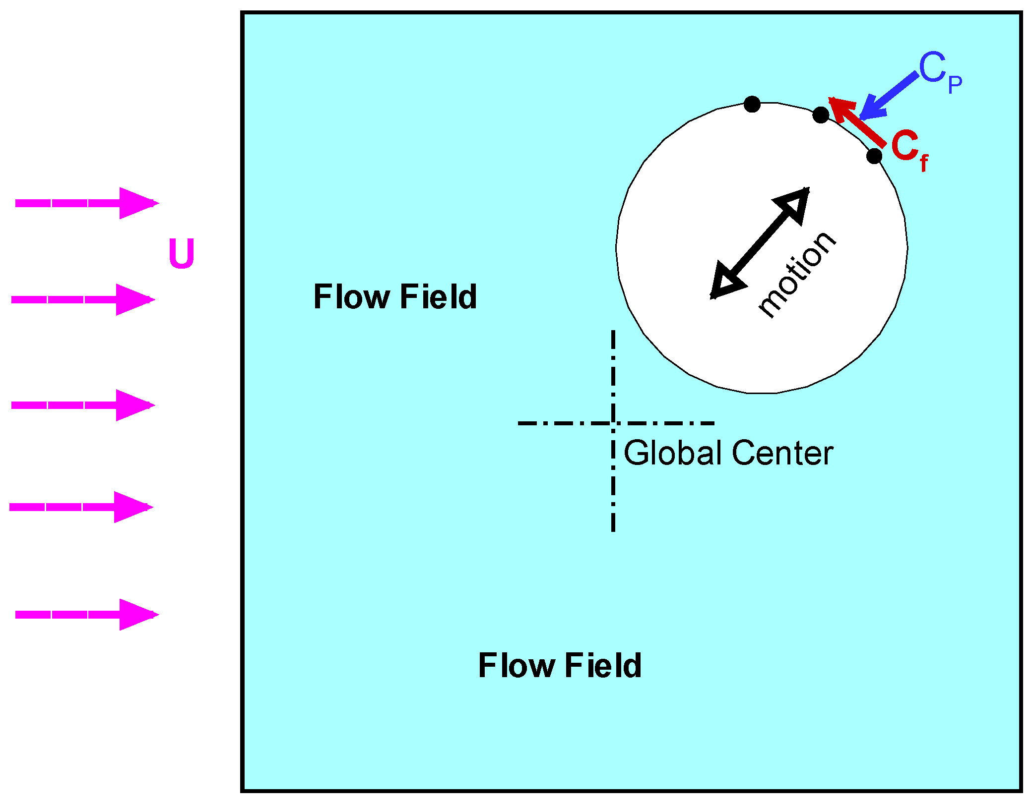
Figure 2.
Illustration of the pressure and friction coefficients at the cylinder surface.
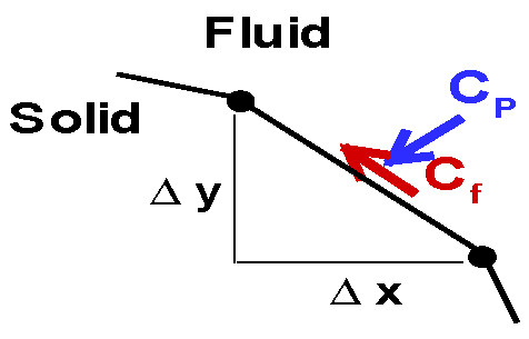
Figure 3.
Projection of the limit cycle onto the CL-η plane for a moving cylinder in the cross-stream direction. Results from our simulations (bottom) are compared with those from the simulations reported in [135] (top), reproduced with permission – License number 6026501366615 dated 12/May/2025, obtained through the CCC “Copyright Clearance Center” RighsLink® service).
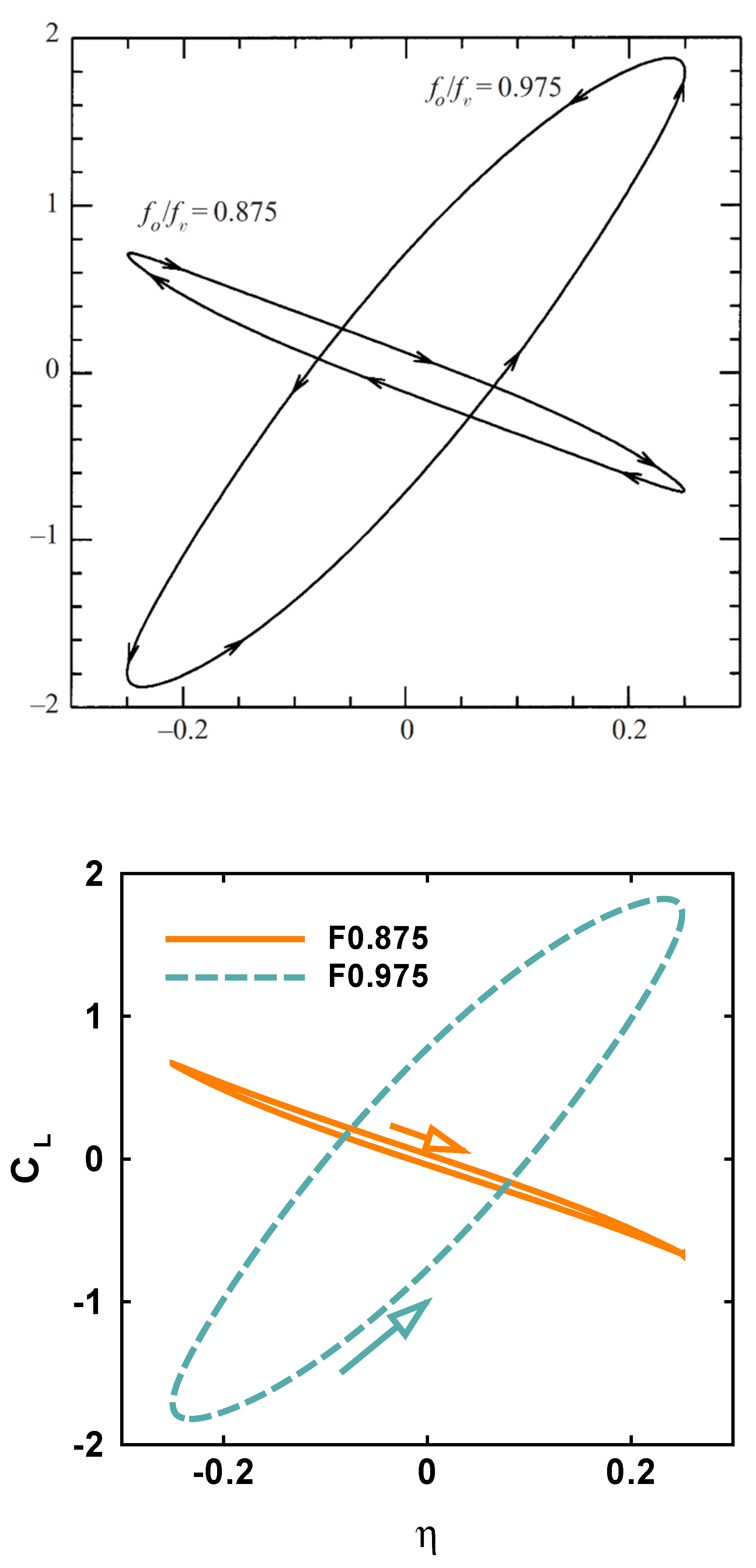
Figure 4.
Power spectra of the lift and drag for the fixed cylinder.
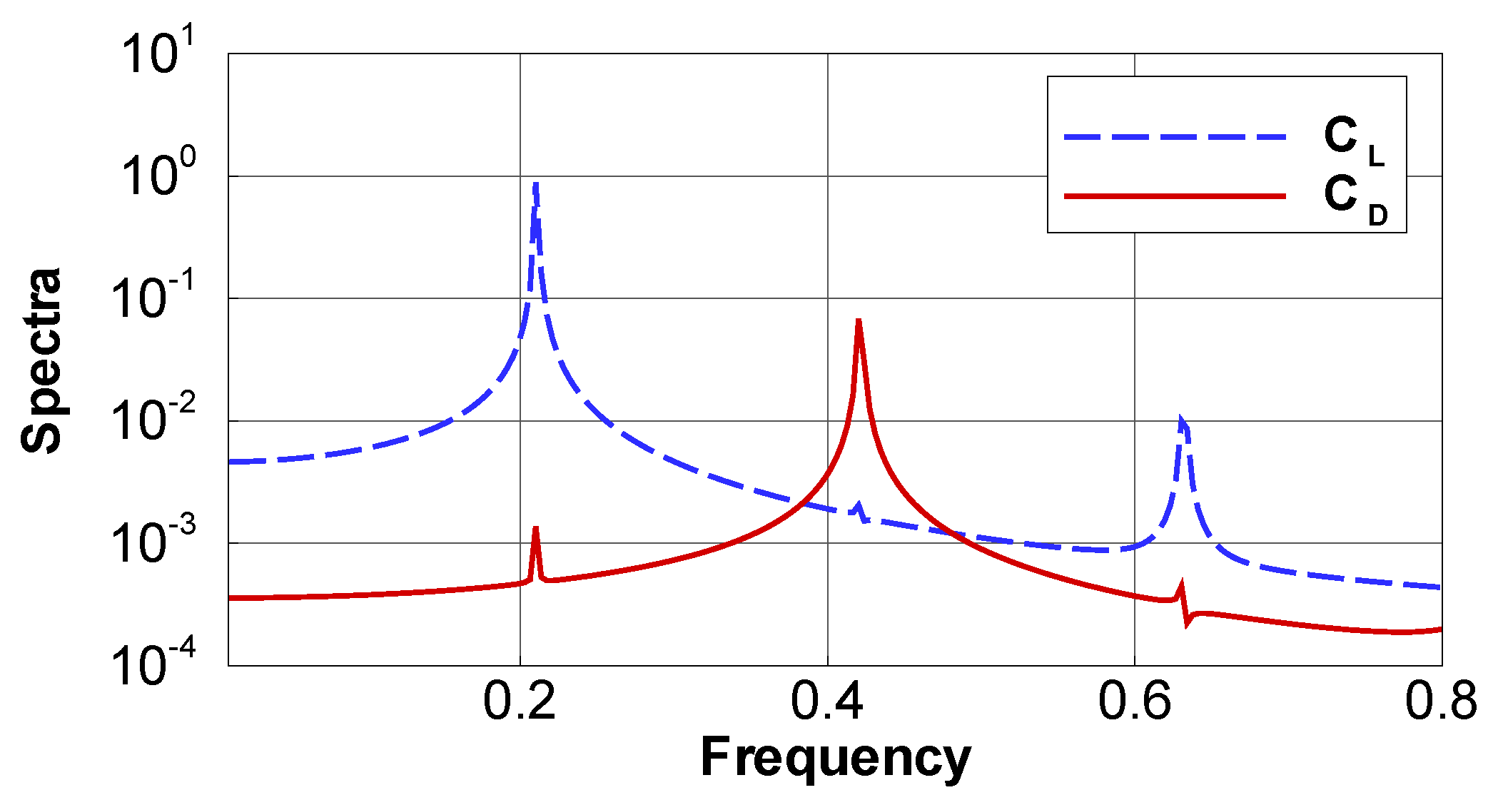
Figure 5.
Projection of the limit cycle onto the CL-CD plane for the fixed cylinder.
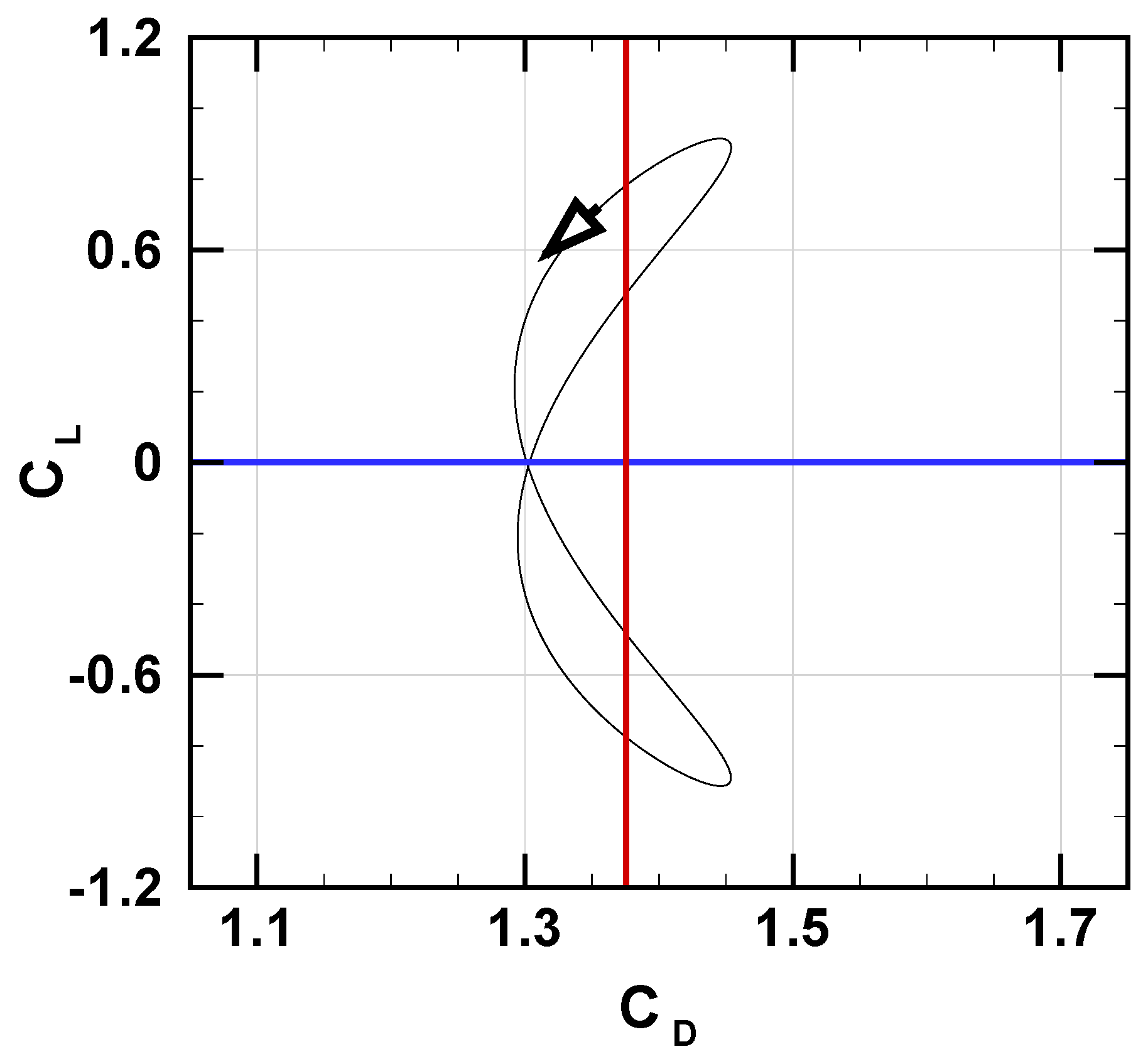
Figure 6.
Projection of the limit cycle onto the CL-CD plane for a moving cylinder compared at different cases with the motion axis is approaching the cross-stream direction. The motion is exactly along the cross-stream direction in case (f).
Figure 6.
Projection of the limit cycle onto the CL-CD plane for a moving cylinder compared at different cases with the motion axis is approaching the cross-stream direction. The motion is exactly along the cross-stream direction in case (f).
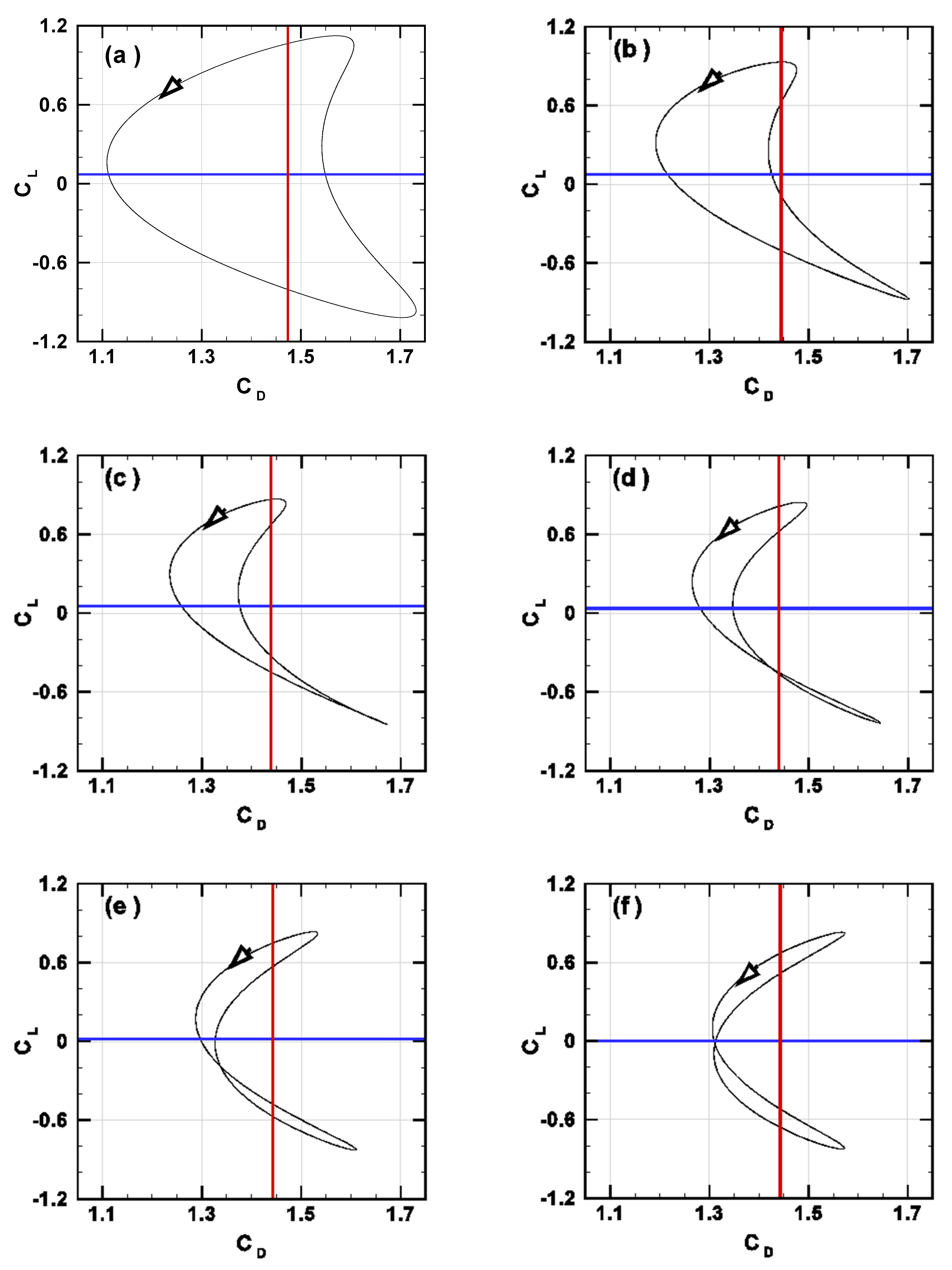
Figure 7.
Spectra of the lift and drag coefficients for the moving cylinder cases in Fig. 6.
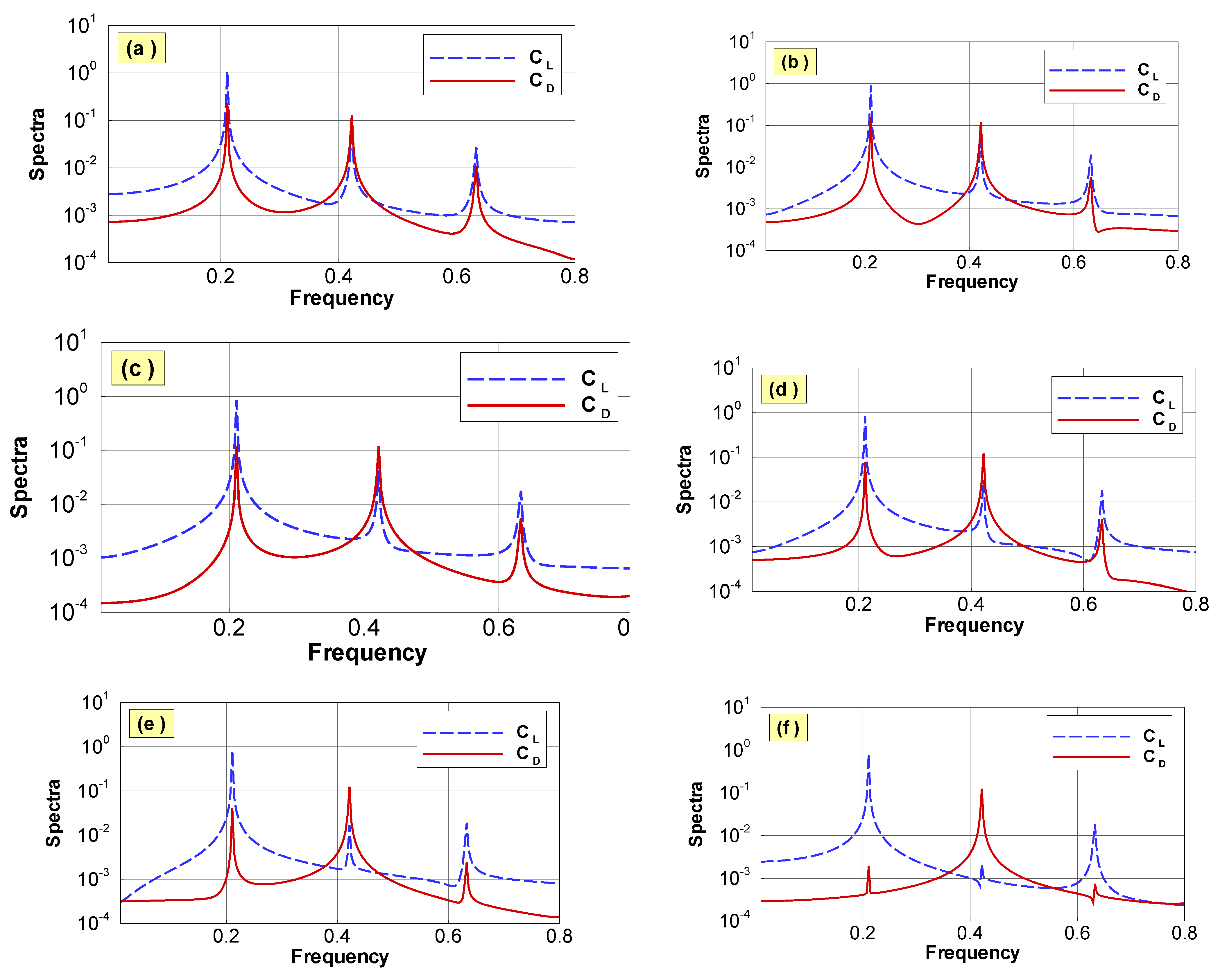
Figure 8.
Comparison of the modeled and simulated drag coefficient for the fixed cylinder. The simulated lift coefficient is also shown.
Figure 8.
Comparison of the modeled and simulated drag coefficient for the fixed cylinder. The simulated lift coefficient is also shown.
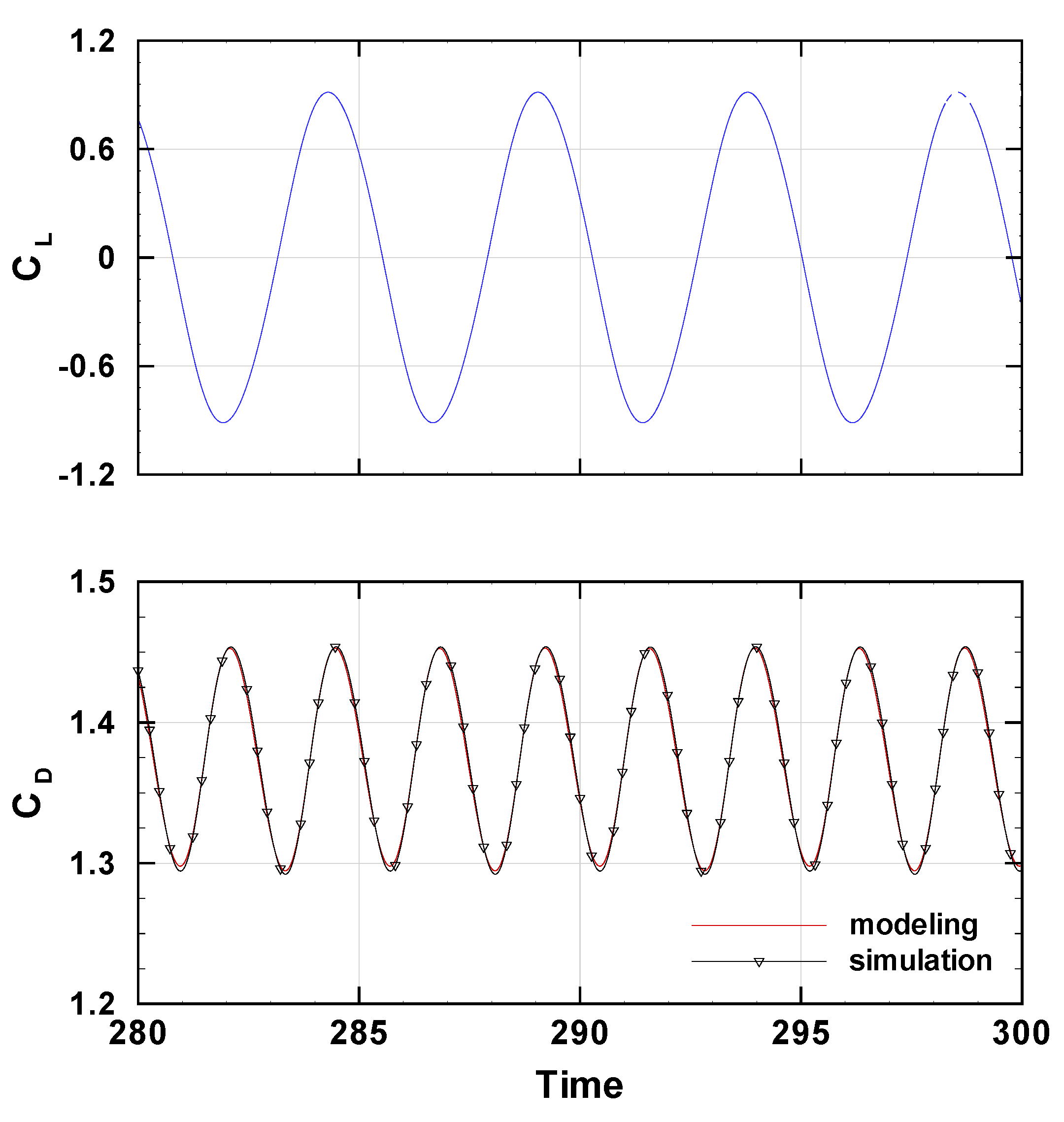
Figure 9.
Comparison of the analytical (significant harmonics) and numerical (simulation) representation of the lift coefficient for the fixed cylinder, and the corresponding modeled drag.
Figure 9.
Comparison of the analytical (significant harmonics) and numerical (simulation) representation of the lift coefficient for the fixed cylinder, and the corresponding modeled drag.
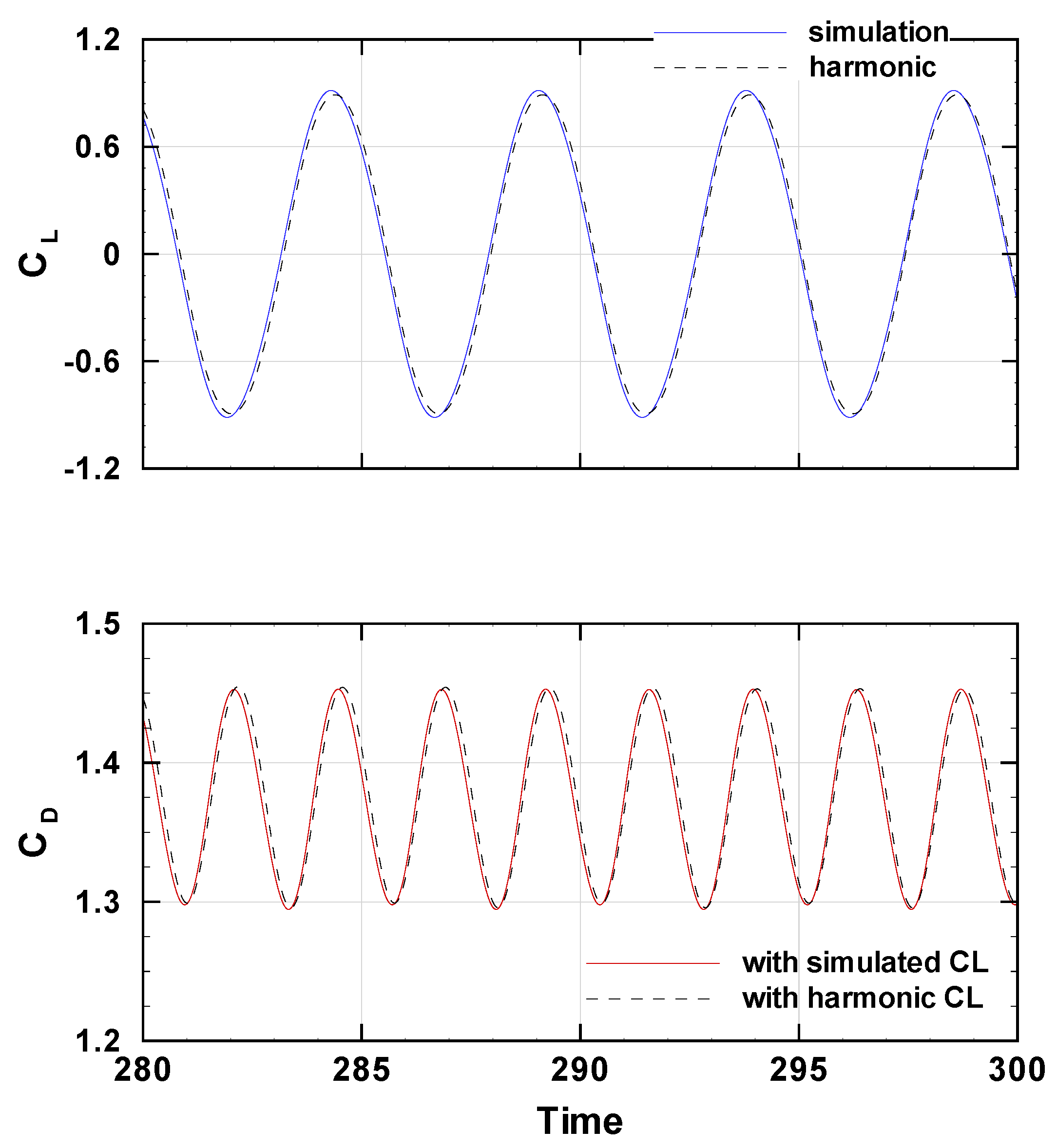
Figure 10.
Comparison of the modeled and simulated drag coefficient for a moving cylinder with a1D > a2D, with (middle) and without (bottom) linear coupling. The simulated lift coefficient is also shown (top). Simulation data correspond to case (b) in Figs. 6~7.
Figure 10.
Comparison of the modeled and simulated drag coefficient for a moving cylinder with a1D > a2D, with (middle) and without (bottom) linear coupling. The simulated lift coefficient is also shown (top). Simulation data correspond to case (b) in Figs. 6~7.
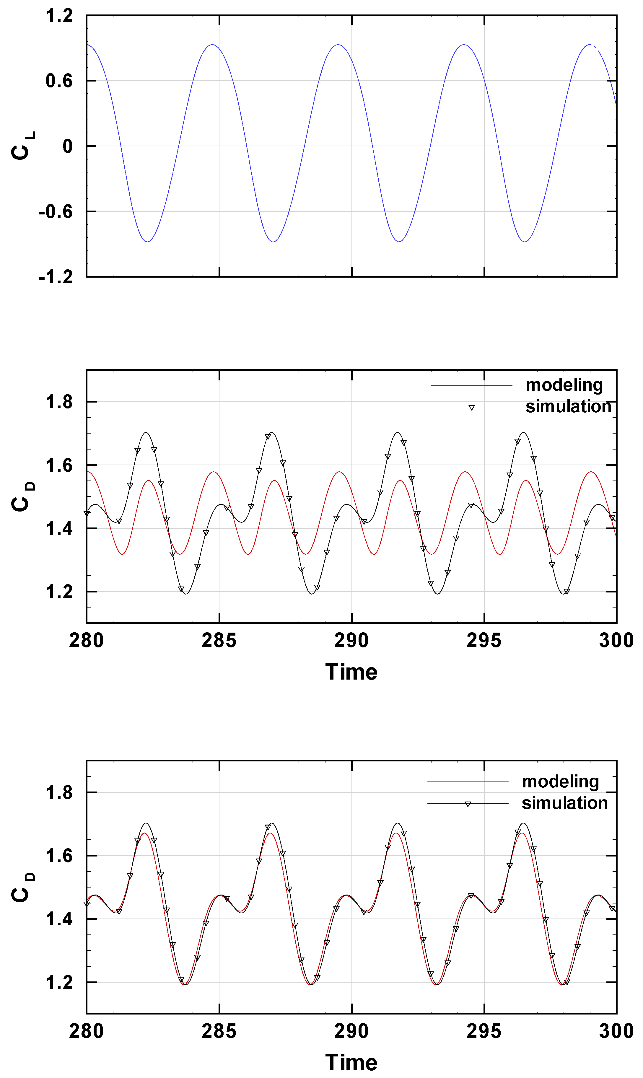
Figure 11.
Comparison of the modeled and simulated drag coefficient for moving cylinder with a1D < a2D, with (middle) and without (bottom) linear coupling. The simulated lift coefficient is also shown (top). Simulation data correspond to case (d) in Figs. 6~7.
Figure 11.
Comparison of the modeled and simulated drag coefficient for moving cylinder with a1D < a2D, with (middle) and without (bottom) linear coupling. The simulated lift coefficient is also shown (top). Simulation data correspond to case (d) in Figs. 6~7.
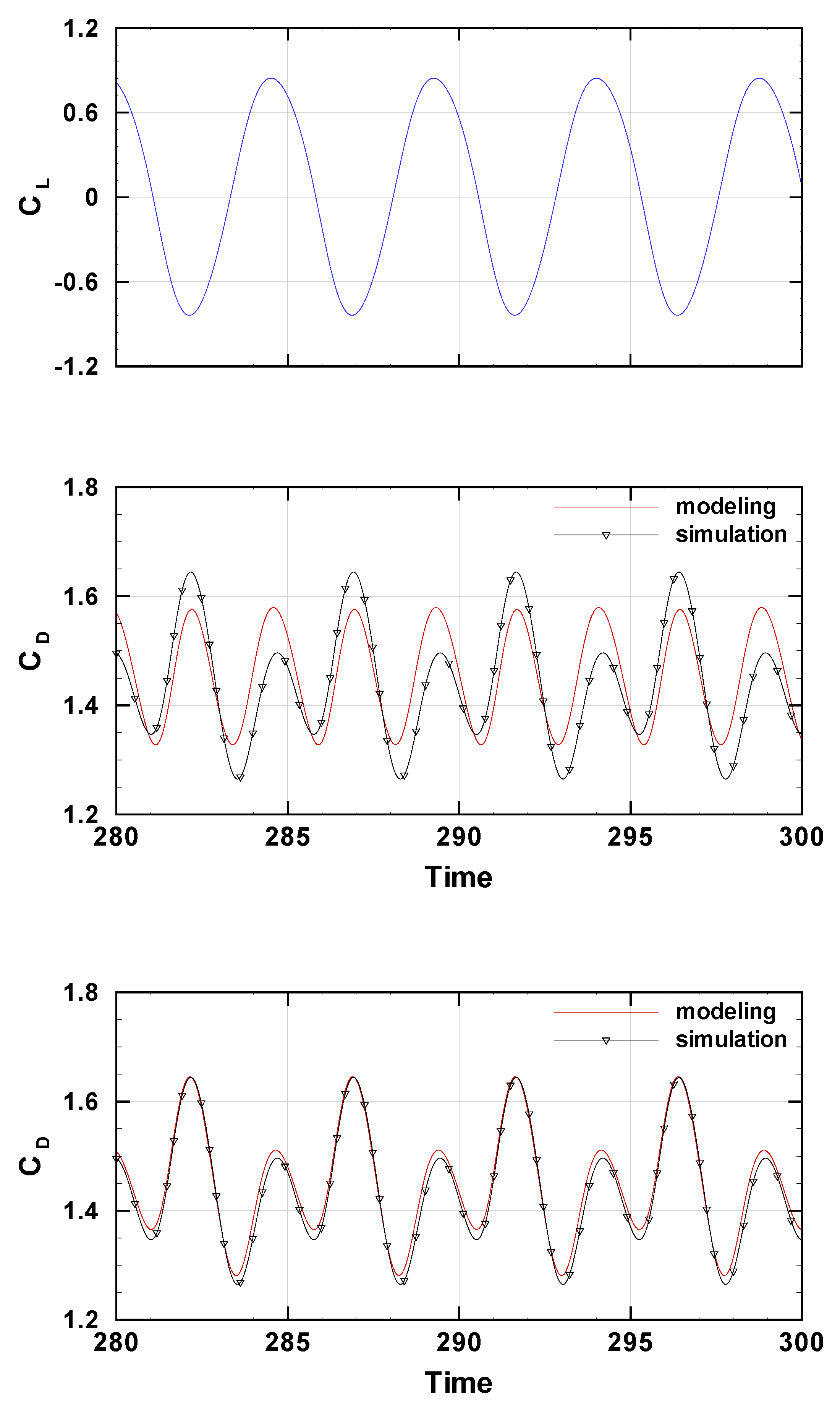
Figure 12.
Comparison of the modeled and simulated drag coefficient for a moving cylinder in the cross-stream direction, with (middle) and without (bottom) linear coupling. The simulated lift coefficient is also shown (top). Simulation data correspond to case (f) in Figs. 6~7.
Figure 12.
Comparison of the modeled and simulated drag coefficient for a moving cylinder in the cross-stream direction, with (middle) and without (bottom) linear coupling. The simulated lift coefficient is also shown (top). Simulation data correspond to case (f) in Figs. 6~7.
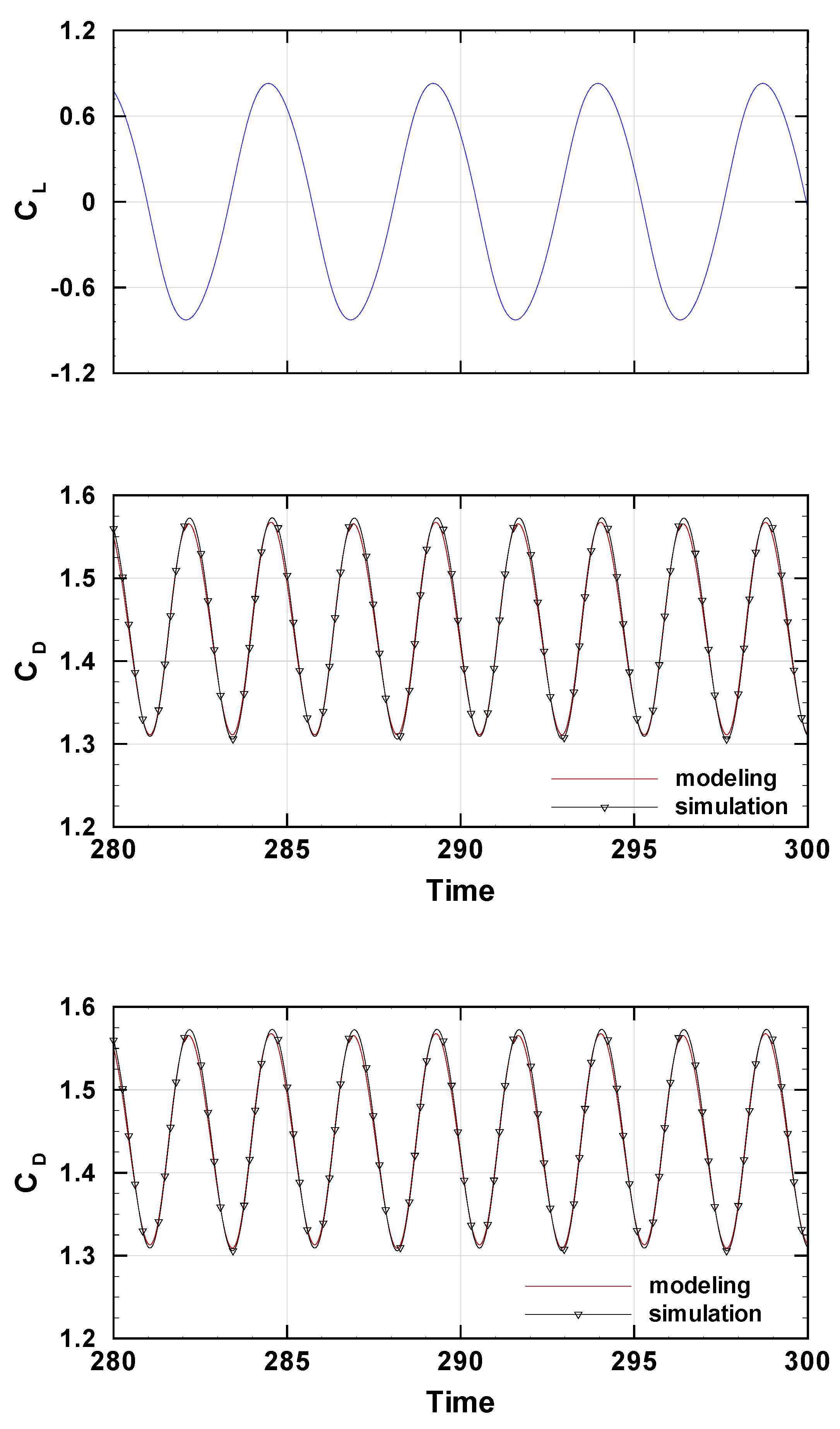
Disclaimer/Publisher’s Note: The statements, opinions and data contained in all publications are solely those of the individual author(s) and contributor(s) and not of MDPI and/or the editor(s). MDPI and/or the editor(s) disclaim responsibility for any injury to people or property resulting from any ideas, methods, instructions or products referred to in the content. |
© 2026 by the authors. Licensee MDPI, Basel, Switzerland. This article is an open access article distributed under the terms and conditions of the Creative Commons Attribution (CC BY) license (http://creativecommons.org/licenses/by/4.0/).
Copyright: This open access article is published under a Creative Commons CC BY 4.0 license, which permit the free download, distribution, and reuse, provided that the author and preprint are cited in any reuse.


