1. Specifications Table
| Hardware name |
Device for applying continuous positive or negative airway pressure for vocal training |
| Subject area |
Medicine |
| Hardware type |
Device for human biomedical rehabilitation |
| Closest commercial analog |
No commercial analog is available |
| Open source license |
GPL v3 |
| Cost of hardware |
The total cost of the material for the device building is ≈290€ (≈340 US$, as of December, 2025). |
| Source file repository |
https://data.mendeley.com/xxxxxxxxx |
2. Hardware in Context
Voice production is fundamental for human communication and social interaction, thus for psychological health. Phonation, the process of producing voice, is the result of a complex mechanical interaction between the upper airways, mainly the vocal folds, and the respiratory system (1). Indeed, the expiratory flow generated by action of the respiratory muscles induces high-frequency air vibrations (i.e. sound) when passing through the complex upper airway phonation structures (2). Voice generation and modulation depend on the geometry of the resonant cavity, on the passive mechanical properties of the soft phonation anatomic structures (e.g., stiffness, resistance, inertance), and on the active contribution of upper airway muscles involved in phonation (1,2).
Unfortunately, the capacity for adequate vocal expression in many patients is reduced or even made impossible because of inflammatory, tumoral or post-surgery alterations in the phonation components (3). Treatments for voice recovery include rehabilitation and training exercises. One of them consists of adding an impedance load to the vibrating elements in the airway during phonation, for instance by asking the patient to speak or sing while the vocal tract is semi-occluded (namely, by expiring through a straw-like tube) (4,5). This therapeutic approach is based on the hypothesis that adding an external mechanical load positively modifies the high-frequency dynamic interactions between the different anatomical elements involved in phonation hence improving voice recovery (6,7).
In this context, here we describe a novel device aimed at improving voice rehabilitation. It is based on applying either a positive or a negative constant airway pressure by means of a nasobuccal mask, starting at the end of inspiration (i.e. during expiration and thus phonation), and asking the patient to produce specific sounds (letters, words, sentences or songs) while subjected to such external airway pressures. The potential mechanisms involved in this approach for improving voice rehabilitation are: i) positive/negative airway pressure tends to dilate/constrict the soft-walled upper airway thus modifying their passive and active vibrational properties, and ii) positive/negative airway pressure hinders/facilitates the production of expiratory flow and thus phonation.
As the device presented herein is easy to build, low-cost, small and portable, it is potentially applicable for voice rehabilitation also at the patient’s home.
3. Hardware Description
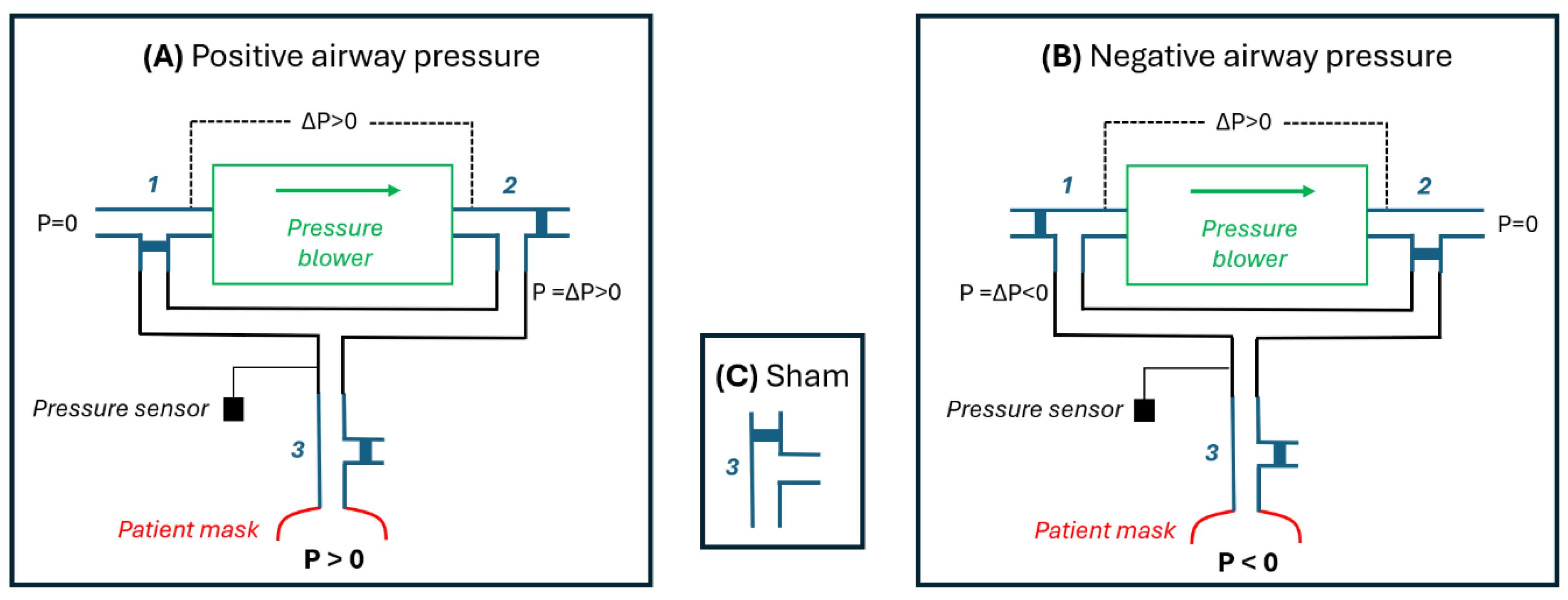
The device to apply controlled positive/negative pressure (P) to the patient’s mask uses a small, low-cost high-pressure blower (
Figure 1). The shape of the blades and their enclosure in this type of blower are designed to generate a considerable air pressure drop as the blades rotate against air viscosity. These blowers are commonly used as the autonomous pressure source in medical devices such as mechanical ventilators for patients with respiratory failure (8) and devices for applying continuous positive airway pressure in sleep apnea patients (9). The device presented herein is based on a blower, three 3-way ball electrovalves and an Arduino.
Figure 1A shows a diagram of the device with its electrovalves set to operate in positive pressure mode. The blower takes room air (P=0) and the pressure drop (∆P) induced by their blades rotation is applied as a positive pressure to the patient’s mask. This pressure is controlled and kept constant by a feedback loop that modulates the driving voltage applied to the blower according to the pressure signal measured by a transducer. The diagram in
Figure 1B shows how electrovalves 1 and 2 are set to induce negative pressure at the patient’s mask. In this case, the output of the blower is connected to room air (P=0) and thus the negative pressure from ∆P is connected to the patient’s mask.
For both the positive (
Figure 1A) and negative (
Figure 1B) modes, a sham pressure (P=0) can be applied to the patient’s mask by setting the electrovalve 3 as shown in
Figure 1C. In sham mode the patient’s mask is directly connected to room air (P=0) and isolated from the pressure generator which continues operating normally thus producing the same pressure as when actual pressure was applied to the patient. Hence, in sham mode the patient hears the same operation sound from the device as in the active mode but no pressure is applied to his/her airway.
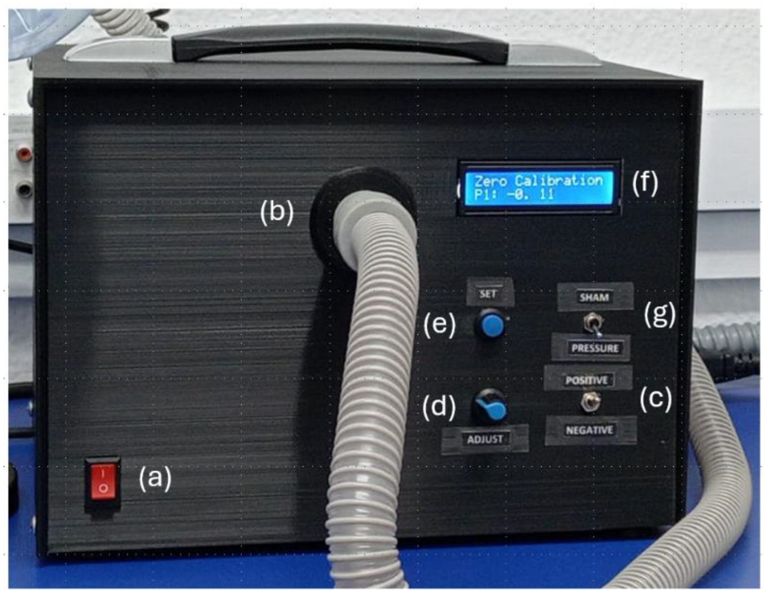
The assembled device is portable and very simple to operate by the user, either a healthcare professional or a patient using the device at home. Its use is straightforward since, in addition to a connector for the flexible tubing to the mask, the device front panel only contains the switches, button and a display for setting the desired pressure (
Figure 2).
4. Design Files Summary
All the design and software files necessary to build the device presented in this work are distributed under the GPL v3 license and they can be found in the
supplementary materials of this manuscript at the following public repositories (DOI:10.17632/8dnbrx3s6h.1XXXXXXXXXXX):
https://data.mendeley.com/datasets/g896nz5gm6/1)
Table 1.
Files summary.
| Design file name |
File type |
Open source license |
Location of the file |
| Enclosures and lids |
STL |
GPL v3 |
STL files folder |
| Code |
ino file |
GPL v3 |
Arduino Code folder |
| PCB Layout |
png and jpg file |
GPL v3 |
Electronics folder |
5. Bill of Materials Summary
The total cost of the materials for building the device is 291.12 €. Most electronic components, such as resistors, pin headers, and capacitors, were bought from a commercial assortment kit, although only a few pieces were required to assemble a single unit.
6. Build Instructions
6.1. 3D Design and Printing
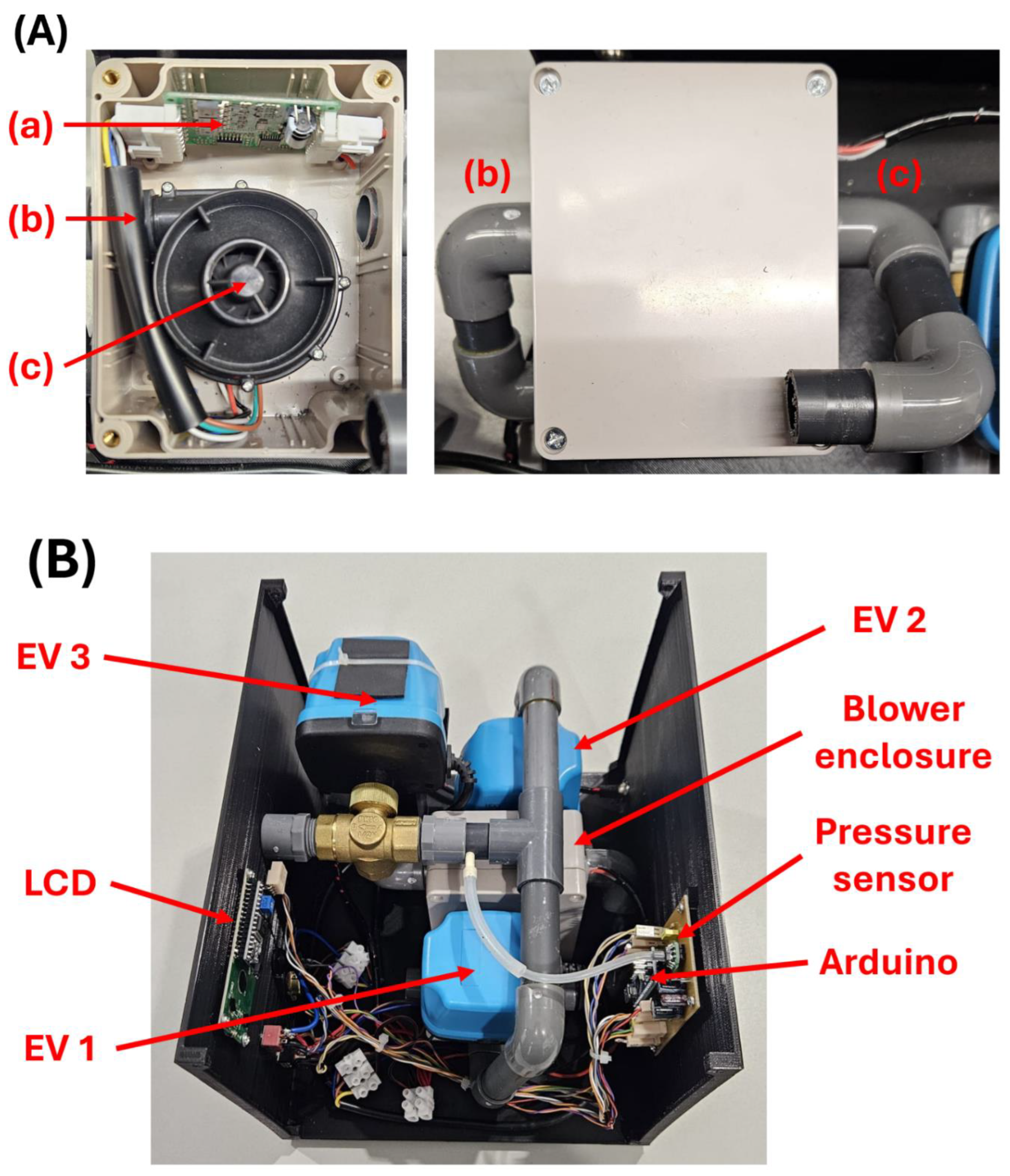
The blower we employed is originally designed to take room air from an open inlet and to expel it through a outlet tube. Therefore, positive pressure air is obtained directly from the outlet tube. To have a tube providing negative pressure, the blower was housed inside a sealed box open to the room air through an inlet tube, as shown in
Figure 3A.
Instead of solenoid electrovalves we chose 1/2” ball electrovalves (and 20 mm diameter tubing) since they present lower resistance to air flow (
Figure 3B), which is important to facilitate the expiratory flow during patient’s phonation. The fact that ball valves are slower than the solenoid ones is not a problem in this application where fast transitions are not required. Ball electrovalves tend to be heavier than solenoid valves, but this is of minor importance here since the weight of the whole device as currently implemented (
Figure 2) remains small (3.4 kg).
The complete device is housed inside a custom 3D-printed enclosure measuring 270 × 230 × 195 mm, designed in Autodesk Fusion 360. The enclosure is composed of two parts - a lower base and an upper top cover. All mechanical and electronic components, including the blower, valves, control electronics, and wiring, are mounted within this structure (
Figure 2 and
Figure 3B).
6.2. Electronics
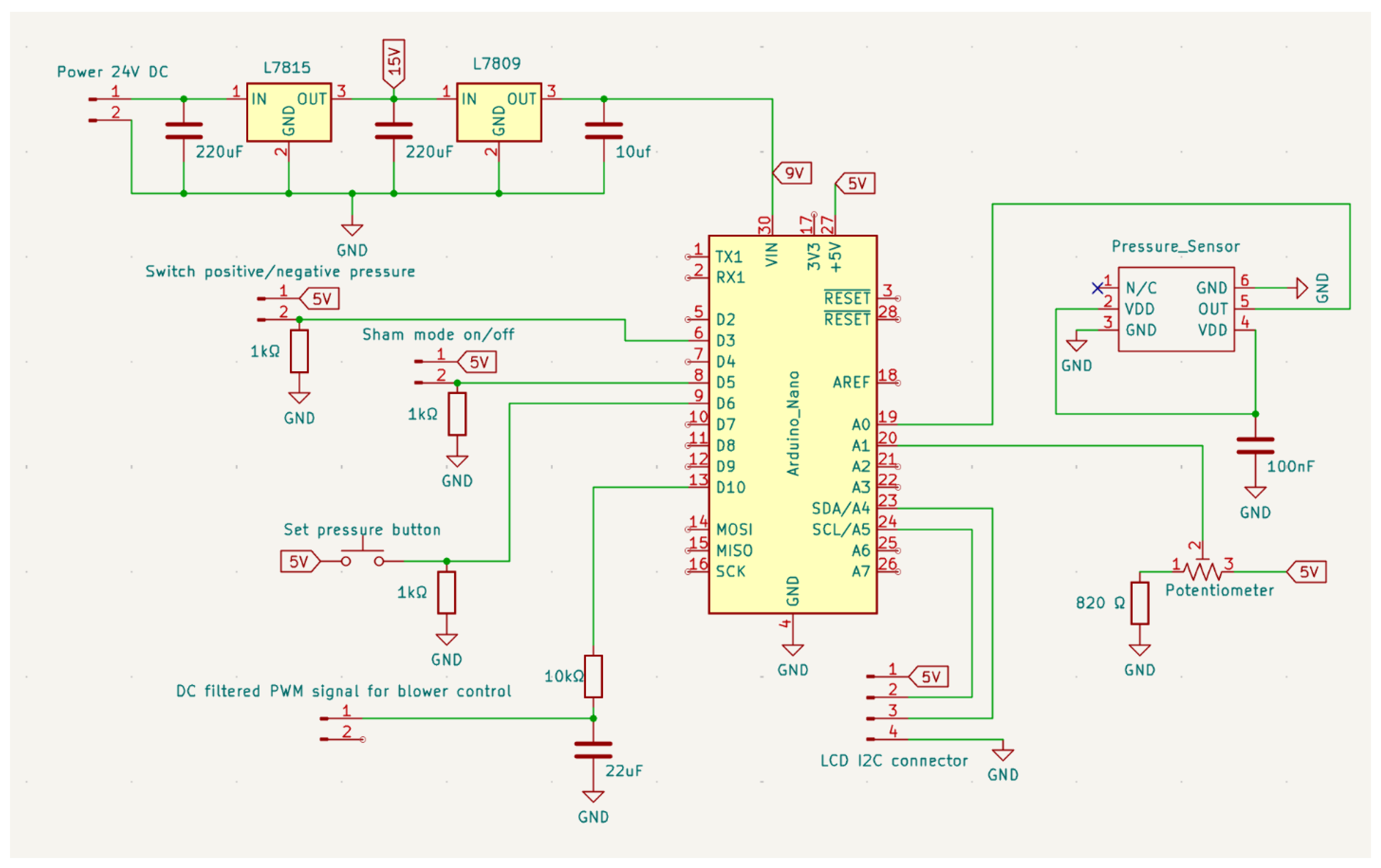
Figure 4 shows the complete electronic schematic of the control module designed to generate and regulate the external airway pressure delivered to the patient. The circuit integrates four main subsystems: power conditioning, digital control through a microcontroller, pressure sensing and regulation, and user-interface inputs and display.
The device is powered from an external 24 V DC supply, which is also used to power the 3-way electrovalves. The input rail is stepped down through voltage regulators in two stages, first to +15 V and then to +9 V, in order to distribute the power dissipation across the regulators and prevent thermal overload. Each regulation stage is stabilized using capacitors to ensure low-ripple and stable operation conditions.
The +9 V line is used to supply the Arduino Nano, which is the central processing unit of the system and coordinates all control operations.
A PWM signal generated by the microcontroller drives the blower, which requires a stable DC voltage. To achieve that, the PWM output is conditioned through a first-order RC low-pass filter, which filter removes the switching components of the PWM signal and extracts its DC component
The device incorporates two mechanical switches: one that controls the electrovalves setting thereby selecting between positive and negative pressure, and another that actuates the solenoid valve responsible for enabling the sham mode (
Figure 1). These switches operate at the hardware level by re-routing the electrical lines of the electrovalves and the sham valve. At the same time, two dedicated outputs from the switches are read by the Arduino, allowing the microcontroller to determine their positions and identify the current operating mode.
To adjust the target pressure, the user must keep a dedicated push button pressed while manipulating the front-panel potentiometer, whose analog output defines the desired airway pressure, corresponding to blower speed. This requirement prevents accidental changes during operation. When the push button is released, the set value is latched by the microcontroller and stored as the new pressure set-point for the closed-loop control system.
Airway pressure is measured using an analog pressure transducer (XGZP6847A), which provides a ratiometric voltage output proportional to the applied pressure and can be directly sampled by the microcontroller’s ADC, powered from the Arduino’s +5 V supply and electrically decoupled by a 100 µF capacitor. The resulting pressure signal feeds the control loop, which modulates the blower output to maintain the desired pressure by continuously adjusting the motor drive voltage.
A 4-pin I²C connector provides the communication interface to an external LCD module, which displays either the programmed pressure or the actual measured pressure, depending on the state of the front-panel push button.
6.3. Arduino Control
The firmware implemented on the Arduino Nano manages all real-time control and monitoring functions of the device. It is structured around four core tasks: sensor calibration, pressure acquisition, closed-loop blower speed control, and management of the operating modes and user interface.
Upon startup, the system performs an automatic calibration routine to determine the pressure transducer’s zero offset. The firmware acquires 91 consecutive measurements from the analog pressure input and computes their average, which is stored as the baseline reference. A second validation step follows, during which 50 additional measurements are taken; the system confirms that the corrected pressure remains below 0.3 cmH₂O. If this criterion is not met, the calibration is repeated.
During operation, the firmware continuously samples the analog pressure signal at high frequency. Readings are accumulated and averaged over a fixed window (20 ms). After baseline correction, the resulting value is converted into cmH₂O using the transducer’s calibration factor.
The desired pressure is achieved by a PI controller, implemented using the standard Arduino PID library. At each control cycle, the measured pressure serves as the input variable, while the desired pressure set-point is provided to the controller. The PI output modulates the PWM drive signal applied to the blower.
As previously mentioned, the pressure set-point is defined through a front-panel potentiometer but is only sampled when the user maintains the push button pressed. This mechanism prevents accidental changes during use. While the button is held, the firmware monitors the potentiometer value, converts it into the corresponding pressure in cmH₂O, and displays it on the LCD. After the release of the button, the current value is latched and used as the new target pressure for the PI controller.
Based on the switching architecture described in the previous section, the firmware continuously monitors the corresponding digital lines to identify the current configuration. According to the detected state, it updates the LCD with the appropriate mode indicator (e.g., “POSITIVE”, “NEGATIVE”, or “SHAM”) and manages the transition of the electrovalves by introducing a brief settling delay to ensure proper mechanical positioning.
A 16×2 I²C LCD provides real-time information to the user. During calibration, it displays progress and error states; during operation, it shows both the mode and the instantaneous pressure. To minimize processing overhead, the firmware updates static LCD fields only when the operating mode changes.
The main loop interleaves pressure acquisition, PI computation, switch monitoring, and LCD updates. After each control cycle, accumulator variables are reset to prepare the next sampling window. Time synchronization is achieved through a microsecond-resolution timer, ensuring deterministic control execution.
7. Operation Instructions
After the power is switched on and the sham switch is in the off position, the device is ready to apply airway pressure. At any time, the user can select positive or negative pressure by the corresponding switch. The value of target pressure (ranging from 0 to ±50 cmH
2O) can be set at any moment. To this end, the user should press the set button and while keeping it pushed, he/she can modify the setting potentiometer until the desired pressure value is seen in the display. At any time (with no interruption of pressure application), the user can check the value of the set pressure in the display by just pushing the setting button. In case the user wants to change from positive to negative pressure or vice versa, he/she simply must shift the mode switch. The change in mode will be effective after ≈6 s which is the time required to modify the electrovalves position (
Figure 1). The pressure value will remain the same (either positive or negative) until it is reset. Note that the airway pressure is effectively applied only in case the mask is well-fitted to the patient.
During both positive and negative pressure modes, the user can activate the sham mode by the corresponding switch. The only change will be that the electrovalve closer to the mask (3 in
Figure 1) will connect the mask directly to room air thus applying zero pressure at the airway. But the rest of the device will operate with no other changes. Hence, the blower will continue to generate the pressure currently set.
For any device setting, the patient maneuver should be the same. At the end of an inspiration, he/she must place the mask on his/her face trying to avoid air leaks and then initiate a mild expiration while producing the sounds (letters, words, sentences or songs) indicated by the phoniatrician either in person or by written instructions (home rehabilitation). Immediately after finishing the voicing, and before starting the next inspiration, the patient should retire the mask from his/her face and breathe normally until the next exercise with the mask is performed.
At the beginning of the first rehabilitation session with the positive/negative airway pressure, the patient must be informed that at the start of the expiration and phonation exercise wearing the mask he/she will experience an external pressure tending to modify his/her lung volume. Thus, the patient should be asked to activate his/her respiratory muscles to counteract the experienced external pressure, trying to maintain the initial lung volume (10). Specifically, when subjected to a (positive) pressure tending to increase lung volume, he/she must activate the expiratory muscles. On the contrary, when experiencing a (negative) pressure tending to reduce lung volume, he/she must activate the inspiratory muscles. Counteracting the external pressures applied by the device should not be a problem for the patient taking into account that the normal maximum inspiratory and expiratory pressures that can be produced by respiratory muscles (Müller and Valsalva maneuvers, respectively) are considerably higher than ±50 cmH2O (11,12). In fact, application of such positive and negative airway pressure values is clinical routine in conventional cough-assisting devices (13,14). It is recommended to perform some initial adaptation and training maneuvers with increasing positive and negative pressure values to familiarize the patient with the operation of the device.
8. Validation and Characterization
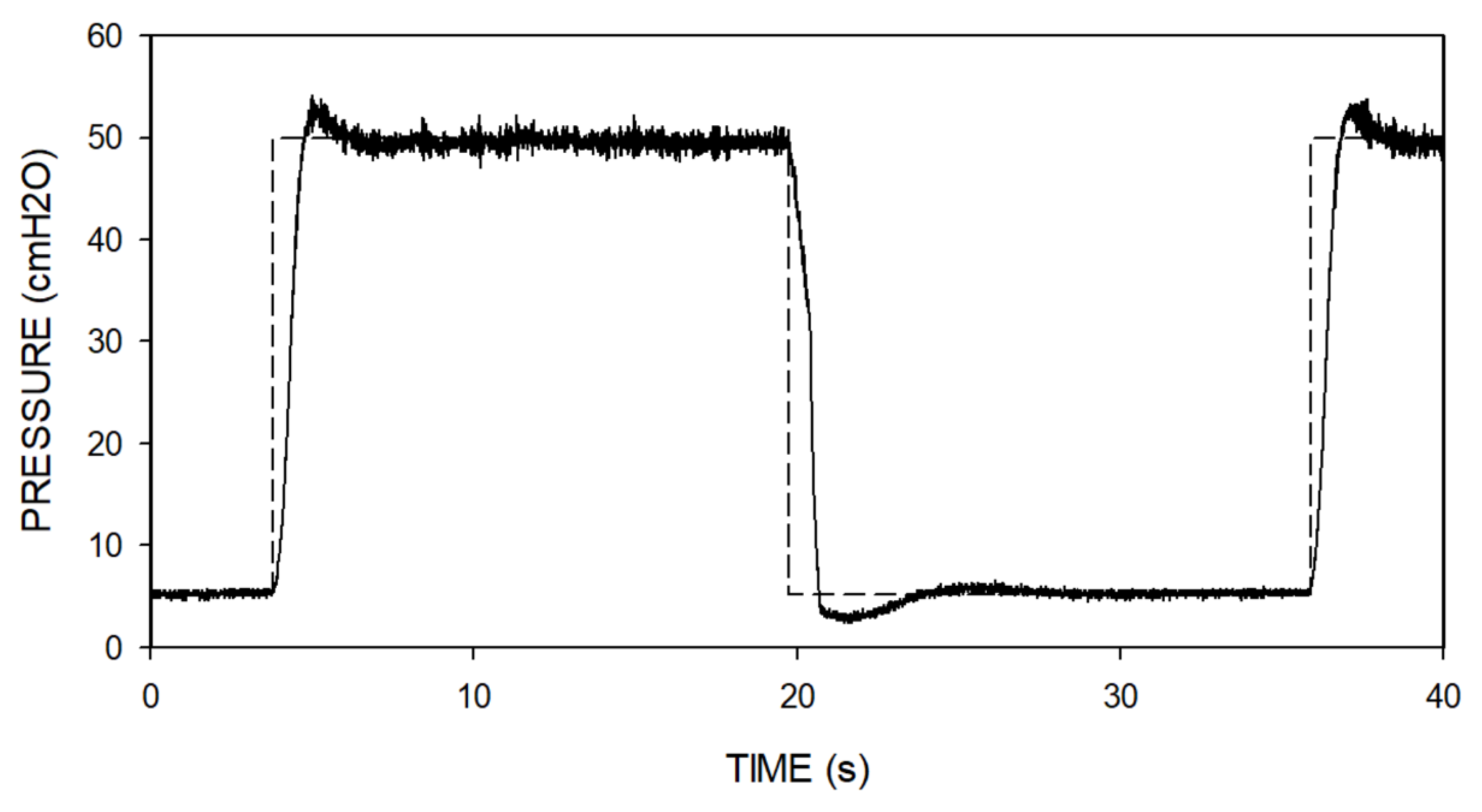
Two device validation tests were performed on the bench. First, we checked the adequacy of the blower control loop.
Figure 5 shows the response of the device when subjected to two steps in the control setting: from 5 to 50 cmH
2O and vice versa. The increasing pressure step, requiring active rise in the blower speed, exhibited a mild and short initial overshoot and a stabilized steady-state response. The decreasing pressure step was similar; the small differences observed were due to the fact that pressure reduction should be achieved passively since the simple low-cost blower we employed has no reverse mode.
The second bench test was aimed at measuring the actual impedance presented by the device to patient’s breathing. This test was necessary since previous data on the resistance to breathing of the type of blower we employed were measured when it was not working (15), and it is expected that the non-linear airflow regime generating pressure inside the blower blades would increase its effective airway resistance. To perform the test, the mask was connected to a patient simulator (Pulmonary Waveform Generator System, MH Custom Design & Mfg. L.C., Midvale, Utah USA) generating a pattern of typical spontaneous breathing consisting of a sinusoidal airflow of ±0.5 l/s amplitude at a frequency of 12 breaths/min. The effective device resistance experienced by the simulated patient, which was computed from the peak-to-peak amplitudes of pressure and flow, was 5.8–7.3 cmH2O·s/l for mask pressures ranging from –50 to 50 cmH2O. Given that the device is to be used while the patient is producing the mild expiratory flow (<0.1 l/s) typically required to vocalize, the corresponding load to the patient’s respiratory muscles for phonation would be negligible (< 1 cmH2O).
The technical validations described herein correspond to the specific prototype we built. Using components different from (although similar to) the ones described here to replicate the device may require technical adjustments or adaptations, and therefore the final performance of the resulting device must be specifically assessed.
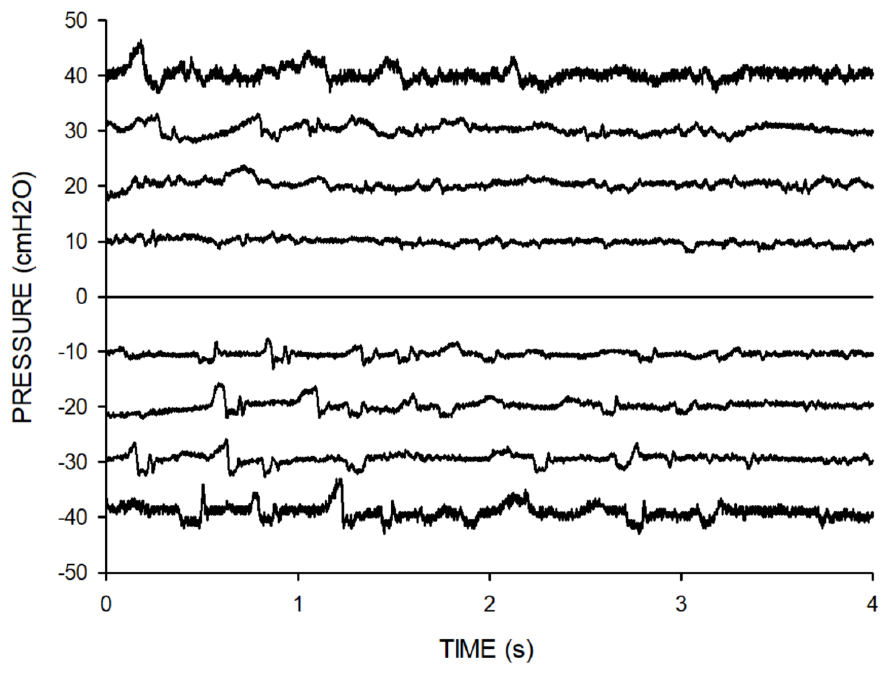
The real-life applicability of the device was preliminarily assessed in a phoniatrics center on 10 voluntary participants without vocal pathology. Each of them performed a 10-min session using the device alternating positive and negative pressures while producing isolated words and phrases as asked by the phoniatrician.
Figure 6 presents examples of the airway pressure recorded at the mask during the phonation maneuvers in one subject, showing that the device was able to apply constant positive and negative pressures while the patient vocalized. The variations observed around the applied constant pressures were caused by the patient’s phonation.
At the end of the session, the subjects stated that the maneuvers could be well performed. They also reported subjective improvement in perceived vocal comfort after the exercises with airway pressures. This feasibility test paves the way for further well-designed clinical studies aimed at assessing the therapeutic effectiveness of this simple and portable device for voice rehabilitation.
Supplementary Materials
The following supporting information can be downloaded at the website of this paper posted on Preprints.org.
Author Contributions
Raffaella Salama: Methodology, Validation, Writing; Miguel A. Rodríguez-Lázaro: Methodology, Validation; Maria Borragán-Salcines, Antonio Jimenez, Carles Exposito-Rovira, Isaac Almendros, Alfonso Borragán-Torre: Physiological and clinical conceptualization and testing; Ramon Farré: General conceptualization, Methodology, Validation, Writing-Reviewing, Editing, and Supervision; Jorge Otero: Technical conceptualization, Methodology, Writing-Reviewing.
References
- Herbst, C.T.; Elemans, C.P.H.; Tokuda, I.T.; Chatziioannou, V.; Švec, J.G. Dynamic System Coupling in Voice Production. J Voice 2025, 39, 304–316. [Google Scholar] [CrossRef] [PubMed]
- Zhang, Z. Mechanics of human voice production and control. J Acoust Soc Am. 2016, 140, 2614. [Google Scholar] [CrossRef] [PubMed]
- Neighbors, C.; Hashmi, M.F.; Song, S.A. Dysphonia. In StatPearls [Internet]; StatPearls Publishing: Treasure Island (FL), January 2025; Available online: https://www.ncbi.nlm.nih.gov/sites/books/NBK565881/?utm_source=chatgpt.com.
- Apfelbach, C.S.; Guzmán, M. Acoustic, Aerodynamic, Morphometric, and Perceptual Changes During and After Semi-Occluded Vocal Tract Exercise: An Integrative Review. J Voice 2024, 38, 404–425. [Google Scholar] [CrossRef] [PubMed]
- Fantini, M.; Succo, G.; Crosetti, E.; Torre, A.B.; Demo, R.; Fussi, F. Voice Quality After a Semi-Occluded Vocal Tract Exercise With a Ventilation Mask in Contemporary Commercial Singers: Acoustic Analysis and Self-Assessments. Journal of Voice 2017, 31, 336–341. [Google Scholar] [CrossRef] [PubMed]
- Tangney, J.; Scholp, A.; Kang, J.; Raj, H.; Jiang, J.J. Effects of Varying Lengths and Diameters During Straw Phonation on an Excised Canine Model. J Voice 2021, 35, 85–93. [Google Scholar] [CrossRef] [PubMed]
- Titze, I.R. Voice training and therapy with a semi-occluded vocal tract: rationale and scientific underpinnings. J Speech Lang Hear Res. 2006, 49, 448–59. [Google Scholar] [CrossRef] [PubMed]
- Garmendia, O.; Rodríguez-Lazaro, M.A.; Otero, J.; Phan, P.; Stoyanova, A.; Dinh-Xuan, A.T.; Gozal, D.; Navajas, D.; Montserrat, J.M.; Farré, R. Low-cost, easy-to-build noninvasive pressure support ventilator for under-resourced regions: open source hardware description, performance and feasibility testing. Eur Respir J. 2020, 55, 2000846. [Google Scholar] [CrossRef] [PubMed]
- Farré, R.; Montserrat, J.M.; Solana, G.; Gozal, D.; Navajas, D. Easy-to-build and affordable continuous positive airway pressure CPAP device for adult patients in low-income countries. Eur Respir J. 2019, 53, 1802290. [Google Scholar] [CrossRef] [PubMed]
- Farré, R.; Navajas, D. Ventilation Mechanics. Semin Respir Crit Care Med. 2023, 44, 511–525. [Google Scholar] [CrossRef] [PubMed]
- Laveneziana, P.; Albuquerque, A.; Aliverti, A.; Babb, T.; Barreiro, E.; Dres, M.; et al. ERS statement on respiratory muscle testing at rest and during exercise. Eur. Respir. J. 2019, 53, 1801214. [Google Scholar] [CrossRef] [PubMed]
- Aymerich, C.; Rodríguez-Lázaro, M.; Solana, G.; Farré, R.; Otero, J. Low-Cost Open-Source Device to Measure Maximal Inspiratory and Expiratory Pressures. Front Physiol. 2021, 12, 719372. [Google Scholar] [CrossRef] [PubMed]
- Chatwin, M.; Simonds, A.K. Long-Term Mechanical Insufflation-Exsufflation Cough Assistance in Neuromuscular Disease: Patterns of Use and Lessons for Application. Respir Care 2020, 65, 135–143. [Google Scholar] [CrossRef] [PubMed]
- Chatwin, M.; Wakeman, R.H. Mechanical Insufflation-Exsufflation: Considerations for Improving Clinical Practice. J Clin Med. 2023, 12, 2626. [Google Scholar] [CrossRef] [PubMed]
- Farré, R.; Montserrat, J.M.; Ballester, E.; Navajas, D. Potential rebreathing after continuous positive airway pressure failure during sleep. Chest 2002, 121, 196–200. [Google Scholar] [CrossRef] [PubMed]
|
Disclaimer/Publisher’s Note: The statements, opinions and data contained in all publications are solely those of the individual author(s) and contributor(s) and not of MDPI and/or the editor(s). MDPI and/or the editor(s) disclaim responsibility for any injury to people or property resulting from any ideas, methods, instructions or products referred to in the content. |
© 2025 by the authors. Licensee MDPI, Basel, Switzerland. This article is an open access article distributed under the terms and conditions of the Creative Commons Attribution (CC BY) license (http://creativecommons.org/licenses/by/4.0/).