Submitted:
19 November 2025
Posted:
21 November 2025
You are already at the latest version
Abstract
Piezoelectric sensors convert electric charge in response to mechanical loading and are widely studied for their high sensitivity. In particular, ferroelectret sensors provide the flexibility and material system design that enable biocompatibility. Insole-based gait and pressure sensing remain active research topics, yet most published electronics are limited to conceptual diagrams without practical strategies for noise mitigation or robustness against electromagnetic interference (EMI). Therefore, this work presents a compact, four-channel portable measurement system specifically designed for charge-based force sensing with piezoelectric sensors, called ChrisBox. A comprehensive shielding strategy, including both the circuit board and the sensor connection, via cost-effective USB Type-C cables is implemented. Performance was validated by comparing the output of the developed electronics with a calibrated electrometer under defined mechanical loads applied to a shielded ferroelectret sensor. The system measured the charge with a relative deviation of 8.2%, partly attributed to variability in the verification setup, with a high linearity of R2 > 0.99. In controlled EMI testing within a transverse electromagnetic (TEM) cell, noise levels remained below 0.1 pC RMS, enabling a signal-to-noise ratio (SNR) of 53 dB for a measured charge of 43 pC RMS during human pulse measurement with a ferroelectret. The results confirm the system’s suitability for portable, high-resolution ferroelectret sensing in EMI-prone environments and provide a foundation for further application-specific development.
Keywords:
charge amplifier
; electrometer
; ferroelectret sensor
; open-source hardware
; EMI shielding
; portable electronics
; sensor readout
1. Introduction
Piezoelectric sensors convert mechanical deformation into electrical charge, enabling the detection of forces, vibrations, and pressure with high sensitivity [1,2,3]. These sensors find application across various domains, from industrial monitoring to biomedical diagnostics, due to their passive operation and broad dynamic range [4,5]. The field has expanded with the rise of wearable and flexible sensing systems [6]. Among these, ferroelectret sensors, with the subclass of piezoelectric sensors, have gained increasing attention [7,8]. These sensors utilize a macroscopic piezoelectric effect by trapping charges inside their porous, air-filled structure and are promising for wearable force and motion tracking due to mechanical flexibility, low mass, and potential biocompatibility [9,10]. The possibility of 3D printing these sensors further enhances accessibility and customization for application-specific requirements [6,11,12].
Ferroelectrets have enabled numerous sensor designs with different form factors [13], in which the output charge has to be digitized. However, many reports provide only abstract circuit sketches of the charge readout electronics with limited implementation detail. Examples include flexible PVDF systems where the charge amplifier is shown only schematically [14] and stacked-PVDF devices that omit the specific op-amp or front-end design choices [15]. Insole-based gait and pressure sensing is an active topic of research, yet published electronics are often reduced to conceptual diagrams without concrete guidance on noise mitigation or shielding [16,17,18]. Similarly, recent P(VDF-TrFE) devices for physiological monitoring rely on custom-built charge amplifiers but lack sufficient details concerning implementation to ensure reproducibility [19].
A central challenge is the signal readout chain. At one end of the spectrum, high-precision laboratory instruments (e.g., Keithley 6517B, Keysight B2985A, Kistler 5015A) deliver excellent fidelity but are bulky and costly, limiting their suitability for embedded or wearable scenarios. At the other end, custom-built charge amplifiers target low-cost or portable deployments but frequently suffer from suboptimal signal-to-noise ratio (SNR), inadequate shielding, and poor robustness against electromagnetic interference (EMI). Compounding this problem, many custom-built front ends are not fully documented, hampering reproducibility and wider adoption.
Therefore, this work presents ChrisBox: an open-source, four-channel signal readout platform specifically designed for ferroelectret sensors and other charge-based sensors (Figure 1). ChrisBox, short for CHarge Reading Interface System BOX, combines compact hardware, EMI-optimized shielding, and USB-C sensor interfacing in a portable form factor, enabling field-ready deployment. The remainder of this paper details the design and implementation of ChrisBox (Section 2), provides build and usage instructions (Section 3 and 4), and reports on validation including EMI robustness (Section 5). Finally (Section 6), we present an example application and discuss implications for future sensing systems.
2. Design
This section presents the required fundamentals of piezoelectric sensors to then discuss the design rationale behind the development of ChrisBox.
2.1. Background of Piezoelectric Sensors
Piezoelectric sensors convert applied mechanical stress into electrical charge, and, in the small-signal regime, behave as high-impedance charge sources. The piezoelectric tensor quantifies the charge generated along the axis i per unit force applied in the direction j [20]. It is defined by the second partial derivative of the Gibbs free energy G regarding the electric field vector E and the stress tensor T over the temperature , i.e.,
Most commonly, the direct piezoelectric coefficients in the longitudinal direction and in the transverse direction are used, with units usually reported in [21]. For a parallel-plate structure uniformly stressed over electrode area A and thickness t, the resulting charge Q, capacitance C, and voltage V follow
In practice, this capacitance C is the sum of the sensor capacitance and all parasitic contributions of the cable and the front end. Therefore, long or lossy cables increase C, which decreases V, increasing susceptibility to interference when using simple voltage inputs. This is the central motivation for the usage of charge amplifiers, in which the signal path is designed to preserve charge information and to define a controlled transfer via a feedback capacitor [1,2].
A charge amplifier is a transimpedance stage typically built around an operational amplifier with a capacitive feedback element. Its core principle is to maintain the sensor input at (or near) virtual ground while integrating the input charge onto the feedback capacitor. This yields an output voltage directly proportional to the input charge
where is the feedback capacitance. An added benefit is that the effects of parasitic capacitances from cables and connectors are minimized, and the system becomes largely immune to cable length, leakage currents, and capacitive coupling. This makes charge amplifiers the preferred choice for piezoelectric signal conditioning.
2.2. Electronics System Design
The charge amplifier is central to the signal conditioning path in ChrisBox, as it preserves the information carried by the charge and converts it to a measurable voltage. While ultra-low-offset charge amplifiers have been demonstrated, for instance by Alnasser et al. [22], and are common in laboratory equipment, these approaches are optimized for low-frequency recordings and require more space on the printed circuit board (PCB) [23]. In contrast, ChrisBox targets portable measurement scenarios with motion and interaction signals predominantly in the low frequency range, where components below 1 Hz are of secondary concern [24].
Each of the four identically designed charge amplifier channels is based on a precision OPAMP (AD8605, Analog Devices, USA), selected for its ultra-low bias current (below 1 ), low input noise, and rail-to-rail input/output operation at a single supply. A four-channel configuration was deliberately chosen to balance versatility and complexity. On the one hand, many relevant applications in biomechanics and human-machine interaction involve multi-point measurements, such as capturing signals from several body locations simultaneously. On the other hand, limiting the design to four inputs keeps the system compact, cost-efficient, and easy to reproduce for teaching and research purposes. The amplifier is configured in a standard inverting transimpedance topology with a feedback capacitor , resulting in a gain of 2.78 mV/pC.
A large resistor is in parallel with , ensuring signal stability over time and preventing an integrator saturation. This introduces a high-pass behavior, with the lower cutoff frequency defined as
In order to allow full bipolar swing within a single-supply system, all amplifier inputs are biased to a mid-supply reference voltage , generated by a dedicated low-noise linear regulator (Figure 2). This ensures that the output signal oscillates around the midpoint of the analog supply (), maximizing dynamic range and compatibility with the subsequent analog-to-digital converters (ADC).
The analog output is digitized by a 24-bit delta-sigma ADC (ADS1220, Texas Instruments, USA), which supports sampling rates of up to 2 per channel and integrates both a low-drift reference and a programmable gain stage. Based on the previously calculated charge gain configuration, one bit of the ADC corresponds to
At a sampling rate of 1 kHz, the datasheet specifies an effective resolution of 16.74 noise-free bits (RMS) and 14.14 bits (peak-to-peak) when no additional gain is applied. This translates into an input-referred noise level of (RMS) and 0.065 pC (peak-to-peak) contributed solely by the ADC. All four input channels share common reference signals and are routed with matched impedances to minimize cross-talk.
Separate low-dropout regulators (LDOs) are used to supply , analog supply , and digital logic , ensuring a clean and isolated power domain compared to switching converters. An optional Li-ion battery powers the system, and a capacitive boost converter provides a stable 5 rail for powering peripheral components such as the display. A dual-core microcontroller (ESP32-S3-MINI-1, Espressif Systems, China) serves as the main processor, handling ADC communication, data processing, and wireless transmission (Wi-Fi or Bluetooth). Its low-power modes further enable standalone operation and real-time streaming to external devices or cloud platforms.
Signal integrity in the presence of long cables and low-level charges from the ferroelectret sensor is ensured through careful PCB layout and external wiring design, with a focus on shielding. The PCB is structured as a four-layer board, with most signal traces on the top layer. Two dedicated ground planes are used: one for low-impedance current return paths and one as a shielding layer. These, together with a metallic shielding cover, enclose the analog front end and minimize susceptibility to EMI. The microcontroller and digital lines are partially routed outside the shield, as digital signals are inherently more robust against external disturbances.
2.3. Cable Connection
Since the connection with the sensor must exit the shielding cover, care is taken to continue shielding beyond the PCB. For this purpose, a USB Type-C connector and cable are used. Among standard connector types, USB Type-C offers several advantages: it is cost-effective, compact, mechanically robust for repeated plug/unplug cycles, and widely available. In addition, USB Type-C cables are available in a broad range of lengths and mechanical flexibilities, including soft and lightweight variants that do not interfere with human motion during measurements. While coaxial and triaxial cables offer excellent shielding, they are less practical in wearable or mobile setups due to stiffness and form factor.
A USB 2.0-compliant Type-C cable is sufficient for signal transmission, as the analog signals require only the differential data lines D+ and D−. Other USB-specific lines, such as , , , and , remain unconnected. This ensures that if a standard USB device, such as a charger or computer, is mistakenly connected, no enumeration or power delivery occurs. Nevertheless, using a fully featured USB 3.0 or higher cable can further improve shielding effectiveness, since these cables typically contain additional ground lines and braided shielding layers, thereby enhancing resilience against EMI.
For continuity of the shielding concept, the cable shield is directly connected to the PCB shield via the connector. In addition to the sensor-side USB-C port, ChrisBox features a separate Micro-USB connector that serves two purposes: first, to establish a data connection to a PC for configuration and real-time monitoring, and second, to charge an optional internal battery during mobile operation.
2.4. Software
The software architecture of the ChrisBox system was developed in the Arduino IDE and is optimized for low-latency data acquisition, real-time visualization, and flexible communication with external devices. Communication with the ADCs is handled via a shared SPI bus, with separate chip-select and data-ready lines to enable asynchronous triggering and fast channel switching. The ADCs are initialized during the system setup and operate in single-shot mode with differential input between the sensor electrodes. During runtime, a continuous loop samples the four ADCs, converts raw data, and packages the results into a structured data block. The results are transmitted via a USB serial communication and optionally over wireless interfaces.
Three primary output interfaces are supported. First, standard serial output via USB allows real-time monitoring. Second, the ESP-NOW protocol enables wireless peer-to-peer communication with other ESP32-based devices without requiring a central access point. This is particularly useful in experimental or mobile setups where tethering is undesirable. Third, a UART interface connects the system to a touchscreen display (Nextion NX3224K024, iTead Studio, China). The display provides an intuitive interface for live monitoring of sensor signals, system voltage, and configuration pages.
3. Build Instructions
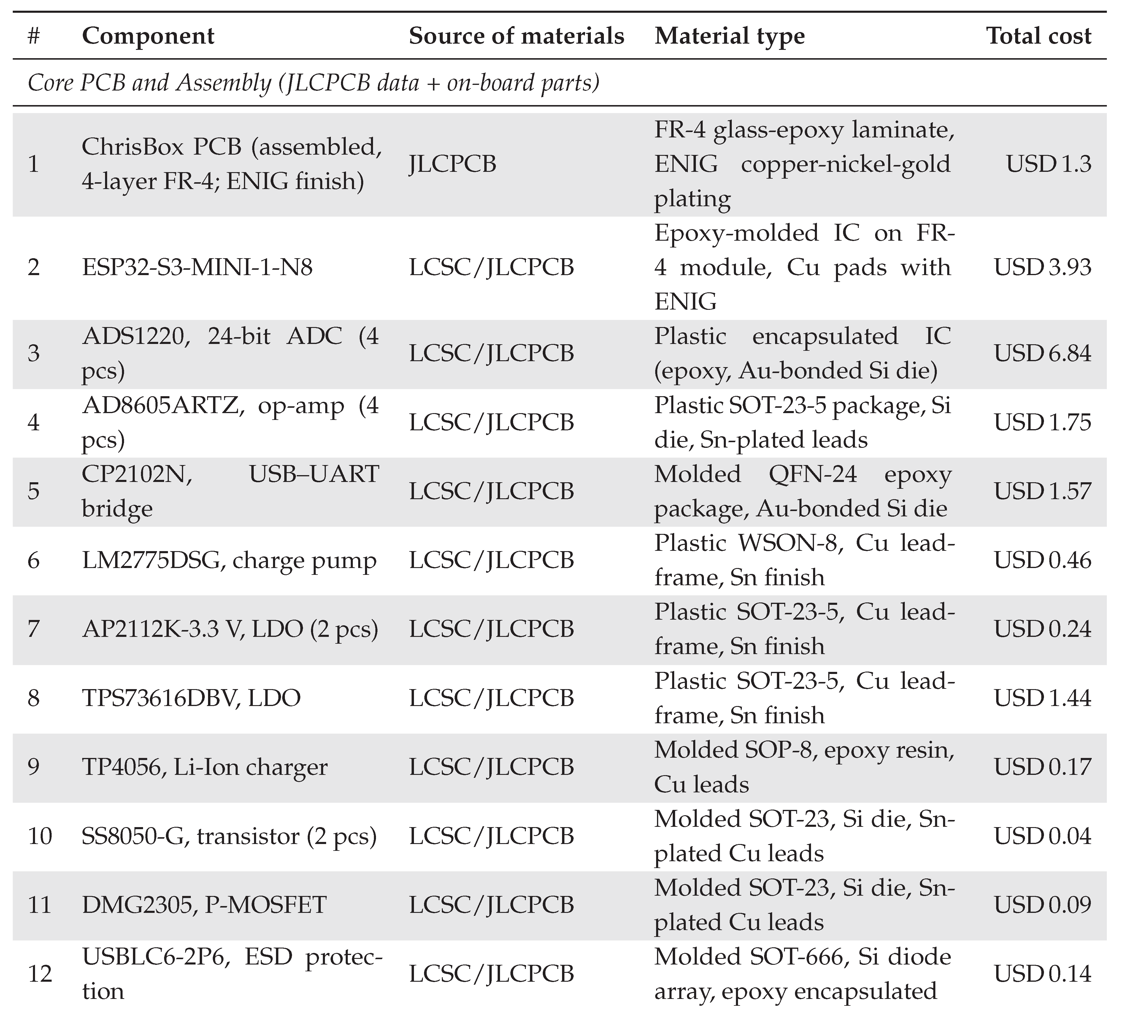
ChrisBox consists of a custom PCB, associated firmware, optional display hardware, and a 3D-printed casing (Figure 3). A detailed build manual, including bill of material, images, and wiring diagrams, is provided in the project repository. The total cost of one ChrisBox is ∼USD 70 (See Appendix A.).
The manual is organized into sections covering PCB hardware preparation, firmware installation, display programming, and mechanical assembly. Standard mechanical components and printed parts are referenced by their file names, and each is accompanied by an image for easy identification. Component lists are provided at the start of each section to ensure all required materials are available before assembly. The overall process, along with the approximate time required for each step, is outlined as follows:
-
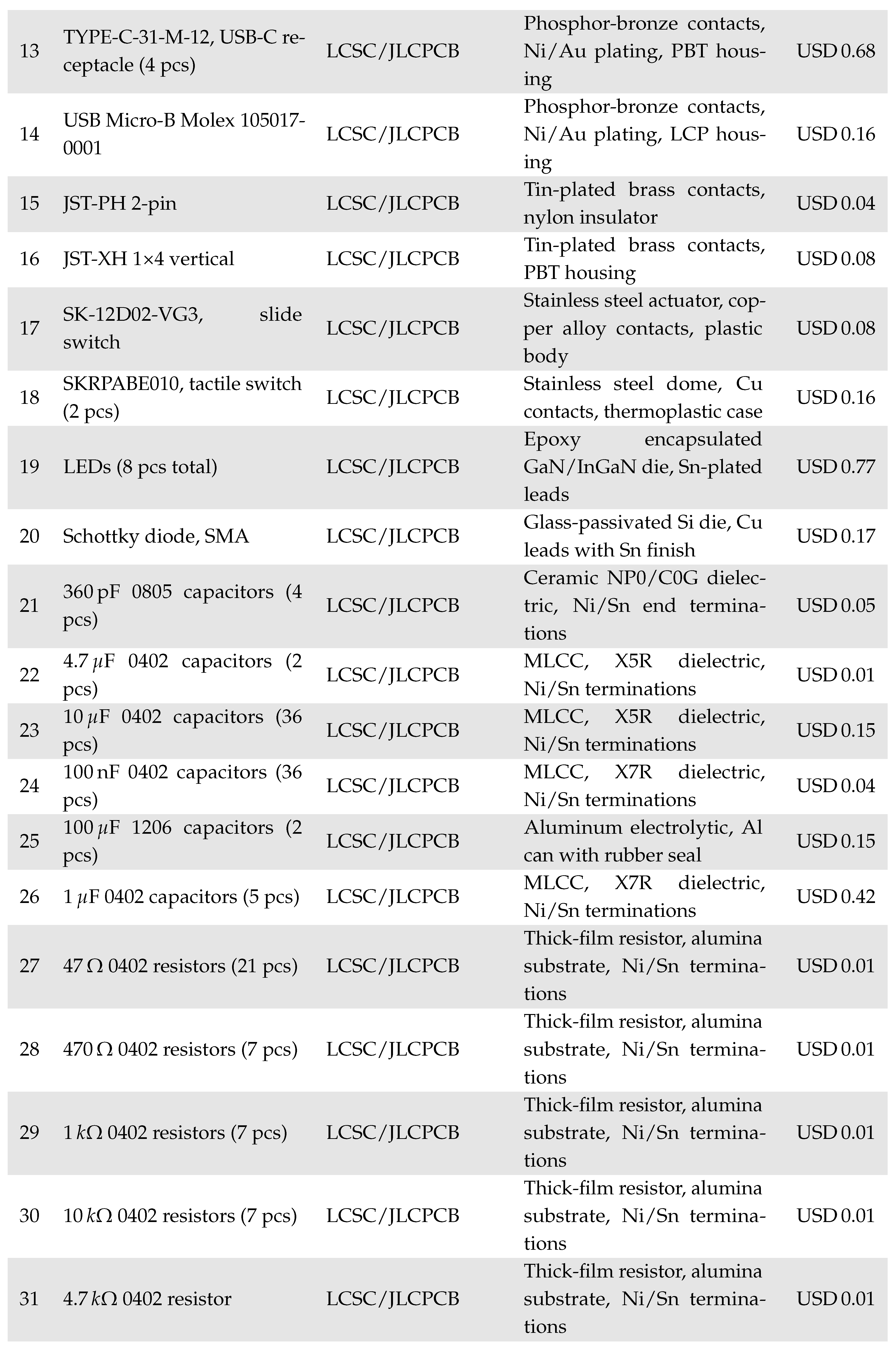
PCB hardware preparation (1 h): Order a preassembled PCB from a manufacturer (e.g., JLCPCB) using the provided production files. Due to manufacturing limitations, two components must be soldered manually after delivery: four 5 G feedback resistors (0805 package) and a shielding frame (BMI-S-205-F, Laird Technologies, USA). A matching shielding cover (BMI-S-205-C, Laird Technologies, USA) is placed afterward and does not require soldering.Tools required: Soldering iron, tweezers.
-
PCB software installation (10 min): The PCB contains a microcontroller (ESP32-S3-MINI-1, Espressif Systems, China) with a USB-to-UART bridge (CP2102N, Silicon Labs, USA). Install the Silicon Labs CP210x driver on the host computer, connect the PCB via Micro-USB, and power it on. In the Arduino IDE (tested with version 2.3.6), install the esp32 board package via the Boards Manager, select the correct device and COM port, and open the provided source code from the repository. Configure the upload options as specified in the documentation, then flash the firmware. Successful uploads are indicated by a blinking LED and serial data at 115200 baud, which can be monitored via the Arduino Serial Monitor or external tools such as MATLAB.Tools required: Computer, micro-USB cable.
-
Display Programming (5 min): The optional display (Nextion NX3224K024, iTead Studio, China) is programmed using the precompiled firmware. Copy the file to a blank microSD card, insert it into the display’s card slot, and power the display via 5 V and GND (either from the ChrisBox PCB or a USB adapter). The update starts automatically and completes within a minute. After powering off, remove the microSD card; the program on the display will start automatically when powered up.Tools required: microSD card, microSD card reader, 5 V power source.
-
Final mechanical assembly (2 h): 3D print the casing components (top, bottom, four spacers). Insert the threaded inserts using a soldering iron or heat press. Connect the Nextion display to the PCB using the supplied cable or a custom JST XH connector harness, ensuring correct pin mapping (GND–GND, 5 V–5 V, RX–TX, TX–RX). Place the display in the top casing half and the PCB in the bottom half with spacers and M3×25 screws. Join both halves and tighten all screws evenly.Tools required: 3D printer, soldering iron (for inserts), screwdriver.
For detailed images, part identifiers, and wiring diagrams, refer to the full assembly guide in the repository.
4. Operating Instructions
The ChrisBox system is designed to offer a plug-and-play interface for charge-based sensing applications. Once programmed, the system is powered either via USB or an external battery. When powered from a battery, the internal boost converter generates a stable 5 supply for peripherals such as the touchscreen display. Sensor connections are made using shielded USB Type-C cables. The measurement begins automatically after startup, and sensor signals are continuously sampled by the four ADCs. Data is then made available through three parallel output modes: standard USB serial communication for PC-based logging or visualization, UART output to the Nextion display for direct on-device feedback, and wireless data transmission via the ESP-NOW protocol. The selection and combination of outputs can be configured in the firmware.
Basic system status is communicated using onboard LEDs that indicate power availability, communication activity, and battery voltage warnings. If a Nextion display is connected, live sensor readings, system voltage, and signal quality indicators are shown in real-time. For applications that require mobile deployment or on-body use, ChrisBox can operate untethered and transmit data wirelessly.
5. Validation
We examine two primary aspects to confirm the ChrisBox system’s operation: the precision of charge measurement and the system’s resistance to EMI.
5.1. Accuracy Measurement
We employ a ferroelectret sensor that we previously discussed [6] for determining the accuracy. The sensor was fabricated by combining 3D-printed (MK3S+, Prusa Research a.s., Czech Republic) PLA spacers (PLA transparent filament, REDLINE FILAMENT GmbH, Germany) on a bulk PLA film (20 um, Yito Packaging Co. Ltd., Huizhou, China). The spacer structure was then sealed with a second PLA film to form air-filled cavities and subsequently metallized with a 100 nm thick aluminum layer on both sides using a physical vapor deposition unit (BAL-300, Balzers Ltd., Switzerland) to manufacture the electrodes. A shielding layer and soldered wire connections were then added, and the sensor was encapsulated in a silicone layer (EcoFlex 5, Smooth-On Inc., USA) to ensure mechanical robustness and electrical insulation. After fabrication, poling was performed by applying a 2 kV DC field across the sensor to polarize the air-polymer interfaces and trap quasi-static charge on the cavity surfaces. In order to ensure stable measurement conditions, the sensor was stored after polarization for six months prior to use, allowing the charge to stabilize. Consequently, charge stability can be considered sufficient for the comparative accuracy measurements reported in this work. The sensor was directly soldered to a USB Type-C plug and shielded with copper tape connected to the ground pad of the connector, thereby extending the global shielding concept to the ferroelectret sensor.
A mechanical testing machine (Inspekt solo 2.5 kN, Hegewald&Peschke, Germany) was used to apply controlled compressive loads to the sensor (Figure 4a). Loads were applied in five discrete steps from 25 mN to 125 mN, in 25 mN increments. For each load level, the force was released five times at a retraction speed of 5 mm/s. This release phase was used to determine the measurable charge, since approach dynamics can introduce variability due to differing high-pass behavior between systems. The resulting charge signals were recorded separately using both a commercial electrometer (Model 6517B, Keithley Instruments, USA) and the ChrisBox (Figure 4b).
Quantitative comparison was performed offline in MATLAB R2024b. For each load level, the charge output of the ChrisBox and the Keithley electrometer was averaged over five repetitions. The 95% confidence interval of the mean was calculated using the standard deviation and the appropriate t-distribution factor for (Figure 4c). The linear correlation yielded a strong correlation with a coefficient of determination of . As this regression is based on averaged data, it primarily indicates the systematic agreement between instruments rather than the full variability of individual measurements. Considering the underlying confidence intervals, the effective correlation across all repetitions would be slightly lower.
The reference electrometer exhibited larger variability at some load levels, as reflected in wider 95% confidence intervals. For example, at approximately 80 pC, the uncertainty of the Keithley measurement reached ±10.7 pC, whereas ChrisBox showed a narrower interval of ±4.8 pC. This indicates that the observed deviations are not solely attributable to the developed system but also include contributions from the reference measurement and the intrinsic variability of the ferroelectret sensor under cyclic loading due to hysteresis effects of the polymer. At higher output charges, both systems converged towards similar uncertainty ranges (e.g., ±7.7 pC vs. ±6.4 pC at 187 pC).
To further evaluate the accuracy of the ChrisBox, both the absolute and relative deviations from the commercial reference measurements were analyzed. The maximum absolute deviation across all load steps was found to be occurring at the minimum output charge. When normalized to the reference value, the corresponding maximum relative deviation was 8.18%. At higher output charges (above 80 ), the relative deviation fell below 1.5%.
5.2. Resilience to Electrical Interference
In addition to accuracy, the resilience of the ChrisBox system against EMI was investigated. For this purpose, a transverse electromagnetic (TEM) cell (TBTC1, TekBox Digital Solutions, Vietnam) was used as a controlled environment to expose the system to defined electric fields. The TEM cell was driven by a function generator (AFG-2225, GW Instek, Taiwan) and a wideband power amplifier (WMA-300, Tabor Electronics, Israel). The resulting electric field strength inside the cell reached (calculated from the maximum output current of the amplifier) across the frequency range of interest from 1 to 1 . This range was chosen as it encompasses the dominant sources of environmental EMI, such as power-line interference and its harmonics, as well as the frequency range relevant to ferroelectret sensor operation. A ferroelectret sensor was connected to the ChrisBox, and both were placed inside the TEM cell (Figure 5).
The applied field strength of represents a deliberately elevated field strength compared to standardized EMI tests. According to IEC 61000-4-3, immunity is typically evaluated at field strengths between and , depending on the severity class. By exceeding these levels by more than an order of magnitude, the chosen field strength ensures highly reproducible conditions while demonstrating robustness against EMI far beyond those expected in typical wearable and portable sensing applications.
Three configurations were compared. First, operation without the shielding cover and using a standard USB 2.0 cable (L6LUC024-CS-R, Amazon Basics, USA). Second, operation with the shielding cover installed and the same standard USB 2.0 cable as prior. Third, operation with the shielding cover installed in combination with a fully featured USB Type-C cable (763704123856, AGFINEST, China). According to the results, noise levels at higher frequencies exceeded 10 RMS when the shield was removed and a simple USB 2.0 cable was used. Installing the shielding cover substantially reduces noise across the entire spectrum, achieving approximately 1 RMS. The best performance was obtained with the fully featured USB Type-C cable, where noise levels remained below RMS up to 1 , which is close to the noise of only the ADC (Chapter Section 2.2).
6. Example Applications and Conclusion
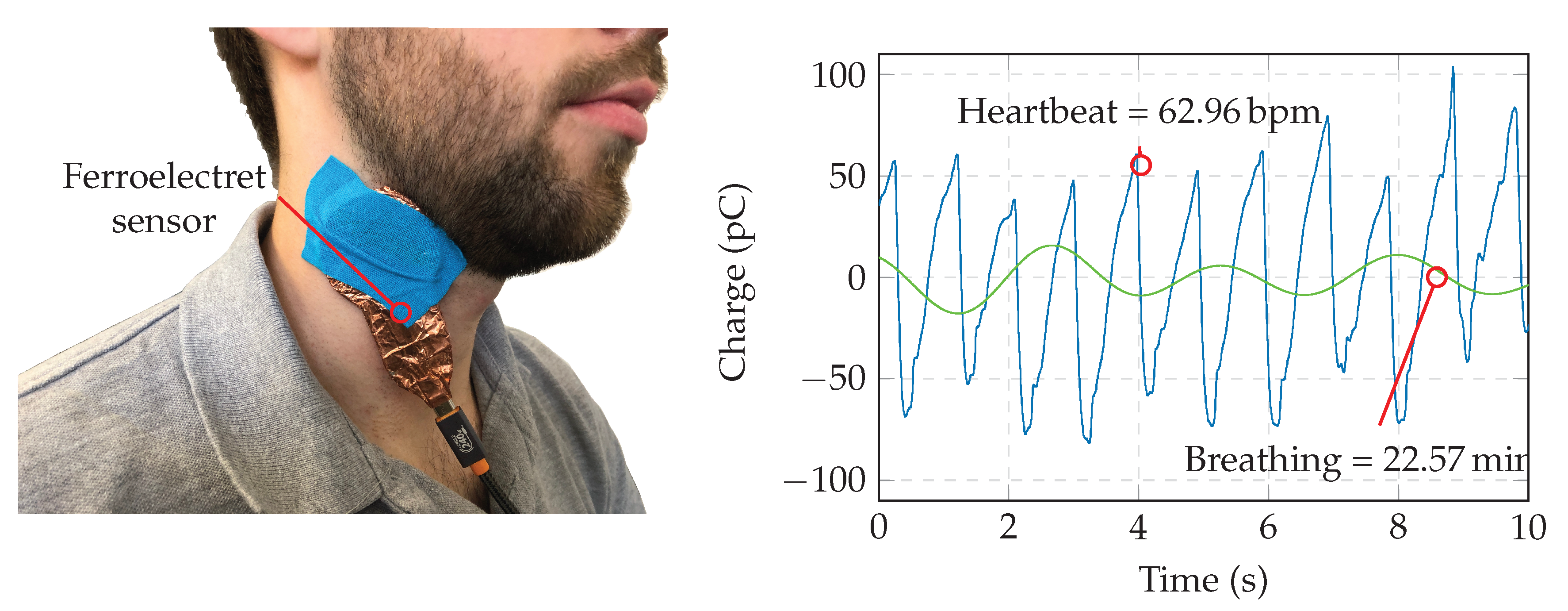
To demonstrate the applicability of the ChrisBox system in a physiological context, a pilot experiment was conducted in which a ferroelectret sensor was placed on the human neck to capture vital signals. The same sensor type as used in the EMI experiments was employed (Figure 6, left). The pulse could be directly identified in the raw signal (Figure 6, right, blue). After applying a bandpass filter in MATLAB with a passband of 0.2 Hz to 0.5 Hz, corresponding to a breathing rate of 12 min−1 to 30 min−1, respiratory activity also became clearly visible (Figure 6, right, green). The recorded raw signal exhibited an RMS charge amplitude of 42.8 pC, which corresponds to an SNR of approximately 53 dB.
In conclusion, ChrisBox provides a compact, open-source, and portable solution for high-resolution charge measurement with piezoelectric sensors. Its design emphasizes reproducibility, EMI robustness, and multi-channel scalability. Validation experiments demonstrated high agreement with a calibrated electrometer and robust performance under strong EMI exposure. The presented application example highlights the ability of ChrisBox to capture subtle biomechanical signals in a realistic setting. Taken together, these results establish ChrisBox as a versatile platform for research and teaching in sensing technologies, while offering a foundation for future application-specific developments in biomedical engineering, wearables, and beyond.
Future work will focus on extending ChrisBox towards fully wearable and wireless sensing applications. The current hardware can already operate on battery power and transmit data via Wi-Fi or Bluetooth; further miniaturization and low-power optimization would enable long-term continuous monitoring on the body. In addition, integration with textile-based ferroelectret sensors and multi-modal sensing units may open opportunities in unobtrusive health monitoring, rehabilitation, and sports science. On the metrological side, ongoing efforts will aim to further reduce low-frequency drift and expand calibration routines to support absolute force measurements. Finally, the open-source nature of the platform allows the community to adapt ChrisBox to diverse application domains, ranging from biomedical research to industrial condition monitoring. ChrisBox lowers the barrier for researchers to prototype and validate piezoelectric sensor systems.
Supplementary Materials
The following supporting information can be downloaded at: www.mdpi.com/xxx/s1 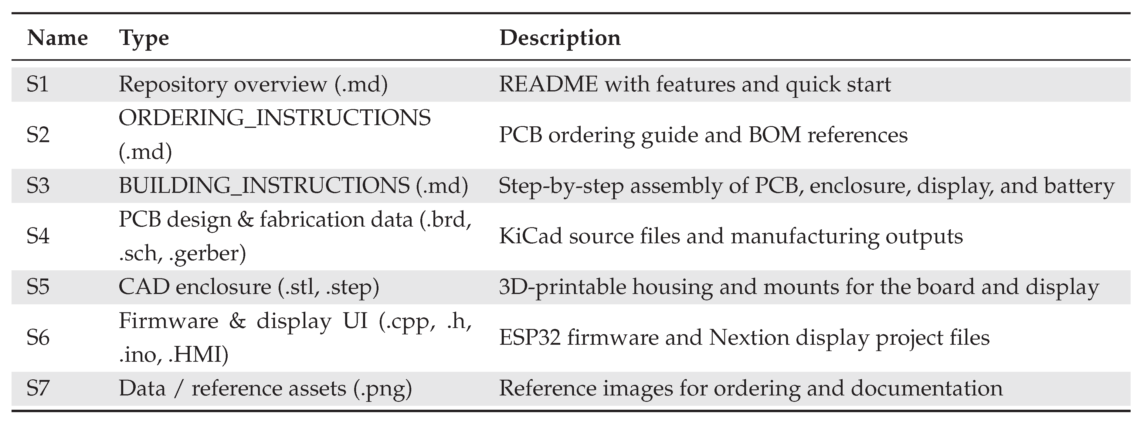
Author Contributions
Conceptualization, S.S., D.W., A.A., F.H., L.U., J.D., B.L., and M.K.; methodology, A.A. and S.S.; software, D.W., J.D., B.L., and S.S.; validation, L.U. and S.S.; resources, M.K.; writing—original draft preparation, S.S.; writing—review and editing, S.S., D.W., A.A., F.H., L.U., J.D., B.L., and M.K.; visualization, S.S. and F.H.; supervision & project administration, S.S., M.K.; All authors have read and agreed to the published version of the manuscript.
Funding
This research received support from the Deutsche Forschungsgemeinschaft (DFG) under grant no. 466650813 and no. 450821862. Under grant 101096884, Listen2Future is co-funded by the European Union. Views and opinions expressed are however those of the author(s) only and do not necessarily reflect those of the European Union or Chips Joint Undertaking. Neither the European Union nor the granting authority can be held responsible for them. The project is supported by the CHIPS JU and its members (including top-up funding by Austria, Belgium, Czech Republic, Germany, Netherlands, Norway and Spain).
Conflicts of Interest
The authors declare no conflicts of interest.
Appendix A. Bill of Materials
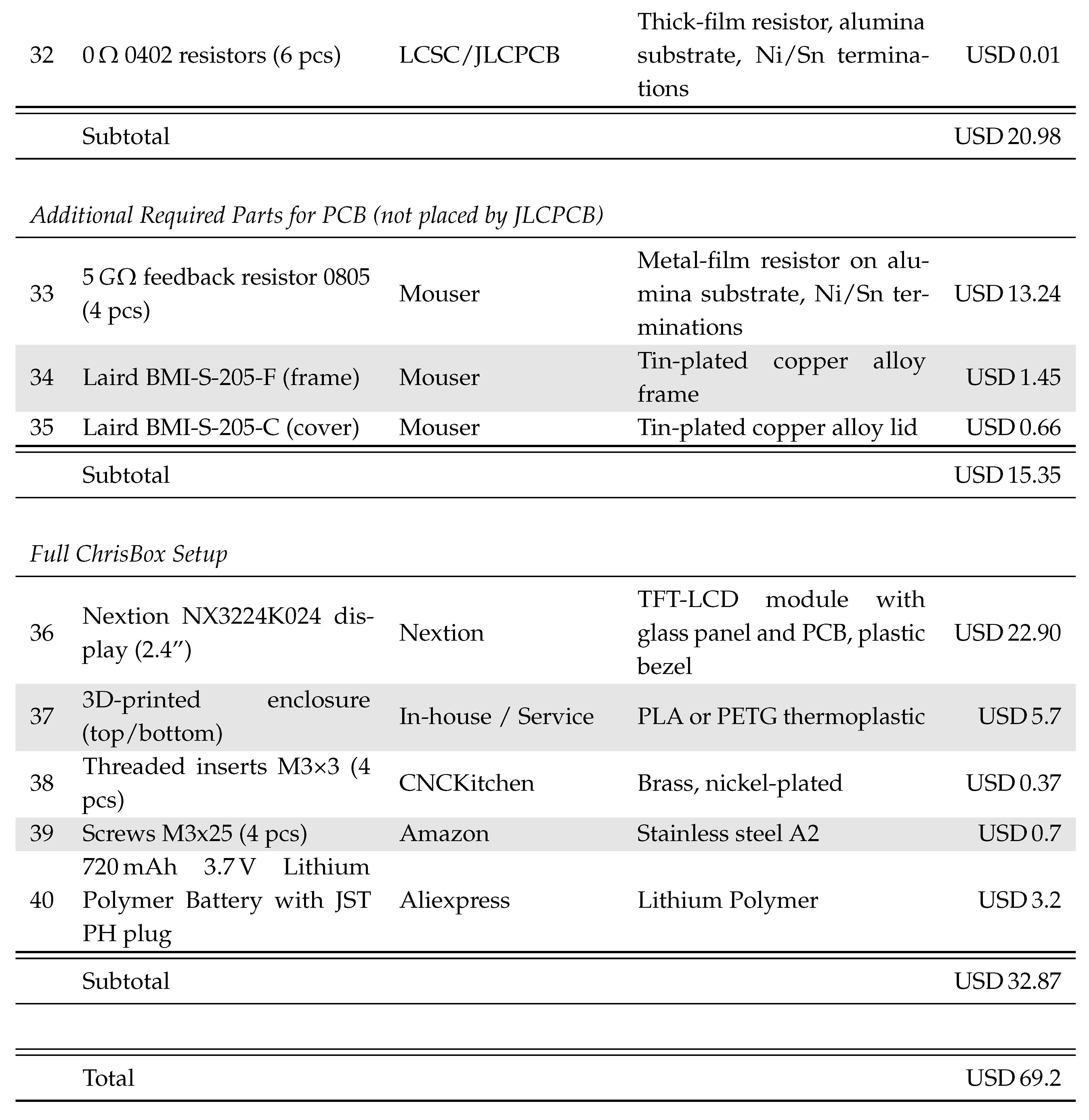
A precise cost estimation is inherently challenging, as it depends on multiple factors such as quantity discounts, currency exchange rates, supplier availability, and manufacturing location. The prices listed below are based on an indicative batch order of ten assembled units and have been normalized to the cost per single device. Variations in component selection or availability will occur over time. Please refer to the official project repository for the most recent information.
References
- Bauer, S.; Gerhard-Multhaupt, R.; Sessler, G.M. Ferroelectrets: Soft Electroactive Foams for Transducers. Physics Today 2004, 57, 37–43. [Google Scholar] [CrossRef]
- Wegener, M.; Bauer, S. Microstorms in cellular polymers: a route to soft piezoelectric transducer materials with engineered macroscopic dipoles. Chemphyschem : a European journal of chemical physics and physical chemistry 2005, 6, 1014–1025. [Google Scholar] [CrossRef] [PubMed]
- Sessler, G.M. (Ed.) Electrets; Vol. Vol. 33, Topics in applied physics, Springer: Berlin, Heidelberg, New York, 1980. [Google Scholar]
- Wang, N.; Zhang, H.; Qiu, X.; Gerhard, R.; van Turnhout, J.; Cressotti, J.; Zhao, D.; Tang, L.; Cao, Y. Recent Advances in Ferroelectret Fabrication, Performance Optimization, and Applications. Advanced materials (Deerfield Beach, Fla.) 2024, 36, e2400657. [Google Scholar] [CrossRef] [PubMed]
- Moreira, M.M.A.C.; Soares, I.N.; Assagra, Y.A.O.; Sousa, F.S.I.; Nordi, T.M.; Dourado, D.M.; Gounella, R.H.; Carmo, J.P.; Altafim, R.A.C.; Altafim, R.A.P. Piezoelectrets: A Brief Introduction. IEEE Sensors Journal 2021, 21, 22317–22328. [Google Scholar] [CrossRef]
- Altmann, A.A.; Suppelt, S.; Latsch, B.; Ben Dali, O.; Dörsam, J.H.; Thiem, D.G.E.; Kupnik, M. Flexible Shielded Sensors Based on Biocompatible Ferroelectrets for Heart Rate Monitoring. In Proceedings of the 2024 IEEE International Conference on Flexible and Printable Sensors and Systems (FLEPS). IEEE; 2024; pp. 1–4. [Google Scholar] [CrossRef]
- Qiu, X.; Bian, Y.; Liu, J.; Xiang, Y.; Ding, T.; Zhu, W.; Xuan, F.Z. Ferroelectrets: Recent developments. IET Nanodielectrics 2022, 5, 113–124. [Google Scholar] [CrossRef]
- von Seggern, H.; Zhukov, S.; Fedosov, S. Importance of geometry and breakdown field on the piezoelectric d 33 coefficient of corona charged ferroelectret sandwiches. IEEE Transactions on Dielectrics and Electrical Insulation 2011, 18, 49–56. [Google Scholar] [CrossRef]
- von Seggern, H.; Zhukov, S.; Dali, O.B.; Hartmann, C.; Sessler, G.M.; Kupnik, M. Highly Efficient Piezoelectrets through Ultra-Soft Elastomeric Spacers. Polymers 2021, 13. [Google Scholar] [CrossRef] [PubMed]
- Gong, S.; Zhang, B.; Zhang, J.; Wang, Z.L.; Ren, K. Biocompatible Poly(lactic acid)–Based Hybrid Piezoelectric and Electret Nanogenerator for Electronic Skin Applications. Advanced Functional Materials 2020, 30. [Google Scholar] [CrossRef]
- Assagra, Y.A.O.; Altafim, R.A.P.; do Carmo, J.P.; Altafim, R.A.C.; Rychkov, D.; Wirges, W.; Gerhard, R. A new route to piezo-polymer transducers: 3D printing of polypropylene ferroelectrets. IEEE Transactions on Dielectrics and Electrical Insulation 2020, 27, 1668–1674. [Google Scholar] [CrossRef]
- Olivato Assagra, Y.A.; Correa Altafim, R.A.; Pereira do Carmo, J.P.; Pisani Altafim, R.A. Well-defined piezoelectrets fabricated with 3D printing technology. In Proceedings of the 2016 IEEE International Conference on Dielectrics (ICD). IEEE; 2016; pp. 257–259. [Google Scholar] [CrossRef]
- Bae, J.H.; Chang, S.H. PVDF-based ferroelectric polymers and dielectric elastomers for sensor and actuator applications: a review. Functional Composites and Structures 2019, 1, 012003. [Google Scholar] [CrossRef]
- Wang, B.; Corsi, C.; Weiland, T.; Wang, Z.; Grund, T.; Pohl, O.; Bienia, J.M.; Weiss, J.; Ngo, H.D. Screen-Printed PVDF Piezoelectric Pressure Transducer for Unsteadiness Study of Oblique Shock Wave Boundary Layer Interaction. Micromachines 2024, 15. [Google Scholar] [CrossRef] [PubMed]
- Manh, L.N.; Li, J.; Kweon, H.; Chae, Y. Simultaneous measurement of two biological signals using a multi-layered polyvinylidene fluoride sensor. Scientific reports 2022, 12, 1507. [Google Scholar] [CrossRef] [PubMed]
- Pedotti, A.; Assente, R.; Fusi, G.; de Rossi, D.; Dario, P.; Domenici, C. Multisensor piezoelectric polymer insole for pedobarography. Ferroelectrics 1984, 60, 163–174. [Google Scholar] [CrossRef]
- Dai, Y.; Xie, Y.; Chen, J.; Kang, S.; Xu, L.; Gao, S. A lamination-based piezoelectric insole gait analysis system for massive production for Internet-of-health things. International Journal of Distributed Sensor Networks 2020, 16, 155014772090543. [Google Scholar] [CrossRef]
- Latsch, B.; Schäfer, N.; Grimmer, M.; Dali, O.B.; Mohseni, O.; Bleichner, N.; Altmann, A.A.; Schaumann, S.; Wolf, S.I.; Seyfarth, A.; et al. 3D-Printed Piezoelectric PLA-Based Insole for Event Detection in Gait Analysis. IEEE Sensors Journal 2024, 24, 26472–26486. [Google Scholar] [CrossRef]
- Diez, A.G.; Pereira, N.; Pinto, R.S.; Gonçalves, R.; Costa, C.M.; Lanceros-Mendez, S. Heart rate monitoring system based on piezoelectric poly(vinylidene fluoride-co-trifluoroethylene) composites with barium strontium titanate ceramic particles. Journal of Alloys and Compounds 2024, 989, 174372. [Google Scholar] [CrossRef]
- Sessler, G.M. Electrets; Vol. 33, Springer Berlin Heidelberg: Berlin, Heidelberg, 1987. [Google Scholar] [CrossRef]
- Tichý, J.; Erhart, J.; Kittinger, E.; Přívratská, J. Fundamentals of Piezoelectric Sensorics; Springer Berlin Heidelberg: Berlin, Heidelberg, 2010. [Google Scholar] [CrossRef]
- Alnasser, E. A Novel Low Output Offset Voltage Charge Amplifier for Piezoelectric Sensors. IEEE Sensors Journal 2020, 20, 5360–5367. [Google Scholar] [CrossRef]
- Jiang, D.; Li, P.; Yang, Y.; Xu, C. Development of a Miniature Charge Amplifier for Quasi-static Strain Measurement with PVDF Piezoelectric Film Sensors. In Proceedings of the 6th International Conference on Structural Health Monitoring and Integrity Management, Zhengzhou, 2024., 8 - 10 November 2024. [Google Scholar] [CrossRef]
- Crenna, F.; Rossi, G.B.; Berardengo, M. Filtering Biomechanical Signals in Movement Analysis. Sensors 2021, 21. [Google Scholar] [CrossRef] [PubMed]
Figure 1.
ChrisBox: An open-source, portable four-channel charge-measurement interface for piezoelectric sensors, such as flexible ferroelectret sensors. The single-board device integrates a microcontroller, four low-noise charge amplifiers with four 24-bit ADCs, shielding to suppress interference, and four sensor connectors. The shielding is partially cut in this visualization to enable a view of the underlying ADCs, and an enclosure is available for 3D printing. The board can be powered via USB or an optional battery and can drive an optional display for on-device waveform visualization. The board enables high-quality measurements of, e.g., body-worn ferroelectret sensors (right).

Figure 2.
Schematic overview of the four identical charge amplifier channels in ChrisBox. Each channel implements a transimpedance topology with a low-leakage op-amp, a feedback capacitor that sets the charge-to-voltage gain (), and a large feedback resistor that defines the low-frequency corner. A guarded, high-impedance input interfaces the piezoelectric sensors. All channels share a low-noise mid-supply reference .
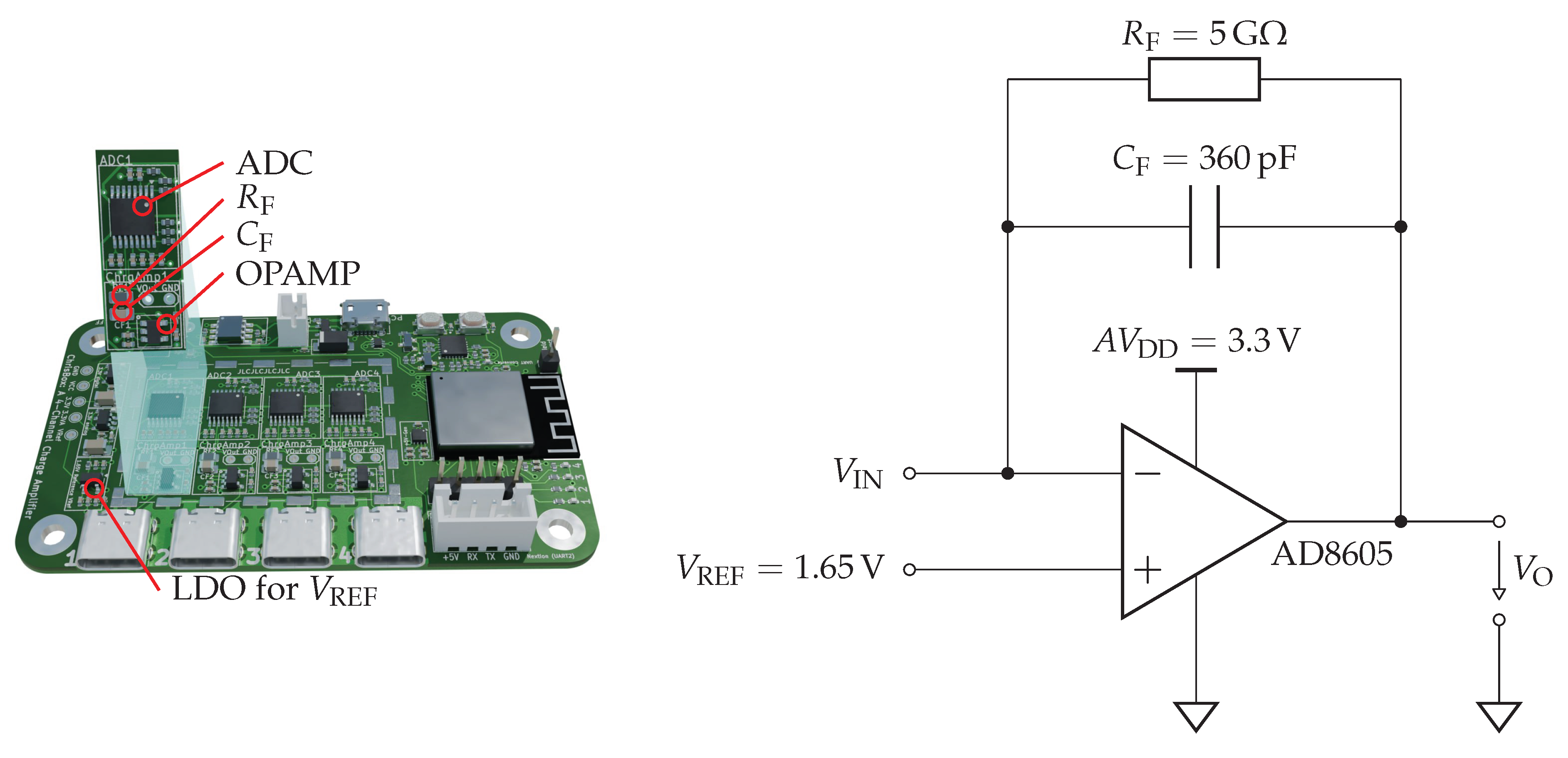
Figure 3.
Exploded view (left) and fully assembled ChrisBox (right). The device integrates the custom PCB, optional touchscreen display, and battery into a 3D-printed enclosure. The repository includes an alternative housing without the display cutout, for use when no display is needed.
Figure 3.
Exploded view (left) and fully assembled ChrisBox (right). The device integrates the custom PCB, optional touchscreen display, and battery into a 3D-printed enclosure. The repository includes an alternative housing without the display cutout, for use when no display is needed.
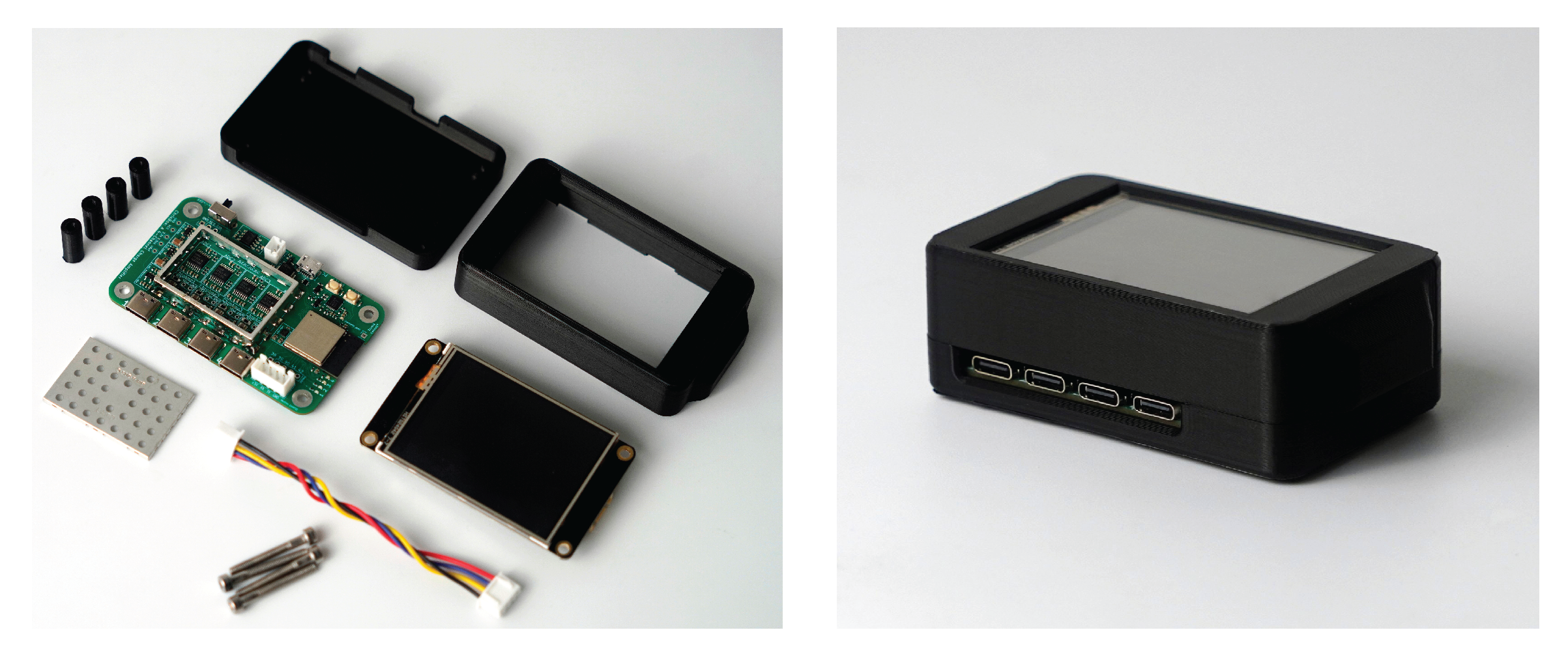
Figure 4.
Verification of the ChrisBox against a commercial electrometer. (a) Measurement setup with ferroelectret sensor mounted in a universal testing machine. (b) Example charge signals for both the commercial system (top) and the ChrisBox (bottom), when a load (grey) of 25 mN is applied and rapidly removed. The commercial electrometer integrates charge over time, providing an absolute measurement, whereas the ChrisBox charge amplifier employs AC coupling with a defined lower cutoff frequency, resulting in transient responses to force changes. (c) Comparison of measured charge across five force levels with repetitions each. Error bars indicate 95% confidence intervals. A linear regression shows a strong correlation with .
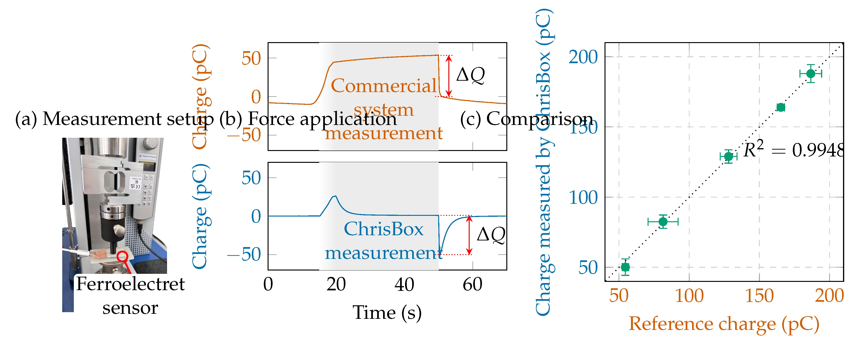
Figure 5.
Experimental setup with the ferroelectret sensor placed inside the TEM cell while connected to ChrisBox via a shielded cable (left) for EMI testing of ChrisBox. Right: RMS noise levels as a function of frequency for three configurations: removed shield with USB 2.0 cable (orange), installed shield with USB 2.0 cable (green), and installed shield with fully featured USB Type-C cable (blue). Comprehensive shielding, including both the PCB shield and a fully featured cable, reduces noise levels to below RMS across the tested frequency range.
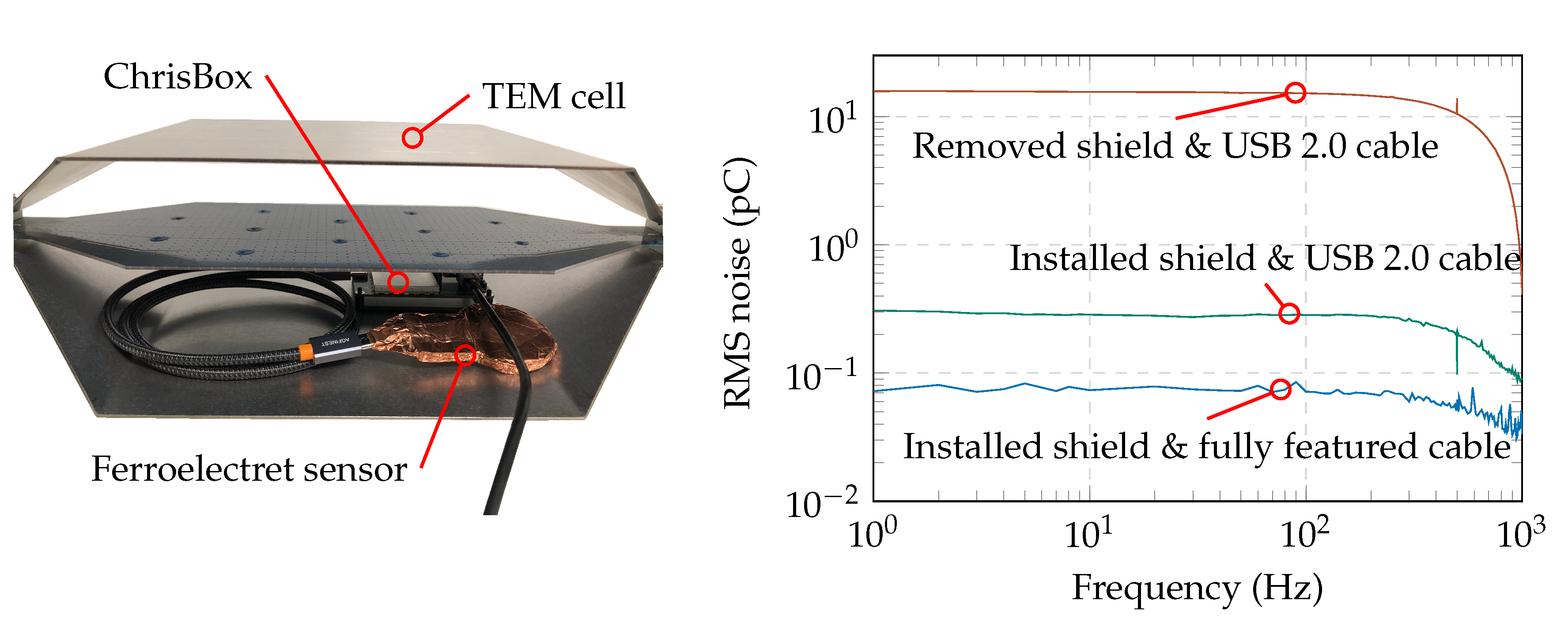
Figure 6.
Physiological signal measurement with ChrisBox. A ferroelectret sensor was placed on the neck to capture charge signals related to respiration and heartbeat. The RMS charge was 42.8 pC, corresponding to an SNR of approximately 53 dB. The breathing rate can be seen directly in the raw signal (blue), and when filtered, the breathing rate also becomes visible (green).
Short Biography of Authors
 |
Sven Supppelt received the M.Sc. degree in electrical engineering from Technische Universität Darmstadt, Germany, in 2021. Since then, he has been a Research Associate with the Measurement and Sensor Technology Group, Technische Universität Darmstadt. His research focuses on developing electronics, firmware, and software for embedded systems, with a strong emphasis on miniaturizing and integrating force sensors. He is particularly interested in medical systems, especially in the dental field. |
 |
Dominik Werner received the B.Sc. degree in mechatronic engineering from Technische Universität Darmstadt, Germany, in 2025. His research interests include electronics, mechanical sensors, and additive manufacturing processes. |
 |
Alexander A. Altmann received the M.Sc. degree in information systems technology from the Technische Universität Darmstadt, Germany, in 2021. Since 2022, he has been a Research Associate with the Measurement and Sensor Technology Group, Technische Universität Darmstadt. His research interests include the additive manufacturing of flexible sensors based on ferroelectrets and the integration into human-centric applications, such as textile integration or medical applications. |
 |
Felix Herbst received the M.Sc. degree in electrical engineering from Technische Universität Darmstadt, Germany, in 2022. Since then he has been a Research Associate with the Measurement and Sensor Technology Group at Technische Universität Darmstadt. His research interests include the design of structural integrated mechanical sensors as well as robotics in medical applications. |
 |
Lukas Ulmer received the M.Sc. degree in electrical engineering from Technische Universität Darmstadt, Germany, in 2025. Since then he has been a Research Associate with the Measurement and Sensor Technology Group at Technische Universität Darmstadt. His research interests include additively manufactured ferroelectret sensors. |
 |
Jan Helge Dörsam received the M.Sc. degree in Electrical Engineering from Technische Universität Darmstadt, Germany, in 2021. Since then, he has been a Research Associate with the Measurement and Sensor Technology Group at the Technische Universität Darmstadt. His research interests include acoustic levitation for micro- and nanofluidics and high-power ultrasonic transducers. |
 |
Bastian Latsch received the M.Sc. and Ph.D. degrees in electrical engineering from Technische Universität Darmstadt, Darmstadt, Germany, in 2019 and 2024, respectively. Since then, he has been a Postdoctoral Researcher with the Measurement and Sensor Technology Group, Technische Universität Darmstadt. His research interests include sensors in human movement assistance and interfaces for human–machine interaction. |
 |
Mario Kupnik received the Diplom-Ingenieur degree in electrical engineering from Graz University of Technology, Austria, in 2000, and the Ph.D. degree in electrical engineering from the University of Leoben, Leoben, Austria, in 2004. From 2005 to 2011, he was working as a Postdoctoral Researcher, a Research Associate, and a Senior Research Scientist at the Edward L. Ginzton Laboratory, Stanford University, Stanford, CA, USA. From 2011 to 2014, he was a Full Professor of electrical engineering at the Brandenburg University of Technology, Cottbus, Germany. Since 2015, he has been a Full Professor at Technische Universität Darmstadt, Germany, where he is currently the Head of the Measurement and Sensor Technology Group. His research topics are micromachined sensors and actuators, multiphysics simulations, ferroelectrets, flowmetering of gases and liquids, ultrasound, electroacoustics, human-machine interaction and robotics. |
Disclaimer/Publisher’s Note: The statements, opinions and data contained in all publications are solely those of the individual author(s) and contributor(s) and not of MDPI and/or the editor(s). MDPI and/or the editor(s) disclaim responsibility for any injury to people or property resulting from any ideas, methods, instructions or products referred to in the content. |
© 2025 by the authors. Licensee MDPI, Basel, Switzerland. This article is an open access article distributed under the terms and conditions of the Creative Commons Attribution (CC BY) license (http://creativecommons.org/licenses/by/4.0/).
Copyright: This open access article is published under a Creative Commons CC BY 4.0 license, which permit the free download, distribution, and reuse, provided that the author and preprint are cited in any reuse.


