
Submitted:
19 November 2025
Posted:
20 November 2025
You are already at the latest version
Abstract
This work develops a design framework for hydrodynamic cavitation reactors featuring Venturi throats with a Reuleaux-triangle cross-section (VRA) and a twisted, controlled-swirl variant (VRAt). The framework links internal geometry and flow patterns to three objectives: increasing cavitation event density, improving spatial uniformity and guiding localization in target regions near the wall. Geometric indicators relate the perimeter-to-area ratio and cross-sectional area to pressure drop, nucleation-site availability and near-wall coverage, and are combined with a kinematic description of swirl-induced flow-path elongation in VRAt. At equal cross-sectional area, VRA increases the perimeter, enhances fluid–wall contact and is expected to support a more extended and homogeneous cavitation field than a circular throat. VRAt further extends the flow path, shifts the pressure minimum and intensifies near-wall localization of collapses, with potential benefits for selectivity and energy efficiency. This theoretical contribution is intended to inform the design and experimental validation of next-generation cavitating devices. The proposed criteria are expressed in measurable quantities and enable transparent comparison with circular Venturi designs, providing a basis for model development, control strategies and scale-up across applications such as water and wastewater treatment, food and beverage processing, bioenergy, biotechnology, fine chemicals, materials processing and thermal systems.
Keywords:
hydrodynamic cavitation
; process intensification
; Reuleaux Venturi reactors
; system design methodology
; geometric optimization
; swirling flow
; sustainable process engineering
1. Introduction
Hydrodynamic cavitation arises from controlled pressure variations that generate vapor cavities in a flowing liquid and induce their rapid collapse. The collapse of these cavities concentrates energy on very short time scales and within small volumes [1,2,3]. It generates micro-jets, shock waves, intense shear and hot spots that give rise to hydroxyl radicals. These effects intensify micromixing, renew the interfacial area and enhance mass transfer, thereby accelerating physical and chemical transformations in the liquid phase [2,3,4,5,6]. The spatial distribution and intensity of cavity collapses depend on the pressure field and on the reactor geometry [2,4,5,7,8,9,10,11].
In this work, geometry is treated as a process module that can be embedded in complex systems, with requirements formulated so as to be modeled, controlled and integrated without discontinuities.
Applications of hydrodynamic cavitation are cross-sector and span multiple process industries [7,8,12,13], including water and wastewater treatment [14,15,16,17,18,19,20,21,22,23,24,25,26,27], the food and beverage sector [28,29,30,31,32,33,34,35,36,37,38,39,40,41,42], brewing [43,44,45,46,47,48,49,50,51,52], bioenergy [53,54,55,56,57], biotechnology and pharmaceutical processing [58,59,60], fine chemicals [61,62,63,64], materials, composites and cosmetics [65,66,67], the pulp and paper, textile and leather sectors [68,69], oil and gas and the mining industry [70], cleaning-in-place and antifouling operations [71], thermal plants [72], agritech [73] and maritime applications [74].
These applications rely on combinations of oxidation phenomena, micro- and nanoemulsification, and enhanced mixing and mass transfer, underpinning broader process-intensification schemes.
Here, cavitation is interpreted as the result of geometric constraints imposed in the throat. For a given cross-sectional area, the perimeter-to-area ratio is the lumped parameter that controls the pressure drop between contraction and pressure recovery: at constant area, a larger perimeter yields a steeper pressure profile and a higher characteristic . In circular Venturi throats, is minimal; therefore, we adopt a Reuleaux triangle cross-section (VRA), a curve of constant width that, for the same area, exhibits a larger perimeter than the circle and, consequently, a higher . In what follows, we denote by the dimensionless geometric factor, defined as the perimeter-to-area ratio of the throat normalised by that of the reference circular cross-section. Figure 1 summarises the iso-area comparison and highlights and the resulting difference in as the only change.
On this basis, we employ the VRA configuration: the throat retains the Reuleaux triangle cross-section without torsion, and the flow remains axial along the duct centerline, as shown in the longitudinal section of Figure 2.
The twisted configuration is denoted VRAt, where t stands for twist. It introduces an axial twist of the VRA throat that imposes a co-rotating swirl: the streamlines follow a helical trajectory and the effective path length of the fluid increases with respect to the purely axial case, as shown in Figure 3.
Compared with the circular cross-section, both VRA and its swirling VRAt variant are designed to increase the density, uniformity and spatial localization of bubble collapses. The expected benefits include higher selectivity, shorter treatment times and more efficient use of energy, subject to experimental confirmation [75].
This contribution is framed within the broader context of process intensification and provides a design framework that supports the modelling, control and optimisation of unit operations. The reduction of reagent consumption and thermal loads supports clean, low-impact technologies. Retrofitting, modularity and integration into existing process lines promote circular-economy strategies and efficient use of resources. The analysis is theoretical and calls for experimental validation. Adopting a systems perspective, the work proposes design criteria that are useful for dynamic modelling and control and for integration into plant architectures.
2. Geometric Criteria for the Density, Uniformity, and Localization of Cavitation Events in Process Industries
Hydrodynamic cavitation concentrates energy in localized collapses of cavities generated by a pressure drop in a flowing liquid [1,2,3]. In a Venturi device, the fluid accelerates in the throat, and cavity collapses generate micro-jets, shock waves and strong shear-rate gradients, which are useful for selective fragmentation, fine emulsification and chemical activation without additional reagents or high temperatures [2,3,4,5,6]. Within this design framework, three objectives are pursued: the density of cavitation events, the uniformity of their spatial distribution and their localization in regions of interest, either near the wall, in the core or on active surfaces.
The intensity of the phenomenon is described by the cavitation number:
where is the upstream pressure, the vapor pressure, the density, and the fluid velocity in the throat [4,5].
Taking the circular cross-section as a reference, the perimeter-to-area ratio is relatively low. For the same cross-sectional area, the VRA (Reuleaux triangle) increases the perimeter and thus ; this enlarges the fluid–wall interface and can promote denser and more uniform cavitation. The theoretical relationship between pressure losses and can be summarised as:
From (2), it follows that, for the same cross-sectional area, the pressure drop in the VRA geometry is approximately 2.1 times that in the circular geometry [75]. Geometrically, the circle has the minimum perimeter, whereas the Reuleaux curve extends the boundary and increases ; from a fluid-dynamic standpoint, this may increase the number of wall nucleation sites and make the distribution of collapses more uniform.
The VRAt variant introduces an axial twist of the Reuleaux throat with a co-rotating swirl, which intensifies the localization of bubble collapses and cavity–wall interactions, with potential benefits in terms of treatment times and energy efficiency, while maintaining a physics-based and clean-label approach [75]. This framework highlights measurable variables and design parameters that are useful for simulation, modelling, and optimization.
2.1. Availability of Nucleation Sites
In this section, only geometric effects are considered, at fixed cross-sectional area, surface condition , and operating conditions, including the cavitation number . The aim is to compare the availability of nucleation sites along the wall between a circular throat (baseline) and a VRA throat.
The total number of nucleation sites available on the wall is proportional to the perimeter of the cross-section:
where is the total number of nucleation sites on the internal surface of the throat, is the linear density of active sites associated with the surface condition, and is the perimeter of the cross-section. To relate this availability to the area swept by the fluid, the surface density of nucleation sites is introduced:
where is the density of sites referred to the cross-sectional area and is the cross-sectional area; the ratio measures how much wall length is available per unit area of flow.
The relative geometric factor is defined as:
which compares the perimeter-to-area ratio of the VRA throat with that of the circular throat. For the same cross-sectional area, the VRA cross-section has a larger perimeter-to-area ratio than the circular one, , from which it follows that . Here is the dimensionless geometric factor defined in (5) as the ratio between the perimeter-to-area ratio of the VRA cross-section and that of the circular reference. Under the theoretical conditions specified above, this implies that the VRA throat exhibits a greater availability of nucleation sites along the wall than the circular throat, with potential benefits in terms of treatment speed and effectiveness.
2.2. Density of Sites and Probability of Cavitation Inception
In this section, only geometric effects are considered: the cross-sectional area , the surface condition described by the parameter , and the operating conditions, including the cavitation number , are kept fixed. The surface density of nucleation sites increases with the geometric ratio according to (4). Let denote the probability that a fluid element undergoes cavitation inception during a single passage through the throat, and let be the corresponding single-pass inception probability associated with an individual active site on the wall. Under a simple mean-field approximation, it is assumed that
For compact notation in the tables, we therefore use the lumped parameter , where is the linear density of active sites along the wall introduced in (3). Since is proportional to (4), and the geometric factor defined in (5) is greater than one for the VRA cross-section, both and are expected to be larger in the VRA throat than in the circular cross-section under the conditions considered. In practice, a higher density of active sites can sustain a higher frequency and a wider spatial spread of cavitation events.
2.3. Distribution of Cavitation Events
For an effective treatment, it is not sufficient to increase the number of events; cavitation inceptions must also be distributed along the entire internal wall of the Venturi throat. In this subsection, only geometric effects are considered at fixed cross-sectional area, operating conditions and surface state.
Let denote the fraction of the cross-sectional area lying within a distance from the wall. For cross-sections with a convex and smooth boundary and for sufficiently small , with smaller than both the inradius and the minimum radius of curvature, the following first-order approximation holds:
where is dimensionless, is the characteristic near-wall thickness, is the perimeter of the cross-section and is its area. In what follows, will also be used as a compact indicator of near-wall coverage in the comparative tables.
Equation (7) shows that the fraction of the cross-section close to the wall increases, to first order, with the ratio , consistently with the higher availability and density of nucleation sites summarized in (3) and (4). Since, at equal area, the VRA geometry exhibits a higher than the circular section, for the same the near-wall fraction is larger in the VRA case. This implies, in purely geometric terms, a wider azimuthal coverage of potential inceptions and a lower probability of poorly treated regions. For the same throat area, Figure 4 and Figure 5 provide a visual reference for understanding the effect of geometry on cavitation and for interpreting the parameters introduced.
2.4. Localization of Inceptions with Swirl (VRAt): Kinematic Effects Near the Wall
The assumptions of equal cross-sectional area, unchanged surface condition and identical operating conditions, including the cavitation number , still hold. In the VRAt configuration, the flow in the throat exhibits a co-rotating swirl, that is, a tangential component that forces the streamlines to follow a helical path. Let be the axial length of the throat, the effective path length, and the helix angle with respect to the axis. In a purely kinematic description, one obtains
For , it follows that ; under the same conditions, the swirl elongates the path and increases near-wall exposure. Let be a dimensionless index of swirl-induced near-wall localisation, used qualitatively in the tables; it increases with (or, equivalently, with the ratio ). Swirl does not modify the cross-sectional geometry and therefore does not change or ; instead, it acts on how inceptions are distributed within the near-wall region.
Since VRAt shares the VRA cross-sectional geometry, which exhibits a higher than the circular section, as reflected in the geometric factor defined in (5), and since the near-wall fraction increases with according to (7), the addition of swirl in VRAt can promote a sharper localisation of inception events along the perimeter. This behaviour is illustrated in Figure 5, where the near-wall swirl causes inception events to cluster at the cusps and to decay along the arcs. The combined effects of geometry and swirl are summarised in Table 1, which reports the relative geometric and inception-related metrics for the circular, VRA and VRAt configurations.
3. Future Application Perspectives of the VRA and VRAt Geometries
Building on the application areas of hydrodynamic cavitation outlined in Section 1, the VRA geometry increases the wetted perimeter and the fluid–wall contact, which can lead to cavitation collapse fields that are denser and more uniform. The VRAt variant introduces a controlled swirl that extends the effective path length and helps localise the action near the regions of interest. These design choices aim to combine selectivity with short treatment times across multiple application domains.
In water and wastewater treatment, higher density and improved uniformity of collapses can sustain advanced oxidation of micropollutants, reduction of colour and organic load, mild disinfection and conditioning of streams for coagulation, flotation and membrane processes with reduced fouling. Near-wall localisation, including on catalytic supports, can promote selective activation and synergies with oxidants [15,18,26,69].
In food processing, the combination of shear, micro-jets and shock waves can support low-temperature sanitisation, rapid extraction of bioactive compounds, stable emulsions and clarification [28,29,32,33,38,40].
In brewing and in dairy and plant-based beverages, these effects can be exploited for intensified boiling and isomerisation, homogenisation and stabilisation [43,45,46,48,50,62].
In bioenergy, there are prospects for sludge disintegration, microalgae lysis and substrate preparation for anaerobic digestion with increased biogas yield, as well as for fine reactive emulsions that accelerate continuous transesterification in biodiesel production [54,55,56,57].
In biotechnology and pharmaceutical processing, controlled lysis, micromixing and nanoemulsion formation can improve the recovery of intracellular products and the delivery of active ingredients [58,59,60].
In fine chemicals, homogeneous catalyst dispersion and the management of reactive emulsions can favour oxidations and other liquid-phase syntheses, while in materials and composites, nanofiller dispersion and rheological control can benefit from more regular collapse fields [61,62,63,66,67].
Other scenarios include the pulp and paper, textile and leather sectors, with mild bleaching treatments and reduced effluents; oil and gas, with treatment of produced water, oxidative desulfurisation and cleaning of heat exchangers; mining and hydrometallurgy, with more effective leaching and flotation; and cosmetics, with fine emulsions and well-dispersed pigments [68,69,70,71].
In cleaning-in-place and antifouling operations, the removal of biofilms and scale deposits may become faster. Hydrodynamic cavitation reactors implemented in recirculating water-treatment loops and in strongly cavitating shear flows have been shown to enhance mass- and heat-transfer phenomena; on this basis, in thermal circuits and heating, ventilation and air-conditioning (HVAC) systems, degassing and the recovery of heat-transfer performance may become more efficient [71,72].
In agritech, there are prospects for water sanitisation, extraction of biostimulants and preparation of pesticide emulsions, while in food packaging, logistics and marine applications, further opportunities can be envisaged in washing waters, edible coatings and biofouling management in recirculating systems [31,32,33,73,74].
4. Conclusions
This theoretical study links internal reactor geometry and pressure fields to cavitation behaviour. The comparison at equal cross-sectional area, surface condition and operating conditions highlights three design objectives: increasing the density of events, improving their uniformity and guiding their localisation in regions of interest.
The VRA geometry expands the effective perimeter and the fluid–wall contact. This leads to a greater availability of nucleation sites, a higher site density per unit area and a more extended near-wall coverage. The distribution of inceptions becomes more regular and the cavitation field more coherent.
The VRAt variant introduces a controlled swirl. The rotational component lengthens the effective path, increases the useful residence time near the wall and makes the pressure distribution more favourable. The action becomes more concentrated where it is needed, with potential benefits in terms of selectivity and treatment quality. These results provide guidance for the design and comparative assessment of cavitation reactors.
The next step is experimental: measuring, calibrating and benchmarking these geometries against circular throats at the same scale and with the same average power, using in-line measurements and reproducible protocols. The framework is intended to be useful to researchers, process engineers, quality and safety managers, and energy and sustainability officers.
More broadly, the proposed picture is consistent with an efficiency-oriented view of conversion processes and their integration into energy systems. It supports design, control and scalability criteria for process engineering, promotes clean technologies and favours efficient resource use and circular-economy strategies.
Within this logic, the VRA geometry aims at a higher density and greater uniformity of cavitation events, whereas the swirling variant strengthens their localisation and can shorten treatment times and reduce energy consumption at a given process target.
Author Contributions
Conceptualization, L.A.; methodology, L.A. and R.D.; formal analysis, L.A. and R.D.; investigation, L.A. and R.D.; data curation, L.A.; visualization, S.F.D.G. and R.D.; writing—original draft preparation, L.A.; writing—review and editing, L.A., S.F.D.G., R.D. and F.M.; supervision, L.A. and R.D.; project administration, L.A. All authors have read and agreed to the published version of the manuscript.
Funding
This research received no external funding.
Data Availability Statement
The original contributions presented in this study are included in this article. Further inquiries can be directed to the corresponding author.
Conflicts of Interest
The authors declare no conflict of interest.
Abbreviations
The following abbreviations are used in this manuscript:
| VRA | Venturi Reuleaux Albanese |
| VRAt | Venturi Reuleaux Albanese twist |
References
- Pandit, A.B.; Gogate, P.R. A review and assessment of hydrodynamic cavitation as a technology for the future. Ultrason. Sonochem. 2005, 12, 21–27. [Google Scholar] [CrossRef]
- Thanekar, P.; Gogate, P. Application of Hydrodynamic Cavitation Reactors for Treatment of Wastewater Containing Organic Pollutants: Intensification Using Hybrid Approaches. Fluids 2018, 3, 98. [Google Scholar] [CrossRef]
- Tang, S.; Yu, H.; Li, Y.; Zhang, D.; Wang, Y.; Liu, X. Mechanistic and synergistic aspects of ultrasonics and hydrodynamic cavitation for food processing. Crit. Rev. Food Sci. Nutr. 2023, 63, 1988–2003. [Google Scholar] [CrossRef] [PubMed]
- Brennen, C.E. Cavitation and Bubble Dynamics; Oxford University Press: Oxford, UK, 1995. [Google Scholar] [CrossRef]
- Franc, J.P.; Michel, J.M. Fundamentals of Cavitation; Kluwer Academic Publishers: Dordrecht, The Netherlands, 2004. [Google Scholar] [CrossRef]
- Senthilkumar, P.; Sivakumar, M.; Pandit, A.B. Experimental Quantification of Chemical Effects of Hydrodynamic Cavitation. Chem. Eng. Sci. 2000, 55, 1633–1639. [Google Scholar] [CrossRef]
- Carpenter, J.; Badve, M.; Rajoriya, S.; Pandit, A.B. Hydrodynamic cavitation: An emerging technology for the intensification of various chemical and physical processes in a chemical process industry. Rev. Chem. Eng. 2016, 32, 1–52. [Google Scholar] [CrossRef]
- Zheng, H.; Zheng, Y.; Zhu, J. Recent developments in hydrodynamic cavitation reactors: Cavitation mechanism, reactor design, and applications. Engineering 2022, 19, 180–198. [Google Scholar] [CrossRef]
- Bashir, T.A.; Soni, A.G.; Mahulkar, A.V.; Pandit, A.B. The CFD Driven Optimization of a Modified Venturi for Cavitation Activity. Can. J. Chem. Eng. 2011, 89, 1366–1375. [Google Scholar] [CrossRef]
- Li, M.; Bussonnière, A.; Bronson, M.; Xu, Z.; Liu, Q. Study of Venturi tube geometry on the hydrodynamic cavitation for the generation of microbubbles. Miner. Eng. 2019, 132, 268–274. [Google Scholar] [CrossRef]
- Nadiri, K.; Baradaran, S. Geometric Optimization of Venturi Reactors for Enhanced Hydrodynamic Cavitation Efficiency: From Conventional to Advanced Tandem Configurations. Chem. Eng. J. Adv. 2025, 24, 100844. [Google Scholar] [CrossRef]
- Malkapuram, S.T.; Sonawane, S.H. Intensified Physical and Chemical Processing Using Cavitation: How Far Are We from Commercial Applications of Hydrodynamic Cavitation? Curr. Opin. Chem. Eng. 2025, 49, 101154. [Google Scholar] [CrossRef]
- Galloni, M.G.; Fabbrizio, V.; Giannantonio, R.; Falletta, E.; Bianchi, C.L. Applications and Applicability of the Cavitation Technology. Curr. Opin. Chem. Eng. 2025, 48, 101129. [Google Scholar] [CrossRef]
- Sivakumar, M.; Pandit, A.B. Wastewater Treatment: A Novel Energy Efficient Hydrodynamic Cavitational Technique. Ultrason. Sonochem. 2002, 9, 123–131. [Google Scholar] [CrossRef]
- Gogate, P.R. Cavitation: An Auxiliary Technique in Wastewater Treatment Schemes. Adv. Environ. Res. 2002, 6, 335–358. [Google Scholar] [CrossRef]
- Gogate, P.R.; Pandit, A.B. A Review of Imperative Technologies for Wastewater Treatment I: Oxidation Technologies at Ambient Conditions. Adv. Environ. Res. 2004, 8, 501–551. [Google Scholar] [CrossRef]
- Darandale, G.R.; Jadhav, M.V.; Warade, A.R.; Hakke, V.S. Hydrodynamic cavitation a novel approach in wastewater treatment: A review. Mater. Today Proc. 2023, 77, 960–968. [Google Scholar] [CrossRef]
- Bagal, M.V.; Gogate, P.R. Wastewater Treatment Using Hybrid Treatment Schemes Based on Cavitation and Fenton Chemistry: A Review. Ultrason. Sonochem. 2014, 21, 1–14. [Google Scholar] [CrossRef]
- Rayaroth, M.P.; Federov, K.; Boczkaj, G.; Patil, Y.; Sonawane, S.H. Chapter 5 – Hydrodynamic Cavitation in Wastewater Treatment. In Advanced Technologies in Wastewater Treatment; Castro-Muñoz, R., Basile, A., Cassano, A., Eds.; Elsevier, 2025; pp. 115–145. [Google Scholar] [CrossRef]
- Song, Y.; Guan, S.; Wang, Y.; Zhang, C.; Liu, J.; Zhang, L. The Application of Hydrodynamic Cavitation Technology and the Synergistic Effect of Hybrid Advanced Oxidation Processes: A Review. Water Sci. Technol. 2025, 92, 301–325. [Google Scholar] [CrossRef]
- Yeneneh, A.M.; Al Balushi, K.; Jafary, T.; Al Marshudi, A.S.; Chittance, L.R.; Ben, L.S.; Ibrahim, H.A. Hydrodynamic Cavitation and Advanced Oxidation for the Treatment of Persistent Organic Pollutants: A Review. Sustainability 2024, 16, 4601. [Google Scholar] [CrossRef]
- Khiadani, M.; Taheri, E.; Bobade, V.; Fatehizadeh, A. Enhanced Degradation of Triclosan Using Aerated Hydrodynamic Cavitation: Turbulence-Based Modelling and Economic Evaluation. npj Clean Water 2025, 8, 89. [Google Scholar] [CrossRef]
- Verdini, F.; Crudo, D.; Bosco, V.; Kamler, A.V.; Cravotto, G.; Calcio Gaudino, E. Advanced Processes in Water Treatment: Synergistic Effects of Hydrodynamic Cavitation and Cold Plasma on Rhodamine B Dye Degradation. Processes 2024, 12, 2128. [Google Scholar] [CrossRef]
- Vásquez Llanos, S.; Mesia Chuquizuta, J.; Sanchez Purihuaman, M.; Carreño Farfan, C.; Ancieta Dextre, C.; Carrasco Venegas, L.; Córdova Rojas, L.; Díaz Bravo, P.; Medina Collana, J.; Barturen Quispe, A. Hydrodynamic Cavitation for Vinasse Treatment: Optimization Using the Taguchi Method and Phytotoxicity Evaluation. Chem. Eng. Trans. 2025, 118, 379–384. [Google Scholar] [CrossRef]
- Alsadik, A.; Akintunde, O.O.; Habibi, H.R.; Lebeau, T.; Xu, J.; Chen, Z.; Liu, F.; Achari, G. PFAS in Water Environments: Recent Progress and Challenges in Monitoring, Toxicity, Treatment Technologies, and Post-Treatment Toxicity. Environ. Syst. Res. 2025, 14, 18. [Google Scholar] [CrossRef]
- Kosel, J.; Gutiérrez-Aguirre, I.; Rački, N.; Dreo, T.; Ravnikar, M.; Dular, M. Efficient Inactivation of MS-2 Virus in Water by Hydrodynamic Cavitation. Water Res. 2017, 124, 465–471. [Google Scholar] [CrossRef] [PubMed]
- Sawant, S.S.; Anil, A.C.; Krishnamurthy, V.; Gaonkar, C.; Kolwalkar, J.; Khandeparker, L.; Desai, D.; Mahulkar, A.V.; Ranade, V.V.; Pandit, A.B. Effect of Hydrodynamic Cavitation on Zooplankton: A Tool for Disinfection. Biochem. Eng. J. 2008, 42, 320–328. [Google Scholar] [CrossRef]
- Nye-Wood, M.G.; Byrne, K.; Stockwell, S.; Juhász, A.; Bose, U.; Colgrave, M.L. Low Gluten Beers Contain Variable Gluten and Immunogenic Epitope Content. Foods 2023, 12, 3252. [Google Scholar] [CrossRef]
- Arya, S.S.; More, P.R.; Ladole, M.R.; Pegu, K.; Pandit, A.B. Non-thermal, energy efficient hydrodynamic cavitation for food processing, process intensification and extraction of natural bioactives: A review. Ultrason. Sonochem. 2023, 98, 106504. [Google Scholar] [CrossRef]
- Asaithambi, N.; Singha, P.; Singh, S.K. Hydrodynamic cavitation and its application in food and beverage industry: A review. J. Food Process Eng. 2019, 42, e13144. [Google Scholar] [CrossRef]
- Zoglopiti, E.; Roufou, S.; Psakis, G.; Okafor, E.T.; Dasenaki, M.; Gatt, R.; Valdramidis, V.P. Unravelling the Hydrodynamic Cavitation Potential in Food Processing: Underlying Mechanisms, Crucial Parameters, and Antimicrobial Efficacy. Food Eng. Rev. 2025. [Google Scholar] [CrossRef]
- Garcia Bustos, K.A.; Rossetti, C.; Frascarelli, D.; Brunori, G. Hydrodynamic cavitation as a promising technology for fresh produce-based beverages processing. Innov. Food Sci. Emerg. Technol. 2024, 96, 103784. [Google Scholar] [CrossRef]
- Wu, Z.; Ferreira, D.F.; Crudo, D.; Bosco, V.; Stevanato, L.; Costale, A.; Cravotto, G. Plant and biomass extraction and valorisation under hydrodynamic cavitation. Processes 2019, 7, 965. [Google Scholar] [CrossRef]
- Raj, A.S. Advancing phytonutrient extraction via cavitation-based methodology: Exploring catechin recovery from Camellia sinensis leaves. Biocatal. Agric. Biotechnol. 2023, 54, 102895. [Google Scholar] [CrossRef]
- Ciriminna, R.; Scurria, A.; Pagliaro, M. Natural Product Extraction via Hydrodynamic Cavitation. Sustain. Chem. Pharm. 2023, 33, 101083. [Google Scholar] [CrossRef]
- Manoharan, D.; Zhao, J.; Ranade, V.V. Cavitation technologies for extraction of high value ingredients from renewable biomass. TrAC Trends Anal. Chem. 2024, 174, 117682. [Google Scholar] [CrossRef]
- Soyama, H.; Hiromori, K.; Shibasaki-Kitakawa, N. Simultaneous extraction of caffeic acid and production of cellulose microfibrils from coffee grounds using hydrodynamic cavitation in a Venturi tube. Ultrason. Sonochem. 2024, 108, 106964. [Google Scholar] [CrossRef]
- Sun, X.; Xuan, X.; Ji, L.; Chen, S.; Liu, J.; Zhao, S.; Park, S.; Yoon, J.Y.; Om, A.S. A novel continuous hydrodynamic cavitation technology for the inactivation of pathogens in milk. Ultrason. Sonochem. 2021, 71, 105382. [Google Scholar] [CrossRef]
- Xue, L.; Hao, Z.; Manickam, S.; Liu, G.; Wang, H.; Sun, X.; Bie, H. ; Evaluation of Disinfection and Cavitation Performance of a Cylindrical Rotational Hydrodynamic Cavitation Reactor: Influence of Key Geometric Parameters of the Cavitation Generation Unit. Ultrason. Sonochem. 2025, 121, 107544. [Google Scholar] [CrossRef]
- Boček, Ž.; Procházka, J.; Málek, J.; Szymański, P.; Veverka, P. Kelvin–Helmholtz instability as one of the key features for fast and efficient emulsification by hydrodynamic cavitation. Ultrason. Sonochem. 2024, 108, 106970. [Google Scholar] [CrossRef]
- Hua, N.; Ren, X.; Yang, F.; Huang, Y.; Wei, F.; Yang, L. The Effect of Hydrodynamic Cavitation on the Structural and Functional Properties of Soy Protein Isolate–Lignan/Stilbene Polyphenol Conjugates. Foods 2024, 13, 3609. [Google Scholar] [CrossRef] [PubMed]
- Fleite, S.N.; Balbi, M.d.P.; Ayude, M.A.; Cassanello, M. Rheological Features of Aqueous Polymer Solutions Tailored by Hydrodynamic Cavitation. Fluids 2025, 10, 169. [Google Scholar] [CrossRef]
- Albanese, L.; Ciriminna, R.; Meneguzzo, F.; Pagliaro, M. Beer-brewing powered by controlled hydrodynamic cavitation: Theory and real-scale experiments. J. Clean. Prod. 2017, 142, 1457–1470. [Google Scholar] [CrossRef]
- Albanese, L.; Ciriminna, R.; Meneguzzo, F.; Pagliaro, M. Beer produced via hydrodynamic cavitation retains higher amounts of xanthohumol and other hops prenylflavonoids. LWT. 2018, 256, 357–363. [Google Scholar] [CrossRef]
- Meneguzzo, F.; Albanese, L. Intensification of the Dimethyl Sulfide Precursor Conversion Reaction: A Retrospective Analysis of Pilot-Scale Brewer’s Wort Boiling Experiments Using Hydrodynamic Cavitation. Beverages 2025, 11, 22. [Google Scholar] [CrossRef]
- Albanese, L.; Ciriminna, R.; Meneguzzo, F.; Pagliaro, M. Gluten reduction in beer by hydrodynamic cavitation assisted brewing of barley malts. LWT–Food Sci. Technol. 2017, 82, 342–353. [Google Scholar] [CrossRef]
- Albanese, L.; Ciriminna, R.; Meneguzzo, F.; Pagliaro, M. Innovative beer-brewing of typical, old and healthy wheat varieties to boost their spreading. J. Clean. Prod. 2018, 171, 297–311. [Google Scholar] [CrossRef]
- Albanese, L.; Meneguzzo, F. Hydrodynamic Cavitation-Assisted Processing of Vegetable Beverages: Review and the Case of Beer-Brewing. In Production and Management of Beverages; Grumezescu, A.M., Holban, A.M., Eds.; Woodhead Publishing: Cambridge, UK, 2019; pp. 211–257. [Google Scholar] [CrossRef]
- Meneguzzo, F.; Albanese, L.; Zabini, F. Hydrodynamic Cavitation in Beer and Other Beverage Processing. In Innovative Food Processing. In Innovative Food Processing Technologies; Knoerzer, K., Muthukumarappan, K., Eds.; Elsevier: Cambridge, UK, 2021; pp. 369–394. [Google Scholar] [CrossRef]
- Štěrba, J.; Punčochář, M.; Brányik, T. The effect of hydrodynamic cavitation on isomerization of hop alpha-acids, wort quality and energy consumption during wort boiling. Food Bioprod. Process. 2024, 144, 214–219. [Google Scholar] [CrossRef]
- Yu, J.; Qin, J.; Sun, H.; Ruan, Y.; Fang, D.; Wang, J. The changes induced by hydrodynamic cavitation treatment in wheat gliadin and celiac-toxic peptides. J. Food Sci. Technol. 2024, 61, 1976–1985. [Google Scholar] [CrossRef]
- Simões, A.M.A. Application of Hydrodynamic Cavitation in Brewing: Impacts on Gluten Levels and Process Efficiency; Master’s Thesis, Universidade do Minho, Braga, Portugal, 2022. Available online: https://repositorium.uminho.pt/entities/publication/22813ddc-5821-4a4d-a1e3-e981bffa726d. [Google Scholar]
- Montusiewicz, A.; Pasieczna-Patkowska, S.; Lebiocka, M.; Szaja, A.; Szymańska-Chargot, M. Hydrodynamic cavitation of brewery spent grain diluted by wastewater. Chem. Eng. J. 2017, 313, 946–956. [Google Scholar] [CrossRef]
- Zieliński, M.; Dębowski, M.; Kazimierowicz, J.; Nowicka, A.; Dudek, M. Application of Hydrodynamic Cavitation in the Disintegration of Aerobic Granular Sludge—Evaluation of Pretreatment Time on Biomass Properties, Anaerobic Digestion Efficiency and Energy Balance. Energies 2024, 17, 335. [Google Scholar] [CrossRef]
- Waghmare, A.; Nagula, K.; Pandit, A.; Arya, S. Hydrodynamic cavitation for energy efficient and scalable process of microalgae cell disruption. Algal Res. 2019, 40, 101496. [Google Scholar] [CrossRef]
- Mittal, R.; Ranade, V.V. Bioactives from microalgae: A review on process intensification using hydrodynamic cavitation. J. Appl. Phycol. 2023, 35, 1129–1161. [Google Scholar] [CrossRef]
- Vera-Rozo, J.R.; Caicedo-Peñaranda, E.A.; Riesco-Avila, J.M. Hydrodynamic Cavitation in Shockwave-Power-Reactor-Assisted Biodiesel Production in Continuous from Soybean and Waste Cooking Oil. Energies 2025, 18, 2761. [Google Scholar] [CrossRef]
- Save, S.S.; Pandit, A.B.; Joshi, J.B. Microbial cell disruption: role of cavitation. Chem. Eng. J. Biochem. Eng. J. 1994, 55, B67–B72. [Google Scholar] [CrossRef]
- Balasundaram, B.; Harrison, S.T.L. Disruption of Brewers' yeast by hydrodynamic cavitation: Process variables and their influence on selective release. Biotechnol. Bioeng. 2006, 94, 303–311. [Google Scholar] [CrossRef]
- Gogate, P.R.; Kabadi, A.M. A review of applications of cavitation in biochemical engineering/biotechnology. Biochem. Eng. J. 2009, 44, 60–72. [Google Scholar] [CrossRef]
- Saharan, V.K.; Pandit, A.B.; SatishKumar, P.S.; Anandan, S. Hydrodynamic cavitation as an advanced oxidation technique for the degradation of Acid Red 88 dye. Ind. Eng. Chem. Res. 2012, 51, 1981–1989. [Google Scholar] [CrossRef]
- Wang, X.; Zhang, Y. Degradation of Alachlor in Aqueous Solution by Using Hydrodynamic Cavitation. J. Hazard. Mater. 2009, 161, 202–207. [Google Scholar] [CrossRef] [PubMed]
- Wang, X.; Jia, J.; Wang, Y. Degradation of C.I. Reactive Red 2 Through Photocatalysis Coupled with Water Jet Cavitation. J. Hazard. Mater. 2011, 185, 315–321. [Google Scholar] [CrossRef]
- Braeutigam, P.; Franke, M.; Schneider, R.J.; Lehmann, A.; Stolle, A.; Ondruschka, B. Degradation of Carbamazepine in Environmentally Relevant Concentrations in Water by Hydrodynamic-Acoustic-Cavitation (HAC). Water Res. 2012, 46, 2469–2477. [Google Scholar] [CrossRef]
- Kaur, A.; Morton, J.A.; Tyurnina, A.V.; Priyadarshi, A.; Ghorbani, M.; Mi, J.; Porfyrakis, K.; Eskin, D.G.; Tzanakis, I. Dual frequency ultrasonic liquid phase exfoliation method for the production of few layer graphene in green solvents. Ultrason. Sonochem. 2024, 108, 106954. [Google Scholar] [CrossRef]
- Zheng, Y.; Liu, H.; Lu, B.; et al. Effects of ultrasonic cavitation on microstructure and surface properties of Mn–Cu alloy. Mater. Sci. Technol. 2024, 40, 493–500. [Google Scholar] [CrossRef]
- Yilmaz Nayir, T.; Küçükağa, Y.; Kara, S. Hydrodynamic Cavitation Assisted Recovery of Intracellular Polyhydroxyalkanoates. Bioprocess Biosyst. Eng. 2025, 48, 1575–1586. [Google Scholar] [CrossRef] [PubMed]
- Kosel, J.; Šuštaršič, M.; Petkovšek, M.; Gregorc, A.; Hočevar, M.; Dular, M. Application of (super)cavitation for the recycling of process waters in paper producing industry. Ultrason. Sonochem. 2020, 64, 105002. [Google Scholar] [CrossRef]
- Lebiocka, M.; Montusiewicz, A.; Grządka, E.; Pasieczna-Patkowska, S.; Montusiewicz, J.; Szaja, A. Hydrodynamic cavitation as a method of removing surfactants from real carwash wastewater. Molecules 2024, 29, 4791. [Google Scholar] [CrossRef]
- Zhou, Z.A.; Zhenghe Xu, J.A.; Finch, J.H.; Masliyah, R.S.; Chow, R.S. On the role of cavitation in particle collection in flotation – A critical review. II. Miner. Eng. 2009, 22, 419–433. [Google Scholar] [CrossRef]
- Petkovšek, M.; Zupanc, M.; Dular, M.; Kosjek, T.; Heath, E.; Kompare, B.; Širok, B. Rotation generator of hydrodynamic cavitation for water treatment. Sep. Purif. Technol. 2013, 118, 415–423. [Google Scholar] [CrossRef]
- Wang, G.; Senocak, I.; Shyy, W.; Ikohagi, T.; Cao, S. Dynamics of attached turbulent cavitating flows. Prog. Aerosp. Sci. 2001, 37, 551–581. [Google Scholar] [CrossRef]
- Molland, A.F.; Turnock, S.R. Chapter 6 – Rudder Experimental Data. In Marine Rudders, Hydrofoils and Control Surfaces, 2nd ed.; Butterworth-Heinemann: Oxford, UK, 2022; pp. 105–296. [Google Scholar] [CrossRef]
- Carlton, J.S. Chapter 9 – Cavitation. In Marine Propellers and Propulsion, 3rd ed.; Butterworth-Heinemann: Oxford, UK, 2012; pp. 209–250. [Google Scholar] [CrossRef]
- Albanese, L. The Venturi Reuleaux Triangle: Advancing Sustainable Process Intensification Through Controlled Hydrodynamic Cavitation in Food, Water, and Industrial Applications. Sustainability 2025, 17, 6812. [Google Scholar] [CrossRef]
- Havil, J. Chapter Seven. Curves of Constant Width. In Curves for the Mathematically Curious: An Anthology of the Unpredictable, Historical, Beautiful, and Romantic; Princeton University Press: Princeton, NJ, USA, 2019; pp. 104–125. [Google Scholar] [CrossRef]
Figure 1.
Iso-area comparison : and for circular and Reuleaux cross-sections, with highlighted.
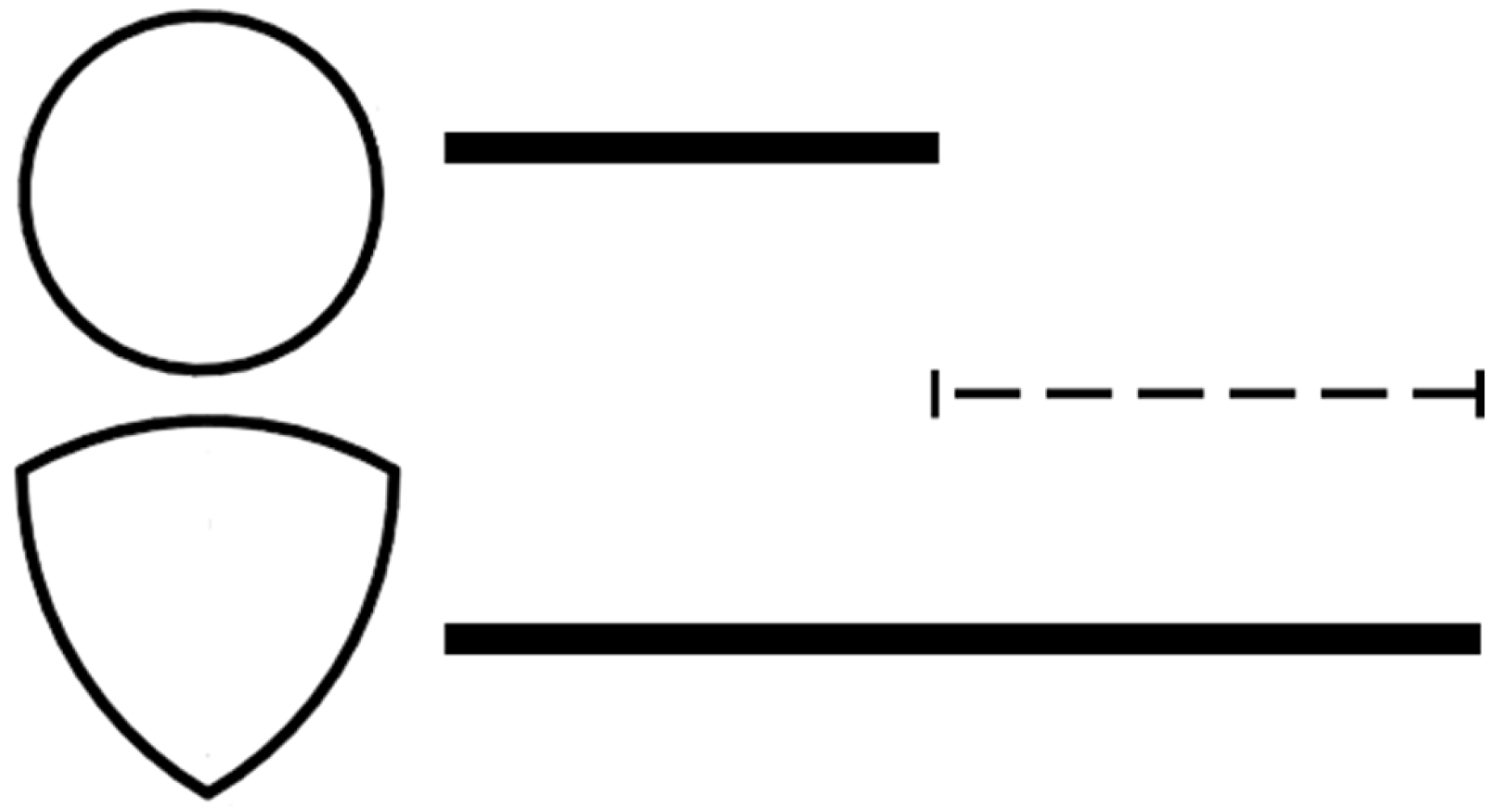
Figure 2.
VRA configuration: longitudinal section; axial flow indicated by a straight arrow.
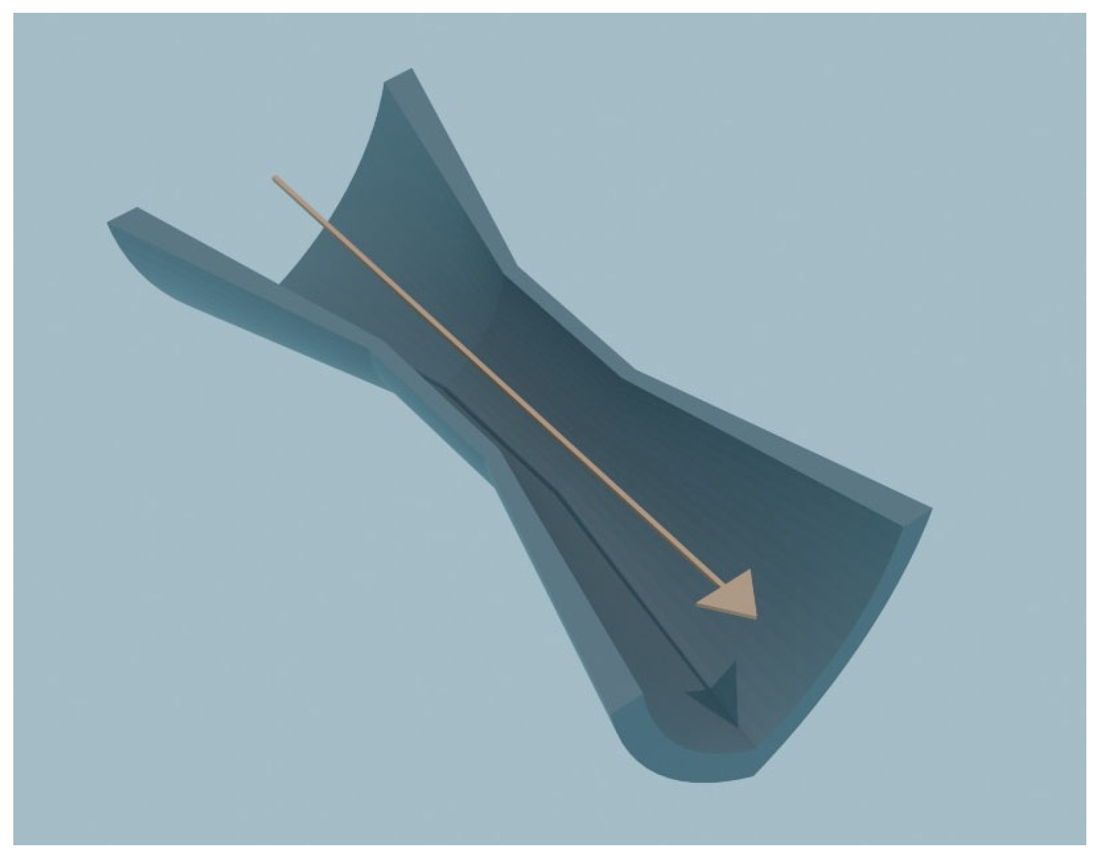
Figure 3.
VRAt configuration: longitudinal section; helical flow (co-rotating swirl) indicated by a ribbon-like arrow; path length longer than in the axial case.
Figure 3.
VRAt configuration: longitudinal section; helical flow (co-rotating swirl) indicated by a ribbon-like arrow; path length longer than in the axial case.
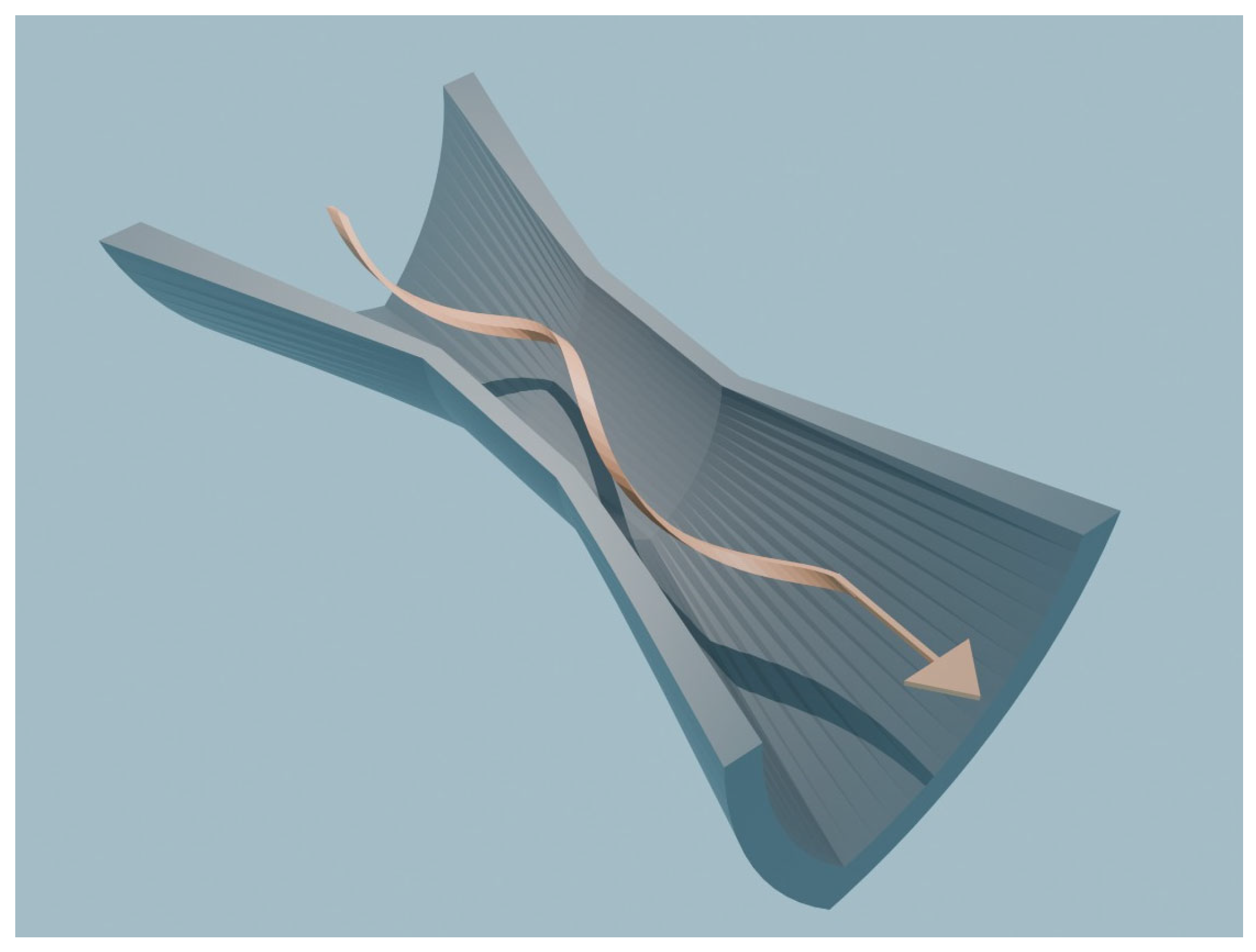
Figure 4.
Cross-sectional distributions of cavitation inception events for iso-area nozzles without swirl. (a) Circular cross-section. Point clouds: gold, events in the bulk; light blue, rare near-wall events; red, uniformity markers located slightly inside the wall. Baseline without swirl. (b) VRA cross-section (Reuleaux triangle, iso-area). Compared with the circular case, both the total event density and the near-wall fraction increase; red markers indicate uniform coverage along the perimeter.
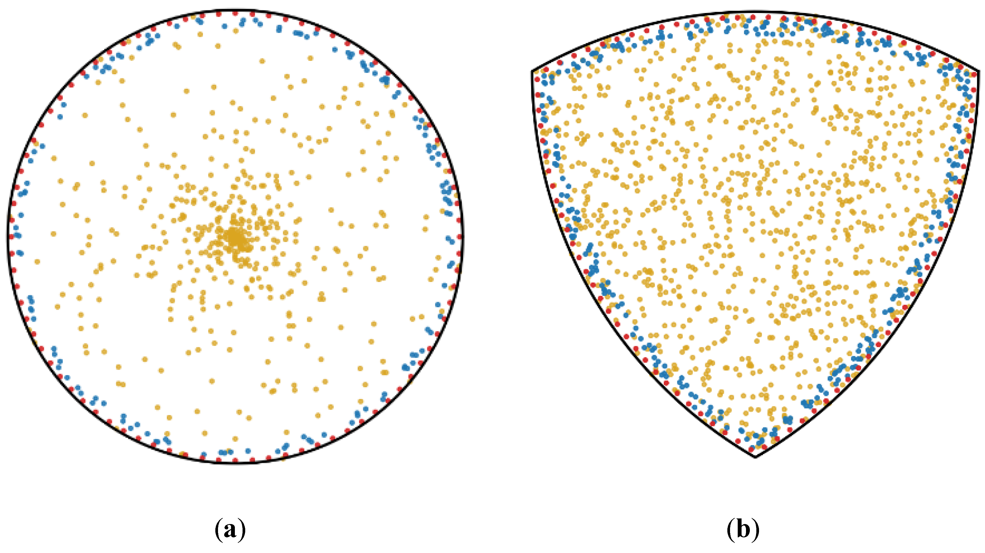
Figure 5.
VRAt configuration (co-rotating swirl). Near-wall swirl: pink markers indicate inceptions originating at the cusps with maximum density and decaying along the arcs; near-wall exposure increases because .
Figure 5.
VRAt configuration (co-rotating swirl). Near-wall swirl: pink markers indicate inceptions originating at the cusps with maximum density and decaying along the arcs; near-wall exposure increases because .
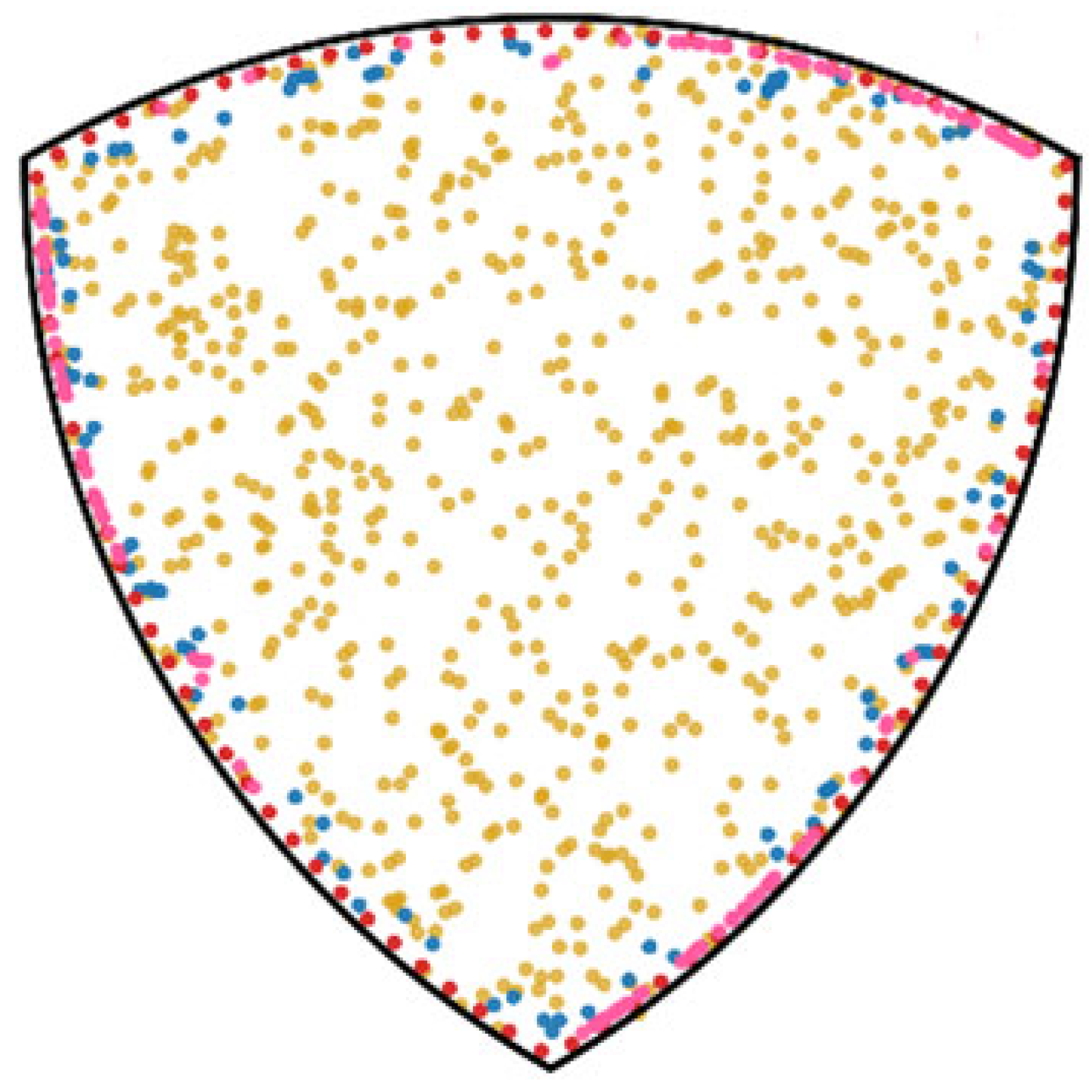

Table 1.
Relative geometric and inception-related metrics for circular, VRA and VRAt configurations.
Table 1.
Relative geometric and inception-related metrics for circular, VRA and VRAt configurations.
| Configuration | ||||
| Circular | = | = | = | |
| VRA | ||||
| VRAt |
Note: All entries are expressed relative to the circular baseline. = equal to circular; greater than circular; much greater; – not applicable; superscript a denotes near wall localization with azimuthal anisotropy, maxima at cusps and decay along arcs. The comparison for χε uses the same and the metric reports the near-wall fraction; localization is conveyed by marker a and by the index . Swirl does not change , therefore is the same in VRA and VRAt, both above the circular reference. In the parameter is held constant; the increase in VRA stems from larger , and the additional increase in VRAt comes from the helical path with and from the swirl-induced pressure fluctuations that favour inception. All values are theoretical and require experimental validation and dedicated simulations.
Disclaimer/Publisher’s Note: The statements, opinions and data contained in all publications are solely those of the individual author(s) and contributor(s) and not of MDPI and/or the editor(s). MDPI and/or the editor(s) disclaim responsibility for any injury to people or property resulting from any ideas, methods, instructions or products referred to in the content. |
© 2025 by the authors. Licensee MDPI, Basel, Switzerland. This article is an open access article distributed under the terms and conditions of the Creative Commons Attribution (CC BY) license (http://creativecommons.org/licenses/by/4.0/).
Copyright: This open access article is published under a Creative Commons CC BY 4.0 license, which permit the free download, distribution, and reuse, provided that the author and preprint are cited in any reuse.


