
Submitted:
16 November 2025
Posted:
17 November 2025
You are already at the latest version
Abstract
In a globalized world where data plays an important role in system operation, process automation, decision-making, etc., the development of real-time control systems is essential because it allows operators or supervisors to know the current status of a process based on the physical variables that are part of it. Therefore, there is currently a wide range of software/hardware tools available through which control systems can be implemented to operate in real time, some of which are Arduino, ESP32, and PIC microcontrollers. As an alternative to the current limitations of the aforementioned systems, this paper presents a novel proposal for the implementation of digital controllers using Texas Instruments embedded systems, which is based on an experimental framework using different test plants for which different control strategies were designed. The results obtained highlight the ability of Texas Instruments microcontrollers to execute real-time control loops applied to different physical systems and operated under different parameters. In conclusion, it was evident that Texas Instruments embedded systems equipped with different microcontrollers are an interesting alternative in the development of control systems, not only on a small scale but also in industrial applications.
Keywords:
C2000 microcontrollers
; Code Composer Studio
; control loops
; Energia
; embedded systems
; real-time control
; Texas Instruments
; Simulink/MATLAB
1. Introduction
As in other fields of knowledge, control engineering has undergone significant advances in recent decades, largely due to the development of sophisticated software and hardware technologies. The most significant changes occurred with the advent of the industrial revolution and the development of the First and Second World Wars. These events demonstrated the need to implement robust control systems with much more rigorous and mathematically correct procedures [1]. In the early days of the Industrial Revolution in Europe, controllers that could not be adjusted manually were developed. This development led J. C. Maxwell to make a significant contribution to the development of control systems by linearizing the differential equations of motion. This allowed him to obtain a characteristic equation of a physical system through which stability parameters could be analyzed [1]. However, it was not until the period between 1892 and 1898 that pioneering work on control based on system stability was conducted, leading to the development of seminal concepts in control theory, including the transfer function [2,3].
The study and evolution of control systems have been marked by different stages. The primitive control stage was from 1868 to 1900. The classical control stage was from 1900 to 1960. The modern control stage has been from 1961 to the present day [1]. The initial stage entailed the formulation of control theory, predicated on the resolution of differential equations that delineated the stability of the systems under investigation. The subsequent stage centered on the examination of methodologies within the frequency domain and the complex plane, predominantly relevant to elementary linear systems. Contemporary control methodologies are predicated on analysis and design theory in the time domain, leveraging state variables across multiple-input, multiple-output (MIMO) systems. The evolution of control systems has also changed the way they are implemented in practice, since previously control loops were implemented analogically, mainly using discrete elements such as resistors, capacitors, inductors, transistors, and operational amplifiers. The accuracy of these systems was compromised because the elements utilized for their implementation were influenced by temporal and thermal fluctuations. These fluctuations were induced by the dissipation of heat [4].
The issue with analog controllers can be addressed by employing digital control systems that utilize digital signal processing to minimize system variation by manipulating characteristics that can affect its operation and accuracy. In contrast, within the domain of digital control systems, it is imperative to acknowledge the pivotal role of arithmetic and word size in determining system accuracy. This is because specific types of arithmetic and word sizes must be considered, as they are directly associated with phenomena such as quantization noise and accumulator overflow. Despite the ability of digital systems to improve the precision of control elements, it is imperative to consider factors associated with the response time of the system, instruction, and energy consumption [4,5]. This is due to the necessity for certain control systems to make decisions in real time, which requires the utilization of embedded or integrated electronics in the implementation of digital controllers.
Control systems have been essential for technological, academic, and industrial advancement, as they allow processes involving physical variables to operate within optimal values and parameters that lead to satisfying the growing demand for products with more detailed characteristics and more efficient performance. Therefore, different sectors of industry and the global economy are opting for compact, low-cost systems for the development of real-time control strategies. These systems have gained relevance due to the wide variety of physical and information processing characteristics with which they are equipped. Although some, such as Arduino, have been developed for general-purpose applications, there are currently others, such as embedded systems based on Texas Instruments (TI) C2000 microcontrollers, which have been developed primarily for the development of real-time control systems. C2000 microcontrollers emerged primarily as an alternative for large-scale industrial control through the inclusion of advanced hardware capabilities and optimization in the execution of instructions for control loops. However, this type of device has now spread to other types of environments, such as academia in technology and engineering programs [6].
The research findings indicate the potential of Texas Instruments’ C2000 microcontrollers in implementing real-time control strategies through various test plants. The design, simulation and validation of the developed controllers were carried out through simulations in different software tools. The research carried out has yielded several other contributions, which are listed below:
- The development of multi-platform control strategies is achieved through the utilization of tools such as Simulink/MATLAB, Code Composer Studio (CCS), and Energia IDE.
- Real-time control strategy validation is to be conducted using industrial prototypes on a laboratory scale within controlled environments.
- The utilization of particular features in the development of control strategies for C2000 microcontrollers is a subject of particular interest. Here, a case study of the Control Law Accelerator (CLA) is presented.
- The present study aims to provide a comprehensive overview of laboratory practices implemented in the Electronic Engineering and Electronic Instrumentation Technology programs at the Universidad del Quindío.
2. Literature Review
Several studies have been conducted on digital controllers, in which various embedded systems have been used for signal processing in control law. These systems have been programmed across multiple platforms using different programming languages, notably C/C++. The integration of these elements is crucial for the development of real-time controllers, utilizing both conventional and advanced control methodologies.
In [7,8], fuzzy logic controllers were developed for pressure control in tanks. In the first, the Takagi–Sugeno model was used and in the second, the Mamdani model. Atmel ATmega8 and AT89C51RC microcontrollers programmed in C language were used as processing systems. [9] presents the implementation of a Linear Quadratic Regulator (LQR) for pendulum position control, using the Rapid Control Prototyping (RCP) technique with MATLAB/Simulink. An Atmel Company ARM AT91SAM9263 processor and a TI F2812DSP DSP were used to develop the real-time control strategy. Other applications of embedded systems are geared towards the development of IoT applications, such as the one carried out in [10], where a PIC 24FJ48G002 microcontroller was used for the design and implementation of a universal board for real-time measurement and control applications. In [11], a real-time integrated control system was designed and implemented for a four-rotor helicopter. The control techniques used were oriented towards the use of nonlinear and linear control strategies, such as the PID controller. The Texas Instruments TMS320F2812 embedded system was used for control signal processing, which was programmed in C language through Code Composer Studio (CCS). Additionally, [12] presents the development of a low-cost system for control engineering education processes through Rapid Control Prototyping (RCP), using low-cost hardware, such as Arduino Uno, through an ATmega328P microcontroller and Simulink/MATLAB for controller design, simulation and hardware implementation. In [13], a wind turbine simulator (WTS) was proposed that uses a 5V DC motor and a DC converter to emulate the real characteristics of wind turbines. A C2000 Delfino TMS320F28335 microcontroller was used to calculate the torque based on the characteristics of the wind turbine and to control the DC drive. The programming for real-time monitoring and parameter adjustment was performed using Code Composer Studio (CCS). [14] proposes a reference framework to implement digital control strategies using Texas Instruments C2000 microcontrollers through the Energia IDE. The experimental framework used Texas Instruments LAUNCHXL-F28379D embedded systems and C language programming to implement different control techniques, such as PID and RST. Other works, such as [15], include developments using the Xilinx Zynq-7000 FPGA, which includes a dual-core ARM Cortex-A9 processor for the implementation of Lipschitz interpolation (LI) algorithms using parallelism techniques for simultaneous data processing. In[16], a methodology for low-cost control design and Hardware-in-the-Loop (HIL) simulation of an interconnected multivariable smart grid is presented. The utilization of a discrete-time linear quadratic regulator (LQR) controller for the real-time multivariable system is proposed, with the implementation of two microcontrollers. Texas Instruments’ C2000 Delfino and the Arduino DUE embedded system are two notable examples of such technologies. Another work utilizing the LAUNCHXL-F28379D evaluation board is presented in [17], which details the integration of Texas Instruments C2000 microcontrollers with MATLAB and Simulink Embedded Coder for real-time control applications. In this study, the BOOSTXL-BUCKCONV BoosterPack DC-DC converter was used to engineer a discrete PI controller. Finally, in [18], a digital control system for biofermentation was designed using an ARM9 S3C2410A microprocessor and embedded Linux. The temperature is regulated by a fuzzy PID control designed in MATLAB.
A survey of the relevant literature reveals the existence of numerous studies that focus on the implementation of real-time digital control systems. However, the use of microcontrollers or embedded systems specifically designed for digital control applications, such as those developed by Texas Instruments, is rarely incorporated. This highlights the contribution of this research to existing literature, which includes the use of TI embedded systems and microcontrollers that integrate specific modules for real-time control, such as the Control Law Accelerator (CLA), into a single application.
3. Methodology
The methodology used in the development of this research was based on an experimental framework for the implementation of digital control strategies using Texas Instruments C2000 microcontrollers. The processing of control signals was facilitated by the LAUNCHXL-F28379D embedded system, which was equipped with a dual-core C2000 Delfino TMS320F28379D microcontroller. The programming of these microcontrollers for the test plants used was carried out through three different platforms: The software in question includes Simulink/MATLAB, Code Composer Studio (CCS) and Energia IDE, with the C/C++ programming languages being used.
3.1. Test Plants
3.1.1. Second Order System
The first prototype used was a second-order under-damped system represented by operational amplifiers, as illustrated in Figure 1.
The system shown in Figure 1 can be mathematically represented in state space according to Equation (1).
By replacing the values shown in the block diagram of Figure 1 in (1), we obtain the equation system shown in (2).
The open-loop response of the system presented in is illustrated in Figure 2. It is evident that the system stabilizes in approximately 60 seconds and exhibits an overshoot of approximately 108.33%.
3.1.2. Flying Cutting Prototype
Flying cutting plants are machines that cut moving parts through a mechanical synchronization process between the blade and the moving material. At the industrial level, there are different types of flying cutting machine, which are defined or classified by manufacturers such as RISHBIN. The latter’s catalog includes machines for cutting metal plates classified as rotary, swivel lever, and pendulum machines [19]. The cutting mechanism is composed of an X and Y coordinate system that generates the movement of the conveyor belt and a servomotor on the Z axis that executes the cutting action. The prototype flying cutting plant is illustrated in Figure 3.
Looking for a mathematical model for the flying cutting plant prototype, an identification process was carried out using the MATLAB System Identification toolbox based on the input signal and the system response. The summary of the identification process is shown in Figure 4, and the mathematical model obtained is presented in .
3.1.3. Level Tank
The level tank used in this study was a 16-liter glass tank equipped with two motor pumps and a potentiometer to measure the level inside. The motor pumps employed in this system are actuated by pulse-width modulation (PWM) signals, and the system as a whole is powered by a 5 VDC power source. The level plant used in the experimental framework of the research is illustrated in Figure 5.
The mathematical model that describes the response of the level plant is shown in (4). This model was obtained in a manner analogous to that employed for the flying cutting plant, using an offline identification process in MATLAB.
After knowing the mathematical model of the level plant, the response of the plant was obtained. The transient response of the level plant demonstrates a characteristic behavior of this type of system, and it can be observed that its response stabilizes after approximately 176 seconds, meeting a criterion of 2% criterion. The transient response of the level plant is demonstrated in Figure 6. Following the determination of the mathematical model of the level plant, its response was obtained. The transient response of the level plant demonstrates a characteristic behavior of this type of system, and it can be observed that its response stabilizes after approximately 176 seconds, meeting a criterion of 2%. The transient response of the level plant is demonstrated in Figure 6.
4. Experimental Design
In the experimental design of the tests and the validation of the digital controllers applied to the test plants described in the previous section, three (3) PID controllers were proposed. These were designed using different tuning methodologies, such as the Ziegler-Nichols rules and the direct tuning of the RCP, using software tools such as MATLAB PID Tuner, CCS and Energia IDE [20,21].
The implementation of Digital PID controllers on the LAUNCHXL-F28379D launchpad incorporated a parallel PID controller configuration, as illustrated in Figure 7. The subsequent section details the procedure for designing the controllers for each of the test plants.
4.1. Second Order System Controller
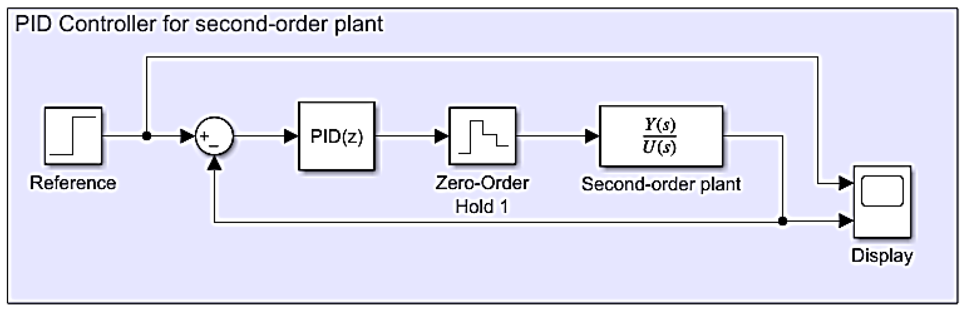
The design of the PID controller for the second-order underdamped plant began with the discretization of its mathematical model, taking a sampling time of seconds. The discrete model for the plant is shown in , and the control loop proposed for the PID control of the plant is shown in Figure 8.
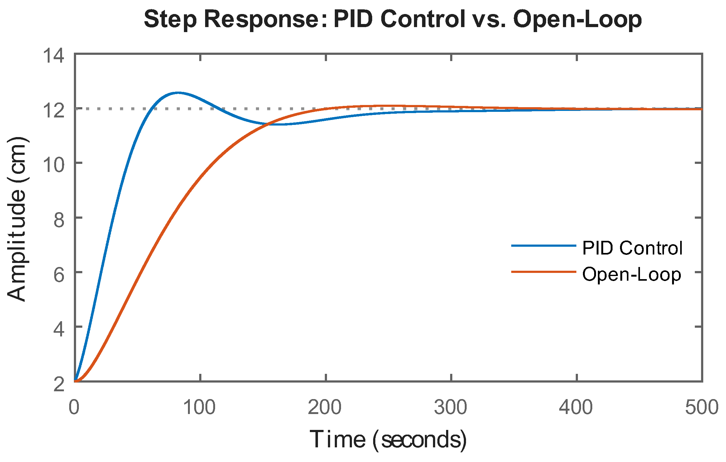
With the control loop defined in Figure 8, the controller was tuned in MATLAB PID Tuner. For this controller, a overshoot was defined as a characteristic, regardless of the time it will take to stabilize. After the tuning process, the closed-loop response shown in Figure 9 was obtained with constants , , and .
With the values of the constants , , and for the PID controller, we proceeded to obtain its difference equation so that it could be implemented through the C2000 microcontroller on the LAUNCHXL-F28379D development board. Finally, the discrete transfer function for the PID controller is as follows:
Substituting the values of , , and into we obtain the following:
Applying the inverse Z transform to we obtain the difference equation for the PID controller as shown in (8).
Finally, is the equation that will be used in the results section for the implementation of the digital PID controller. As mentioned earlier, the PID controller has different structures and tuning methods. For this research, was obtained from the proposal in [23].
4.2. Flying Cutting Plant Controller
For the design of the flying cutting plant controller, a PI structure was chosen due to the characteristics of the plant, it was not necessary to implement derivative action. The PI controller for the plant described in was tuned through MATLAB PID Tuner using the control loop shown in Figure 10, resulting in the and constant values shown in Figure 11.
By simulating the controller obtained with MATLAB PID Tuner, the control effort signal is small, and the controller follows the reference properly. The responses of the PI controller and the control effort are shown in Figure 12.
To implement the system described above digitally, the sampling time must be calculated considering the behavior of the poles in open loop and closed loop. The procedure for calculating the poles and sampling time is shown below.
The poles of the open-loop system taken from the system shown in Figure 10 are defined by:
Then, the poles of the closed-loop system are described by:
By solving , we obtained the following closed-loop poles:
To find the maximum frequency of the system, the magnitude of the poles obtained was calculated, resulting in . This result allowed the sampling time of the system to be calculated as shown below.
For the development of the established experimental framework, a Tm=0.1 seconds was chosen for the reading of the encoder and the execution of the control strategy. Additionally, to implement the PI controller through the C2000 microcontroller and the LAUNCHXL-F28379D launchpad, its equation was discretized using the rectangular approximation method, as shown in Table 1.
The equivalent discrete-time PI controller and its difference equation for digital implementation were calculated from the structure of the continuous-time parallel PID controller as shown in equations and .
Remember that the PID controller constants can be expressed in terms of the error signal as:
From , proportional action was defined as:
Applying the inverse Z transform to , we obtain the difference equation for the proportional action:
From , the integral action was defined as:
Applying the inverse Z transform to , we obtain the difference equation for the integral action:
From , the derivative action was defined as:
Applying the inverse Z transform to , we obtain the difference equation for the derivative action:
Finally, the equation of the discrete PID controller for the flying cutting plant is presented in .
It is important to remember that the flying cutting plane will have a PI controller, so the derivative action is equal to zero; therefore, can be rewritten as:
4.3. Level Tank Plant Controller
The PID controller for the level plant was designed so that the plant would respond quickly to reference changes. In addition, the behavior of the PID controller had to ensure a maximum overshoot of , since any value above the reference could cause the plant level to overflow. Unlike previously designed controllers, the control loop for the level plant was designed using the two CPUs equipped in the C2000 microcontroller of the LAUNCHXL-F28379D launchpad (CPU1: PID controller and CPU2: level plant), and the PID controller was developed using the Control Law Accelerator module (CLA) module. The block diagram of the PID controller for the level plant is shown in Figure 13.
Similarly to the design of the previous controllers, the PID controller for the level tank used a parallel structure and was tuned using MATLAB PID Tuner, employing the discrete model for the plant and considering sampling time of seconds. The mathematical model for the PID controller used is presented in and for continuous time and discrete time, respectively. With values of , , and , the response of the controlled system is shown in Figure 14.
Figure 14.
Closed-loop PID controller response for the level plant. Source: The authors.
The discrete representation of the PID controller shown in (27) did not get its corresponding difference equation because the implementation of this real-time control strategy was carried out using the embedded code generator in Simulink/MATLAB.
5. Results
This section presents the results of the simulation and implementation of digital controllers in different test plants. The validation of the experimental framework of the research was divided into two stages: the first focused on the simulation of the discrete models of the test plants and the controllers tuned with MATLAB PID Tuner through the control loops shown in Figure 8, Figure 10 and Figure 13. Subsequently, the digital implementation of the controllers with the actual plants and the C2000 microcontroller was carried out using the Energia IDE, Code Composer Studio and Simulink/MATLAB tools.
5.1. Implementation of Digital Controller in the Second-Order System
The simulation of the PID controller for the second-order plant was carried out in Simulink/MATLAB based on the control loop proposed in Figure 8. Currently, there are different ways to simulate systems in Simulink/MATLAB (transfer function, differential equation, etc.), and the choice of one or the other depends on the purpose of its use. Figure 14 shows one of the implementation possibilities considering a sampling time of 0.5 seconds, as mentioned in the previous section.
Figure 14.
Block diagram for the PID controller in the second-order plant. Source: The authors.
The response of the control loop shown in Figure 14 is observed in Figure 15. There, the controller exhibits an appropriate response with respect to the design parameters, with overshoot and a slightly shorter settling time. Subsequently, the digital PID controller was implemented in C2000 microcontroller on the LAUNCHXL-F28379D embedded system using Energia IDE. This platform allows different microcontrollers (including some from TI) to be programmed in C/C++ language in a similar way to Arduino [24]. The graphical interface of the Energia IDE is shown in Figure 16.
The PID controller was implemented in the C2000 microcontroller using the C language (the defined functions and their content are presented in Appendix A) as shown in Figure 17. To validate the operation of the PID controller in the second-order plant built using operational amplifiers and an ATX power supply, the control loop shown in Figure 18 was implemented. Finally, to validate the operation of the PID controller in real time, a DAQ NI 6002 data acquisition card was used to visualize the plant response in MATLAB [25].
5.2. Implementation of Digital Controller in the Flying Cutting System
The simulation and implementation of the PI controller for the flying cutting plant were carried out with consideration for the control loop shown in Figure 10. To validate the controller’s response at the simulation level, the block diagram shown in Figure 20 was implemented in Simulink/MATLAB, where the discrete PI controller and the flying cutting plant model were observed.
The simulation of the PI controller for the control loop shown in Figure 20 presented a response in line with the design conditions mentioned in the previous section, highlighting the ability of the MATLAB PID Tuner to tune controllers directly. Figure 21 shows the responses of the closed-loop PI controller and the open-loop plant.
Once it was verified that the controller responded appropriately, the digital controller was implemented in the TI C2000 microcontroller. In this case, Code Composer Studio (CCS) was used, TI-developed software for programming its microcontrollers, including the C2000 family of devices, ensuring full support for the physical characteristics of embedded systems. CCS allows for the programming and compilation of code developed in the C/C++ language. The CCS IDE is shown in Figure 22.
The PI controller programming was implemented using functions that controlled the plant’s operation. The functionality of these systems, in combination with the controller’s discrete equations, facilitates the execution of adjustments pertaining to movement speed, direction, operating limits, and other parameters. As illustrated in Figure 23, a comprehensive overview of the functions employed for the control of the cutting system of the flying sawmill is provided.
To validate the real performance of the PI controller in the flying cutting plant, the control loop shown in Figure 20 was implemented as shown in Figure 24. In this implementation, the LAUNCHXL-F28379D embedded system, motor control power circuits, signal activation logic comparators and a power source with characteristics like those used in the second-order plant were used to ensure proper operation of the flying cutting plant shown in Figure 25.
Finally, the validation and performance tests carried out generated the results shown in Figure 26. The system starts after 6.8 seconds and takes 1.8 seconds to stabilize at approximately 6330 rpm (blue signal in the upper figure). Once the X-axis detects a variation in the set point, it produces a control effort (blue signal in the lower figure), causing the gear motor to start its process (red signal). The cut is made between 8 and 9.7 seconds when the speeds of the belt and the X-axis are equal.
5.3. Implementation of Digital Controller in the Level Plant
The control loop shown in Figure 13 for the level plant was implemented by configuring the CLA and the two CPUs of the C2000 microcontroller. For the experimental and validation framework of this research, the PID controller was run on CPU1, while the information from the actuators and sensors of the physical plant was processed on CPU2. Once the performance of the CPUs had been defined, the different configurations of the CLA modules were carried out to ensure the parallel execution of tasks within the microcontroller. The control algorithms were encapsulated using the CLA Subsystem block and triggered by the C28x CLA Task. Figure 27 and Figure 28 show the control structure for the level plant using the two CPUs available in the microcontroller.
Figure 27 shows the implementation of the parallel PID controller designed in the previous section. The error signal for the controller is obtained by subtracting the INT_CLA1 (reference) and INT_CLA2 (feedback) signals, and after the control signal (OUT_CLA) is processed, it is connected to the plant input (INT_CLA1) in Figure 28, and when the new output value (OUT_CLA) is updated in the same figure, it is connected to the controller to update the error signal. The necessary configurations for the implementation of the system were then made, as shown in Figure 29, and the Simulink/MATLAB-integrated code generator was used to program the LAUNCHXL-F28379D launchpad and validate the operation of the PID controller for the level plant in real time.
The performance achieved for the level plant and the real-time PID controller is shown in Figure 30. The controller responds appropriately to reference changes, showing a response without overshoot and with a shorter settling time compared to the simulated system. This is a feature of modules such as the CLA with which TI’s C2000 microcontrollers are equipped, as they allow parallel execution of the control law and processing of signals from the plant.
6. Conclusions
While Texas Instruments C2000 microcontrollers are primarily designed for real-time control applications in both academic and industrial settings, it is equally crucial to comprehend the characteristics and dynamics of the controlled plant. A robust processing system is essential for executing a control loop effectively, but factors such as overshoot and settling time must also be considered. Some systems are inherently slow and need powerful control actions to reach a desired state without causing saturation.
Integrating C2000 microcontrollers, like the one found in the LAUNCHXL-F28379D launchpad, into the Energia IDE enhances the development of real-time applications. This is because programming is done at a relatively high abstraction level, which eliminates the need for direct knowledge of the operational mode and configuration of each microcontroller register. This is a significant difference from the Code Composer Studio (CCS) IDE. Furthermore, due to its LGPL licensing, it permits the future creation of additional libraries that can ensure complete integration of the LAUNCHXL-F28379D board into the Energia IDE, along with the potential integration of other unsupported devices.
Control strategies and programming algorithms have been developed to incorporate all essential components typical of large-scale automatic control systems. The utilization of specialized features, such as the Control Law Accelerator (CLA) within the C2000 microcontrollers, presents new possibilities for the GAMA Research Group to enhance the laboratory practices of the Ingeniería Electrónica and Tecnología en Instrumentación Electrónica programs at the Universidad del Quindío. This initiative aims to familiarize future engineers with real industrial processes in controlled settings.
The development of this research enabled the design and implementation of multi-platform control strategies using different tools (Simulink/MATLAB, Code Composer Studio (CCS), and Energia IDE) in conjunction with integrated simulated systems and industrial prototypes on a laboratory scale. This experimental research shows the advantages offered by MATLAB through model-based design, as it allows not only the modeling of a dynamic system but also the use of these designs for real applications through embedded systems using the embedded code generator, which does not require advanced knowledge of the different programming languages used. The different platforms used allow for the development of real-time controllers with appropriate performance; however, each of them has limitations when more robust control strategies are required through specific characteristics of the microcontrollers.
Author Contributions
Conceptualization, DF.R-J, CM.G-A and PA.M-G.; methodology, DF.R-J, CM.G-A and PA.M-G; software, DF.R-J, CM.G-A and PA.M-G.; validation, DF.R-J, CM.G-A and PA.M-G.; formal analysis, DF.R-J, CM.G-A and PA.M-G.; investigation, DF.R-J, CM.G-A and PA.M-G.; resources, DF.R-J, CM.G-A and PA.M-G.; data curation, DF.R-J, CM.G-A and PA.M-G.; writing—original draft preparation, DF.R-J, CM.G-A and PA.M-G.; writing—review and editing, DF.R-J, CM.G-A and PA.M-G.; visualization, DF.R-J, CM.G-A and PA.M-G.; supervision DF.R-J, CM.G-A and PA.M-G.; project administration, DF.R-J, CM.G-A and PA.M-G.; funding acquisition, DF.R-J, CM.G-A and PA.M-G. All authors have read and agreed to the published version of the manuscript.
Funding
This work was supported by Universidad del Quindío (100016837).
Data Availability Statement
Data is contained within the article.
Conflicts of Interest
The authors declare no conflicts of interest.
Appendix A
The files for carrying out the simulations can be downloaded from https://drive.google.com/file/d/1bi2uVoh8wn345mzKm2ZXJE64RXC0IjqR/view?usp=sharing.
References
- I. A. García, Teoría de Estabilidad y Control. Lérida, España: Edicions de la Universitat de Lleida, 2005.
- K. Ogata, Ingeniería de control moderna, 5a. ed. Madrid: Pearson Educación, 2010.
- R. C. Dorf and R. H. Bishop, Modern control systems, Thirteenth edition. Hoboken: Pearson, 2016.
- R. Leach, “Digital control for embedded applications,” in Southcon/96 Conference Record, Orlando, FL, USA: IEEE, 1996, pp. 18–22. [CrossRef]
- M. Moallem, “Design and implementation of computer control software: a low cost laboratory setup,” IEEE Control Syst., vol. 25, no. 1, pp. 26–29, Feb. 2005. [CrossRef]
- D. F. Ramírez-Jiménez and C. A. Torres Valencia, “Experimental Design and Simulation of a Fly-Cutting Plant for Academic Environment Practices,” Machines, vol. 13, no. 1, p. 15, Dec. 2024. [CrossRef]
- S. Srivastava, V. Sukumar, P. S. Bhasin, and D. Arun Kumar, “A Laboratory Testbed for Embedded Fuzzy Control,” IEEE Trans. Educ., vol. 54, no. 1, pp. 14–23, Feb. 2011. [CrossRef]
- N. Kanagaraj and P. Sivashanmugam, “An Embedded Fuzzy Controller for Real Time Pressure Control,” in 2006 IEEE International Conference on Industrial Technology, Mumbai, India: IEEE, 2006, pp. 2023–2027. [CrossRef]
- Z. Fang and Y. Fu, “A networked embedded real-time controller for complex control systems,” in 2011 Chinese Control and Decision Conference (CCDC), Mianyang, China: IEEE, May 2011, pp. 3210–3215. [CrossRef]
- S. Nuratch, “A universal microcontroller circuit and firmware design and implementation for IoT-based realtime measurement and control applications,” in 2017 International Electrical Engineering Congress (iEECON), Pattaya, Thailand: IEEE, Mar. 2017, pp. 1–4. [CrossRef]
- X. Liu, X. Zhao, H. Gu, and A. Sanchez, “Application and Design of Real-Time Control System for the Quad-rotor Helicopter,” in 2009 International Conference on Measuring Technology and Mechatronics Automation, Zhangjiajie, Hunan, China: IEEE, 2009, pp. 40–44. [CrossRef]
- W. Werth, L. Faller, H. Liechtenecker, and C. Ungermanns, “Low Cost Rapid Control Prototyping – a useful method in Control Engineering Education,” in 2020 43rd International Convention on Information, Communication and Electronic Technology (MIPRO), Opatija, Croatia: IEEE, Sept. 2020, pp. 711–715. [CrossRef]
- N. Thodsaporn and V. Kinnares, “Wind Turbine Simulator Equipped with Real-Time Monitoring and User-Friendly Parameter Setup Controlled by C2000 Microcontroller,” in 2020 17th International Conference on Electrical Engineering/Electronics, Computer, Telecommunications and Information Technology (ECTI-CON), Phuket, Thailand: IEEE, June 2020, pp. 713–716. [CrossRef]
- D. F. Ramirez-Jimenez, A. L. Parrado, and J. V. Medina, “Overview of a framework for Implementation of digital controllers in Energia IDE using Texas Instruments microcontrollers,” in 2021 IEEE 5th Colombian Conference on Automatic Control (CCAC), Ibague, Colombia: IEEE, Oct. 2021, pp. 13–18. [CrossRef]
- J. M. Nadales, J. M. Manzano, A. Barriga, and D. Limon, “Efficient FPGA Parallelization of Lipschitz Interpolation for Real-Time Decision-Making,” IEEE Trans. Contr. Syst. Technol., vol. 30, no. 5, pp. 2163–2175, Sept. 2022. [CrossRef]
- Y. Martinez-Armero, S. Lopez-Blandon, and E. Giraldo, “Optimal Control and Low-cost HIL Simulation of a Multivariable Interconnected Smartgrid,” in 2023 IEEE 6th Colombian Conference on Automatic Control (CCAC), Popayan, Colombia: IEEE, Oct. 2023, pp. 1–6. [CrossRef]
- M. A. Rahman, A. A. Abushaiba, and A. M. Elrajoubi, “Integration of C2000 Microcontrollers with MATLAB Simulink Embedded Coder: A Real-Time Control Application,” in 2024 7th International Conference on Electrical Engineering and Green Energy (CEEGE), Los Angeles, CA, USA: IEEE, June 2024, pp. 131–136. [CrossRef]
- S. Xuelei, “The Design of Digital Control System for Bio-fermentation Process Based on Embedded ARM9,” in 2025 IEEE 8th Advanced Information Technology, Electronic and Automation Control Conference (IAEAC), Guiyang, China: IEEE, Aug. 2025, pp. 389–393. [CrossRef]
- “Productos,” RISHBIN WUXI CO., LTD. Accessed: July 05, 2024. [Online]. Available: http://es.rishbin.com.
- B. C. Kuo, Sistemas de control automático, 1. ed. México: Prentice Hall Hispanoamericana, 1996.
- D. F. Ramírez-Jiménez, “Proposal of a Flying-Cutting Plant for the Development of Control Systems in Academic Environments,” Ciencia e Ingeniería Neogranadina, vol. 35, no. 1, pp. 87–112, 2025. [CrossRef]
- E. M. Shaban, H. Sayed, and A. Abdelhamid, “A novel discrete PID+ controller applied to higher order/time delayed nonlinear systems with practical implementation,” Int. J. Dynam. Control, vol. 7, no. 3, pp. 888–900, Sept. 2019. [CrossRef]
- K. Ogata, Discrete-Time Control Systems, 2nd ed. India: Pearson Education (India), 2015.
- I. Bennia, L. Baghli, E. Jamshidpour, A. Mechernene, J.-P. Martin, and D. Yousfi, “Real-Time Power electronics Control and Monitoring with TI F28379D DSC and GUI Composer,” 2025, arXiv. [CrossRef]
- M. Hasman, M. Phung, Z. Feng, and J. Jatskevich, “Microcontroller Implementation of Lookup-Tablebased Hall Sensor Correction for Improving Dynamic Performance for Brushless DC Motors,” in 2025 7th Global Power, Energy and Communication Conference (GPECOM), Bochum, Germany: IEEE, June 2025, pp. 300–305. [CrossRef]
Figure 1.
The block diagram for the under-damped system. Source: The authors.
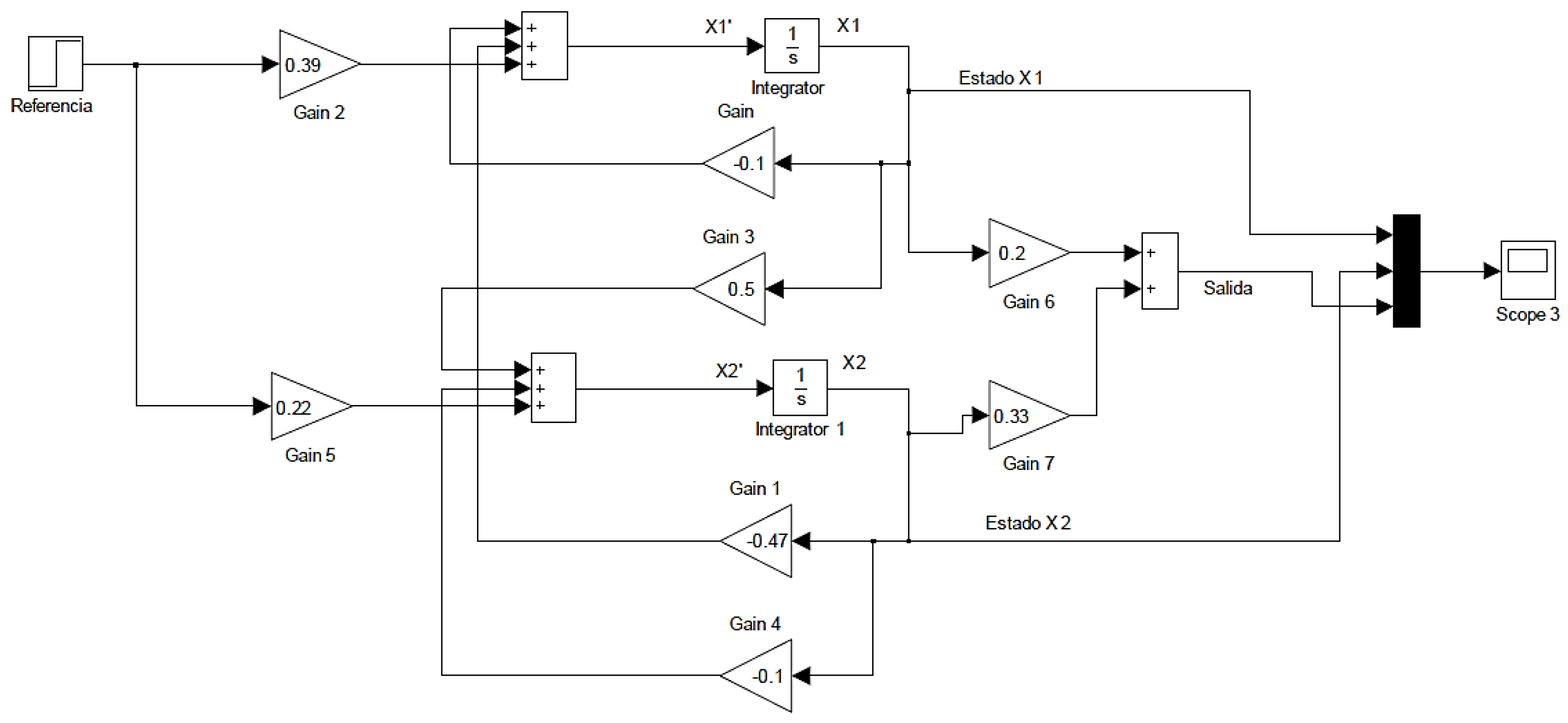
Figure 2.
Transient response of the second-order system presented in . Source: The authors.
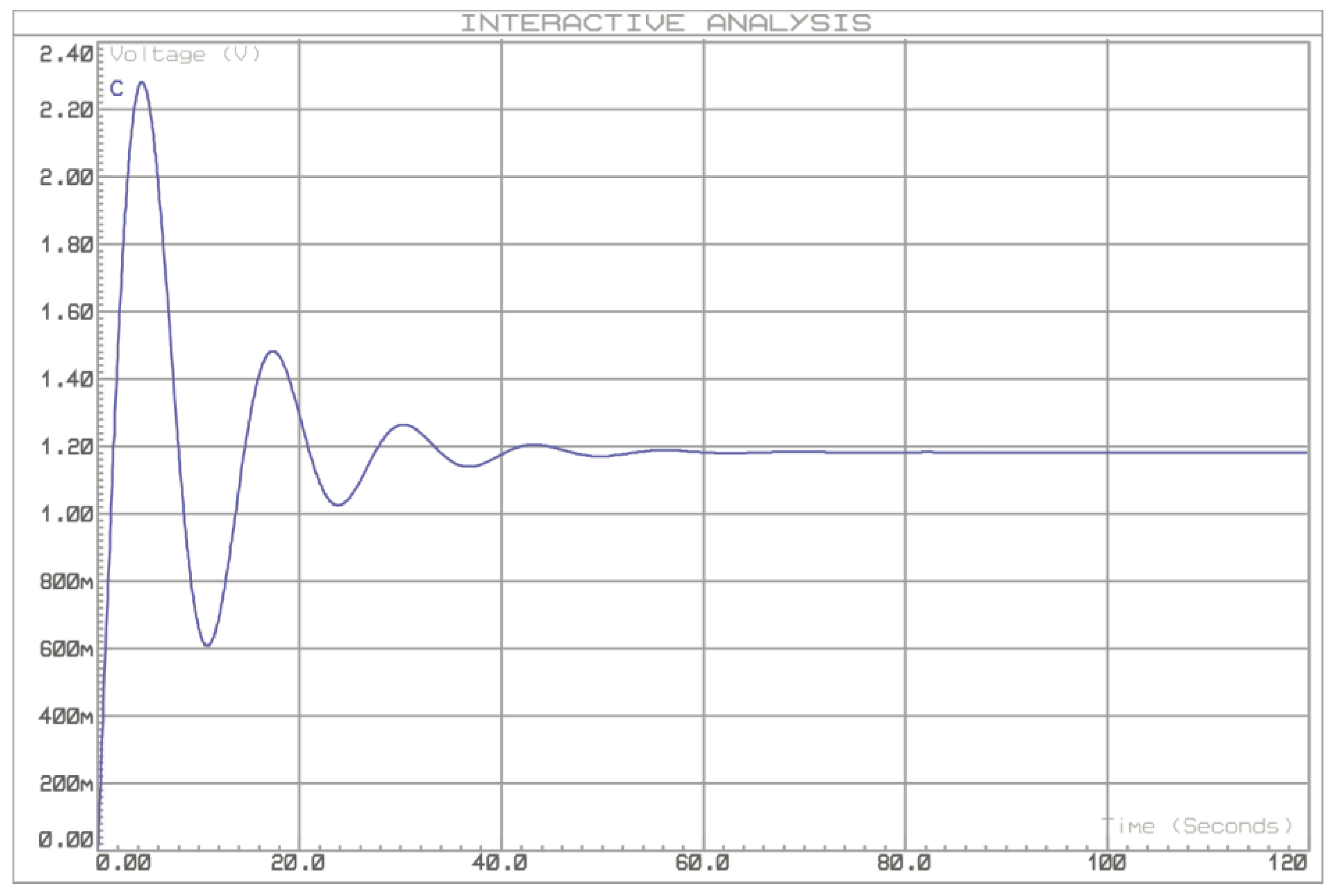
Figure 3.
Prototype of a flying cutting plant. Source: The authors.
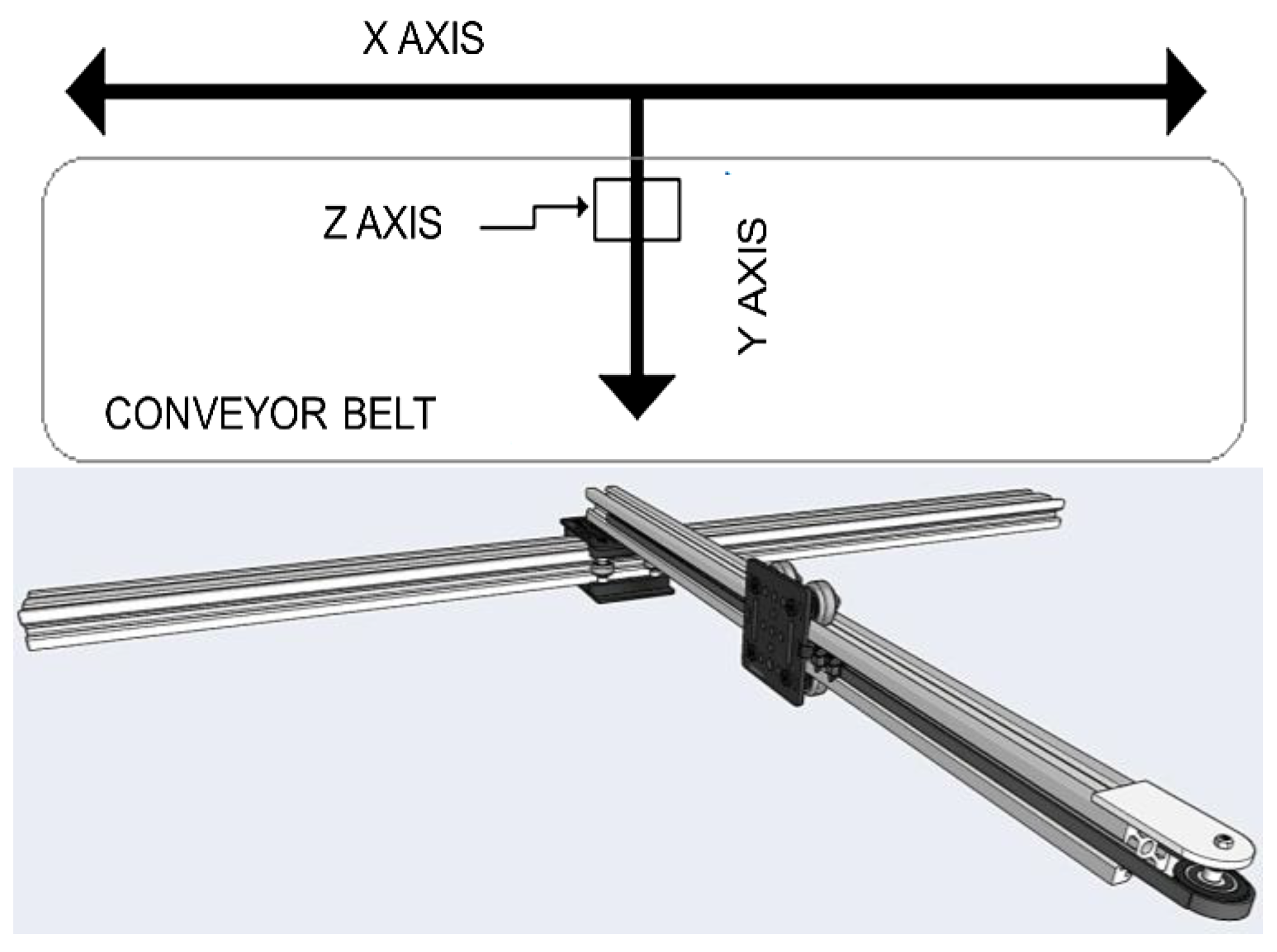
Figure 4.
Identification response for flying cutting plant. Source: The authors.
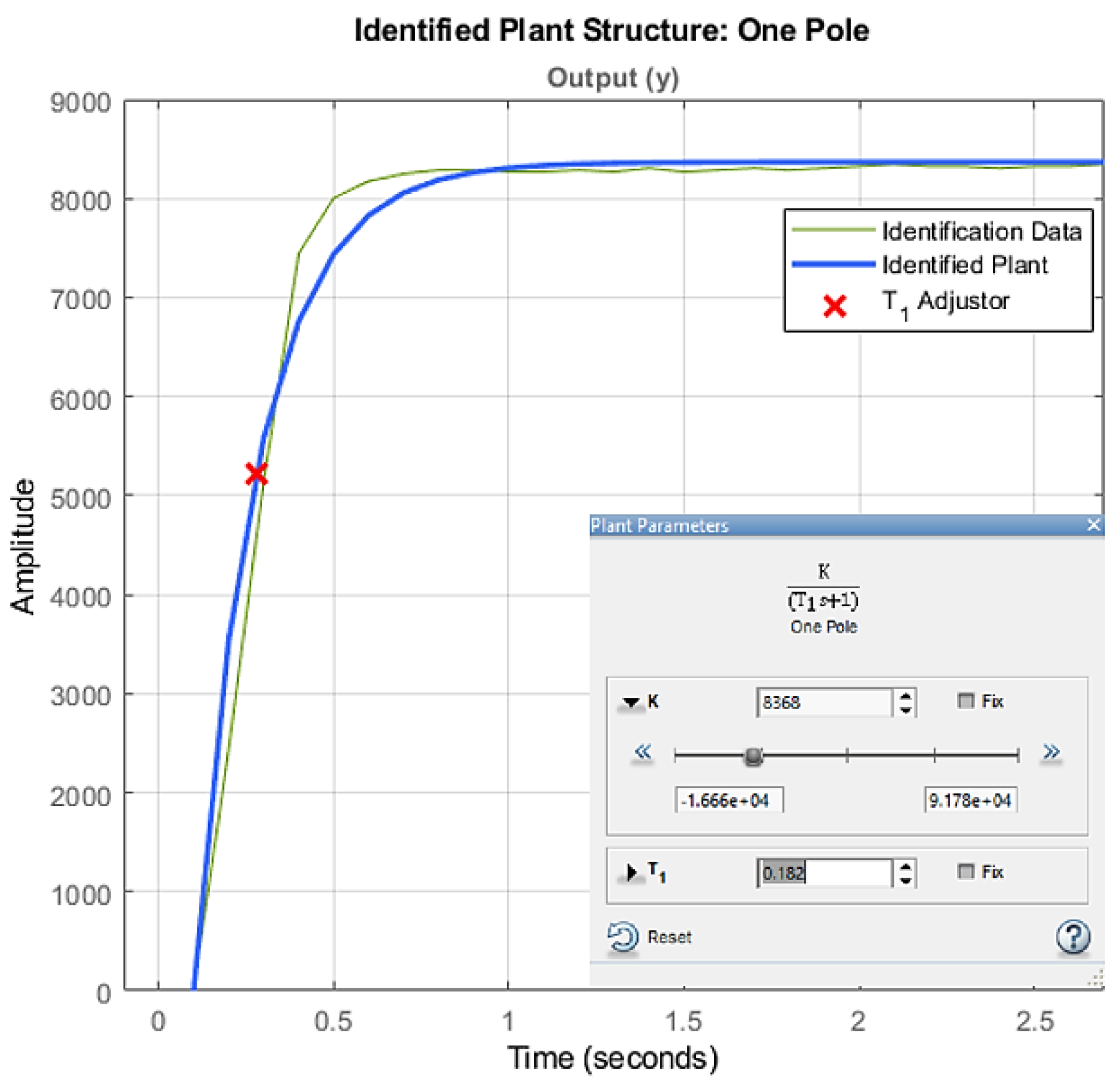
Figure 5.
Front view of the level plant used. Source: The authors.
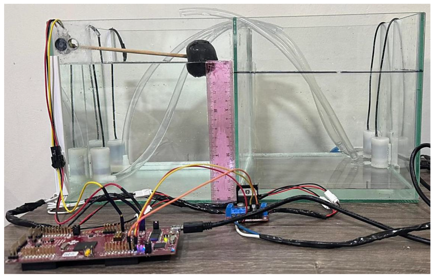
Figure 6.
Transient response for the level plant described mathematically in (4). Source: The authors.
Figure 6.
Transient response for the level plant described mathematically in (4). Source: The authors.
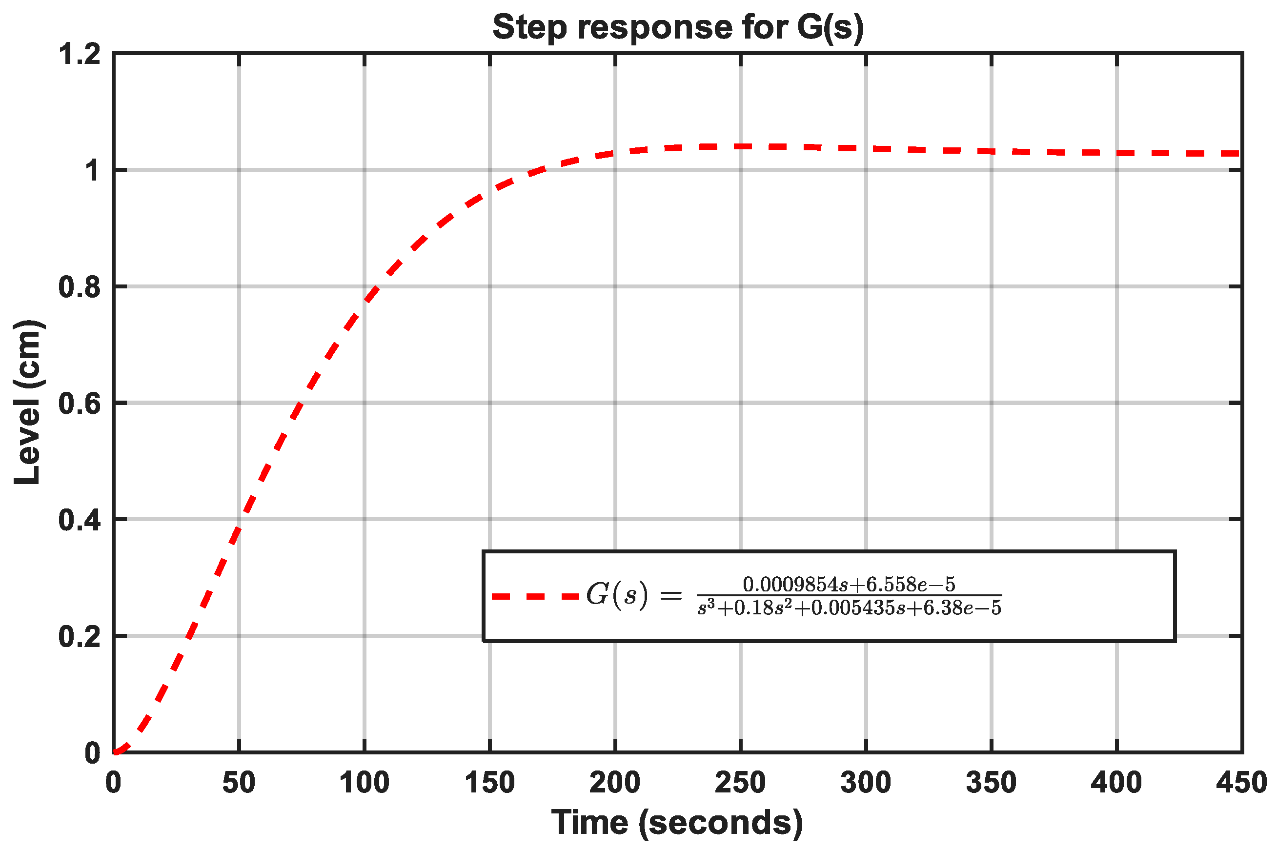
Figure 7.
Discrete PID controller structure in parallel configuration. Source: Adapted from [22].
Figure 7.
Discrete PID controller structure in parallel configuration. Source: Adapted from [22].
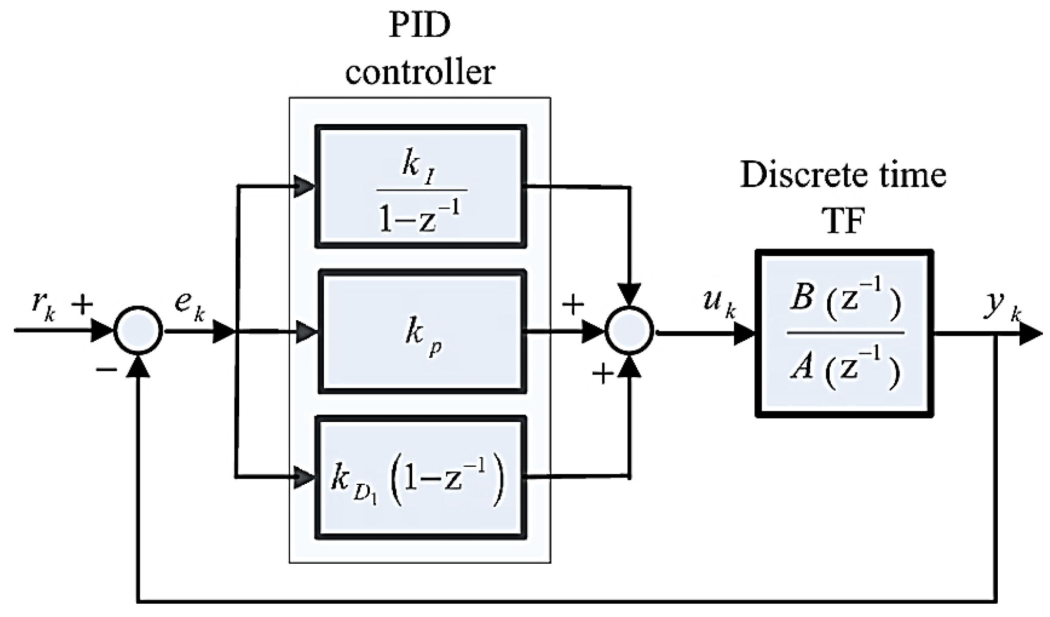
Figure 8.
Proposed control loop for the second-order plant. Source: The authors.
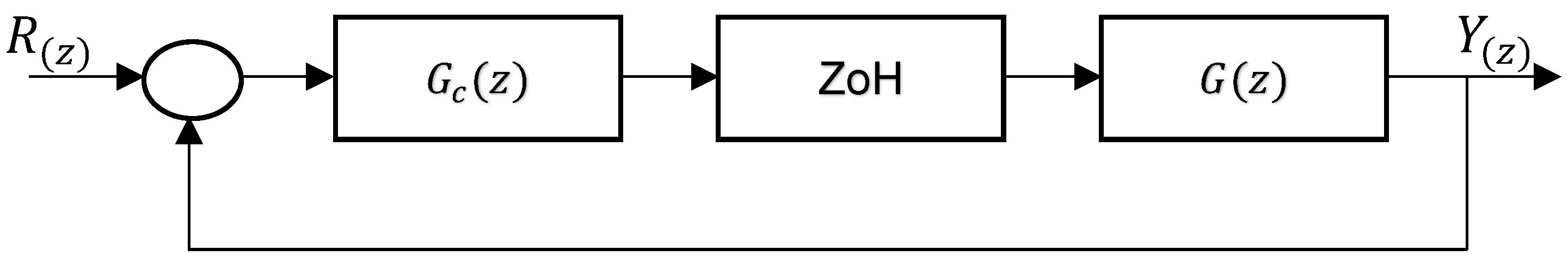
Figure 9.
Response of the PID controller in the second-order plant. Source: The authors.
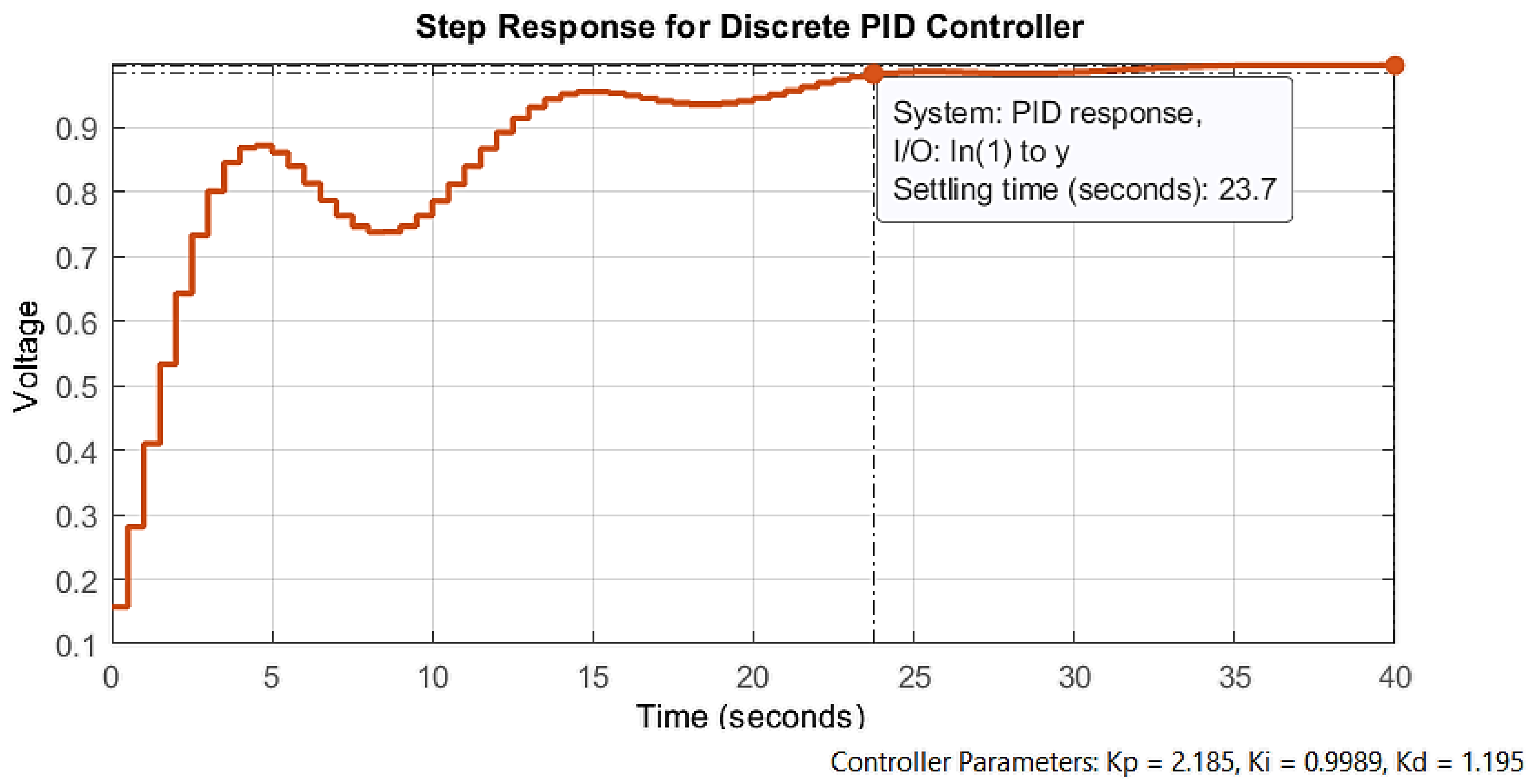
Figure 10.
Proposed control loop for the flying cutting plant. Source: The authors.
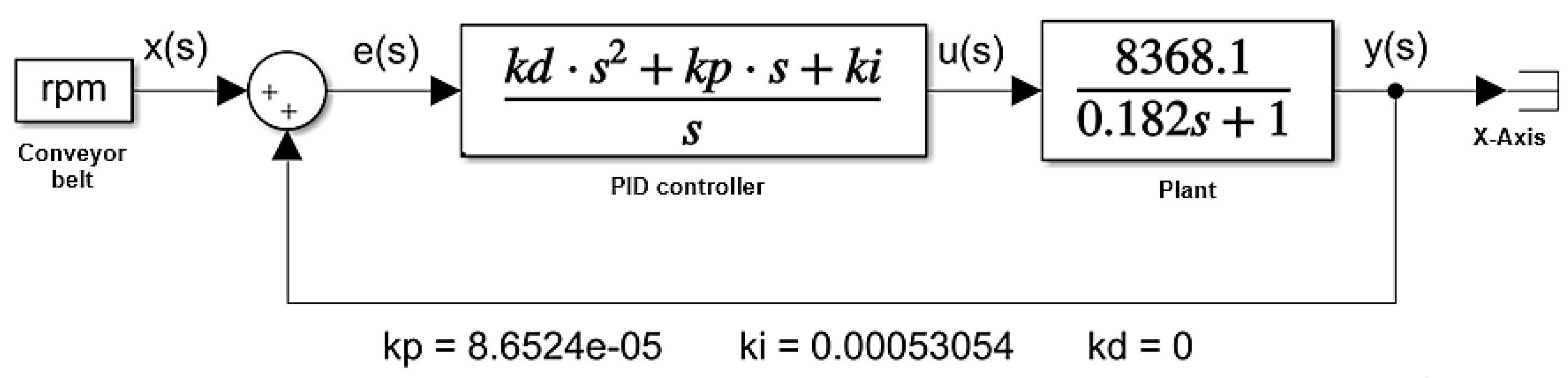
Figure 11.
and constants obtained with MATLAB PID Tuner. Source: The authors.
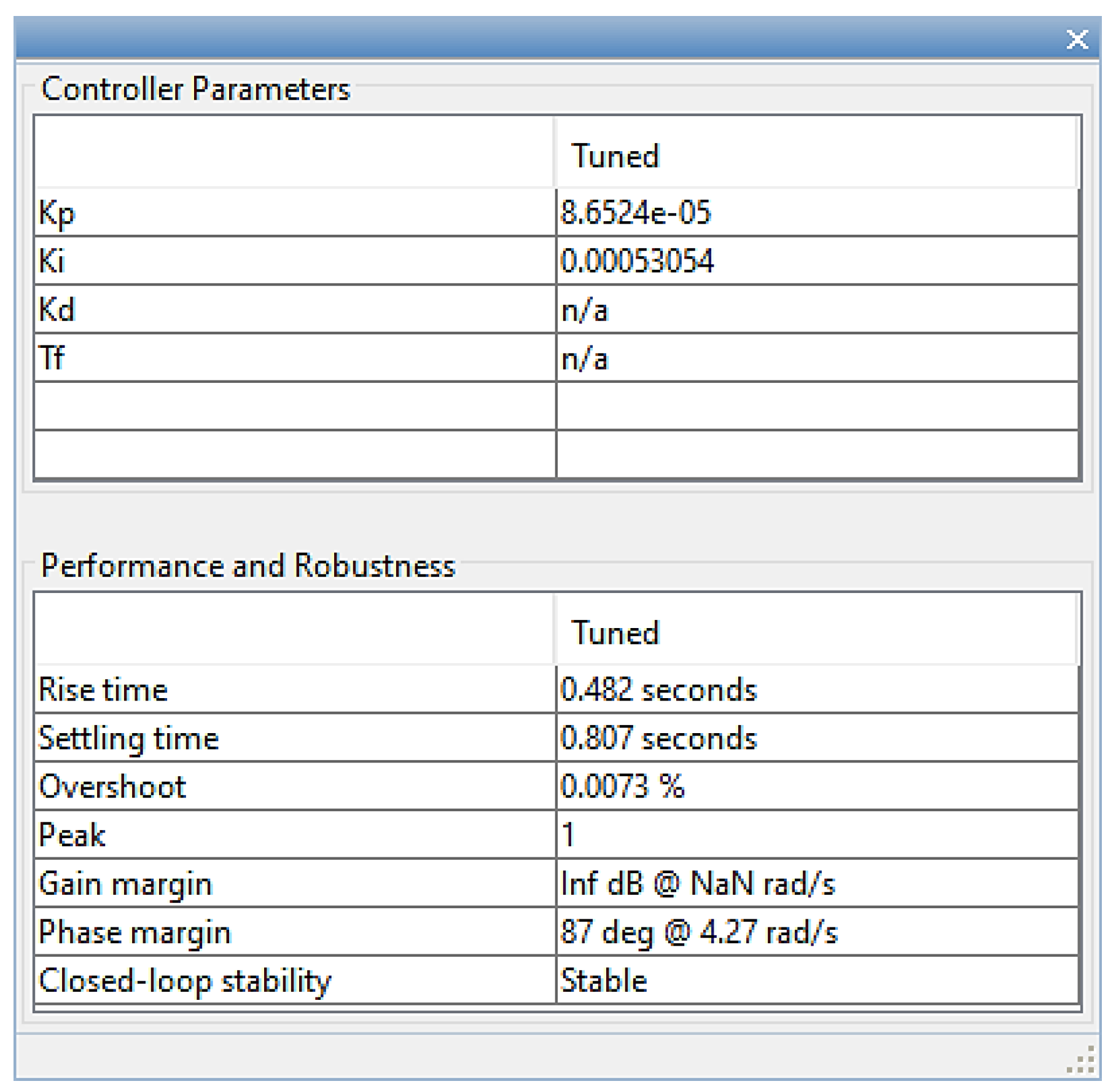
Figure 12.
Normalized response for closed-loop PI controller and control effort in flying cutting plant. Source: The authors.
Figure 12.
Normalized response for closed-loop PI controller and control effort in flying cutting plant. Source: The authors.
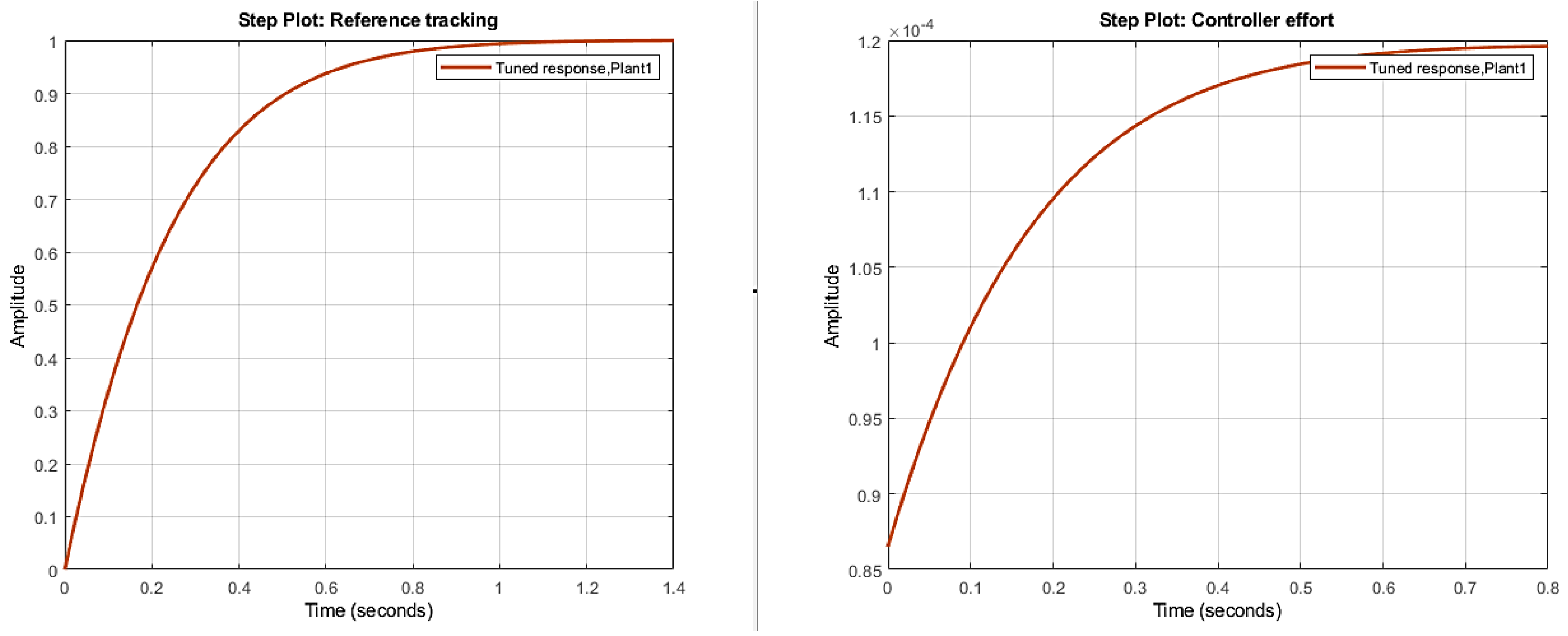
Figure 13.
Proposed control loop for the level plant. Source: The authors.
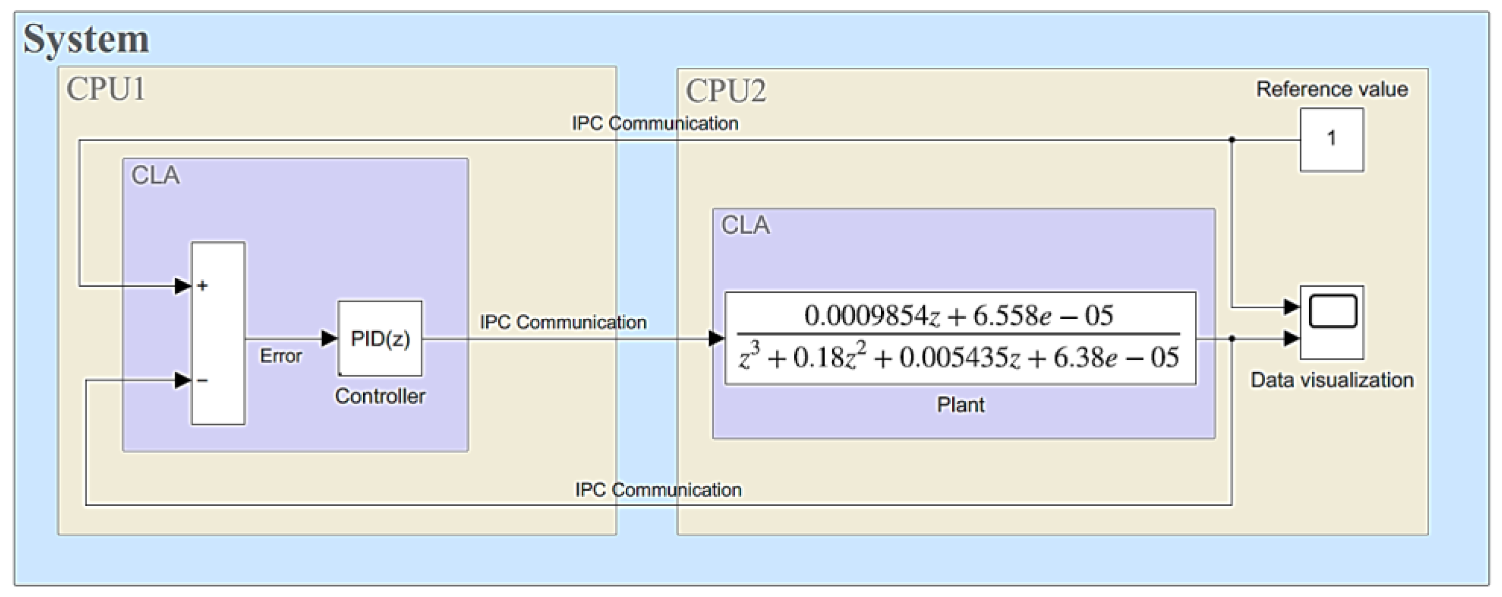
Figure 15.
Simulated PID controller response for the second-order plant. Source: The authors.
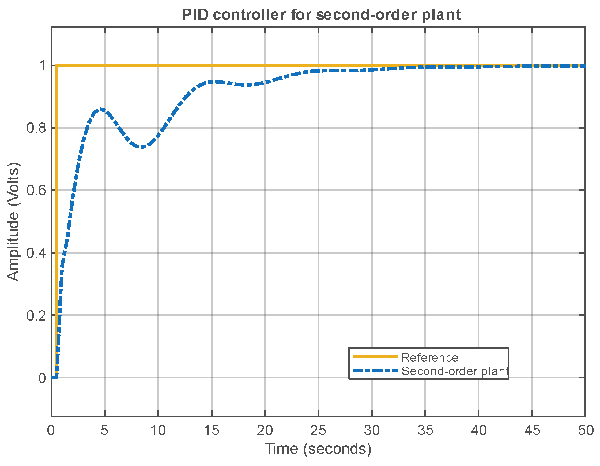
Figure 16.
Energia IDE Graphical User Interface (GUI). Source: The authors.
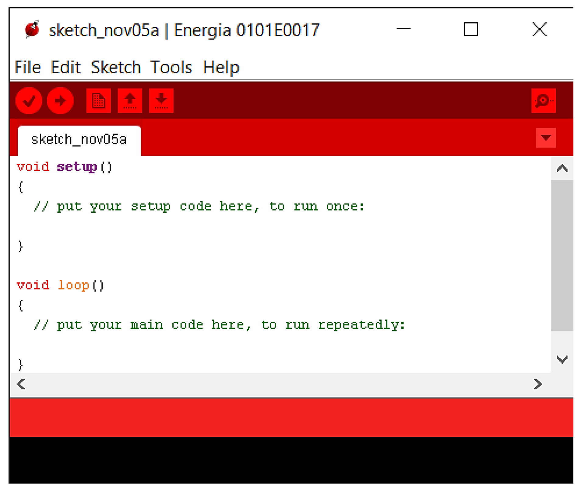
Figure 17.
Programming the PID controller through Energia GUI. Source: The authors.
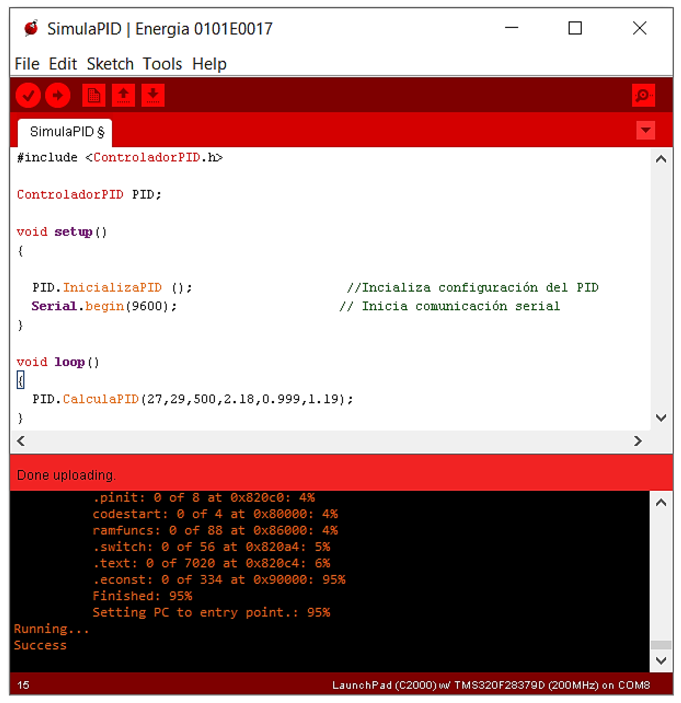
Figure 18.
Control loop implementation with the physical plant and the digital PID controller. Source: The authors.
Figure 18.
Control loop implementation with the physical plant and the digital PID controller. Source: The authors.
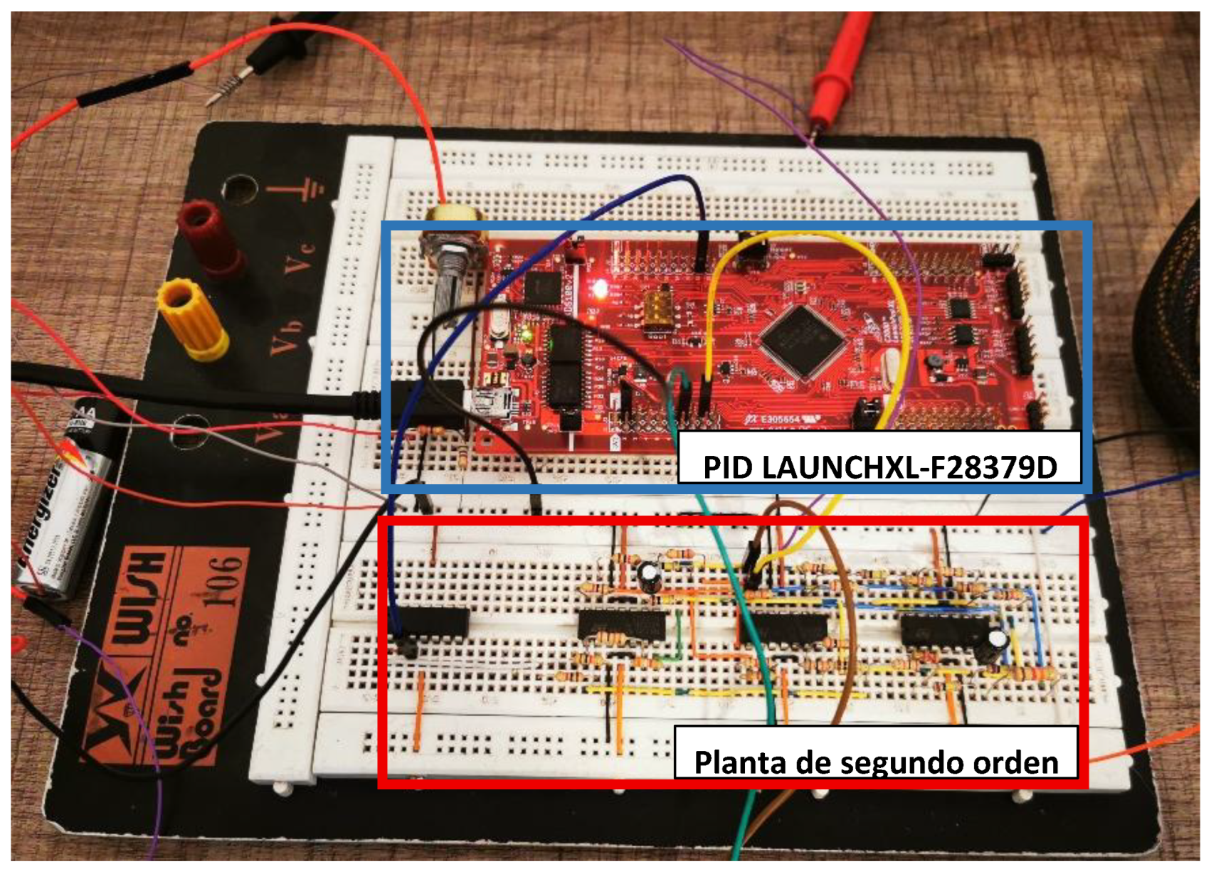
Figure 19.
Real-time performance of the PID controller in the second-order plant. Source: The authors.
Figure 19.
Real-time performance of the PID controller in the second-order plant. Source: The authors.
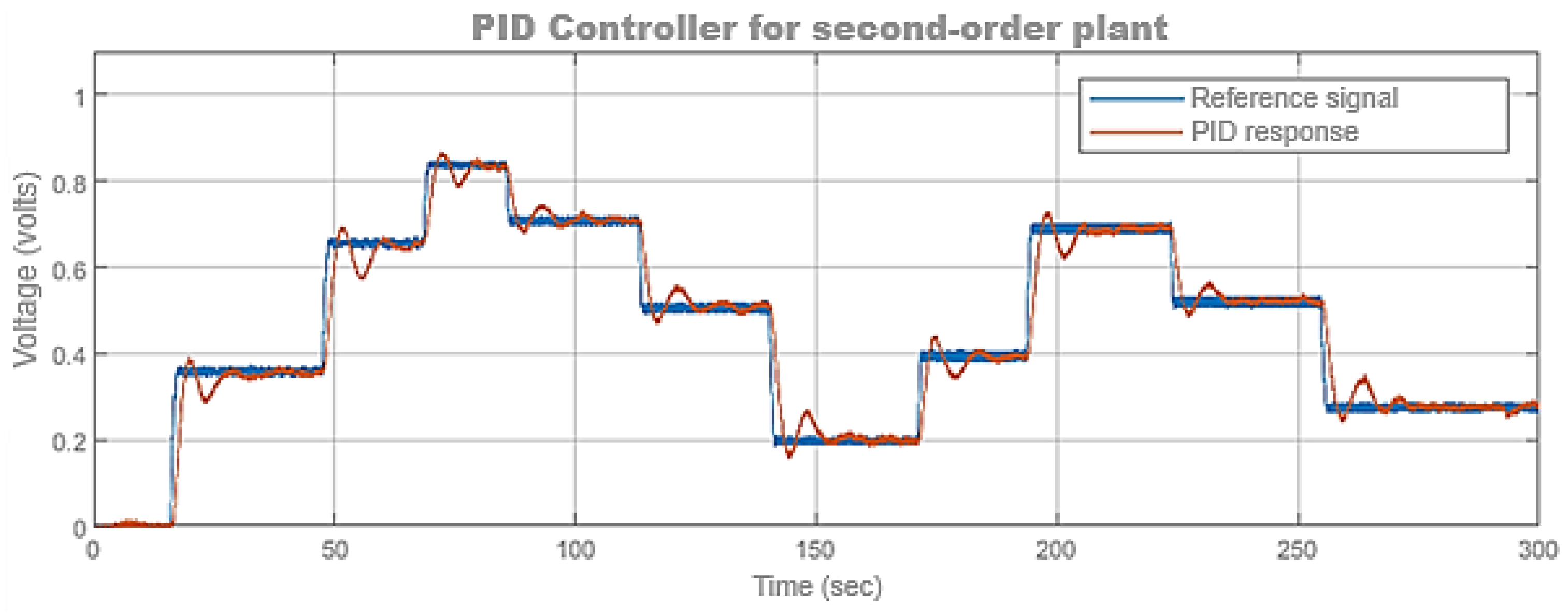
Figure 20.
Discrete-time control system for the flying cutting plant. Source: The authors.
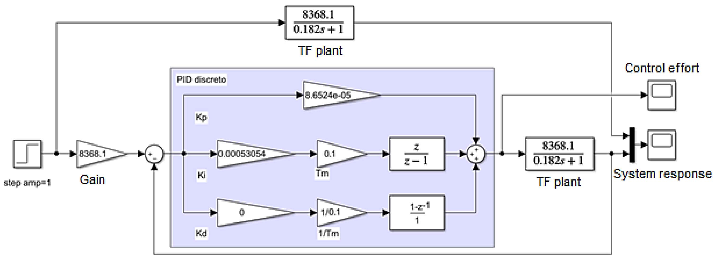
Figure 21.
Response of PI controller simulation in the flying shear plant. Source: The authors.
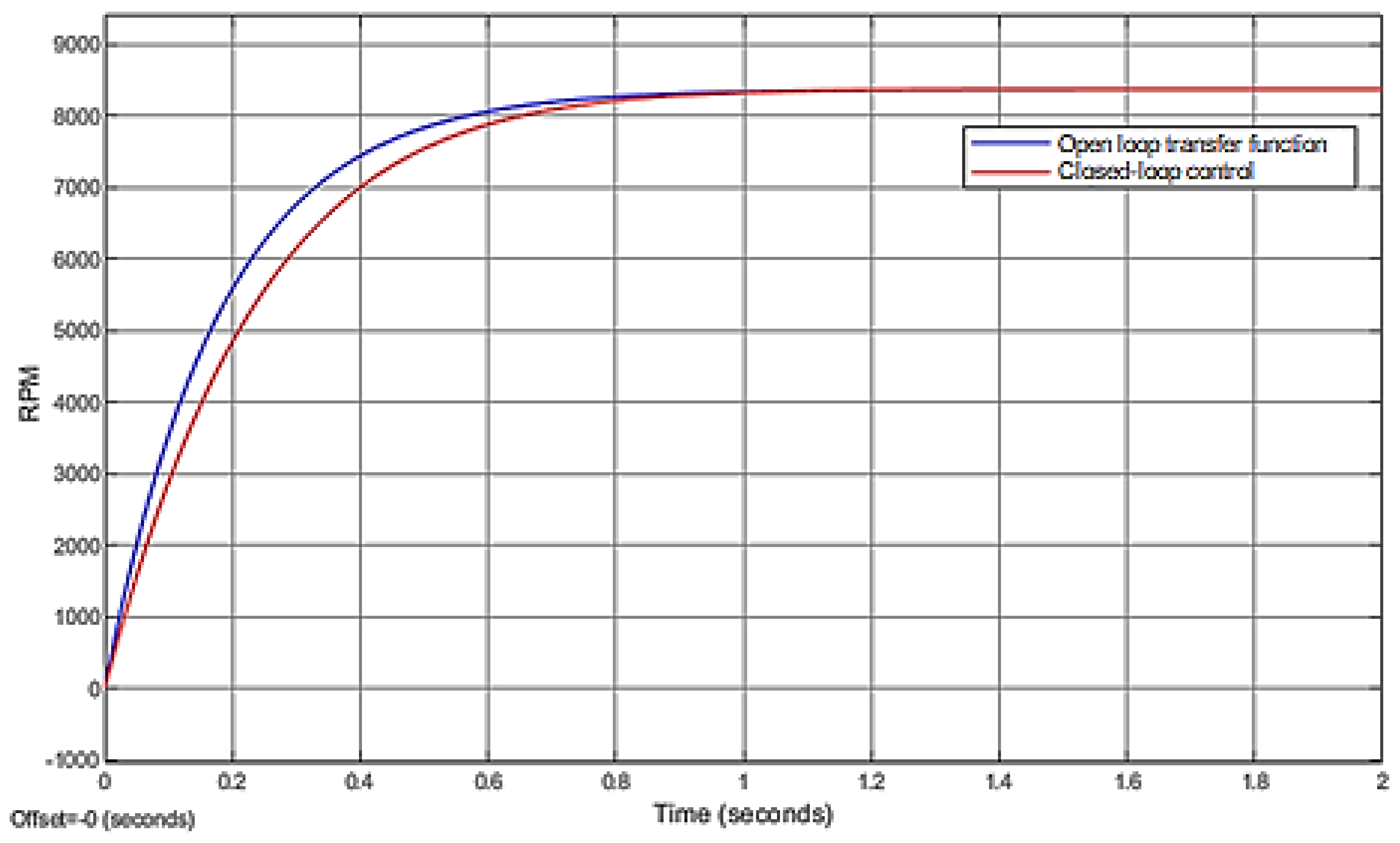
Figure 22.
Graphical user interface of the CCS IDE. Source: The authors.
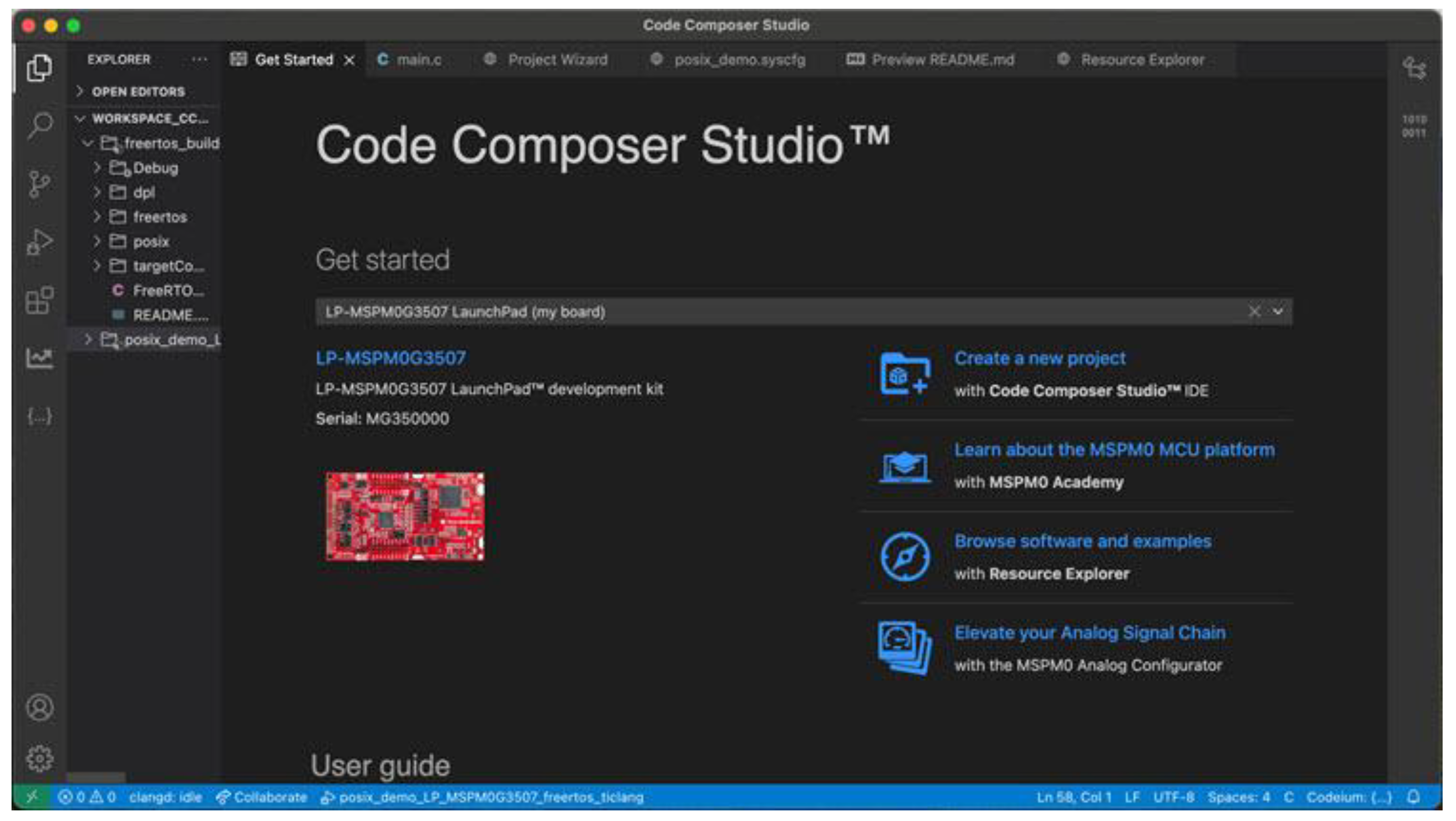
Figure 23.
Functions in CCS for the control and operation of the flying cutting plant. Source: The authors.
Figure 23.
Functions in CCS for the control and operation of the flying cutting plant. Source: The authors.
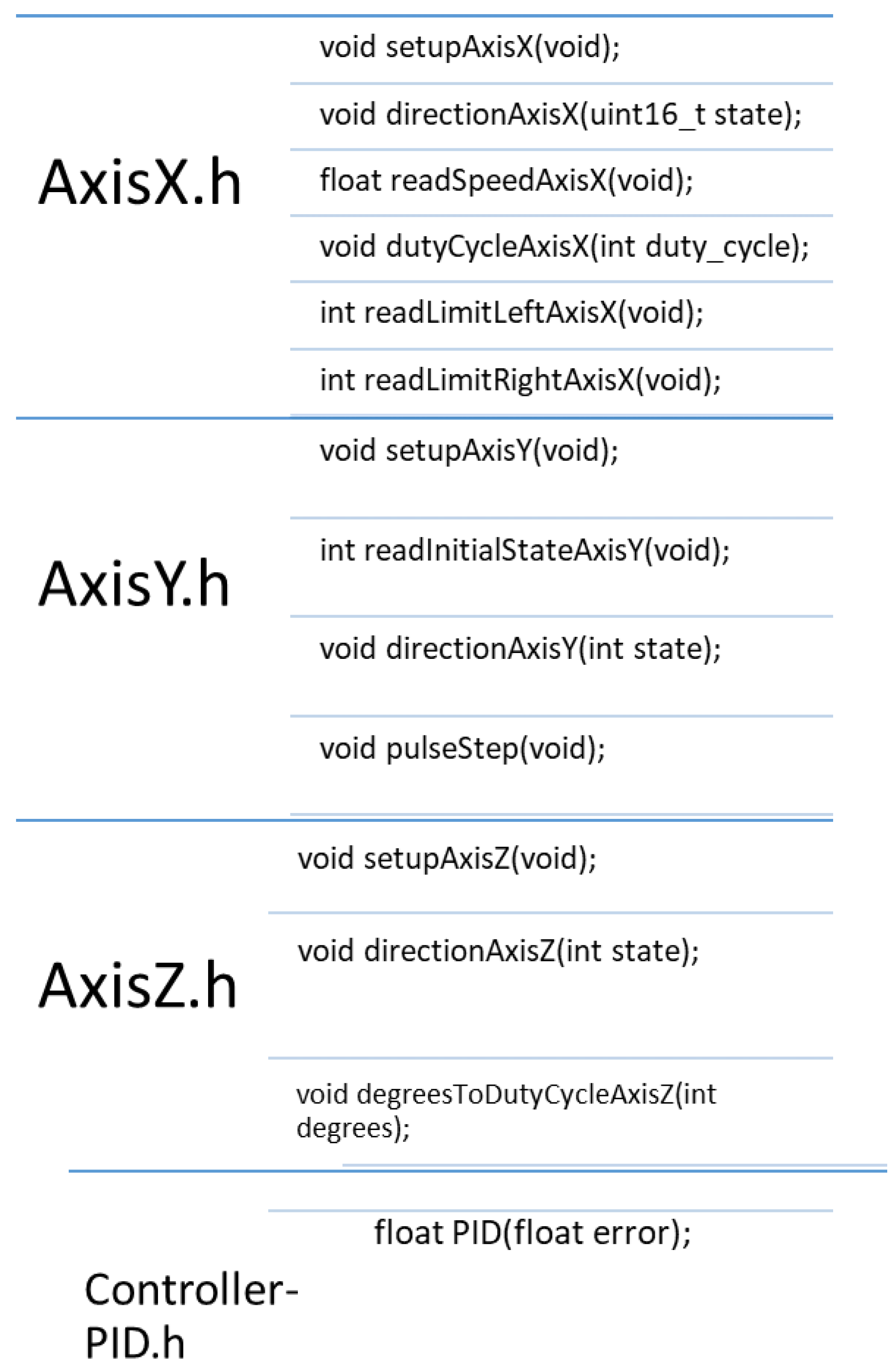
Figure 24.
Implementation of the control loop for the flying cutting plant and the digital PI controller. Source: The authors.
Figure 24.
Implementation of the control loop for the flying cutting plant and the digital PI controller. Source: The authors.
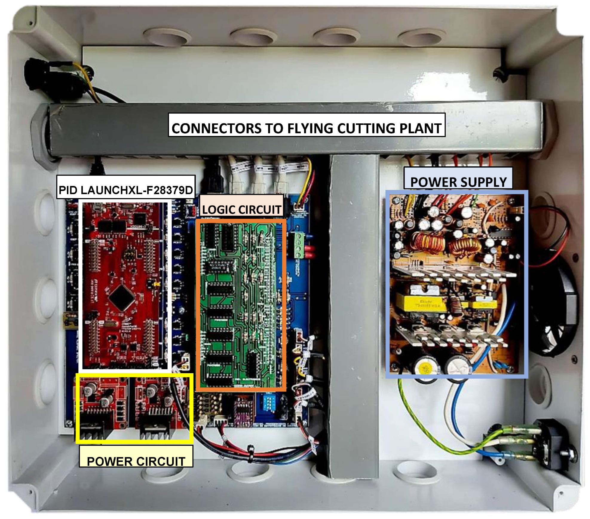
Figure 25.
Building prototype of the flying cutting plant. Source: The authors.
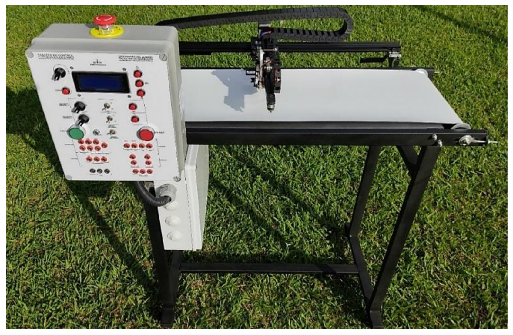
Figure 26.
Real-time performance of the PI controller in the flying cutting plant. Source: The authors.
Figure 26.
Real-time performance of the PI controller in the flying cutting plant. Source: The authors.
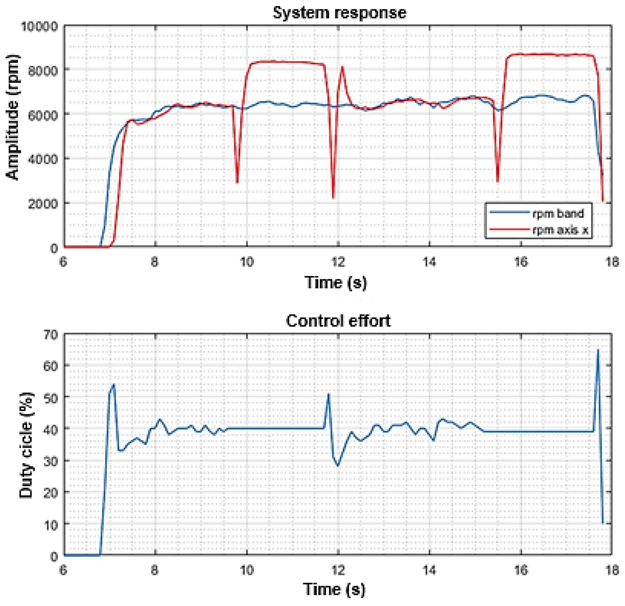
Figure 27.
PID controller setup on CPU1. Source: The authors.
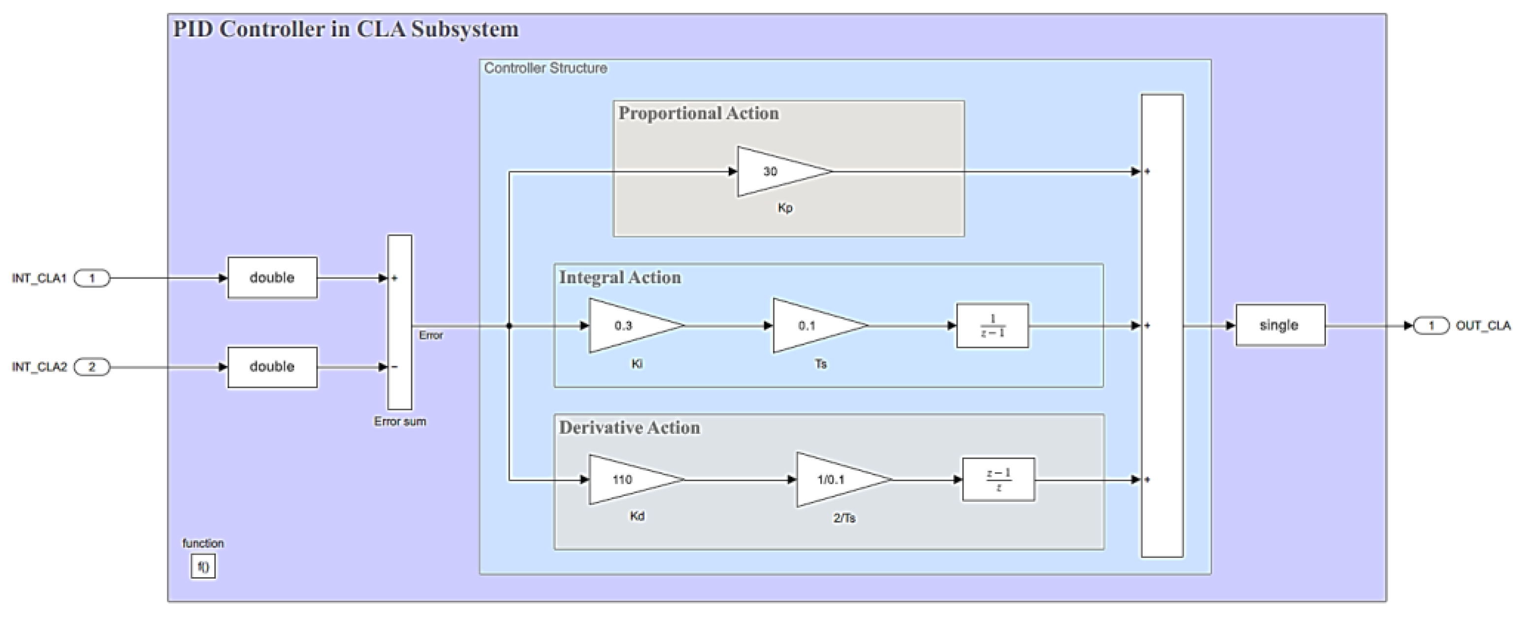
Figure 28.
Level plant setup on CPU2. Source: The authors.
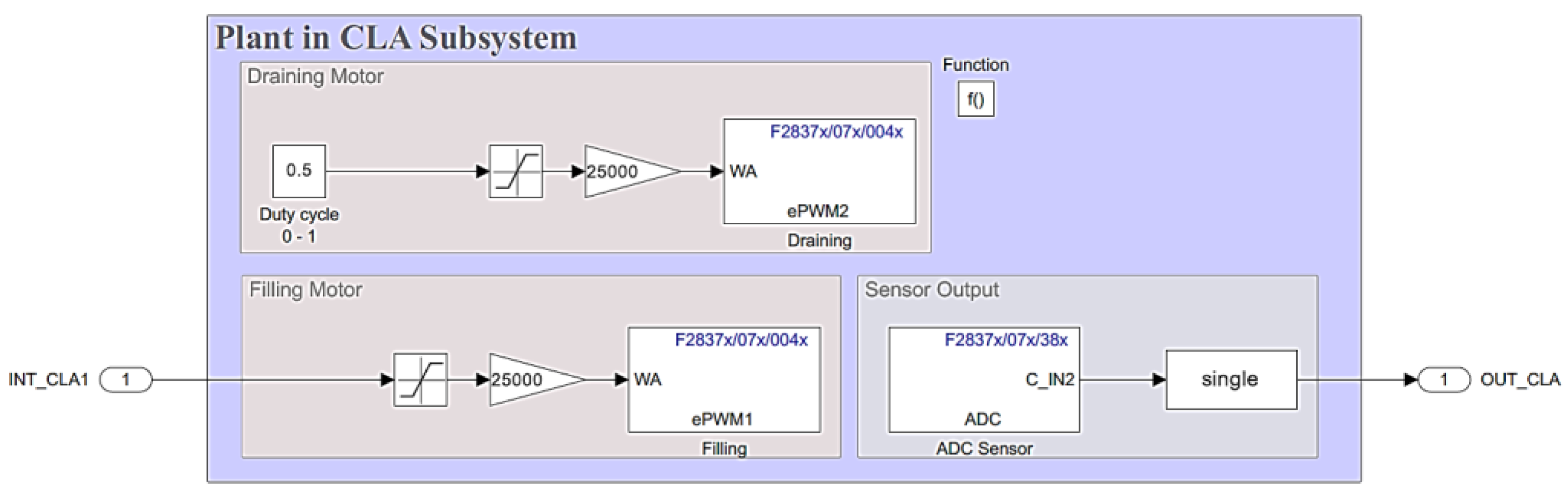
Figure 29.
Implementation of control loop for level plant and digital PID controller. Source: The authors.
Figure 29.
Implementation of control loop for level plant and digital PID controller. Source: The authors.
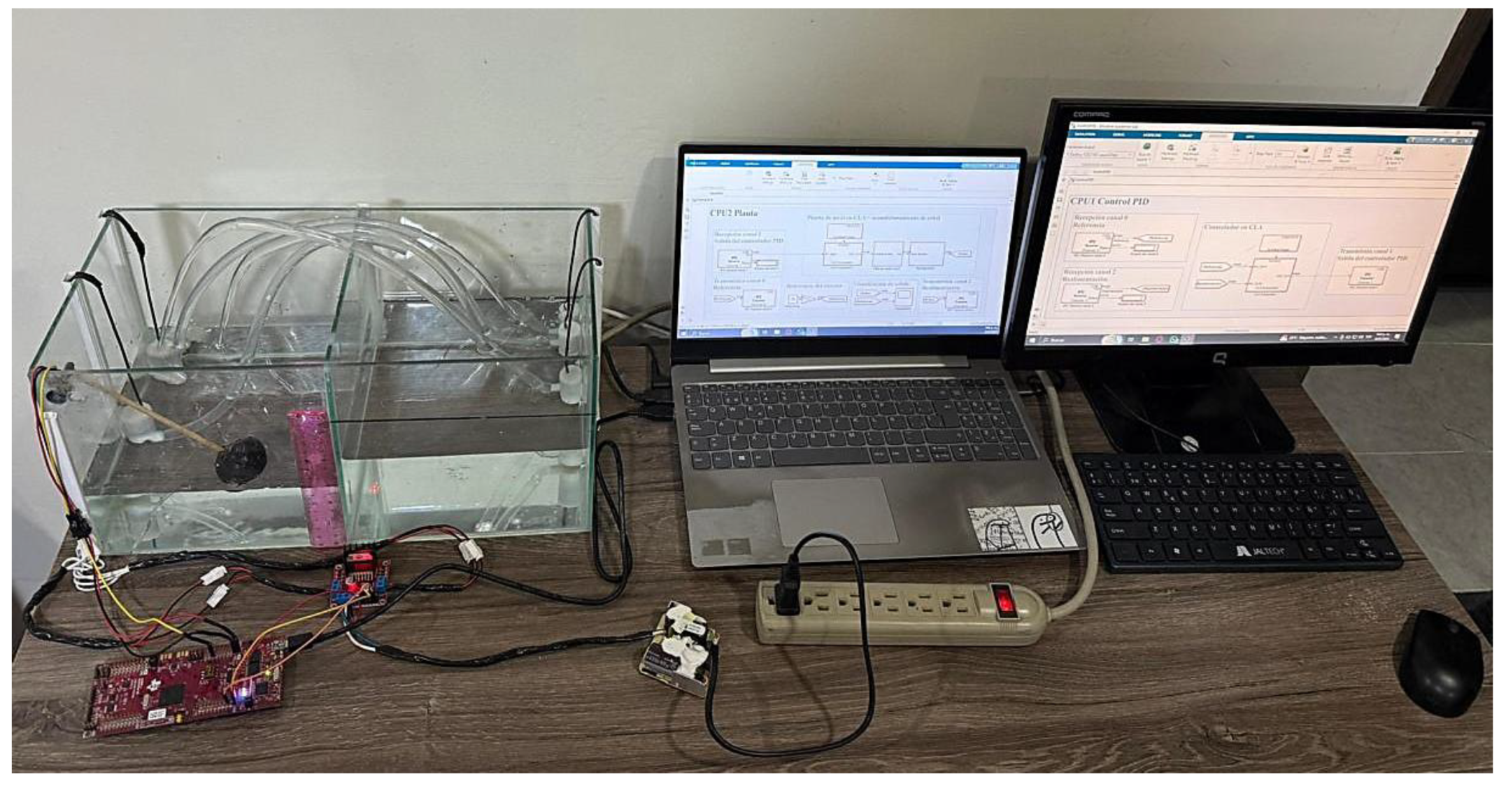
Figure 30.
Real-time response of the PID controller for the level plant. Source: The authors.
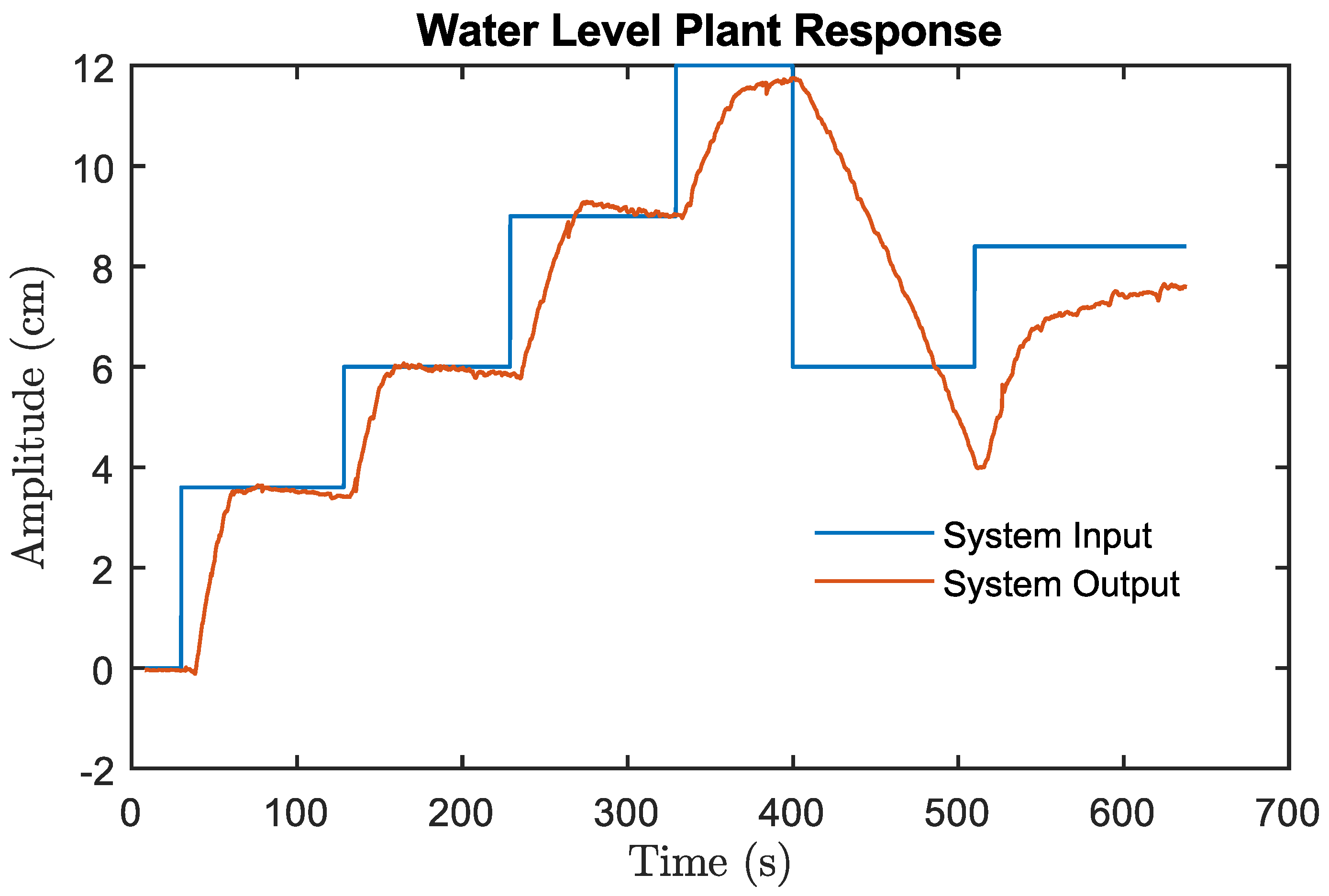

Table 1.
Equivalence between continuous and discrete systems for the PI controller.
| Action | taking and delay | ||
| Proportional | |||
| Integrative | |||
| Derivative |
Disclaimer/Publisher’s Note: The statements, opinions and data contained in all publications are solely those of the individual author(s) and contributor(s) and not of MDPI and/or the editor(s). MDPI and/or the editor(s) disclaim responsibility for any injury to people or property resulting from any ideas, methods, instructions or products referred to in the content. |
© 2025 by the authors. Licensee MDPI, Basel, Switzerland. This article is an open access article distributed under the terms and conditions of the Creative Commons Attribution (CC BY) license (http://creativecommons.org/licenses/by/4.0/).
Copyright: This open access article is published under a Creative Commons CC BY 4.0 license, which permit the free download, distribution, and reuse, provided that the author and preprint are cited in any reuse.


