Submitted:
06 November 2025
Posted:
10 November 2025
You are already at the latest version
Abstract
Multiband imaging (MBI) is a non-invasive, portable digital technique that has become increasingly widespread in the technical study and condition assessment of paintings, owing to its affordability, and ease of use. This paper presents an experimental research aimed at optimising MBI at the microscopic scale - referred to as micro multiband imaging (µMBI) - particularly with the aim of expanding its diagnostic capabilities. A range of µMBI techniques were used on custom-made mock-ups made up of pigments selected for their spectral responses, and representative of traditional artistic materials. The techniques used included microphotography of polarised and unpolarised visible light (µVIS), raking light microphotography (µRL), transmitted light microphotography (µTL), ultraviolet-induced visible luminescence microphotography (µUVL), infrared microphotography (µIR), infrared micro-transirradiation (µIRT), and infrared false-colour microphotography (µIRFC). The results obtained through µMBI were compared with those from standard MBI methods, allowing for a critical discussion of the strengths and limitations of this emerging approach. Results evidence that µMBI provides high-resolution, spatially specific insights into materials and painting techniques, offering a more detailed understanding at the microscale of how a painting was executed. It also enables the assessment of deterioration processes (e.g., cracking, delamination, and metal soap formation), contributing to a deeper comprehension of the origin and progression of failure phenomena and supporting the development of more informed, preventive conservation strategies.
Keywords:
micro multiband imaging (μMBI)
; digital portable microscopy
; multiband imaging (MBI)
; non-invasive and portable techniques
; reflection
; transmission
; luminescence
1. Introduction
In recent years, the technical analysis of works of art has undergone significant advances, driven by the development and application of methodologies based on non-invasive and non-destructive techniques. Multiband imaging (MBI) techniques are distinguished by their versatility and wide applicability to a range of heritage objects. Their relative simplicity of execution and interpretation, together with their portability, low cost and ability to provide a wealth of information on material, procedural and conservation aspects, make them particularly valuable tools in this field [1].
These techniques have been successfully used for the documentation and recording of various cultural objects, including textiles, papers, photographs, sculptures and, especially, both easel and mural paintings [2]. The increasing use of non-invasive analytical methods reflects the growing need to preserve the integrity of works, especially in contexts where minimal intervention or preventive conservation is prioritised. The combination of non-invasive techniques allows for a detailed characterisation of the object under study, reducing the need for sample extraction [3,4]. In this regard, the implementation and eventual development of portable, low-cost technologies presents a viable and accessible alternative for institutions with limited resources, without compromising the quality of the results obtained [5].
Despite the advantages associated with the use of sensors in a wide spectral range, the field currently faces significant challenges related to terminology and nomenclature [6], particularly with regard to the classification and standardisation of multiband techniques [1]. This lack of consensus makes it difficult to compare results between studies and to consolidate a common methodology. The nomenclature of the technique varies among authors: some use the term Technical Photography [7], while others prefer Multiband Imaging [8,9]. It should be noted that this type of imaging should not be confused with Multi Spectral Imaging, a term that is often mistakenly used to refer to this type of imaging. Multi Spectral Imaging can only be applied to images at specific points in the spectrum and not to band images. Although multispectral images are generally captured in different modes (reflection, transmission, luminescence, or even false colour) in different bands of the spectrum [1], they can also include other types of images. For instance, they may include X-rays or infrared reflectography taken in bands further away from the spectrum and with other types of sensors, although they are usually taken with the same device, generally equipped with a silicon sensor (CCD or, in recent years, more commonly CMOS). This type of sensor is commonly used in cameras—both compact and reflex—and has a spectral sensitivity ranging from approximately 300 to 1100 nm. However, manufacturers often incorporate one or more filters that restrict the sensor's operating range, limiting it mainly to the visible spectrum band. This means it loses its potential to capture information in the ultraviolet (UV) and infrared (IR) bands [10,11].
Conversely, advancements in augmented imaging technologies have led to the widespread adoption of digital magnifiers and surface microscopes equipped with CCD or CMOS sensors in recent decades. These compact and portable devices typically incorporate a bifocal lens and a perpendicularly arranged LED lighting system. These devices connect to laptops via USB, enabling users to view high-resolution images with variable magnifications ranging from 20x to 500x on the screen. These features make them particularly useful in various scientific and industrial fields, where they provide accurate images for analysis and research.
Portable digital microscopy is an essential tool for examining materials and structures in the artistic field, offering an enlarged view of phenomena at the microstructural level and revealing the morphology and appearance of materials on a scale different from that which can be seen with the naked eye. In recent years, this tool has gained popularity as a valuable asset in understanding the physical and material reality of heritage objects. It is employed for documenting their state of conservation and monitoring conservation-restoration interventions. This tool provides an alternative perspective to traditional photography and imaging techniques.
There are numerous manufacturers on the market who are investing in the production of portable digital magnifiers that operate in the visible range, sometimes with polarisation options. However, over the last decade, instruments that operate (apparently) in the IR and UV bands have become increasingly common. Despite the individual potential of these techniques, their combined use as a multiband protocol has not yet been explored, and there are relatively few references that systematically address a methodologically sound review of their uses in the visible band.
In light of the absence of comprehensive studies in this area, it is essential to establish a framework to guide future research. In this regard, the objective of this study is to evaluate the possible implementation of protocols based on multiband imaging techniques at the microscopic scale. The aim is to apply these techniques to the analysis of works of art and other heritage objects, with a special emphasis on the study of paintings. This approach is not at all trivial. It requires attention to the technical specifications — and, consequently, the possibilities — offered by the various instruments available on the market, considering both their technical characteristics and their capabilities and limitations.
The application of the micromultiband technique (µMBI), which represents a significant innovation in the field of heritage conservation, could be a fundamental tool in this type of study, especially when integrated with other methods of analysis. Additionally, µMBI can provide complementary data that promotes a deeper understanding of the results obtained through other types of analytical and documentation techniques.
This article will outline the working methodologies associated with this type of equipment, focusing on the different modes of image acquisition — reflection, transmission, luminescence, and false colour — with the aim of demonstrating the usefulness and applicability of these devices in the context of the technical and material analysis of cultural heritage.
The subsequent section outlines a strategy for the utilisation of optical microscopy, providing a rationale for its technical requirements and its application in case studies.
2. Materials and Methods
2.1. Materials Used
To verify the proposed methodology, four mock-ups were designed which, due to their characteristics, provide useful elements for the study of the paintings (Figure 1). These mock-ups were made using a plain weave linen canvas (7.5 x 7.5 cm) previously washed (degummed), and seven layers (120-320 µm, see Table A1) of Golden bright white acrylic primer were then applied. Canvas was chosen as support for being very common and versatile, allowing transmission techniques (TL, IRT) to be applied.
To illustrate the efficacy of the transmission techniques, two diagonal lines were drawn with a graphite pencil on the second layer (primer). The drawing was then covered with five additional layers of primer. Once the white primer had been applied, a grid was drawn with graphite to apply the pigments in a centred manner, which will also be helpful to position the digital microscope in the centre of the mock-up (Figure 1).
Eight ad hoc oil paints manufactured by Golden were used, corresponding to the following pigments: cobalt blue, raw Sienna, burnt Sienna, alizarin crimson, cadmium red, cadmium orange, cadmium yellow and titanium white. The paints were selected for their absorption, transparency and reflection properties, i.e. that is, their specific response within different spectral bands of the electromagnetic spectrum and are summarised in Table 1. The paint tubes are devoid of any additives, containing solely the medium (alkali refined linseed oil) and the pigment, so as to assess their behaviour across the different regions of the electromagnetic spectrum without interference from them. All the paint layers were previously characterised by spectroscopic analysis within an earlier research project, allowing the spectroscopic behaviour of the paint films to be already well understood.
The paint was applied using a brush. Due to the specific characteristics of each paint, the thickness of the applied layers is heterogeneous, generally ranging between 10-160 µm (see Table A1 for further details).
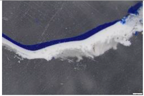
Two types of mock-ups were prepared. Type 1 mock-ups (corresponding to two different sets of mock-ups, M1 and M2) were painted with four different colours each: M1 contains cobalt blue, raw Sienna, titanium white and cadmium red, and M2 contains alizarin crimson, burnt Sienna, cadmium orange and cadmium yellow. (Figure 1) Cadmium pigments are particularly interesting for infrared analysis: they appear opaque and highly covering in the visible range but become remarkably transparent in the infrared band. In addition, cadmium and titanium–rutile whites exhibit infrared luminescence when excited by ultraviolet radiation. On the other hand, Siena earth pigments are highly absorbent in the infrared band and are often used in ground and priming layers. Finally, cobalt-based pigments show a strong luminescent response under ultraviolet light and remain fairly transparent in the infrared range.
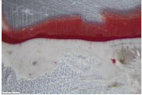
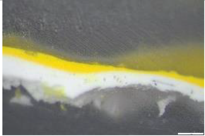
Type 2 mock-ups (M3 and M4) display two colour stripes on an underlying layer of burnt Sienna that covers half of the mock-up vertically in both M3 and M4. burnt Sienna was selected because it is absorbent in the infrared range (see Table 1). Specifically, M3 has a horizontal layer of titanium white and cadmium red, applied over the underlying layer of burnt Sienna. M4 instead has a horizontal layer of cadmium orange and another of cadmium yellow, on the burnt Sienna oil paint film. These four colours were selected for their transparency in the infrared range (see Table 1).
The mock-ups were mounted on a die-cut foam board, painted with black acrylic in order to avoid reflections, block the radiation in transmission techniques and avoid unwanted light contamination in luminescence techniques (Figure 2).
2.2. Equipment
There are a number of microscopes on the market that incorporate a linear polariser. These devices are engineered to minimise specular reflections and glare arising from incident radiation oriented normal to the surface, thereby reducing optical distortions and improving image fidelity. Conversely, several manufacturers are developing systems optimised for operation within spectral regions outside the visible one, particularly in the infrared (IR) and ultraviolet (UV) regions, to enhance imaging performance under diverse illumination conditions.
For the purposes of this research, it was decided to employ readily available commercial equipment, which has become widely accessible in most regions and offers a relatively cost-effective solution for implementation. Following a comprehensive assessment of the available alternatives, Dino-Lite was selected as the preferred supplier. This choice was primarily informed by the company’s extensive portfolio of models, each characterised by distinct technical specifications suited to diverse analytical requirements. Moreover, the brand’s well-established reputation within the conservation and restoration community, corroborated by preliminary market research, constituted a decisive factor in the selection process.
Following careful consideration, it was determined that the most practical option would be to utilise microscopes with a 1.3 MP resolution. These microscopes are the most prevalent and well-regarded in the sector, and they represent the brand's most cost-effective range. Consequently, they are the most widely employed within the industry. While there are models with higher resolutions, such as 8 MP, these are currently in limited availability and can cost up to three times more than 1.3 MP models. For reasons of operability and accessibility, it was decided to work with the company's standard range. It should be noted that all Dino-Lite microscopes are equipped with CMOS sensors, which have a sensitivity between 400 and 1100 nm if not filtered [1].
Based on the equipment selected, a range of µMBI techniques were employed, as outlined below. These techniques are abbreviated as follows: visible microphotography of ultraviolet-induced luminescence (µUVL); visible microphotography (µVIS); raking light microphotography (µRL); transillumination microphotography (µTL); infrared microphotography (µIR); infrared transirradiation microphotography (µIRT); and false-colour infrared microphotography (µIRFC) (see Table 2 for details).
All images in this study were recorded at 50X magnification . However, it is important to consider the recording scale, as a considerable increase can reduce the perception of certain lines, especially when working at magnifications close to 200X. At a magnification of 50×, the field of view is approximately 8.8 mm, corresponding to a spatial sampling of about 6.9 µm per pixel, with an effective optical resolution of around 4 µm.
The Dino-Lite AM4113ZT polarised microscope was used to capture images in the visible spectrum (by reflection, transmission, and visible luminescence induced by UV radiation) [12] (see Table 2 for specifications). The Dino-Lite AD4113T-I2V was employed for µIR and µIRT imaging, with a nominal magnification of 10×–70× (up to 200×) and a 1.3 MP CMOS sensor sensitive across 300–1100 nm. Preliminary testing was conducted (Table 2). Although marketed as an UV-IR microscope, the device operates as a full-spectrum system, utilising the entire sensor sensitivity range. As will be discussed, the device cannot be considered a UV microscope per se and operates effectively only within the IR range. The images were captured using DinoCapture 2.0 software, which is freely available from the manufacturer’s website.
For comparison with multiband standard protocols, the mock-ups were also recorded using MBI equipment. A full-spectrum digital Nikon® D800 camera (36 MP, CMOS sensor, sensitivity between 300 and 1100 nm) with a Nikon Nikkor 50 mm 1:1 coupled lens was used in this study. A CHSOS Robertina® 52 mm filter set was selected for capturing the various images.
To obtain VIS and IR images, two halogen lamps (800W) with a diffuser were used, while for transillumination and trans-irradiation techniques only one lamp was used, located on the back of the canvas, at a distance of 80 cm, coupled with a diffuser. For UVL, IRL, and UVR, a CHSOS Fabrizio UV high-flux 365 nm LED lamp was used (filtered and exclusively with UV passage and cut-off of the VIS-IR emission).
2.3. Working Conditions
With regard to lighting, the LED light source incorporated in the AM4113ZT microscope was used for the reflected image (µVIS). However, to obtain µRL and µTL images with the same microscope, an external LED torch equivalent to the LEDs incorporated in the equipment was used (Table 3). For the µUVL image obtained with AM4113ZT, two 365 nm UV torches (Alonefire SV18 12W) were used with the microscope turned off (Table 3). This ensured that the torches emitted only ultraviolet radiation, without any visible light or unwanted infrared emission. The UV radiation is what causes the materials to emit luminescence when irradiated. To obtain the µIR image, the LED radiation source integrated into the AD4113T-12V microscope itself was used, which emits at 940 nm. In the case of the µIRT image, an external LED torch equipped with 940 nm emitters (Ultrafire 501IR) was used, turning off the radiation source of the AD4113T-12V microscope during image capture to avoid interference (Table 3).
It should be noted that when using external light/radiation sources, as well as when capturing any of the photographs, it is necessary to work in an environment where ambient light can be controlled, preferably in total or near-total darkness, to avoid light pollution and ensure the reliability of the results.
The geometric arrangement of the light and radiation sources was adjusted according to each technique. For µVIS and µIR, the front source built into the microscope was used, while for µIRT and µTL, the lighting was placed at the rear of the mock-ups, at a distance of between 10-2 cm. In the case of µUVL, two front sources arranged at 45° were used, and for µRL, a single light source placed tangentially to the support was used (see Table 3). In summary, this geometry is comparable to that proposed for image capture in different modes [13].
The calibration of the images was achieved by utilising a CHSOS card [14]. This card incorporates pigmentary additions that respond to infrared (IR) and ultraviolet (UV) radiations. In addition, an X-Nite colour chart was utilised to facilitate a comparative analysis of the results. Furthermore, the exposure and white balance adjustment for both MBI and µMBI images was performed using patch N8 of the X-Nite colour chart, equivalent to N8 of the CHSOS chart. The response of the device in the IR band was measured and its exposure value was verified as equivalent to that of the visible range. The images were corrected to match the grey value. The decision to use this colour chart, as opposed to other systems such as Spectralon, is based on the observation that the material is heterogeneous, displaying under the microscope a mottled or marbled texture that is not represented in the aforementioned colour chart.
Finally, the hybrid µIRFC technique was used to compare its possible results with those obtained using standard IRFC images. Standard IRFC images are commonly used as auxiliary techniques for the preliminary identification of pigments, as well as for the detection of repainting or the visualisation of underlying elements linked to a colour pattern. In this instance, the image was created by combining µVIS and µIR, integrating their RGB channel using editing software (Adobe Photoshop®) [15].
3. Results
This section, which is dedicated to the results and their discussion, includes a series of methodological considerations. In the context of this work, these considerations constitute the true core of the analysis. Typically, such observations would be included in the methodology section; however, as this study focuses on the evaluation and issues arising in certain emerging technical practices, it was considered more appropriate to address them here, in direct dialogue with the results obtained. This choice is in line with the nature of the object of study: a set of procedures that still lack standardised protocols and whose effectiveness must be assessed on the basis of empirical tests, comparative analyses and qualitative technical observations.
The multiband images obtained with the reflex camera were compared with their analogue images obtained using multiband microscopy (Figure 2) with the respective Dino-Lite microscope. An analogy has been established for most techniques, with some limitations for others, as this study was carried out with commercial microscopes that cannot be manually filtered a priori. Observations of the results by modal families will be discussed in the following sections; that is, the images are grouped according to their nature, reflection, transmission, luminescence, and false colour. The possibilities and limitations observed will be then outlined.
3.1. Microscopic Imaging Techniques by Reflection
It is important to note that reflection-based techniques (VIS, IR, and UVR) yield results fully comparable to those obtained with standard microscopy systems equipped with dedicated illumination or radiation sources (see Figure 3 and Figure 4). The AM4113ZT model (featuring integrated LED illumination) and the AD4113T-I2V model (equipped with UV/IR LEDs) are both suitable for such applications. However, unlike conventional VIS and IR configurations—where oblique illumination is typically preferred [14]—these microscopes employ a light source positioned perpendicular to the sample plane. This geometry can produce unwanted reflections and glare, particularly in the visible range. As shown in Figure 3, the microscope images of M1, M2, and M3 display surface gloss on titanium white and alizarin crimson areas, which is not present in the corresponding MBI image
The AM4113ZT model offers two significant advantages over other microscopes operating in the visible range. Firstly, it allows for the use of external light, with the device's LEDs turned off. Secondly, it incorporates a coupled polariser, which is highly useful for the study of paintings. Indeed, binders such as oil and other satin finishes have been found to produce excessive gloss, depending on the lighting geometry, especially in the presence of varnish – a common occurrence in paintings – and in dark-coloured areas. The implementation of a polarisation system constitutes an effective strategy for mitigating this phenomenon, as it markedly attenuates surface gloss—an inherent and frequently problematic characteristic of conventional MBI imaging. Although the suppression of gloss is not absolute, the polarisation approach provides a robust and reproducible improvement in image quality. Furthermore, the diverse imaging modalities afforded by the use of polarisers can yield highly informative data regarding the physicochemical and morphological characteristics of the pictorial surface. Such information is of particular relevance to conservation professionals, facilitating the documentation and assessment of varnish layers and their state of preservation.
Please note that the use of polarising filters can result in slight alterations to colour tonal values. Despite the evident disparities in terms of image scale, lighting geometry, device resolution and sensor characteristics, which, although they belong to the same technological family, exhibit divergent performance levels, a comparison of the images obtained with a Digital- Single lens reflex (DSLR) camera and those captured with a digital microscope reveals relative chromatic consistency. It should be noted that, in contrast to a reflex camera, it is not possible to manually adjust key parameters such as shutter speed, aperture, or ISO sensitivity in a microscope. This introduces further constraints to image capture. Despite this, the images obtained show satisfactory colour correspondence for the purposes of technical analysis.
The AD4113T-I2V microscope was operated in infrared (IR) mode. The instrument provides three selectable radiation configurations: the first activates the ultraviolet (UV) LEDs, the second engages the infrared (IR) LEDs, and the third allows image acquisition without the use of any internal illumination source, thereby requiring the employment of an external radiation source. The device is not equipped with an optical filter in front of the sensor, rendering it a full-spectrum detector with a sensitivity range of approximately 300–1100 nm. When operated with the integrated IR LEDs (emitting at 940 nm, a wavelength invisible to the human eye and devoid of visible light emission), image acquisition must be conducted in darkness to avoid contamination from ambient light or stray UV radiation, both of which could be detected by the sensor and compromise the accuracy of the results.
The images captured exhibit a violet hue, consistent with the characteristics of infrared imagery captured using DSLR cameras. Therefore, it is necessary to convert them to greyscale, as is standard practice when correcting IR images in MBI [14,15,16].
When the paint layer is not completely opaque (a factor that depends on the materials present, their concentration, and the thickness of the film), IR images facilitate the observation of the lines of the underlying drawing. Pigments that appear transparent in reflected IR behave similarly in their µIR variant. As with conventional multiband imaging, it can sometimes be useful to adjust the contrast, tonal depth or definition of the images in order to optimise the visualisation of certain technical details [11,12,13,14,15,16].
For the mock-ups analysed, the μMBI response of the pigments was consistent with that observed using the MBI technique. In Type 1 mock-ups (M1, M2) (see Figure 4), the burnt Sienna and raw Sienna pigments appear dark due to their intense absorption in the IR range. In contrast, cobalt blue, cadmium red, titanium white, alizarin crimson, cadmium orange and cadmium yellow are transparent in the IR. In both cases, the graphite grid is visible, similar to the IR result of MBI. In the case of Type 2 mock-ups, the burnt Sienna pigment in the underlying layer becomes visible, as can be seen particularly in mock-up M3. This aligns with the established MBI framework.
As for acquiring µUVR (micro ultraviolet reflected) images, this would have required significant modifications to the design and internal structure of the microscope, potentially compromising its infrared imaging capabilities. In conventional models from Dino-Lite microscope and other similar brands, this type of recording is not feasible, as it would involve filtering both the radiation source and the sensor, which would need to be optimised to operate exclusively below 400 nm.
The AD4113T-I2V model, for instance, is equipped with LEDs that emit at 365 nm, but also generate a significant amount of parasitic visible light in the blue band of the spectrum. Therefore, despite being marketed as a device capable of operating in the IR and UV ranges, it cannot be considered an effective system for obtaining reflected UV images. The product's nomenclature pertains exclusively to the type of LEDs it incorporates, rather than its actual operability in those spectral regions. It is important to raise awareness of this potential confusion, given the widespread use of the model in the field of conservation-restoration.
Despite the implementation of a correctly filtered external UV lamp, µUVR image recording remains unfeasible. In conditions of controlled darkness, which are essential to avoid light interference, UV irradiation typically induces luminescence in the visible spectrum of some pictorial materials (and even in the infrared spectrum for pigments such as cadmium red and rutile). If the sensor does not have filters that block both the visible and infrared regions, it will record both of them. This technical limitation prevents the acquisition of reflected UVR images with currently available microscopes operating in this spectral range.
Finally, µRL has also been documented, given its importance in establishing the texture of the surface at a visual level. The AM4113ZT model was used in off mode for recording µRL images, using external LED lighting tangentially to the surface. The results obtained are particularly representative of establishing the texture of the materials used, the morphology and direction of the brushstrokes, and in some cases (as can be seen in M1 and M2) the texture of the support [13] (Figure 5).
3.2. Transmission Microscopic Imaging Techniques
For transmission imaging applications, both the AM4113ZT and AD4113T-I2V microscope models were found to operate effectively. In this technique, the illumination normally emitted by the microscope must be deactivated, and image acquisition should be performed with the LEDs switched off while keeping the sensor active. Both models are equipped with a function that facilitates this configuration. During the acquisition process, the microscope is gently positioned on the area of interest on the front surface of the painting, while the radiation source is placed at the back, following the conventional setup used in transmission methodologies [13].
To carry out µTL, it is therefore necessary to use an external light source, working with the device's LEDs turned off. It is recommended to employ a light source as similar as possible to that integrated into the microscope itself, such as a LED torch or a second microscope functioning as an emitter from the reverse side of the artwork. However, any visible light source may be used if these options are not available. Nevertheless, to standardise the procedure and facilitate comparability between the images obtained, it is preferable that the lighting used is homogeneous and of comparable intensity. The effectiveness of this technique depends primarily on the nature of the pigments present in the artwork [17,18], although its applicability is generally limited [2] (Figure 6).
In this case, it was observed that mock-ups containing a burnt Sienna underlying paint layer effectively prevent light transmission, as previously reported [18]. The limited power of the LEDs integrated into the microscope considerably restricted the penetration of the radiation emitted by them into the paint layers, so that only highly translucent pigments allowed light to pass, especially when applied in thin layers or glazes.
With regard to Type 1 mock-ups (M1 and M2), only in the area covered by titanium white in M1 it was possible to clearly visualise a diagonal line drawn in the underlying layer in the µTL image, which is less evident in the MBI image (Figure 6). The pigment that exhibited the highest light transmission in M2 was cadmium yellow, consistent with the µTL results and MBI; however, the underlying drawing remained invisible. In Type 2 mock-ups (M3 and M4), the underlying burnt Sienna became visible when the light emission was deactivated and the titanium white layer in M3 permitted partial transmission. The microscopic image of M4 exhibited only minimal light transmission, a characteristic also observed in the corresponding MBI image. Overall, the results obtained from the microscopic images closely corresponded to those from MBI.
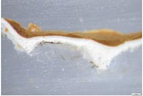
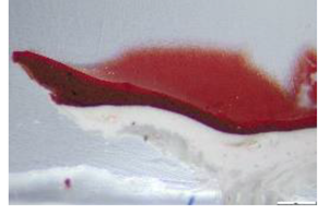
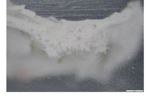
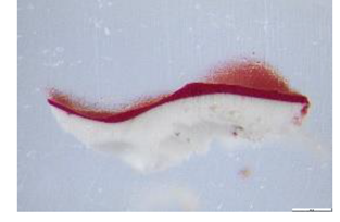
The images obtained using µIRT are particularly informative, as the technique is based on the same physical principles as conventional IRT. In this approach, infrared radiation can often penetrate all layers of the painting, provided that the support exhibits a certain degree of translucency [17]. The advanced capabilities of µIRT's enable the visualisation of hidden elements, including underlying drawings, compositional modifications, reworked areas, and traces of earlier phases that have been covered by a second primer or subsequent paint layers.
The main difference between wide-field and microscopic imaging lies in the depth of field, which becomes significantly reduced at the microscopic level. Given that the different elements may be located at different depths within the pictorial layer, obtaining a sharp and uniform focus for the entire image becomes complex. It is therefore common for certain areas to appear out of focus when the elements are distributed across markedly different planes. In this context, Figure 7 shows the images acquired from mock-ups M1 and M2 using the microscope. In both cases, the underlying cross-shaped drawing appears out of focus, as it is situated within the lower paint layers.
The response of materials in IRT, as well as in IR, depends directly on their chemical properties, concentrations, and relative thickness of the paint layer. Consequently, under these conditions, some underlying lines may become clearly visible, whereas others remain obscured if covered by thick or highly absorbent materials. It should also be noted that preparatory drawings are only detectable in infrared imaging when sufficient contrast exists between the drawing and the substrate on which it was applied.
In order to produce µIRT images with the AD4113T-I2V microscope, it is necessary to work in complete darkness. The microscope should be positioned on the front of the painting, and the unlit position (LEDs off) should be activated. At the same time, an infrared radiation source must be placed on the reverse side of the support: preferably, a torch equipped with 940 nm IR LEDs (such as those incorporated in the device itself) or a second Dino-Lite microscope activated in IR mode, which acts as an emitting source.
It should be emphasised that traditional sources used to obtain IR or IRT images on a macro scale, such as halogen lamps, incandescent lights, or flashes, are not suitable for this type of microscopic recording. This is due to the fact that they simultaneously emit visible light, which is captured by the microscope's full-spectrum sensor. In addition to this limitation, a more significant concern—though not related to measurement accuracy—is the potential risk to the artwork itself. Macroscopic radiation sources that are not intended for microscopy can emit substantial amounts of infrared radiation, which may lead to localized temperature increases within the materials of the artwork, thereby potentially compromising its stability and long-term conservation.
In the case of the mock-ups the technique proved entirely successful. Mock-up M1 demonstrates that all the pigments employed allow, to varying degrees, the transmission of IR radiation in the mode commonly referred to as IRT (Figure 7). The four colour fields indicate distinct responses. Raw Sienna (upper left quadrant) forms more opaque regions in areas of higher pigment concentration, showing greater absorption, although it does not entirely block µIRT and IRT radiation. Cobalt blue, cadmium red and titanium white exhibit partial translucency, brushstrokes in the case of red and white, and thereby providing information about the underlying layer.
This behaviour is also confirmed in M2. Alizarin crimson (upper left quadrant) presents exceptional transparency, even allowing the texture of the textile support to be discerned. Burnt Sienna (lower left) shows a higher degree of opacity, comparable to that of raw Sienna. Both the orange and yellow fields (in the upper and lower right quadrants, respectively) show partial translucent, allowing clear visibility of the brushstrokes and disclosing some information from the underlying layer.
In Type 1 mock-ups (M1 and M2), the image obtained reveals a cross-shaped drawing on the underlying plane, executed on the second layer of prime (7 layers in total). This observation highlights the high penetration capability of the technique, even though successive primer layers and paint applications. The motif appears out of focus due to the inherent limitations of the microscopic scale, which are significantly more restrictive than those in conventional IRT images.
In Type 2 mock-ups (M3 and M4), a comparison between the colour microscopic image (µVIS) and the corresponding transmitted infrared image (µIRT) reveals a phenomenon of radiation blocking. As illustrated in µVIS, image clearly shows the superimposition of a white and red layer in M3 and a yellow and orange layer in M4. However, in the µIRT image (Figure 7), the right-hand side of both mock-ups appears completely opaque to radiation, unlike the left-hand side, where the infrared radiation is able to partially penetrate the layers. It is important to note that this opacity is not due to an inversion of the image or a difference in surface composition. Rather, it is due to the underlying presence of a vertical strip of burnt Sienna. Due to its optical properties, this strip prevents the passage of infrared radiation. This scenario highlights the necessity to consider not only the surface layers, but also the presence of IR-opaque basal layers, which can compromise the interpretation of transmitted images.
3.3. Microscopic Luminescence Techniques
Among luminescence techniques, ultraviolet-induced luminescence (UVL or UVF, when the term "fluorescence" is used) is particularly noteworthy due to its long-standing application in conservation, although the term UVL is more precise [12]. This is arguably the most widely used technique among the set of multiband techniques since the early 20th century, although it is not always conducted with the requisite rigour or technical precision.
It is important to distinguish between the simple observation of a heritage object under UV radiation and the systematic acquisition of a luminescence image. These two actions are often confused, as both record or document a response in the visible spectrum induced by a UV lamp. It should be noted that the UVL technique essentially involves capturing an image in the visible range, which records luminescence phenomena occurring within this band but induced by a ultraviolet radiation [11,12]. In order to ensure the desired outcomes are achieved, it is imperative that both the radiation source and the camera are correctly filtered. It means that the source should only emit ultraviolet radiation, thus eliminating all emissions in the visible and infrared ranges. It is important to note that fluorescent lamps (such as Wood lamps) are likely to emit this type of parasitic radiations. Furthermore, many commercially available UV lamps lack appropriate filters, making them unsuitable for acquiring UVL images [2]. Nevertheless, they can be useful for direct observation of paintings, enabling the detection of repainting or certain luminescent areas, although the results are often partial and exhibit a pronounced bluish hue due to the presence of parasitic visible radiation. In addition, the camera must be equipped with suitable filters to transmit only the visible to the sensor while eliminating contributions from ultraviolet and infrared radiations.
At first glance, the AD4113T-I2V device might appear to be the most suitable for this technique, as it is marketed as a UV-IR microscope. However, this is not the case. As noted previously, the device lacks dedicated filters due to its full-spectrum functionality, preventing the placement of a filter in front of the sensor. Furthermore, the ultraviolet radiation source is unfiltered, causing the sensor to record visible and infrared radiations in addition to the luminescence phenomenon. Even when using a properly filtered external UV lamp, the device remains unsuitable, as it also records luminescence phenomena in the infrared. Consequently, the resulting images display colours that differ substantially from those perceived by the naked eye and cannot be considered faithful representations of the actual visible response, rendering them unrealistic.
In contrast, the AM4113ZT model is useful for this technique, as it has a bandpass filter that blocks infrared and ultraviolet radiations allowing only the luminescence induced in the visible to be recorded when used in front of external and adequately filtered UV radiation sources.
While larger lamps, such as the Fabrizio lamp mentioned above, are useful for imaging in the UV and µUVL ranges, certain practical limitations must be considered. The microscope itself often casts a shadow on the object, obscuring the induced luminescence and complicating documentation, while projecting the radiation precisely onto the device’s focal point can be challenging. In this context, it is more effective to use two handheld lamps positioned at an angle to the support (approximately 30º to the horizontal, or less). To direct the radiation through the transparent plastic lip surrounding the microscope’s aperture, the lamps should be positioned nearly tangentially to the plane of the support. Using a single lamp generates a raking light effect, which, although useful for visualising certain features, such as texture or specific surface alterations, does not permit effective capture of induced luminescence, as the illumination of the surface is not homogeneous.
In this case, the use of these images enabled the luminescence of cobalt blue and alizarin crimson applied to M1 and M2, respectively, to be documented (see Figure 8). In both instances, the luminescent response is comparable to that observed in µUVL and conventional UVL. As noted above, the shadows present in the microscopic image are reduced through the use of the two UV light sources, which provide more homogeneous illumination. It is also noteworthy that titanium white exhibits a very subtle luminescence, which was successfully captured by the microscope in both M1 and M3. These observations highlight the effectiveness of the technique, even in cases where luminescence is not immediately apparent.
Regarding the use of infrared luminescence techniques (µIRL), whether induced by visible (µVIL) or, in particular, by ultraviolet radiation (µUVIL), it was not possible to obtain results due to the previously mentioned inability to adequately filter the AD4113T-I2V microscope sensor. The sensor necessarily had to operate in the infrared range rather than across the full spectrum. This condition is critical, because unlike UVL —which can be documented, albeit partially and with altered chromaticity, even without perfect filtering—infrared luminescence is obscured by parasitic light and cannot be captured if the capture system is not properly optically filtered.
3.4. False Colour Microscopic Techniques
False-colour microscopy images represent a highly promising field of research in the area of multiband documentation applied to cultural heritage. These images are considered hybrid, as they are generated by merging a visible image with another captured in a non-visible band, either infrared or ultraviolet [11], in reflective or transmitted mode [19]. The two images are then processed using specialist software to create an overlapping fusion. Depending on the technique, the red channel of the visible RGB image is replaced by the corresponding channel of the infrared image, or the blue channel by that of the ultraviolet image. The remaining channels are subsequently reorganised, producing images with unreal colours that are nonetheless highly informative. Such images are particularly valuable for pigment identification, mapping repainting, and documenting surface alterations or other material interventions [2,3,4,5,6,7,8,9,10,11,12,13,14,15,16,17,18,19]
To obtain this type of image, two captures are required: one in visible and one in infrared, either reflected or transmitted, using the two different devices as described above. This procedure entails a certain degree of technical complexity, as it is essential to maintain precise alignment between the two captures. When changing microscopes, the image must be repeated at the exact same position, which can be challenging. Depending on the visual response obtained, the orientation process may become particularly difficult complicated. Therefore, it is recommended to use a marker or template to facilitate the repositioning of the device, enabling the previous sampling point to be accurately located as a reference. It is critical that the microscope is not rotated between shots to ensure consistent alignment. Nevertheless, unintentional rotations often occur during handling, typically ranging from 1º and 3º relative to the perpendicular axis. Such misalignments must be corrected during post-processing by adjusting the rotation of one image until it matches the other.
The µIRFC images exhibited a colour response closely matching the results obtained using IRFC with DSLR cameras, thereby validating the effectiveness of both infrared and visible captures (Figure 9). Although differences in scale and surface texture may induce perceptual differences, the tonal response of the pigments shows substantial correspondence between the two techniques. This behaviour has also been confirmed in additional tests, consistent with the typical chromatic patterns characteristic of this type of imaging [2]. Such recordings are widely employed to preliminarily identify pigments, map their distribution, and detect pigment variations within apparently homogeneous areas, owing to their differing spectral responses.
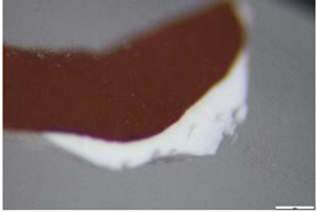
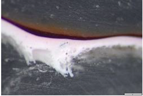
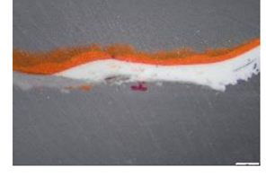
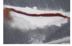
It is important to note that the µIRTFC images proved to be even more relevant. These images combine the characteristic chromatic response of each pigment with structural information about the stratigraphy of the painting, in a manner comparable to that obtained with DSLR cameras (Figure 10). This technique provides data on the nature and behaviour of the translucent support and reveals features such as variations in the thickness or homogeneity of the paint layer, as well as the presence of underlying stains, concealed elements, retouched areas, and in particular, the preparatory drawing. Overall, given its recent development, it is generally more efficient than reflected infrared images. Moreover, µIRTFC represents one of the most promising approaches within multiband analysis applied to artworks on translucent supports [19]. However, its application at the microscopic scale highlights the need to build a comprehensive comparative corpus, supported by well-documented case studies, to establish robust interpretative criteria and consolidate its analytical potential.
Finally, it should be noted that the current sensor limitations prevent the capture of µUVR images and, consequently, the generation of µUVFC images. While this technical constraint does not compromise the overall validity of the protocol, as a whole, it highlights an area for improvement in future versions of the system.
4. Conclusions
The micro multiband methodology (µMBI), as applied in this study, represents a novel protocol that remains in the early stages of development. To the best of our knowledge, this is the first study to systematise the application of multiband techniques at the microscopic scale using portable digital microscopes, and to describe a complete operating protocol for their use in the technical analysis of paintings on translucent supports. This approach opens up a largely unexplored field of research, offering significant potential for experimentation, methodological refinement, and validation of results.
The results obtained in this study demonstrate the effectiveness of micromultiband imaging techniques in documenting aspects related to the optical properties of pigments, their behaviour under different wavelengths, and their arrangement and material application on the pictorial surface. Images captured using µVIS (with and without a polariser), µRL or µIRFC have enabled the assessment of factors such as brightness, surface texture, and the presence of varnish. Other techniques, including µIR, µIRT, and µIRTFC, have revealed hidden structures, pigment accumulations, stratification irregularities, and traces of underlying drawings. The µIRT technique, in particular, has proven effective in highlighting variations in the homogeneity of the layers and in the translucency of the support. Conversely, the µTL technique has provided less revealing results due to the limited light penetration in the mock-ups under study; however, it has successfully shown the underlying drawing and support texture when permitted by the thinness and characteristics of the pigment layers. Luminescence recording was also achieved using µUVL, which captured emissions ranging from high to subtle intensity. The observed colour correspondence between the microscope records and their standard-scale (DSLR) counterparts further reinforces the suitability of the device for certain types of technical analyses.
Multiband microscopy offers several notable advantages, including portability, lower cost compared with conventional laboratory systems, the ability to capture images with and without polarised filters, a wide range of magnifications, and compatibility with multiple operating systems. It also enables the observation of pigment grain sizes, textile fibre twists, and stratification structures at varying depths, providing valuable information for both the study of artistic techniques and the assessment of conservation conditions.
However, certain limitations have been observed when using these devices. For some modalities, operation may require at least two operators, increasing logistical complexity. Extreme caution is necessary to avoid applying undue pressure when the device comes into contact with the surface. Additionally, images captured at higher magnifications exhibit a reduced depth of field, complicating the accurate d documentation of certain textures. Although the sensor resolution is sufficient for most applications, it may not meet more demanding analytical requirements. Finally, the current inability to filter the sensor limits the scope of results, preventing the use of techniques such as µUVR or µIRL (VIL and UVIL).
Despite these limitations, the proposed methodology has proven to be operational, adaptable, and capable of delivering highly relevant results for the study of polychrome artworks. Its potential applications extend to other domains of both movable and immovable heritage, offering promising methodological prospects. Future research by the team will focus on the development of µUVR (micro-ultraviolet reflected), µUVFC (micro-scale false colour UV), and µIRL (IR luminescence) techniques, with the aim of completing the analytical spectrum and enhancing pigment identification at the microscopic scale.
To summarise, multiband imaging stands as one of the most effective and versatile techniques in the technical analysis of works of art. Extending its application to the microscopic level opens even more promising avenues for research. The consolidation of this approach will depend on the accumulation of case studies and the development of a robust comparative corpus, enabling the establishment of reliable and transferable interpretative criteria applicable both in academic research and in conservation–restoration practice.
Author Contributions
Conceptualization, MIGUEL HERRERO-CORTELL, IRENE SAMANIEGO-JIMENEZ and LAURA FUSTER-LÓPEZ; Data curation, MIGUEL HERRERO-CORTELL, IRENE SAMANIEGO-JIMENEZ, MARTA RAICH-CREUS, LAURA OSETE-CORTINA, ARIANNA ABBAFATI and MARCELLO PICOLLO; Formal analysis, MIGUEL HERRERO-CORTELL and IRENE SAMANIEGO-JIMENEZ; Funding acquisition, LAURA FUSTER-LÓPEZ; Investigation, MIGUEL HERRERO-CORTELL, IRENE SAMANIEGO-JIMENEZ, CANDELA BELENGUER-SALVADOR, MARTA RAICH-CREUS, LAURA OSETE-CORTINA, ARIANNA ABBAFATI, ANNA VILA, MARCELLO PICOLLO and LAURA FUSTER-LÓPEZ; Methodology, MIGUEL HERRERO-CORTELL, IRENE SAMANIEGO-JIMENEZ, CANDELA BELENGUER-SALVADOR, MARTA RAICH-CREUS, LAURA OSETE-CORTINA, ARIANNA ABBAFATI, ANNA VILA and MARCELLO PICOLLO; Project administration, LAURA FUSTER-LÓPEZ; Resources, MIGUEL HERRERO-CORTELL, ANNA VILA and LAURA FUSTER-LÓPEZ; Software, MIGUEL HERRERO-CORTELL and IRENE SAMANIEGO-JIMENEZ; Validation, MIGUEL HERRERO-CORTELL, IRENE SAMANIEGO-JIMENEZ, CANDELA BELENGUER-SALVADOR and MARCELLO PICOLLO; Writing – original draft, MIGUEL HERRERO-CORTELL, IRENE SAMANIEGO-JIMENEZ, CANDELA BELENGUER-SALVADOR, MARTA RAICH-CREUS, LAURA OSETE-CORTINA, ANNA VILA, MARCELLO PICOLLO and LAURA FUSTER-LÓPEZ; Writing – review & editing, MIGUEL HERRERO-CORTELL, IRENE SAMANIEGO-JIMENEZ, CANDELA BELENGUER-SALVADOR, MARTA RAICH-CREUS, LAURA OSETE-CORTINA, ANNA VILA, MARCELLO PICOLLO and LAURA FUSTER-LÓPEZ.
Funding
This research was carried out within the framework the CIPROM/2023/9 Project (Programa Prometeo 2024, Conselleria de Educación, Cultura, Universidades y Empleo, Generalitat Valenciana) and Grant PID2023-148300NB-I00 funded by MICIU/AEI/ 10.13039/501100011033 and by “ERDF/EU”. The authors acknowledge Golden Artist Colours, Inc. for supplying paint samples for the preparation of the mock-ups. The authors also thank the MICIU/AEI Predoctoral Grant 2024 awarded and UPV Predoctoral Grant 2024 awarded.
Conflicts of Interest
“The authors declare no conflicts of interest.”
Appendix A

Table A1.
Measurements of the maximum and minimum thicknesses of the layers applied in the mock-ups: ground layer thickness, pictorial layer thickness, and thickness from the drawing layer up to the pictorial layer. The stratigraphic data were taken from each of the colours under study.
Table A1.
Measurements of the maximum and minimum thicknesses of the layers applied in the mock-ups: ground layer thickness, pictorial layer thickness, and thickness from the drawing layer up to the pictorial layer. The stratigraphic data were taken from each of the colours under study.
| MOCK-UP | Stratigraphy Paint | Magnification Image | Preparation (µm) | Burt Sienna Layer (µm) | Paint layer (µm) | From drawing above (until end of preparation) (µm) | Photo | |||
|---|---|---|---|---|---|---|---|---|---|---|
| Min | Max | Min | Max | Min | Max | |||||
| M1 | raw Sienna | x2.5 | 100 | 520 | - | - | 30 | 150 | - |
 |
| cadmiun red | x4.5 | 140 | 470 | - | - | 20 | 70 | 50 |
 |
|
| titanium white | x4.5 | 80 | 250 | - | - | 70 | 50 | 60 |
 |
|
| cobalt blue | x2.5 | 90 | 310 | - | - | 50 | 130 | 100 |
 |
|
| M2 | cadmiun yellow | x4.5 | 90 | 210 | - | - | 20 | 90 | 50 |
 |
| burnt Sienna | x4.5 | 150 | 270 | - | - | - | - | - |
 |
|
| alizarin crimson | x4.5 | 140 | 390 | - | - | 20 | 60 | 60 |
 |
|
| cadmiun orange | x3.5 | 150 | 250 | - | - | 40 | 100 | 100 |
 |
|
| M3 | titanium white + burnt Sienna | x4.5 | 90 | 250 | 50 | 70 | 50 | 150 | -#break# |
 |
| cadmiun red + burnt Sienna | x4.5 | 90 | 250 | 20 | 170 | 20 | 30 | - |
 |
|
| titanium white | x4.5 | 130 | 280 | - | - | 50 | 70 | - |
 |
|
| cadmium red | x4.5 | 150 | 220 | - | - | 10 | 70 | - |
 |
|
| M4 | cadmium orange + burnt Sienna | x4.5 | - | - | - | - | 60 | 80 | - | 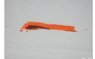 |
| cadmiun yellow + burnt Sienna | x4.5 | 120 | 440 | 50 | 160 | 100 | 140 | - |  |
|
| cadmiun orange | x3.5 | - | - | - | - | 80 | 160 | - |  |
|
| cadmiun yellow | x4.5 | 130 | 350 | - | - | 60 | 160 | - | ||
References
- Webb, K.; Herrero-Cortell, M.À.; Picollo, M. (Eds.) Multiband Imaging Techniques with Silicon-Based Sensors; Conservation 360º; 2025; Vol. IV. [Google Scholar]
- Herrero-Cortell, M.Á.; Raïch, M.; Artoni, P.; Madrid-García, J.A. Caracterización de pigmentos históricos a través de técnicas de imagen, en diversas bandas del espectro electromagnético. Ge-Conservación 2022, 22, 58–75. [Google Scholar] [CrossRef]
- Vila Espuña, A.; Izzo, F.C.; Herrero-Cortell, M.A.; Picollo, M.; Davanzo, E.; García-Castillo, A.M.; Fuster-López, L. It's not what it seems! A selection of degradation phenomena in modern black oil painting. In Science and Art IX: Sciences and Technologies Applied to Heritage Conservation; Ministry of Culture and Sport: Madrid, 2023; pp. 247–261. [Google Scholar]
- Rauca, A.; Ghervase, L.; Berdie, A.; Agachi, M. Unveiling the secrets of an artwork through non-invasive investigations—Case study of a 19th-century female portrait. Minerals 2023, 13, 1193. [Google Scholar] [CrossRef]
- Cucci, C.; Picollo, M.; Vervat, M. Trans-illumination and trans-irradiation with digital cameras: Potentials and limits of two imaging techniques used for the diagnostic investigation of paintings. J. Cult. Herit. 2012, 13, 83–88. [Google Scholar] [CrossRef]
- Keller, A.T.; Lenz, R.; Artesani, A.; Mosca, S.; Comelli, D.; Nevin, A. Exploring the ultraviolet induced infrared luminescence of titanium white pigments. In UV-Vis Luminescence Imaging Techniques; Picollo, M., Stols-Witlox, M., Fuster-López, L., Eds.; Editorial Universitat Politècnica de València: Valencia, 2019; pp. 201–232. [Google Scholar] [CrossRef]
- Cosentino, A.; Gil, M.; Ribeiro, M.; Di Mauro, R. Technical photography for mural paintings: The newly discovered frescoes in Aci Sant’Antonio (Sicily, Italy). Conservar Patrim. 2014, 20, 23–33. [Google Scholar] [CrossRef]
- Webb, K.; Summerour, R.; Giaccai, J. A case study using multiband and hyperspectral imaging for the identification and characterization of materials on archaeological Andean painted textiles. In Textile Group Postprints; American Institute for Conservation of Historic and Artistic Works: Washington, DC, 2014. [Google Scholar]
- Herrero-Cortell, M.A.; Creus, M.R.; Artoni, P.; Puig, I. Multi-band technical imaging in the research of the execution of paintings: The case study of the portrait of Carlos IV, by Francisco de Goya. Ge-Conservación 2018, 14, 5–15. [Google Scholar] [CrossRef]
- Cosentino, A. Practical notes on ultraviolet technical photography for art examination. Conservar Patrim. 2015, 21, 53–62. [Google Scholar] [CrossRef]
- Dyer, J.; Verri, G.; Cupitt, J. Multispectral Imaging in Reflectance and Photo-induced Luminescence Modes: A User Manual; The British Museum: London, 2013. [Google Scholar]
- Picollo, M.; Stols-Witlox, M.; Fuster-López, L. (Eds.) UV-Vis Luminescence: Imaging Techniques; Polytechnic University of Valencia: Valencia, 2019; Vol. 1. [Google Scholar] [CrossRef]
- Warda, J. The AIC Guide to Digital Photography and Conservation Documentation, 3rd ed.; Foundation of the American Institute for Conservation of Historic and Artistic Works: Washington, DC, 2017. [Google Scholar]
- Warda, J. The AIC Guide to Digital Photography and Conservation Documentation, 2nd ed.; Foundation of the American Institute for Conservation of Historic and Artistic Works: Washington, DC, 2011. [Google Scholar]
- Cosentino, A.; Stout, S. Photoshop and multispectral imaging for art documentation. e-Preserv. Sci. 2014, 11, 91–98. [Google Scholar]
- Cosentino, A. Infrared technical photography for art examination. e-Preserv. Sci. 2016, 13, 1–6. [Google Scholar]
- Herrero-Cortell, M.À.; Artoni, P.; Raïch, M.; Aliaga, J.; Puig, I. Looking through the layers: Transmitted infrared photography (IRT) applied to the technical and documentary study of paintings on canvas. Ge-Conservación 2021, 19, 62–73. [Google Scholar] [CrossRef]
- Herrero-Cortell, M.A.; Artoni, P.; Raïch, M. Transmitted light imaging in VIS and IR in the study of paintings: A brief report on the behaviour of the main historical pigments. Cult. Sci. Colore–Colour Cult. Sci. 2020, 12, 79–88. [Google Scholar] [CrossRef]
- Artoni, P.; Raïch, M.; Bertelli, L.; Puig, I.; Herrero-Cortell, M. Exploring the possibilities of false color infrared transmission imaging. In Multiband Imaging Techniques with Silicon-Based Sensors; Webb, K.; Herrero-Cortell, M.; Picollo, M., Eds.; Conservation 360º, Vol. IV; 2025.
Figure 1.
Diagram of the configuration of the four mock-ups prepared.
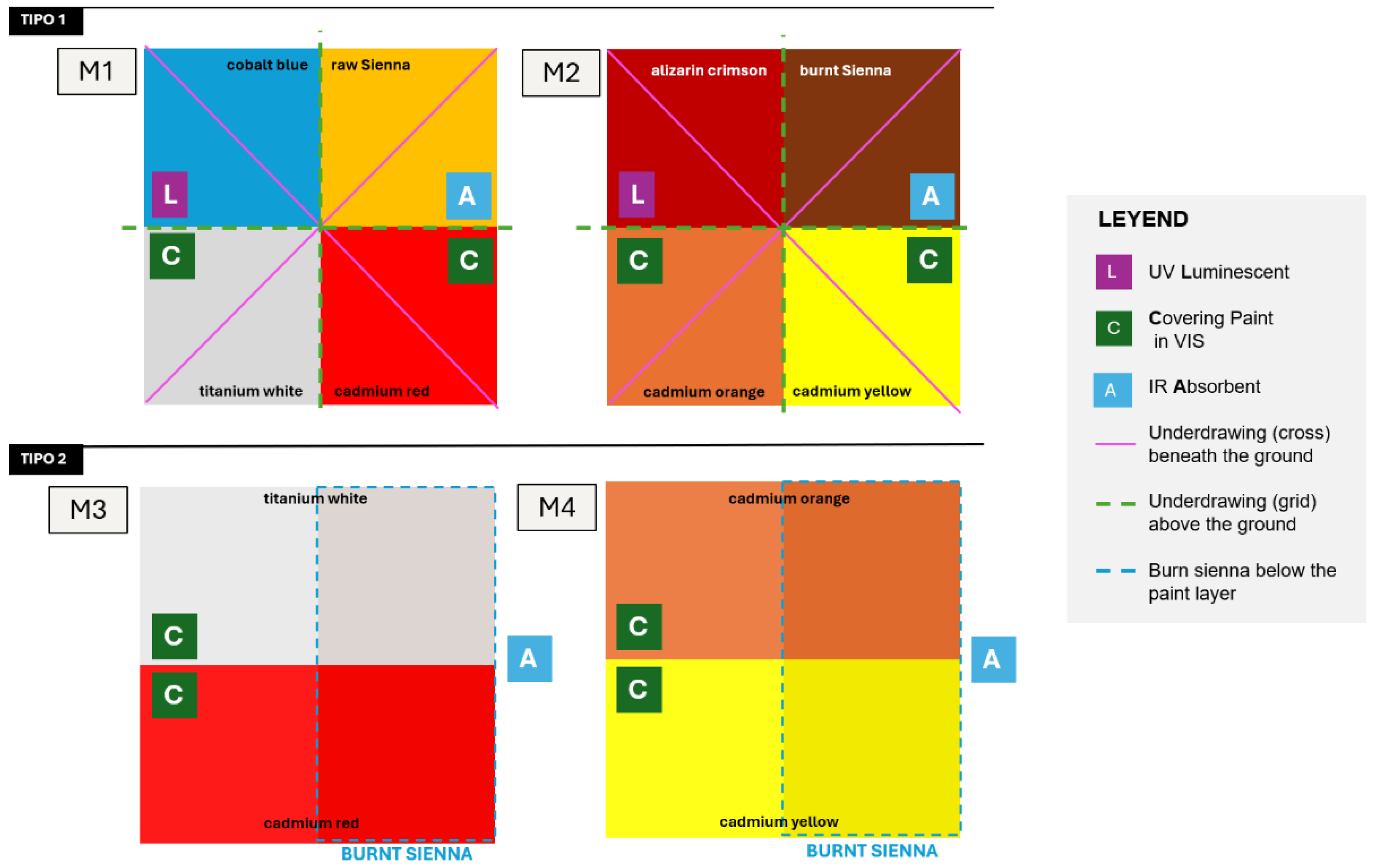
Figure 2.
(a) MBI analysis of mock-ups mounted on a die-cut foam board (b) µMBI of each mock-Up.
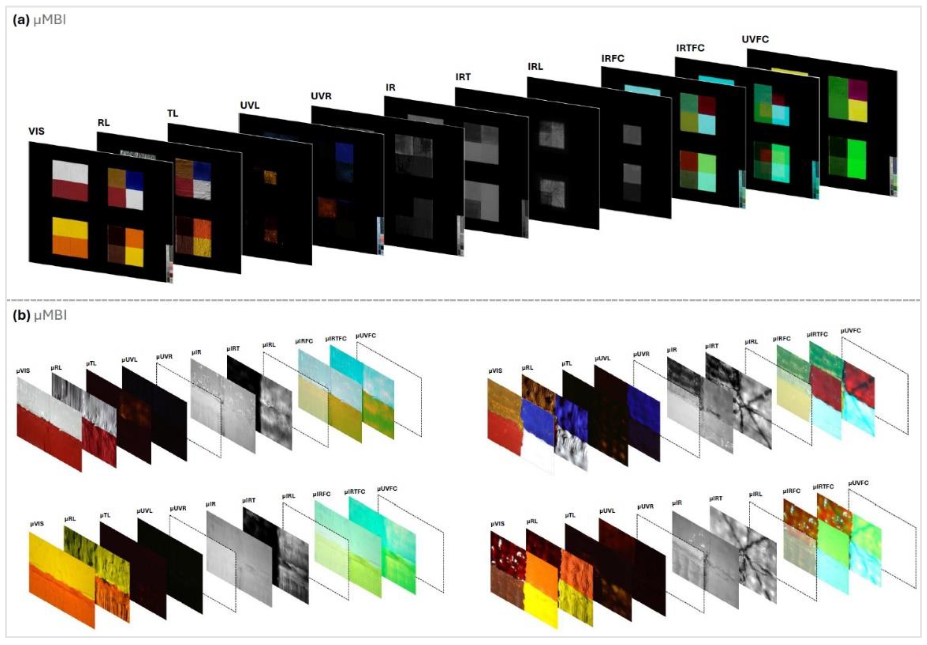
Figure 3.
Composition of the four images using visible light μVIS (M1, M2, M3 and M4), with the smaller images corresponding to each mock-up in standard MBI on both sides.
Figure 3.
Composition of the four images using visible light μVIS (M1, M2, M3 and M4), with the smaller images corresponding to each mock-up in standard MBI on both sides.
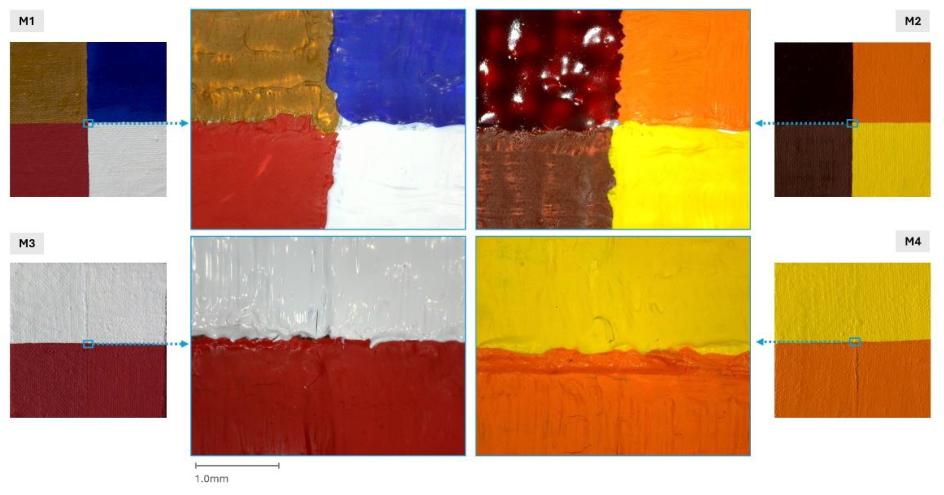
Figure 4.
Composition of the four images μIR (M1, M2, M3 and M4), with the smaller images corresponding to each mock-up in standard MBI on both sides. Bottom left, the reference of the VIS image.
Figure 4.
Composition of the four images μIR (M1, M2, M3 and M4), with the smaller images corresponding to each mock-up in standard MBI on both sides. Bottom left, the reference of the VIS image.
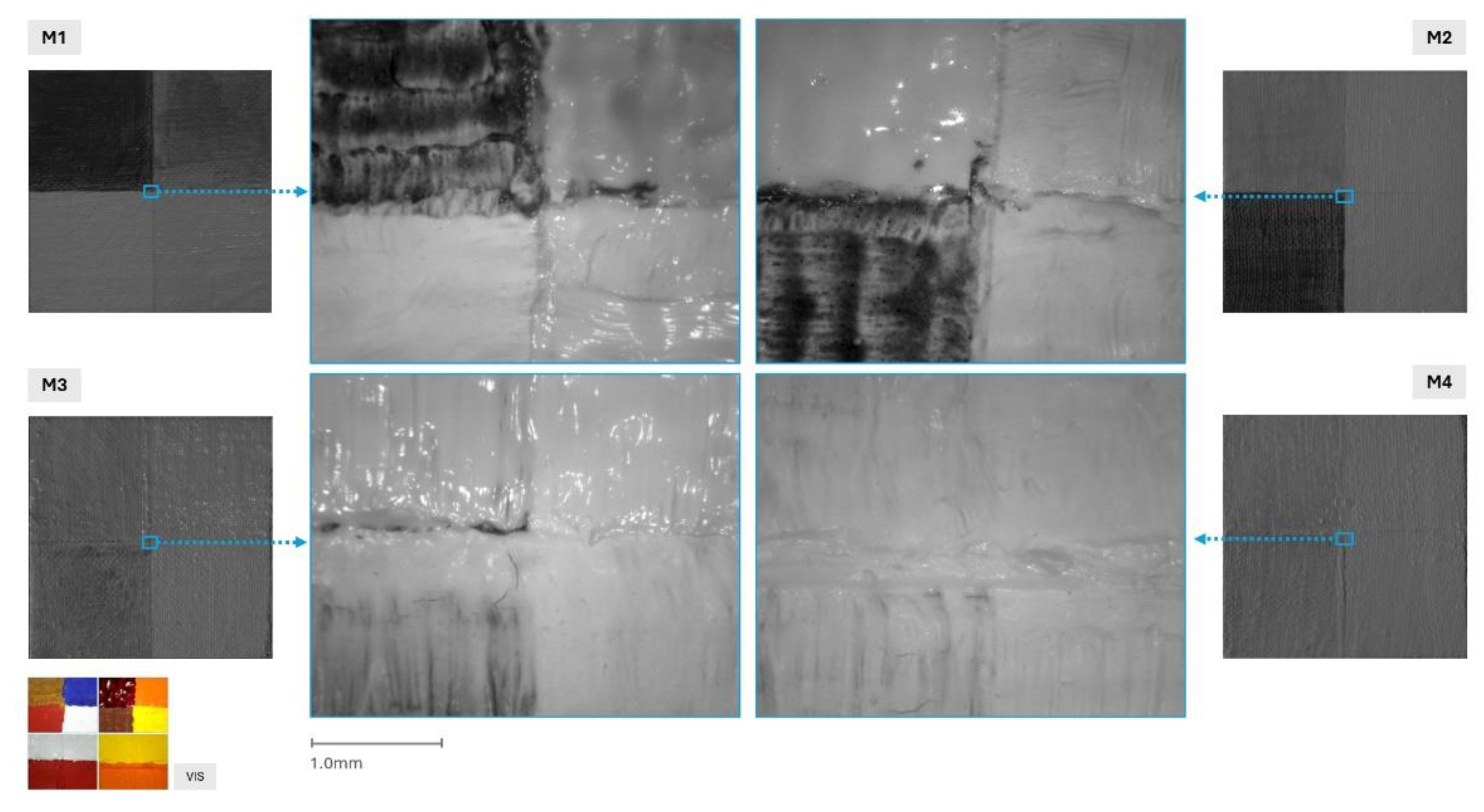
Figure 5.
Composition of the four μRL images (M1, M2, M3 and M4), with the images corresponding to each mock-up in standard MBI on both sides.
Figure 5.
Composition of the four μRL images (M1, M2, M3 and M4), with the images corresponding to each mock-up in standard MBI on both sides.
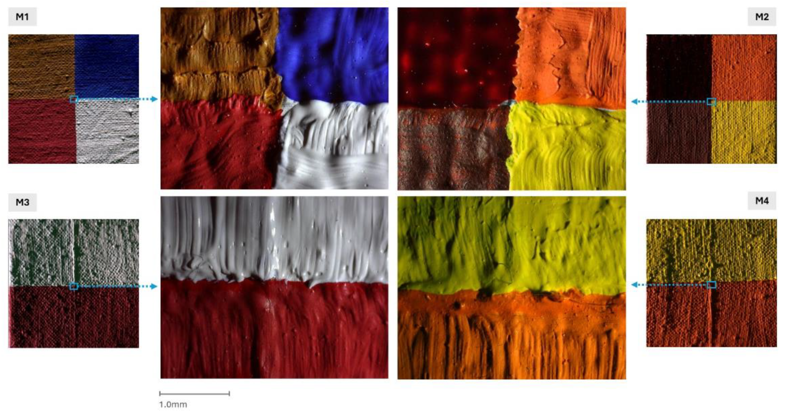
Figure 6.
Composition of the four μTL images (M1, M2, M3 and M4). The images, on the sides correspond to each mock-up captured using standard MBI. Bottom left, reference of VIS image.
Figure 6.
Composition of the four μTL images (M1, M2, M3 and M4). The images, on the sides correspond to each mock-up captured using standard MBI. Bottom left, reference of VIS image.
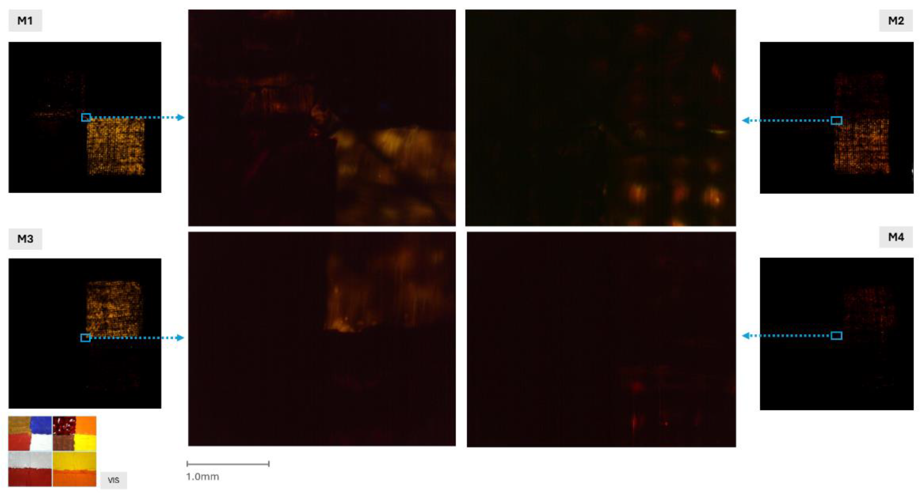
Figure 7.
Composition of the four IRT images (M1, M2, M3 and M4), with the corresponding standard MBI images for each mock-up displayed alongside. Bottom left, reference VIS image.
Figure 7.
Composition of the four IRT images (M1, M2, M3 and M4), with the corresponding standard MBI images for each mock-up displayed alongside. Bottom left, reference VIS image.
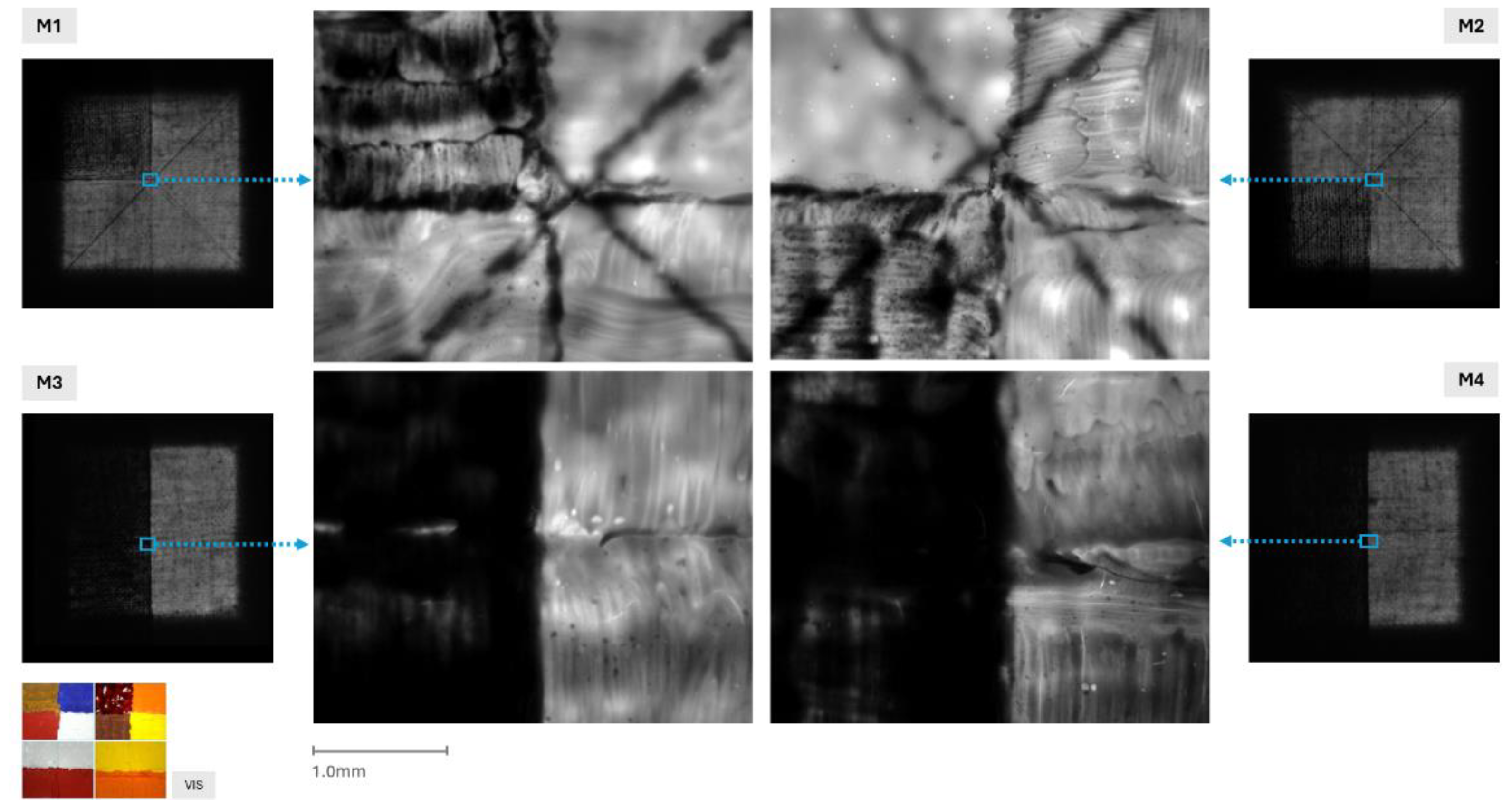
Figure 8.
Composition of the four images UVL (M1, M2, M3 and M4), with the smaller images corresponding to each mock-up in standard MBI on the sides. Bottom left, reference of VIS image.
Figure 8.
Composition of the four images UVL (M1, M2, M3 and M4), with the smaller images corresponding to each mock-up in standard MBI on the sides. Bottom left, reference of VIS image.
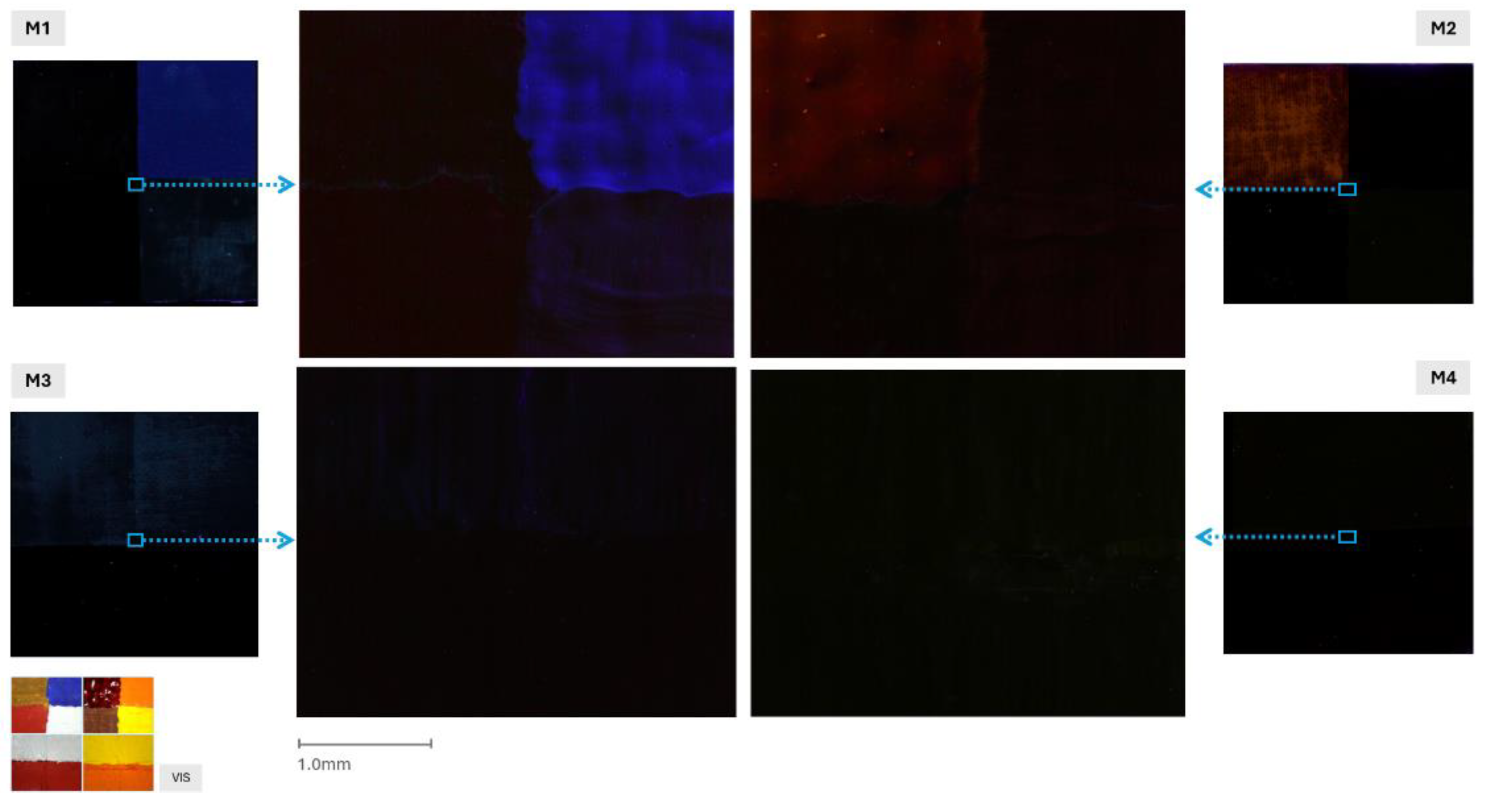
Figure 9.
Composition of the four images µIRFC (M1, M2, M3 and M4), with the images corresponding to each mock-up in standard MBI on the sides. Bottom left, reference of VIS image.
Figure 9.
Composition of the four images µIRFC (M1, M2, M3 and M4), with the images corresponding to each mock-up in standard MBI on the sides. Bottom left, reference of VIS image.
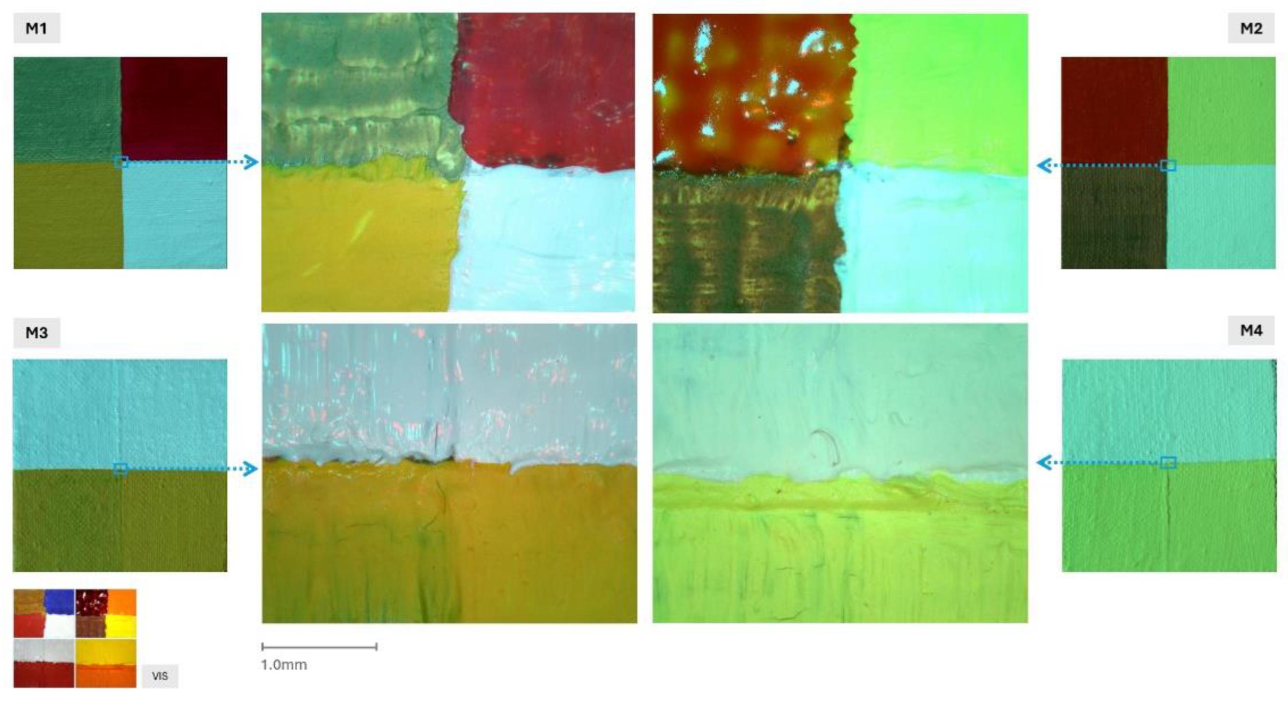
Figure 10.
Composition of the four images μIRTFC (M1, M2, M3 and M4), with the images corresponding to each mock-up in standard MBI on the sides. Bottom left, reference of VIS image.
Figure 10.
Composition of the four images μIRTFC (M1, M2, M3 and M4), with the images corresponding to each mock-up in standard MBI on the sides. Bottom left, reference of VIS image.
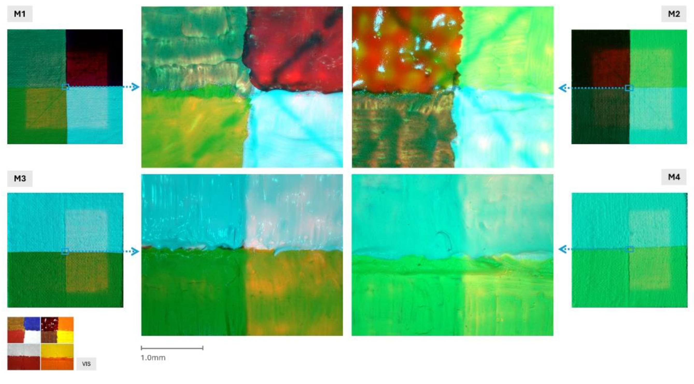
Table 1.
The paint used in the study was selected according to the oil paint provided by Golden Artist Colours, Inc. The following characteristics have been selected for the study: micromultiband analysis in the visible (VIS), ultraviolet (UV) and infrared (IR) bands [2].
Table 1.
The paint used in the study was selected according to the oil paint provided by Golden Artist Colours, Inc. The following characteristics have been selected for the study: micromultiband analysis in the visible (VIS), ultraviolet (UV) and infrared (IR) bands [2].
| Type | Test tube | Oil Paint | Specific characteristics in VIS, UV and IR | ||||
|---|---|---|---|---|---|---|---|
| Non-opaque VIS | VIS opaque | UV luminescent | Transparent IR | IR absorbent | |||
| 1 | M1 | cobalt blue | X | X | X | ||
| raw Sienna | X | X | |||||
| titanium white | X | X | |||||
| cadmium red | X | X | |||||
| M2 | alizarin crimson | X | X | X | |||
| burnt Sienna | X | X | |||||
| cadmium orange | X | X | |||||
| cadmium yellow | X | X | |||||
| 2 | M3 | titanium white | X | X | |||
| cadmium red | X | X | |||||
| burnt Sienna | X | X | |||||
| M4 | cadmium orange | X | X | ||||
| cadmium yellow | X | X | |||||
| burnt Sienna | X | X | |||||
Table 2.
Equipment used for µMBI image capture.
| Microscope | Image | Acronym |
|---|---|---|
| AM4113ZT | Visible microphotography | µVIS |
| Raking light micrography | µRL | |
| Transillumination microphotography | µTL | |
| Ultraviolet-induced luminescence visible microphotography | µUVL | |
| AD4113T-12V | Infrared microphotography | µIR |
| Infrared transirradiation micrograph | µIRT | |
| AM4113ZT + AD4113T-12V | False-colour infrared microphotography | µIRFC |
| False-colour infrared transirradiation microphotography | µIRTFC |
Note: AM4113ZT and AD4113T-12V correspond to Dino-Lite microscope models (AnMo Electronics Corp., Taiwan).
Table 3.
Methodology followed in the study with regard to lighting conditions.
| Microscope | Image | Microscope mode | External illumination | Lighting geometry |
|---|---|---|---|---|
| AM4113ZT | µVIS | Power | - | Front |
| µRL | Off | LED torch | Tangential | |
| µTL | Off | LED torch | Rear | |
| µUVL | Off | (2) UV torch | 45º bracket | |
| AD4113T-12V | µIR | On in IR mode | - | Front |
| µIRT | Off | IR torch | Rear |
Disclaimer/Publisher’s Note: The statements, opinions and data contained in all publications are solely those of the individual author(s) and contributor(s) and not of MDPI and/or the editor(s). MDPI and/or the editor(s) disclaim responsibility for any injury to people or property resulting from any ideas, methods, instructions or products referred to in the content. |
© 2025 by the authors. Licensee MDPI, Basel, Switzerland. This article is an open access article distributed under the terms and conditions of the Creative Commons Attribution (CC BY) license (http://creativecommons.org/licenses/by/4.0/).
Copyright: This open access article is published under a Creative Commons CC BY 4.0 license, which permit the free download, distribution, and reuse, provided that the author and preprint are cited in any reuse.


