
Submitted:
29 October 2025
Posted:
30 October 2025
You are already at the latest version
Abstract
Efficient, high-frequency collection of environmental data is crucial for real-time monitoring and automated management in smart livestock settings. However, existing RS485-based polling method has limitations. Therefore, in this study, a parallel Message Queuing Telemetry Transport (MQTT)-based communication structure was designed for multisensory structures. The proposed system enables the broker to send messages simultaneously from distributed sensor nodes and uses a topic-based hierarchical structure to ensure scalability and processing efficiency. The structure’s performance was experimentally tested using three scenarios: changing the node count, changing the transmission interval, and comparing communication methods. The proposed MQTT structure showed superior performance to RS485 in terms of the mean latency (98 ms vs 178 ms), message reception success rate (99.2% vs 94.5%), processing rate (1.33 msg/s vs 0.67 msg/s), and communication error frequency (1.3 errors/1000 trials vs 5.7 errors/1000 trials). In addition the topic-based message structure was shown to enable dynamic scalability with diverse environmental sensors. This study empirically demonstrated the utility and stability of an MQTT-based communication structure in a smart livestock setting that requires high-frequency data collection. These findings could be used as foundational technology for intelligent automated livestock implementations.
Keywords:
MQTT-based communication
; smart livestock monitoring
; high-frequency environmental sensing
; parallel communication
; IoT
; sensor network
1. Introduction
Recent advances in smart livestock technology include systems capable of precisely monitoring and automatically controlling the livestock rearing environment. This has further highlighted the importance of technology for high-frequency collection and processing of diverse environmental data, including temperature, humidity, ammonia (NH3), and carbon dioxide (CO2) data. In high-density rearing environments, automation of ventilation and cooling or detection of abnormal conditions is directly related to improvements in livestock welfare and productivity; therefore, the construction of high-frequency real-time sensors for data collection and stable communication infrastructure is considered a core element of smart livestock systems [1].
However, most commercial livestock environmental control systems use RS485-based serial communication methods, which create problems when sending data from multiple sensors simultaneously, such as collisions between nodes, data delays, and limited scalability. The RS485 hardware structure itself operates using a single master-multiple slave arrangement, and in a multiple node environment, it depends on serial polling, which creates a communication bottleneck as the number of sensors increases [2,3].
To solve these problems, smart agriculture research has increasingly focused on the lightweight messaging protocol Message Queuing Telemetry Transport (MQTT), which is based on a publish-subscribe model, because this protocol is capable of reducing interference between sensor nodes and distributing network load through asynchronous communication [4]. When extending a parallel communication structure, MQTT can minimize latency and ensure real-time performance even in a high-frequency data collection environment.
In this study, to overcome problems caused by communication bottlenecking, an MQTT-based parallel communication structure was designed and applied to smart livestock housing. The performance of the proposed structure was analyzed experimentally and compared with the performance of an RS485-based structure, with a focus on communication delays, data collection success rates, and system load. The proposed structure consists of ESP32-based sensor nodes and a Jetson TX-based broker system. By quantifying the change in performance under increases in the number of sensors, the utility of its parallel communication design was demonstrated.
The remainder of this paper is ordered as follows. In Section 2, prior studies are discussed, and in Section 3, the core architecture of the system design and parallel structure are described. In Section 4, the implementation process and experimental setting are described, and in Section 5, the results and analysis are presented. Finally, in Section 6, the technological significance and limitations of this study are discussed and directions for future research are suggested.
2. Related Work
Environmental monitoring technology for smart livestock housing has been developed to improve productivity and livestock welfare by collecting environmental data, such as the temperature, humidity, NH3, and CO2 conditions and linking these data with an automated control system [5].
Initially, single-point monitoring with analog sensors was used for smart livestock housing. However, various Internet of Things (IoT) structures are being introduced based on multiple nodes with digital sensors. The communication structure of these systems is usually constructed using an RS485-based wired approach [6].
RS485-based communication systems are highly reliable technology that has been widely used in various industrial fields. However, in a smart livestock housing environment, where a large number of sensory nodes are operating simultaneously, the serial polling method can lead to communication delays, data collisions, and structural scalability limitations [7]. For this reason, studies have started focusing on various wireless communication methods and lightweight communication protocols.
One representative example is the MQTT protocol, which provides advantages such as high compatibility with small IoT devices, reduced bottlenecks between nodes due to its broker-based publish-subscribe structure, improved transmission efficiency, and low energy consumption. Based on these properties, MQTT has been rated as highly applicable to various aspects of smart farms, including smart livestock housing and smart greenhouses [8]. In particular, the quality of service (QoS) settings, asynchronous transmission structure, and topic-based routing function of MQTT are considered suitable for high-frequency data collection environments [9].
A previous study proposed a system to collect and send temperature, humidity, and illuminance data to a central server in real-time and analyzed the basic structure implementation and communication stability [10]. However, this study was mostly limited to single nodes or small-scale sensor environments. Moreover, only a few studies have analyzed changes in communication performance with increasing node count, determined whether a parallel structure can minimize delays, or quantitatively compared the performance of MQTT and RS485.
To bridge these gaps in the literature, this study proposes a high-frequency MQTT communication architecture for smart livestock housing that consists of multisensor nodes with a parallel structure. In addition, the performance of the system was analyzed experimentally by comparison with an existing RS485 system, with a focus on communication delays, data collection success rates, and system load. Thus, this study aimed to empirically demonstrate the structural scalability and potential to resolve communication bottlenecks of MQTT-based systems.
3. System Design and Architecture
3.1 Summary of the System Components
The proposed system was designed to enable the parallel collection of real-time data from multisensor nodes in a smart livestock housing environment, which requires high-frequency environmental data collection. As shown in Figure 1, the whole system can be divided into three main components.
The multisensor nodes consist of temperature, humidity, NH3, and CO2 sensors attached to an ESP 32-based microcontroller board. Each sensor node measures data independently, and the data are published to the MQTT broker at regular intervals.
The broker is a Mosquitto-based MQTT broker built on a Jetson TX board, and it receives messages published by each sensor node asynchronously.
The database (DB)/cloud storage and control system stores messages received from the broker on an analytical server or DB and is responsible for subsequent processing for eventual linkage with a control system.
For the hardware composition of the system, as depicted in Figure 1, all sensor nodes are connected to the broker via Wi-Fi-based wireless communication.
Direct communication does not occur between sensor nodes, and the broker acts as a mediator that handles the flow of all messages based on the MQTT protocol.
3.2. Design of the Parallel MQTT Communication Structure
At the core of the proposed system is the design of the MQTT structure, which enables each sensor node to send data in parallel using a unique topic. For example, each sensor is defined within the following topic system:
- /env/temp/1: temperature from Node 1;
- /env/hum/1: humidity from Node 1;
- /env/co2/2: CO2 from Node 2;
- /env/nh3/2: NH3 from Node 2.
In this way, data from each sensor are separated based on the topic, and the broker can process messages in parallel without data collisions between sensors.
Message publishing is set at the QoS 1 level to ensure the reliability of the environmental data by guaranteeing that each message would be delivered at least once [11].
Inside the node, sensing data processing and publishing are implemented in a non-blocking manner based on FreeRTOS to minimize bottlenecks in each sensor node.
3.3. JSON Message Format and Communication Flow
The MQTT message payload was constructed based on the JSON format, as shown in Figure 2. Messages are generated regularly within the nodes and then filtered and stored after being received by the broker.
The overall flow of communication, as depicted in Figure 3, is as follows: data are measured by sensor nodes and then a JSON message is generated, published by topic, received by the broker, and then stored and processed.
Due to the parallel structure, the broker can simultaneously receive data from multiple sensors.
4. Implementation and Experimental Environment Configuration
4.1. Hardware Configuration
To implement the parallel MQTT communication structure, the hardware configuration listed in Table 1 was used.
The ESP32 board operates independently via a USB power supply and is capable of parallel testing using up to 8 nodes, thereby providing headroom for increasing the number of sensors. The complete hardware configuration and communication methods between nodes are summarized in Figure 4. This configuration shows the actual connections and direction of data flow between the sensor nodes, broker, and storage.
The hardware configuration of the smart livestock housing environmental monitoring system and structure of MQTT-based communication links are presented in Figure 4. All sensor nodes are based on an ESP32 microcontroller board. They measure environmental data, such as temperature, humidity, CO2, and NH3, and publish the data to the broker at regular intervals. Each node publishes directly to the broker via a Wi-Fi-based wireless connection, and the system is designed to enable transmission of messages in parallel. Therefore, communication interference does not occur between nodes in this process.
The sensor nodes publish data using unique topic paths, and the broker identifies the topics, receives the messages in real-time, and stores them in local storage (SQLite DB). Unlike RS485-based serial communication methods, this structure enables scalable flow of communication without additional latency, even if the number of sensors is increased.
In addition, the broker can be linked to a real-time dashboard or other control systems based on the data it receives. Therefore, this structure is applicable as a scalable structure that integrates data collection, processing, and control. Moreover, it can be used as a reference architecture for parallel high-frequency sensor communication that can be applied to actual smart livestock housing in the field.
4.2. Software Environment and MQTT Configuration
4.2.1. MQTT Broker and Message Processing Settings
The sensor node software was developed based on the Arduino ESP32 platform, and FreeRTOS was chosen for the operating system to implement multitasking-based data measurement and publishing processes. Each sensor node collects sensor data independently, and these data are regularly published to the broker using the MQTT protocol. Here, data collection and delivery are run as separate tasks to minimize the effects on the sensing cycle and network status.
Sensing data are measured at a fixed interval of every 2 s, and each message is constructed in JSON format with a UTC timestamp. An example of a JSON message is shown in Figure 2.
The broker and client are both built with a non-blocking network programming structure to enable real-time parallel processing of high-frequency messages from the multisensory nodes. The MQTT S/W configuration is presented in Table 2.
The MQTT communication components and major settings are summarized in Table 2. Each configuration parameter was selected by considering the stability and low latency of data delivery and feasibility of the parallel processing structure in a high-frequency messaging environment.
For the broker software, the open-source Eclipse Mosquitto v2.0 was chosen as the optimal structure for lightweight message processing. The broker is installed on a Jetson TX2 running the Ubuntu 18.04 operating system to provide sufficient performance for processing messages published simultaneously by the multisensory nodes.
The QoS level is set to 1 to ensure that each message was delivered to the broker at least once and reduce the risk of overloading the broker. Message topics are constructed in the form /env/[sensor_type]/[node_id] to enable identification of the sensor type and node. This topic structure supports broker- and subscriber-side parallel filtering and processing of the messages.
All messages are sent in JSON format with UTF-8 encoding. Accurate timestamps are included alongside the sensor data so that the collected data can be arranged in a time series.
The overall flow of communication is implemented in an asynchronous, non-blocking manner to enable real-time processing without queuing delay, even when messages are received in parallel from up to eight sensor nodes. The received messages are stored in a local SQLite database and include metadata, such as the message size and time of receipt, for use in the quantitative performance analysis.
4.2.2. Message Topic Structure and Sensor Scalability
The system proposed in this study was designed to enable parallel collection of diverse environmental data by topic based on an MQTT-based communication structure.
The message topic structure adheres to the form /env/[sensor_type]/[node_id], where sensor_type is the environmental variable being measured (e.g., temperature, humidity, CO₂, and NH3) and node_id is a unique identifier for the sensor node. This structure allows the broker to classify received messages by topic and can prevent bottlenecks in the data flow because the subscriber can selectively receive sensor topics [13].
For example, /env/temp/1 indicates temperature data measured at Node 1, while /env/co2/3 indicates CO2 concentration data measured at Node 3.
In this study, the following four major livestock housing environmental variables were recorded: temperature, humidity, CO2, and NH3. However, the system is extendible and can measure variables such as fine dust (PM2.5), volatile organic compounds (VOCs), illuminance (Lux), noise (dB), atmospheric pressure (hPa), water supply (L/h), water temperature (°C), and GPS coordinates [14].
Table 3 lists examples of MQTT topics for different environmental variables that might be measured in smart livestock housing.
This system appears to be suitable not only for real-time monitoring but also for time series data collection for future analysis. Because each topic is constructed in JSON format, the messages can easily be parsed and processed by a wide range of clients.
This structure is highly versatile and can be extended without separate structural changes for future refinement of smart livestock housing systems, new environmental sensor addition, or monitoring in specific regions.
4.3. Experimental scenario construction
To test the performance of the parallel MQTT-based smart livestock housing communication structure proposed in this study, three experimental scenarios were devised [15] to evaluate the system’s core design elements: communication bottlenecks, node scalability, and data collection stability. In addition, the scenarios were designed to be performed repeatedly with the same hardware and network environment.
4.3.1. Scenario 1: Analysis of Latency and Data Collection Rate with Increasing Node Count
This scenario was designed to verify whether the performance of the parallel structure declined when the sensor node count increases. Each node sends data independently to the MQTT broker, and the data reception success rate and latency are measured based on whether these data are processed normally by the broker.

Table 4.
Scenario 1: Performance evaluation according to the number of sensor nodes.
| Category | Details |
| Objective | Evaluate changes in data reception rate and latency as the number of sensor nodes increases |
| Main Variable | Number of sensor nodes: 2, 4, 6, 8 |
| Controlled Conditions | Fixed transmission interval of 2 s; same sensor types (temperature, humidity, CO₂) |
| Evaluation Metrics | Data reception success rate (%), average and maximum latency (ms) |
| Significance | Assess the scalability and performance stability of the parallel MQTT communication architecture |
Each sensor node individually sends temperature, humidity, and CO2 data to the MQTT at 2 s intervals, and these data are received in real-time by the broker.
By measuring the reception success rate and the mean latency, this experiment determines whether the communication structure can maintain a stable performance even in a high-density environment.
4.3.2. Scenario 2: Analysis of System Stability at Different Transmission Intervals
This scenario was designed to investigate whether the system can process data in a stable manner when the message transmission interval changes. The number of nodes is fixed at 6 while the transmission interval varies between 1 s and 10 s. Each node includes temperature, humidity, CO2, and NH3 sensors, and all nodes send data to the MQTT broker according to the selected interval [16].
The broker’s ability to process the message queue, message loss rate, and processing speed are measured to determine the minimum acceptable transmission interval in a real-time environment and evaluate the limits of the system’s stability. This experiment focuses on detecting potential data loss and processing delays when several messages are sent simultaneously each second.
Table 5.
Scenario 2: System stability evaluation according to the transmission interval.
| Category | Details |
| Objective | Evaluate system stability and message loss rate under different transmission intervals |
| Main Variable | Transmission interval: 1 s, 2 s, 5 s, 10 s |
| Controlled Conditions | Fixed number of sensor nodes (6 nodes); identical sensor types (temperature, humidity, CO₂, NH₃) |
| Evaluation Metrics | Message loss rate (%), message throughput (messages/sec), average processing delay |
| Significance | Analyze the broker's stability and performance threshold in a real-time communication environment |
4.3.3. Scenario 3: Performance Comparison of the MQTT vs RS485 Communication Structures
RS485 is a wired serial communication structure that is widely used at many livestock facilities in the field, while MQTT is a broker-based asynchronous communication structure with advantages in terms of network scalability and real-time processing. In this scenario, the same sensors (temperature, humidity, CO2) are connected to each communication protocol and data are collected under the same environmental conditions [17].
The transmission interval is kept constant at 3 s. RS485 uses polling with a master-slave structure, while MQTT uses a publish/subscribe approach. The data loss rate, mean latency, and frequency of communication errors are measured and compared between the two systems.
Figure 5 and Figure 6 depict the differences in communication flow between the proposed MQTT-based structure and conventional RS485-based structure [18].
The MQTT structure uses a publish/subscribe-based asynchronous communication model. When each sensor node sends data to the central broker, the broker relays the messages to subscribers based on topics.
This structure ensures independence between nodes and allows the broker to effectively process data sent from multiple nodes in parallel, thus providing excellent scalability and processing flexibility. Meanwhile, RS485 uses a master-slave-based serial communication structure in which the master uses polling to collect data from each slave node in series.
Although this structure has the advantages of configurational simplicity and reliability, it has limited scalability and presents a risk of polling delays and communication collisions when the number of nodes is increased. Table 6 compares the technical differences between the MQTT and RS485 communication structures.
5. Results and Performance Analysis
5.1. Configuration of the Experimental Environment
To test the performance of the proposed system, the parallel MQTT communication structure was implemented in a real environment and subjected to three experimental scenarios, including a comparison with the RS485-based structure. The conditions for the experimental environment are shown in Table 7.
The experiments were performed in a realistically sized smart livestock facility testbed, and repeated measurements were recorded under each condition to improve the reliability of the data. The network configuration, node count, and sensor composition were varied depending on the scenario, and the communication latency, message success rate, and message throughput were used as the main evaluation metrics.
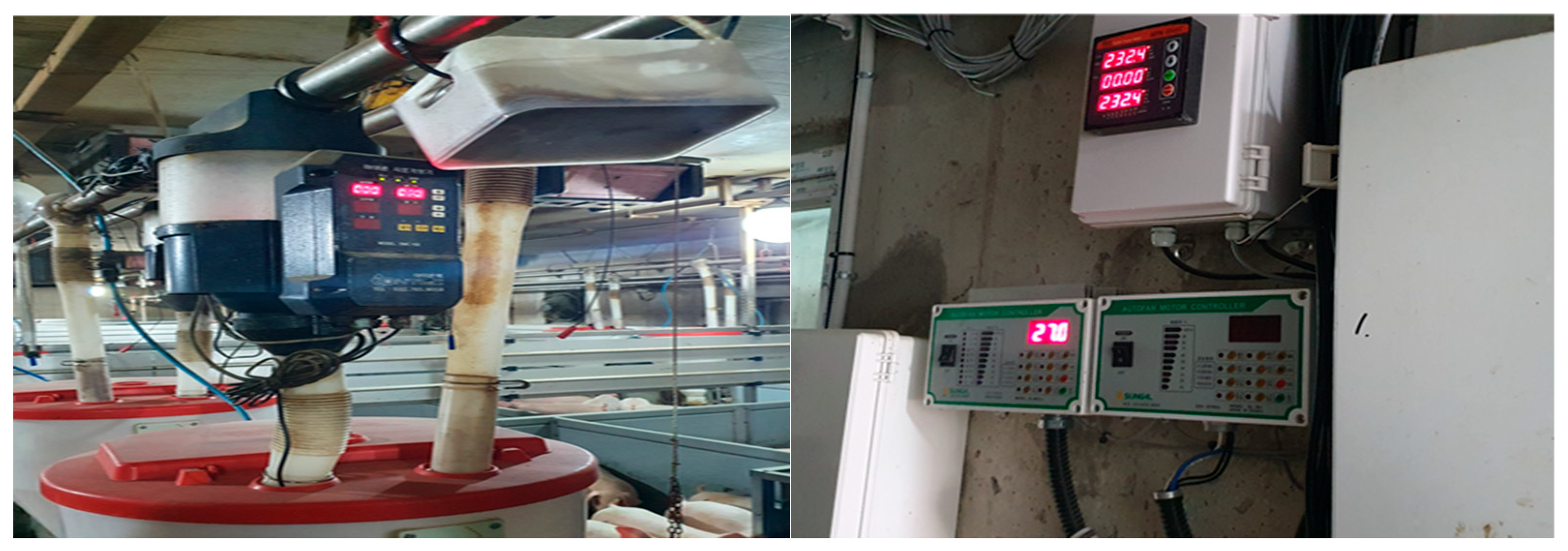
Figure 6.
Photos of the RS485 and MQTT equipment installed in Suncheon City.
5.2. Scenario 1: Performance Analysis with Increasing Node Count
The purpose of this scenario was to quantitatively analyze the changes in communication performance of the MQTT-based structure when the number of sensor nodes was increased. The experiment was conducted while sequentially increasing the number of nodes from 2 to 8, and the following indices were measured under each condition [19]:
- Message success rate (%);
- Average latency (ms);
- Throughput (msg/s).
For each condition, measurements were recorded in triplicate in the same environment, and the mean values were calculated. The transmission interval was fixed at 3 s, and the QoS level was set to 1. The measured results are shown in the graphs below (Figure 7, Figure 8 and Figure 9).
Figure 7 shows the change in message reception success rate with increasing sensor node count. From 2 to 6 nodes, a high mean success rate of over 98% was maintained, although the value declined slightly in the configuration with 8 nodes (96.2%), which may have been related to the instantaneous load when the MQTT broker tried to process multiple published requests simultaneously. However, an overall QoS 1 level of reliability was maintained, and this performance still satisfied the collection accuracy criterion (95%) required for real smart livestock facilities.
Figure 8 shows the trend in communication latency with increasing node count. As the node count increased, the broker’s overall queue waiting time became longer and a gentle increase in latency was observed. The average latency was 32 ms in the 2-node configuration and increased up to 118 ms in the 8-node configuration. Due to the nature of the MQTT protocol, message processing priority is not guaranteed; therefore, some delay is inevitable at times of focused traffic. Nevertheless, the latency in all conditions was within the acceptable range (<500 ms) for real-time livestock facilities.
Figure 9 shows the message throughput over unit time (msg/s) as the node count varied. With the transmission interval fixed at 3 s, a linear increase in throughput was observed with increasing node count. This means that the parallel MQTT structure exhibited stable performance with no data collection bottlenecks, even in a multi-node environment. Because the system is designed so that each node publishes independently to the broker, efficient distributed processing of the data was possible without interference between nodes.
In summary, the proposed parallel MQTT-based communication structure maintained a high message reception success rate and acceptable latency even when the node count was increased, and the message throughput also showed a linearly increasing pattern. This demonstrates empirically that this structure is an effective scalable communication architecture that can simultaneously ensure communication stability and real-time operations in an environment such as smart livestock housing when the sensor node count gradually increases.
5.3. Scenario 2: Performance Analysis at Different Transmission Intervals
The purpose of this scenario was to analyze changes in system stability and data processing performance when the sensor transmission interval was decreased. The number of nodes was fixed at 4, and the transmission cycle was set to either 1 s, 3 s, 5 s, or 10 s. In each condition, the following variables were measured [20]:
- Message loss rate (%);
- Average latency (ms);
- Throughput (msg/s).
Figure 10 shows the change in message loss rate when the sensor transmission interval was changed between 1 s and 10 s. At the 1 s transmission interval, the average loss rate was 4.2% due to saturation of the message queue, thus revealing the limitations of the broker processing throughput. Meanwhile, at transmission intervals of 3 s or more, the loss rate remained less than 1%, while at transmission intervals of 5 s or more, practically no loss was observed. These results suggest that setting an appropriate transmission interval is an important factor for ensuring system stability.
Figure 11 shows the trend in average communication latency when the transmission cycle varied. As the transmission interval became shorter, simultaneous processing demand on the broker became concentrated, and a clear increase in the message queue processing latency was observed. At a transmission interval of 1 s, the average latency was 145 ms, which is a 3.6-fold increase compared to the latency of 40 ms at a transmission interval of 10 s. Nevertheless, the latency was below 200 ms at all transmission intervals, which satisfies the criterion (500 ms) for real-time operation in smart livestock housing.
Figure 12 shows the change in message throughput per second (msg/s) with varying transmission intervals. As expected, shorter transmission intervals increased the throughput, and the maximum throughput recorded at the 1 s transmission interval was approximately 4.0 msg/s. This means that the system is capable of rapidly processing multiple messages. Nonetheless, the loss rate and latency must be considered alongside the increased throughput. Therefore, in real applications of this system, rather than simply maximizing the throughput, the optimal transmission cycle must be set based on ensuring stability and acceptable latency.
To summarize, the proposed MQTT-based structure maintained a stable loss rate and latency at transmission intervals of 3 s or more, and system stability was also confirmed under the high-frequency transmission condition. This demonstrates that the structure allows for flexible balancing of communication efficiency and real-time performance by adjusting the transmission interval depending on the environment.
5.4. Scenario 3: Performance comparison between the MQTT-based and RS485-based systems
The purpose of this scenario was to directly compare the communication performance between the proposed MQTT-based structure and a conventional RS485-based method by empirically testing the technical strengths and limitations of each approach. Both systems were implemented in the same smart livestock housing and included the same number of sensor nodes (4) and transmission interval (3 s). During the experiment, the following variables were measured in triplicate and compared:
- Average latency (ms);
- Message success rate (%);
- Throughput (msg/s);
- Communication error frequency.
Figure 13 shows a comparison of the average latency between the MQTT and RS485 systems. While MQTT recorded a low average latency of 98 ms, RS485 showed a latency of approximately 178 ms. RS485 uses serial polling based on a single communication bus, meaning that it has an inherent structural limitation of increasing response time as the number of nodes increases. On the other hand, the MQTT-based structure allows each node to publish to the broker in parallel, which is advantageous for real-time data processing.
Figure 14 shows a comparison of the message success rates between the two methods. MQTT recorded an average message reception success rate of 99.2%, thus demonstrating 4.7% higher reliability than RS485 (94.5%). RS485-based communication was sensitive to external interference, such as line noise, data collisions, and timeouts, whereas MQTT was capable of more stable message reception due to the TCP-based retransmission mechanism and QoS setting.
Figure 15 shows a comparison of the number of messages that could be processed per unit time. MQTT showed a throughput of 1.33 msg/s, while RS485 showed a throughput of 0.67 msg/s, meaning that the throughput of MQTT was approximately twice as high as that of RS485. The high throughput of the MQTT-based system is due to the asynchronous structure, which allows each node to send messages to the broker independently. This is an important factor in environments that require sensor multiplexing.
The MQTT-based structure only recorded 1.3 errors on average, while the RS485-based structure recorded a higher error frequency of 5.7. RS485 likely suffered from more errors due to problems such as timeouts and address collisions in the master-slave structure. Conversely, MQTT showed robust error restoration based on the publish-subscribe protocol.
In summary, the proposed MQTT-based communication structure showed superior performance to RS485 in all metrics and showed especially clear differences in terms of real-time performance, reliability, and processing efficiency. This demonstrates empirically that the MQTT structure is highly suitable for environments that require high-frequency data collection from multiple sensors, such as smart livestock housing.
6. Discussion
In this study, a parallel MQTT-based communication structure was designed and its communication performance was quantitatively compared with that of a conventional RS485-based approach in a smart livestock housing environment. In the experiments, the MQTT-based system demonstrated superior performance to the RS485-based system in all key indices, including latency, message reception success rate, message throughput, and communication error frequency. In this section, the technical significance and practical implications of these findings are discussed and future applications and directions for improvement are suggested.
6.1. Technical Significance and Effects
6.1.1. Performance Improvement Due to Communication Parallelization
Compared with RS485, the proposed MQTT-based structure allows each sensor node to independently publish messages to the broker, meaning that performance was not significantly impaired even when the node count was increased.
This demonstrates that the parallel architecture is suitable for a multisensory environment and offers advantages in terms of throughput and scalability.
6.1.2. QoS-Based Reliability
The QoS setting in the MQTT protocol maintained the data loss rate below 1%, and the TCP-based communication characteristics showed a stable structure that is robust to noise.
6.1.3. Flexible Message Structure and Sensor Scalability
Defining the topic structure in the form /env/[sensor_type]/[node_id] facilitated the addition of diverse sensors and tracing of the message flow. Thus, this structure provides important benefits in terms of system maintenance and recovery as well as operating efficiency.
6.2. Field Applications and Practical Implications
This study was based on communication experiments conducted in a real smart livestock housing testbed, meaning that in addition to verifying the theoretical design, the field applicability of the proposed approach was also ensured. Moreover, by testing the integrative performance across different scenarios, such as increasing node count and varying transmission interval, and performing comparisons with other types of communication structures, this study provides an important reference point for the application of this system to real smart livestock facilities.
6.3. Limitations and Directions for Future Improvements
Although the experimental results revealed the excellent performance of the proposed parallel MQTT-based communication structure across several measures, the scope of the study and experimental conditions present certain limitations. These limitations must be accounted for in future real-world implementations of the system to ensure its applicability to large-scale livestock facilities. Technical limitations and specific improvement plans are presented in Table 8.
7. Conclusions
In this study, a parallel MQTT-based communication structure was designed to efficiently collect high-frequency data from multiple sensors in smart livestock housing. The performance of this structure in a real environment was compared with that of the conventional RS485-based approach.
The proposed system was designed to maintain stable message reception performance even when the number of sensor nodes increased or transmission interval decreased. Experiments were conducted to measure major outcomes related to latency, message reception success rate, message throughput, and communication stability.
In terms of latency, the MQTT-based system demonstrated excellent real-time performance, with a response time that was over 45% shorter on average than that of RS485. The reception success rate of MQTT was over 99%, demonstrating high reliability. Due to its parallel structure, the throughput of MQTT was twice as efficient as that of RS485, which suggests that this system would be vastly advantageous in environments with sensor multiplexing. Finally, the communication error frequency of MQTT was 75% lower than that of RS485.
These results demonstrate that the proposed communication structure is a feasible option for high-frequency, multisensory-based smart livestock facilities. They also reveal the potential of the system for use in cutting-edge agricultural information and communication technology systems, which demand real-time performance and scalability.
Notably, this study was limited to experiments in a single-broker environment; therefore, further experiments will be needed to reflect different QoS settings, packet structure, and changes in network quality.
In conclusion, this study presents a practical foundation for refining communication structures in smart livestock housing environments. Future technical extensions and empirical studies will transform this approach into a key component for intelligent automation at smart livestock facilities.
Funding
This work was supported by Korea Institute of Planning and Evaluation for Technology in Food, Agriculture and Forestry (IPET) and Korea Smart Farm R&D Foundation (KosFarm) through Smart Farm Innovation Technology Development Program, funded by Ministry of Agriculture, Food and Rural Affairs (MAFRA) and Ministry of Science and ICT (MSIT), Rural Development Administration(RDA) (RS-2024-00406426)
Institutional Review Board Statement
Not applicable.
Informed Consent Statement
Not applicable.
Data Availability Statement
The data presented in this study are not publicly available due to operational restrictions but are available from the corresponding author upon reasonable request.
Conflicts of Interest
The authors declare no conflicts of interest.
Abbreviations
The following abbreviations are used in this manuscript:
QoS Quality of service
IoT Internet of Things
MQTT Message Queuing Telemetry Transport
P2P Point to point
References
- Wolfert, S.; Ge, L.; Verdouw, C.; Bogaardt, M.J. Big Data in Smart Farming – A Review. Agric. Syst. 2017, 153, 69–80. [Google Scholar] [CrossRef]
- Muthu, J.R.; Thimmaraj, K.; Sasikala, S.J. Live Temperature Monitoring System Using MQTT. In Proceedings of the 2024 International Conference on Intelligent and Innovative Technologies in Computing, 2024, Electrical and Electronics (IITCEE); pp. 20–24.
- Setyawan, D.Y.; Warsito, W.; Marjunus, R.; Sumaryo, S. A Novel Controlling System for Smart Farming-based Internet of Things (IoT). International Journal of Advanced Computer Science & Applications 2024, 15, 630–641. [Google Scholar]
- Baek, J.; Kanampiu, M.W. A MQTT-Based Soil Moisture Level Notification System for a Smart Farm. In Proceedings of the 2021 IEEE 4th International Conference on Power and Energy Applications (ICPEA), 2021; pp. 126–130. [Google Scholar]
- Hunkeler, U.; Truong, H.L.; Stanford-Clark, A. MQTT-S—A publish/subscribe protocol for wireless sensor networks. In Proceedings of the 2008 3rd International Conference on Communication Systems Software and Middleware (COMSWARE 2008), Bangalore, India, 6–10 January 2008; pp. 791–798. [Google Scholar]
- Naik, N. Choice of effective messaging protocols for IoT systems: MQTT, CoAP, AMQP, and HTTP. In Proceedings of the 2017 IEEE International Systems Engineering Symposium (ISSE), Vienna, Austria, 11–13 October 2017; pp. 1–7. [Google Scholar] [CrossRef]
- Banks, A.; Briggs, E.; MQTT Version 5. 0. OASIS Standard. 2019. Available online: https://docs.oasis-open.org/mqtt/mqtt/v5.0/mqtt-v5.0.html (accessed on 7 August 2025).
- Donzia, S.K.Y.; Kim, H. Architecture Design of a Smart Farm System Based on Big Data Appliance Machine Learning. In Proceedings of the 2020 20th International Conference on Computational Science and Its Applications (ICCSA), 2020; pp. 45–52. [Google Scholar]
- Safitri, N.A.; Priambodo, A.S. MQTT and CoAP Communication Protocol Analysis in Internet of Things System for Strawberry Hydroponic Plants. Journal of Robotics, Automation, and Electronics Engineering 2023, 1, 45–56. [Google Scholar] [CrossRef]
- Grgić, K.; Špeh, I.; Heđi, I. A Web-Based IoT Solution for Monitoring Data Using MQTT Protocol. In Proceedings of the 2016 International Conference on Smart Systems and Technologies (SST), Osijek, Croatia; 2016; pp. 249–253. [Google Scholar]
- Naik, N. Choice of Effective Messaging Protocols for IoT Systems: MQTT, CoAP, AMQP and HTTP. In 2017 IEEE International Systems Engineering Symposium (ISSE); Vienna, Austria, 11–13 Oct 2017; pp. 1–7.
- Nuratch, S. Applying the MQTT Protocol on Embedded System for Smart Sensors/Actuators and IoT Applications. In Proceedings of the 2018 15th International Conference on Electrical Engineering/Electronics, Computer, 2018, Telecommunications and Information Technology (ECTI-CON); pp. 628–631.
- Ayaz, M.; Ammad-Uddin, M.; Sharif, Z.; Mansour, A.; Aggoune, E.H.M. Internet-of-Things (IoT)-Based Smart Agriculture: Toward Making the Fields Talk. IEEE Access 2019, 7, 129551–129583. [Google Scholar] [CrossRef]
- Marques, G.; Pitarma, R. An Indoor Monitoring System for Ambient Assisted Living Based on IoT Architecture. Int. J. Environ. Res. Public Health 2016, 13, 1152. [Google Scholar] [CrossRef] [PubMed]
- Jiang, P.; Xia, H.; He, Z.; Wang, Z. Design of a Water Environment Monitoring System Based on Wireless Sensor Networks. Sensors 2009, 9, 6411–6434. [Google Scholar] [CrossRef] [PubMed]
- Khasawneh, H.J.; Al Asbahi, R.; Alzariqi, A.W.; Al Qada, D.R.; Bujuk, A.; Nawfal, M.A.; Tareen, M. Industrial IoT-Based Submetering Solution for Real-Time Energy Monitoring. Discover Internet of Things 2025, 5, 15. [Google Scholar] [CrossRef]
- Thangavel, D.; Ma, X.; Valera, A.; Tan, H.-X.; Tan, C.K.-Y. Performance Evaluation of MQTT and CoAP via a Common Middleware. In Proceedings of the 2014 9th IEEE International Conference on Intelligent Sensors, Sensor Networks and Information Processing (ISSNIP), Singapore, 21–24 April 2014; pp. 1–6. [Google Scholar]
- Thangavel, D.; Ma, X.; Valera, A.; Tan, H.P.; Tan, C.K.Y. Performance Evaluation of MQTT and CoAP via a Common Middleware. In Proceedings of the 2014 IEEE Ninth International Conference on Intelligent Sensors, Sensor Networks and Information Processing (ISSNIP), Singapore, 21–24 April 2014; pp. 1–6. [Google Scholar] [CrossRef]
- Vakili, M.; Ghamsari, M.; Rezaei, M. Performance Analysis and Comparison of Machine and Deep Learning Algorithms for IoT Data Classification. arXiv arXiv:2001.09636, 2020. [CrossRef]
- Bauer, J.; Aschenbruck, N. Design and Implementation of an Agricultural Monitoring System for Smart Farming. In Proceedings of the 2018 IoT Vertical and Topical Summit on Agriculture (IOT Tuscany), Tuscany, Italy, 8–9 May 2018; pp. 1–6. [Google Scholar]
Figure 1.
Overall system architecture for parallel Message Queuing Telemetry Transport (MQTT)--based environmental data collection in smart livestock housing. DB: database; Temp: temperature; Humi: humidity.
Figure 1.
Overall system architecture for parallel Message Queuing Telemetry Transport (MQTT)--based environmental data collection in smart livestock housing. DB: database; Temp: temperature; Humi: humidity.
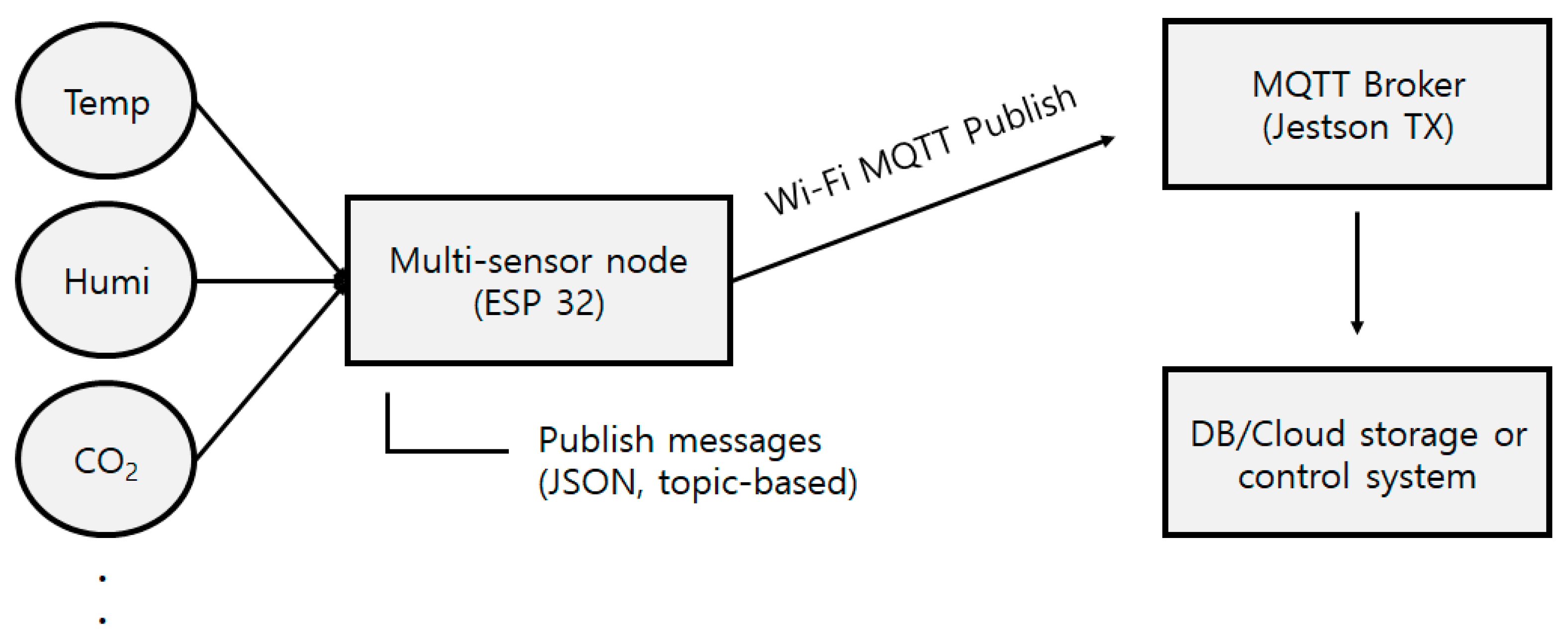
Figure 2.
Example of the JSON format in the MQTT message payload
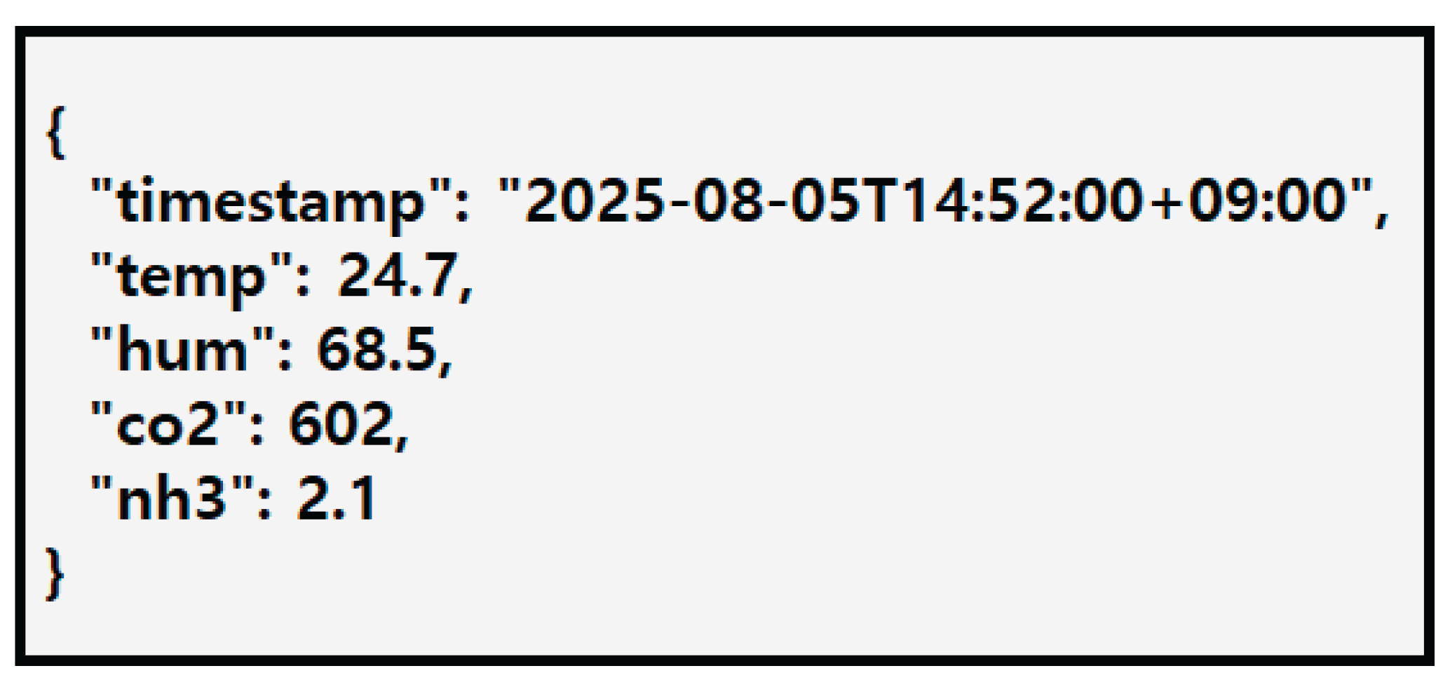
Figure 3.
End-to-end communication flow of environmental data from sensor nodes to storage and control systems in the proposed parallel MQTT-based architecture. QoS: quality of service.
Figure 3.
End-to-end communication flow of environmental data from sensor nodes to storage and control systems in the proposed parallel MQTT-based architecture. QoS: quality of service.
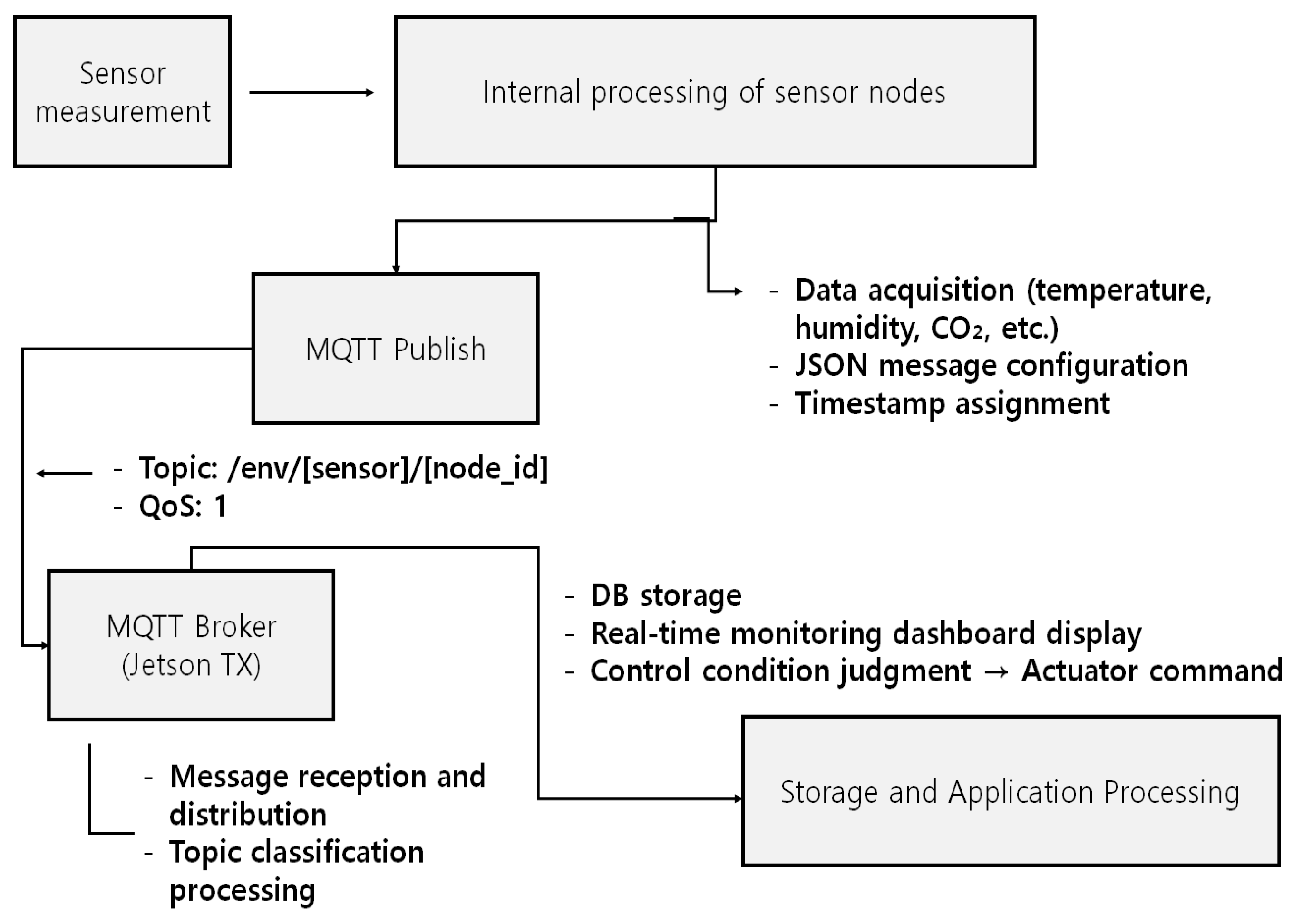
Figure 4.
Hardware configuration and MQTT-based communication topology for multisensory smart livestock monitoring.
Figure 4.
Hardware configuration and MQTT-based communication topology for multisensory smart livestock monitoring.
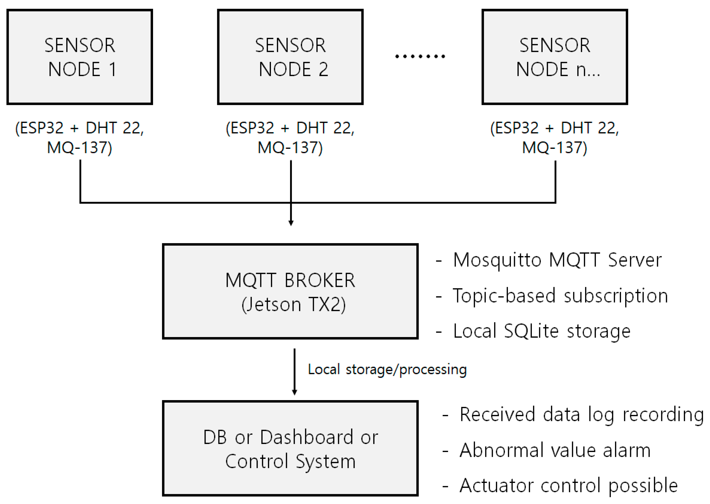
Figure 5.
MQTT communication structure flowchart.
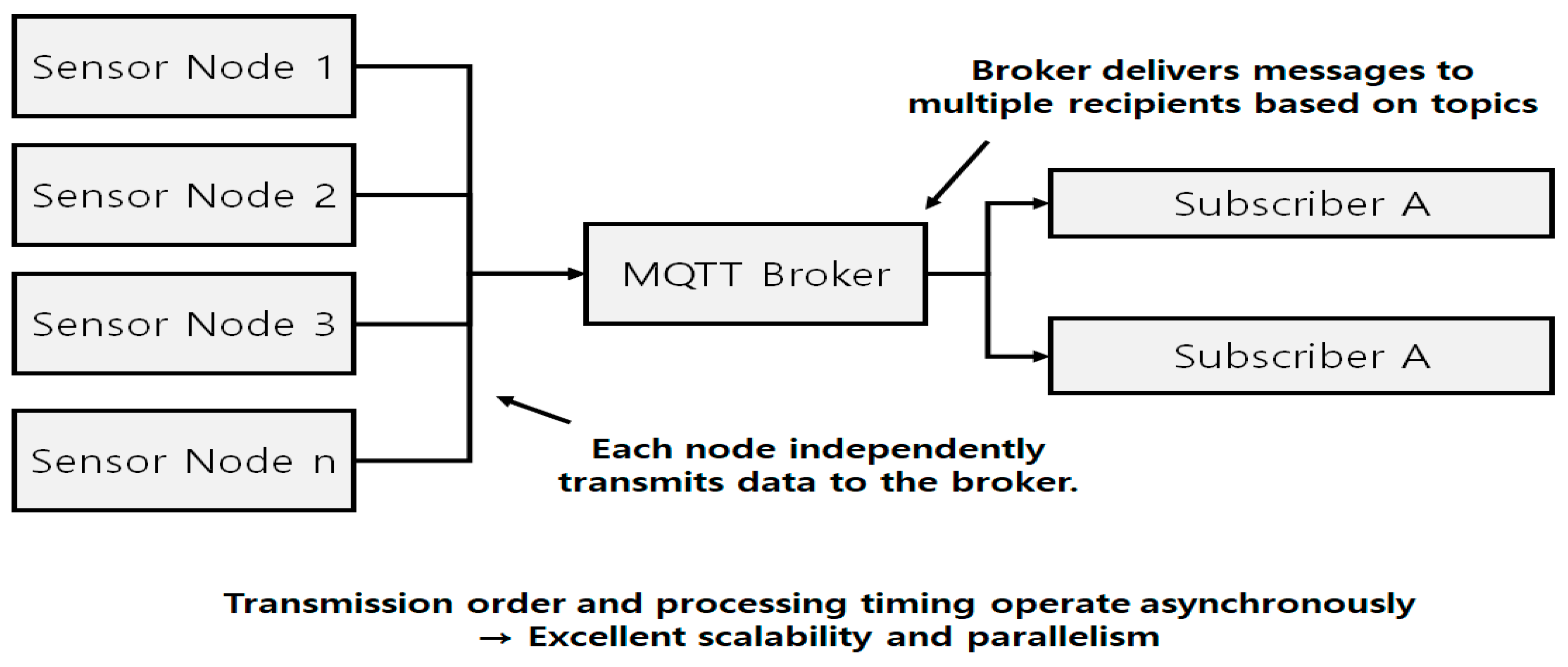
Figure 6.
RS485 communication structure flowchart.
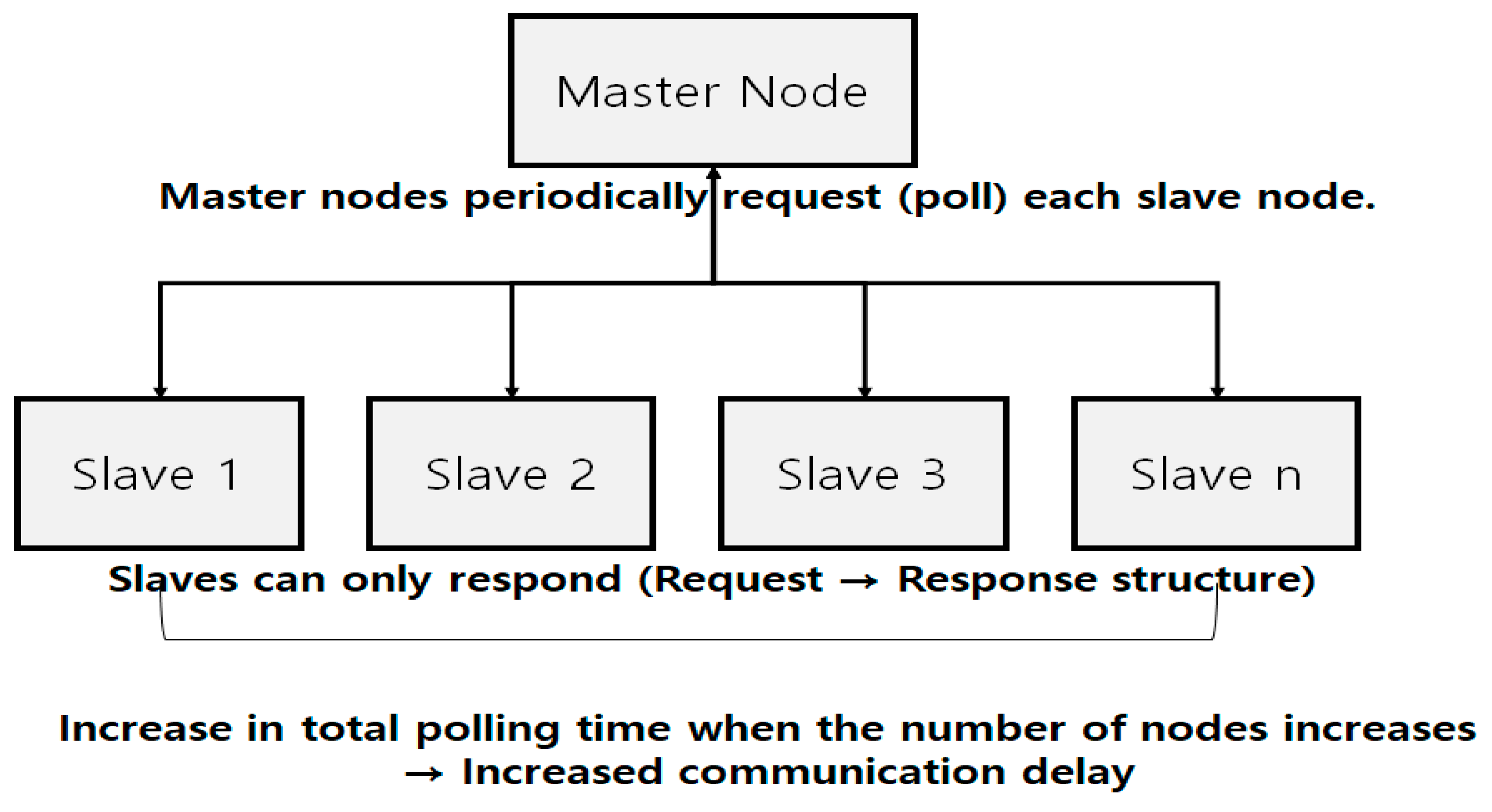
Figure 7.
Message success rate vs number of nodes.
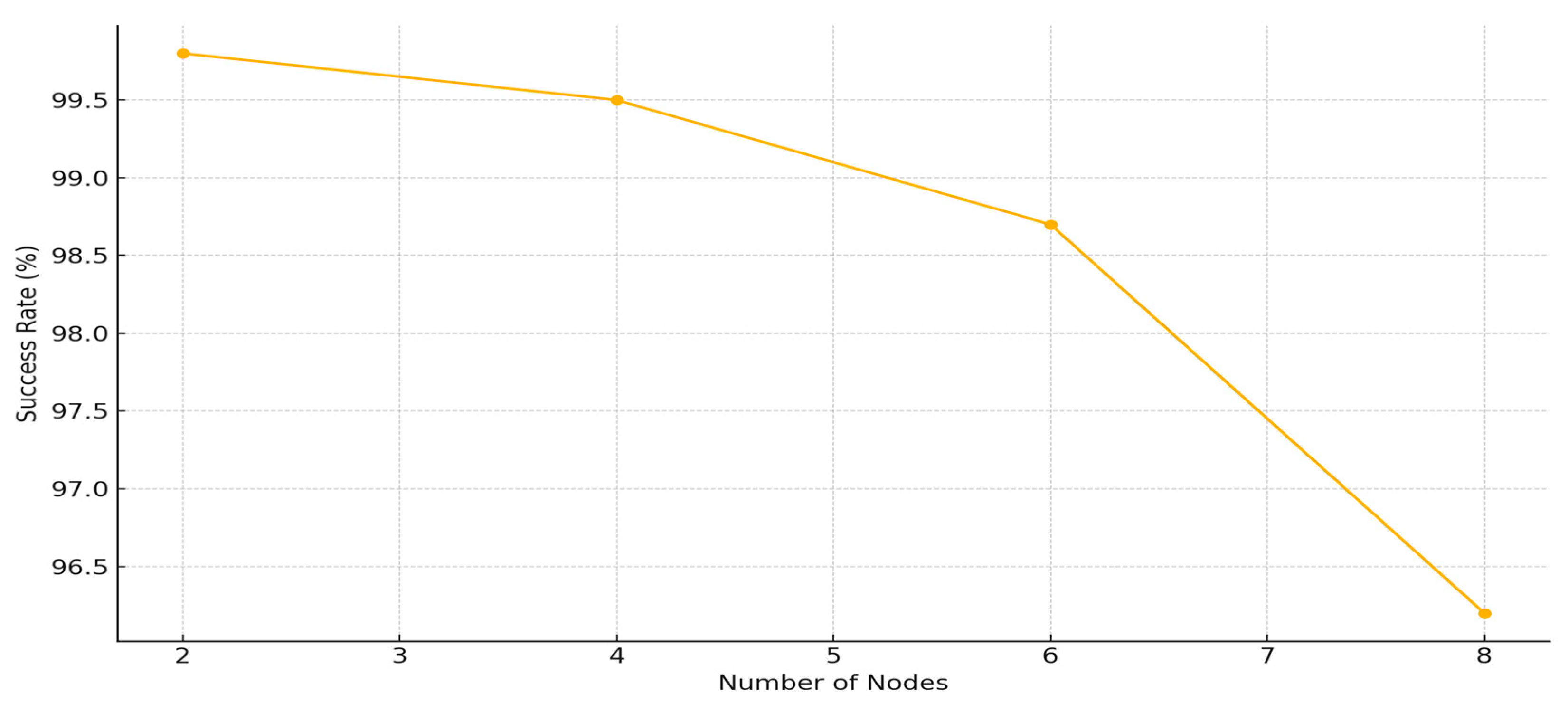
Figure 8.
Average latency vs number of nodes.
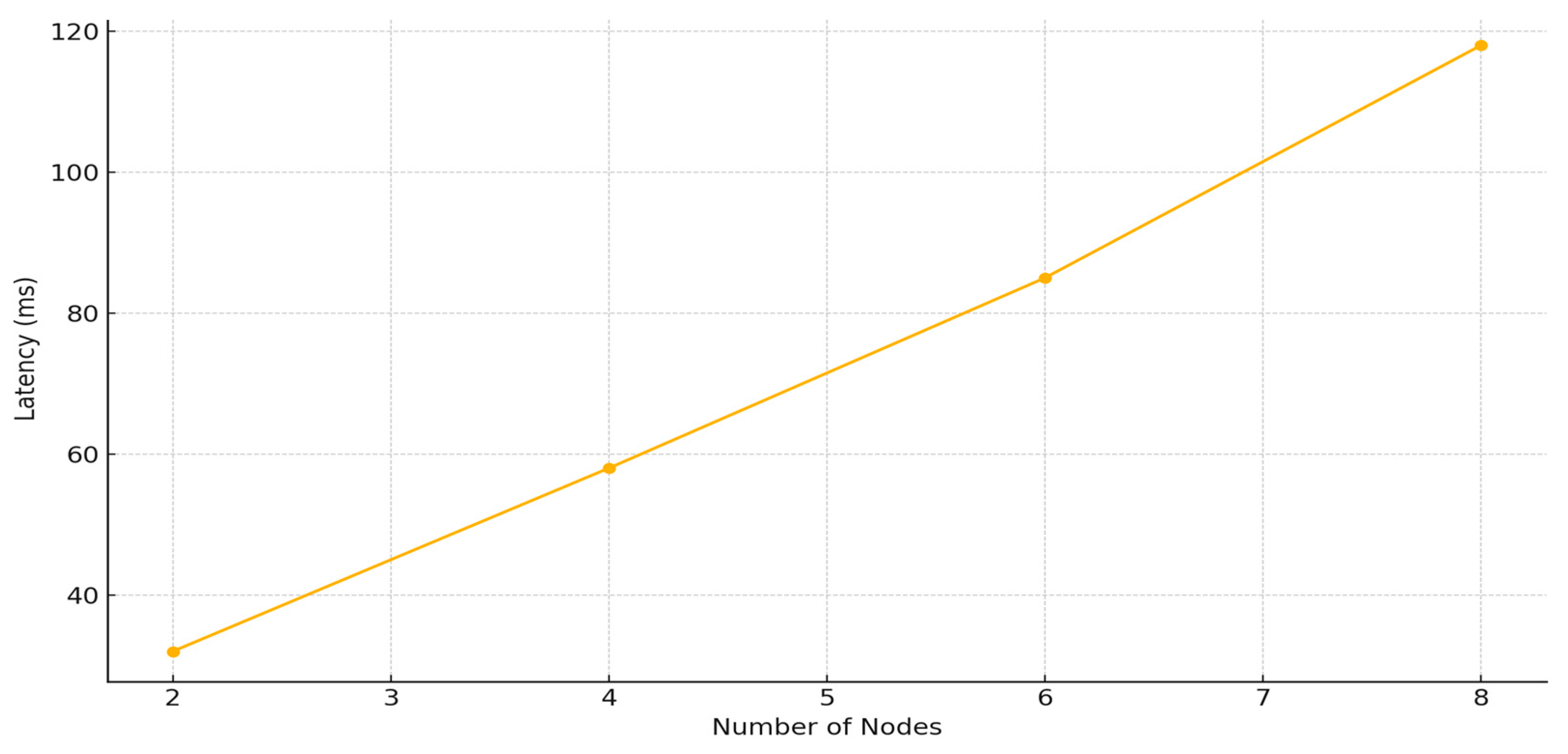
Figure 9.
Message throughput vs number of nodes.
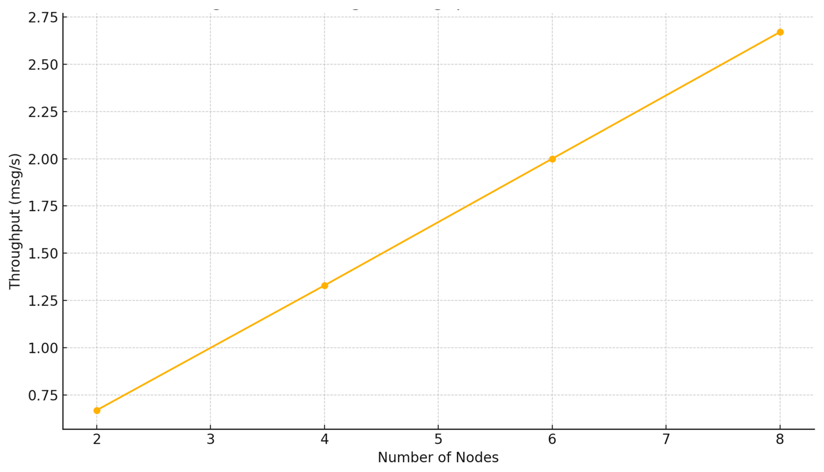
Figure 10.
Message loss rate vs transmission interval.
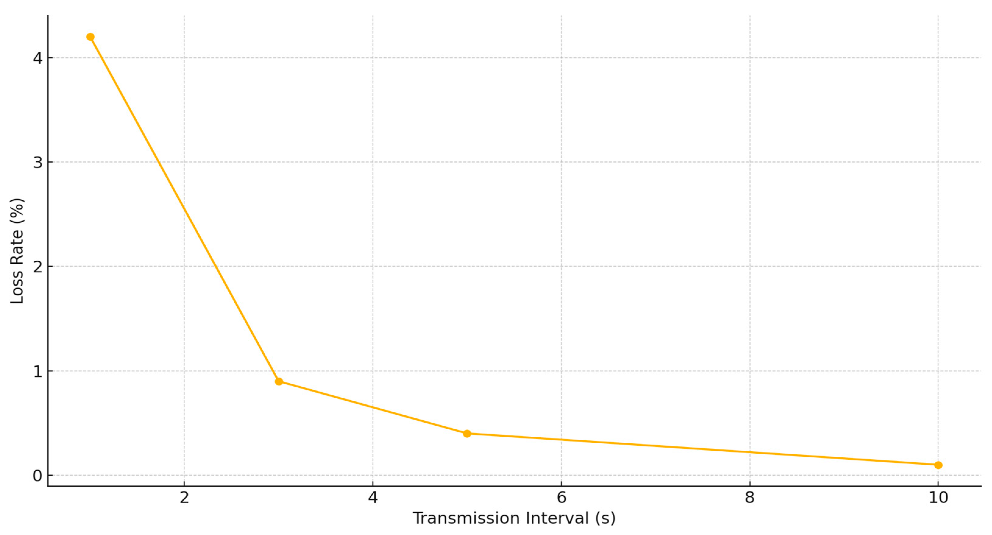
Figure 11.
Average latency vs transmission interval.
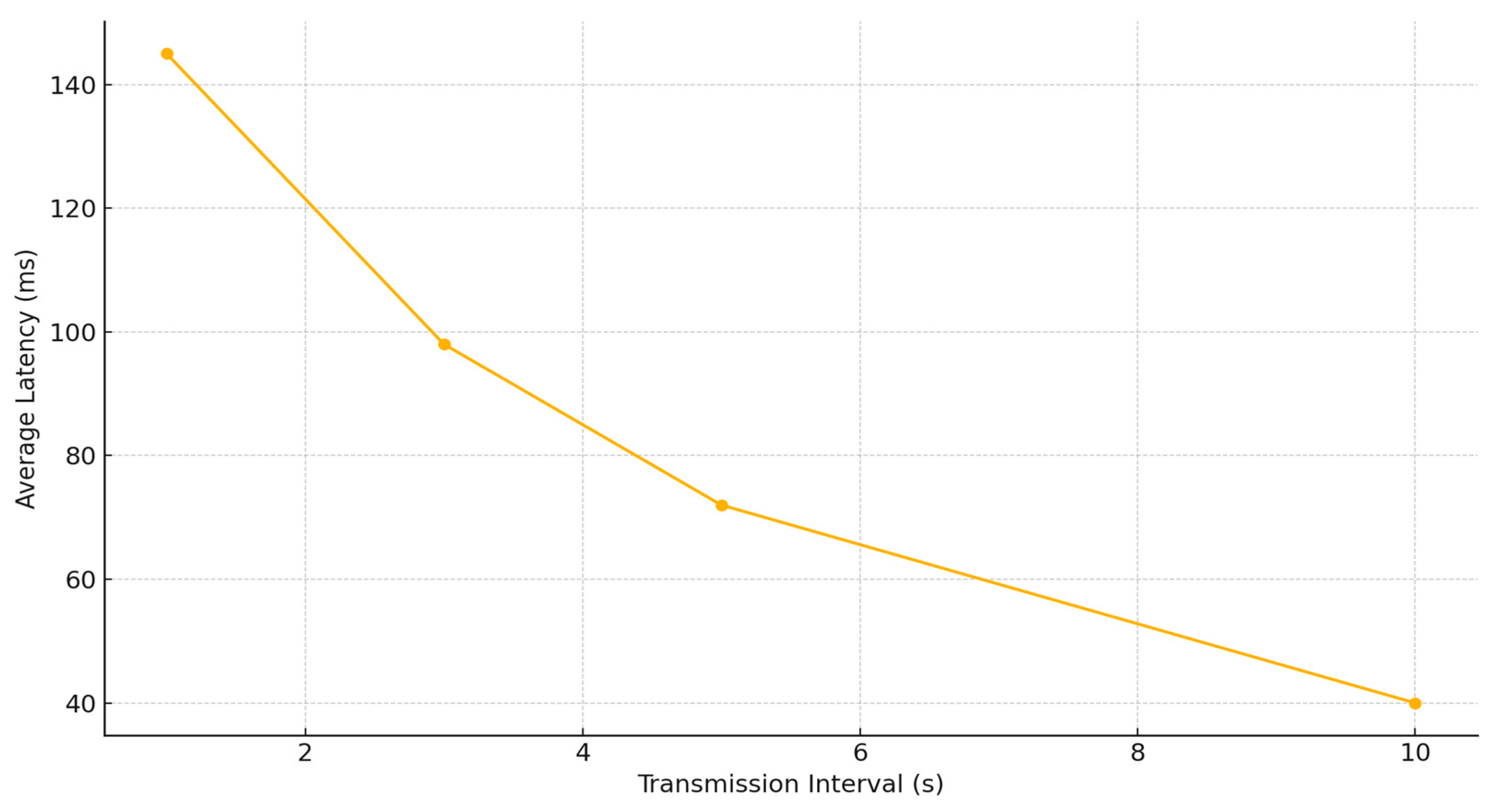
Figure 12.
Message throughput vs transmission interval.
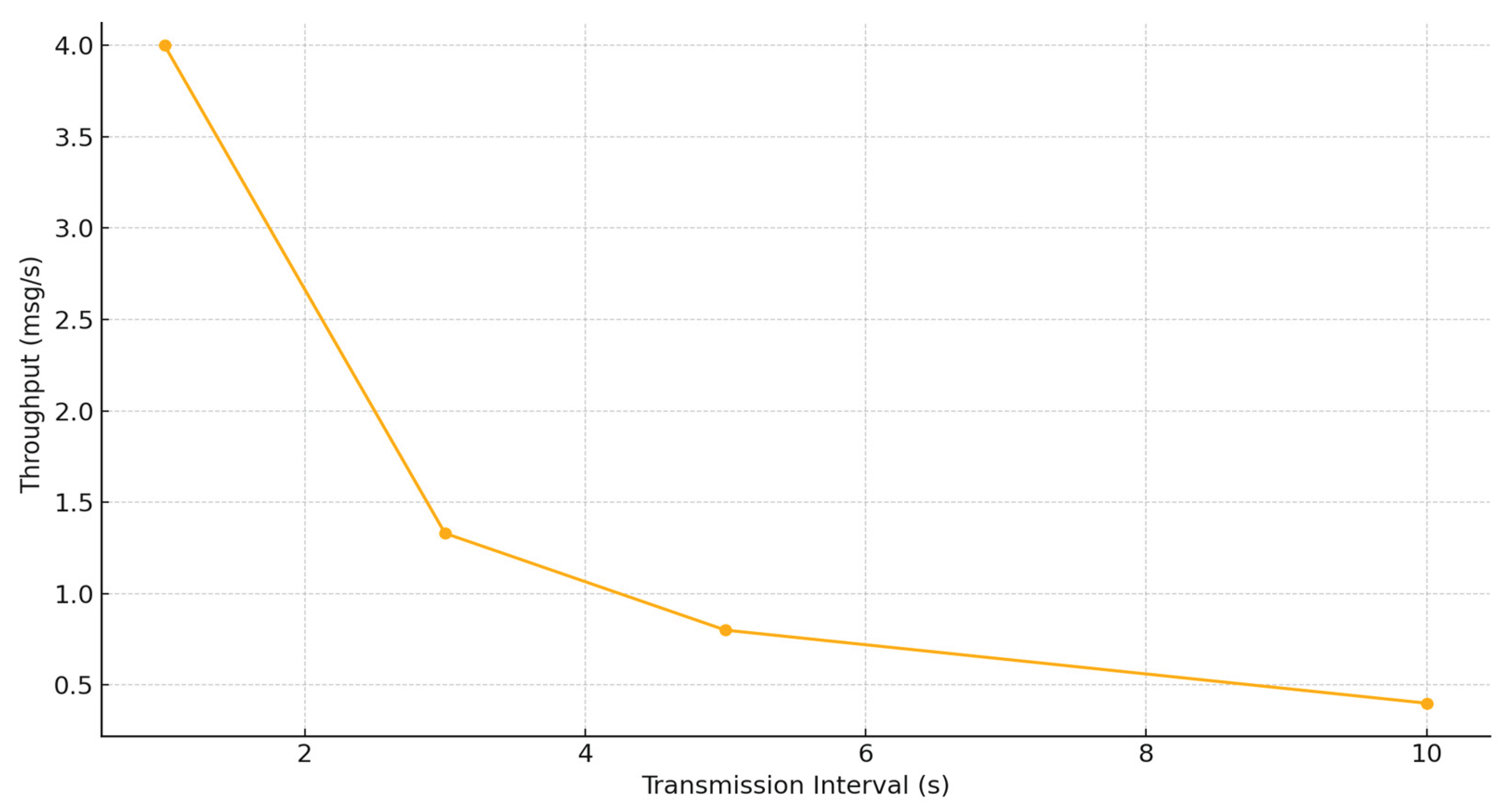
Figure 13.
Average latency comparison.
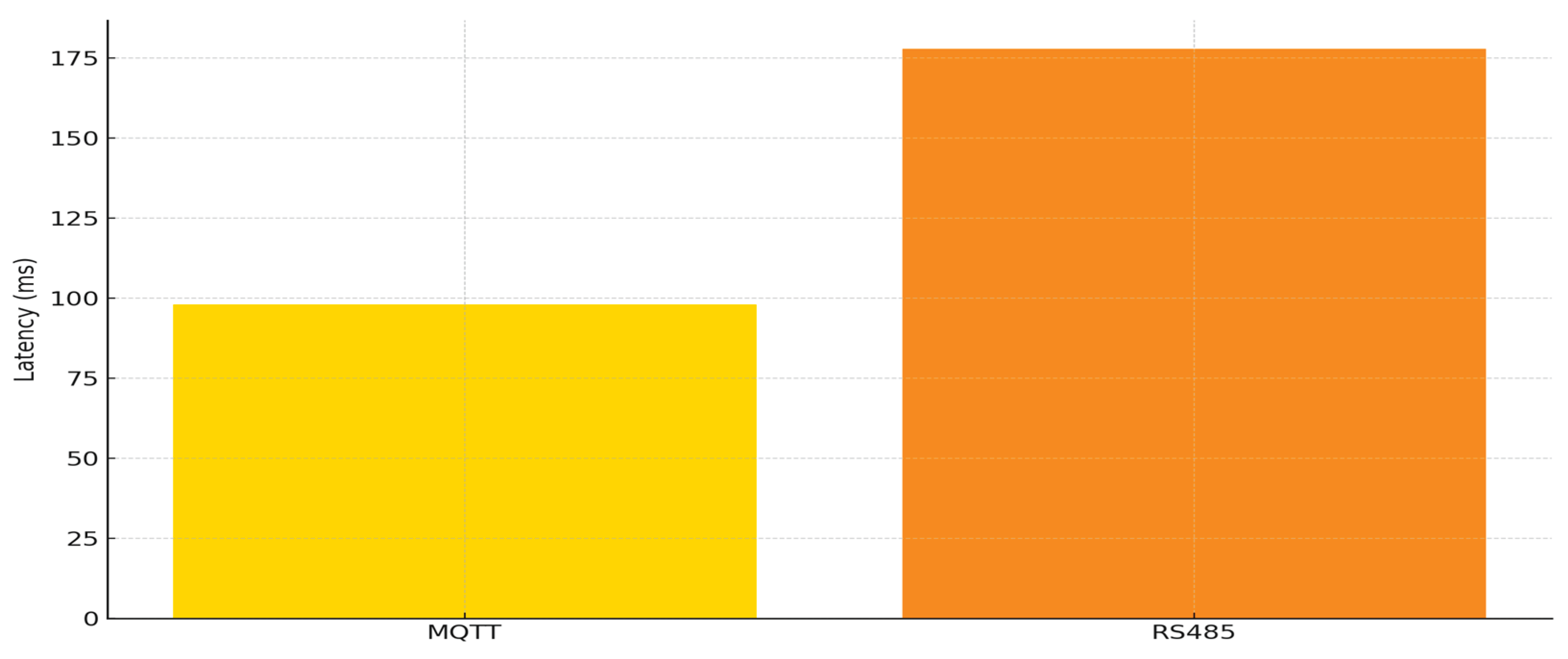
Figure 14.
Message success rate comparison.
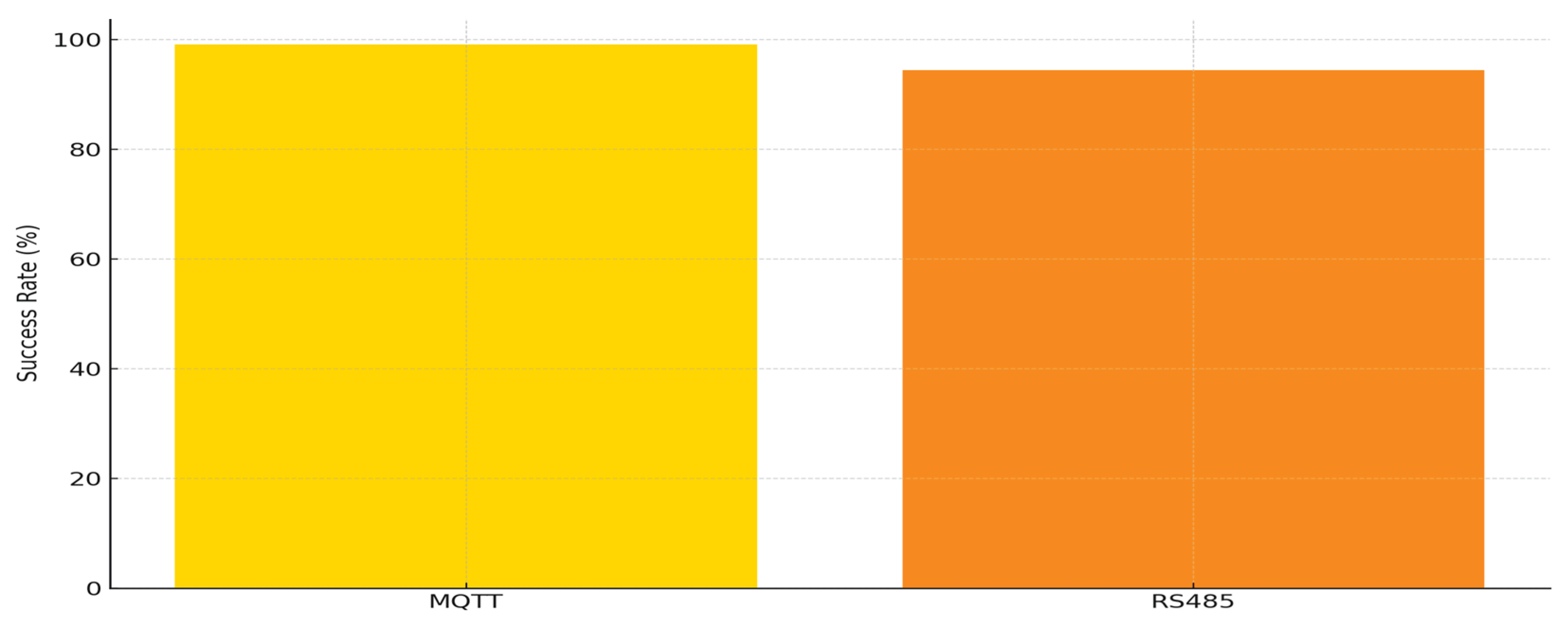
Figure 15.
Message throughput comparison.
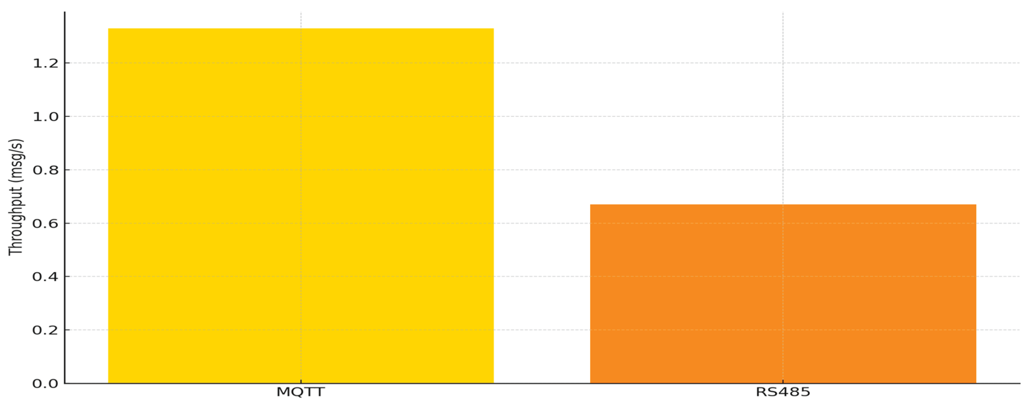
Table 1.
Hardware configuration for the proposed smart livestock monitoring system.
| Component | Model/Specs | Main functions and roles |
| Sensor node MCU | ESP32-WROOM-32 | Wi-Fi-enabled microcontroller, MQTT Publish |
| Temperature/humidity sensor | DHT 22 | Digital temperature/humidity measurement, ±0.5°C accuracy |
| CO2 sensor | MH-Z19B | 0–5000 ppm measurement range, UART communication |
| NH3 sensor | MQ-137 | Detection of NH₃ gas concentration, analog output |
| Broker server | NVIDIA Jetson TX2 | Mosquitto MQTT broker, data receipt/processing |
| Wireless network | 2.4 GHz Wi-Fi router (shared network) | Linking communication between sensor nodes and the broker |
| Storage device | SSD embedded on Jetson TX2 + SQLite | Message storage and logging |
Note: SSD, solid state drive; UART, Universal Asynchronous Receiver/Transmitter).
Table 2.
MQTT configuration parameters used in the proposed system.
| Parameter | Configuration | Description |
| Broker software | Eclipse Mosquitto v2.0 | Open-source MQTT broker |
| Broker platform | Ubuntu 18.04 on Jetson TX2 | Execution environment for the broker |
| Communication port | 1883 | Default MQTT port (non-encrypted) |
| QoS level | 1 | Guarantees message delivery at least once |
| Topic structure | /env/[sensor_type]/[node_id] | Identifies sensor type and node ID |
| Message format | JSON (UTF-8 encoded) | Includes environmental values and timestamp |
| Publishing interval | 2 s | Fixed interval between sensor messages |
| Data storage | SQLite database (local) | Stores received messages and metadata |
| Communication model | Asynchronous, non-blocking | Enables parallel message processing |
Table 3.
MQTT message topics for various environmental parameters in a smart livestock facility.
| Sensor Type | MQTT Topic | Unit | Description |
| Temperature | /env/temp/1 | °C | Ambient air temperature in the livestock barn |
| Humidity | /env/hum/1 | % | Relative humidity |
| Carbon dioxide (CO₂) | /env/co2/1 | ppm | CO₂ concentration |
| Ammonia (NH₃) | /env/nh3/1 | ppm | NH₃ concentration |
| Fine dust (PM2.5) | /env/pm25/1 | µg/m³ | PM2.5 concentration |
| Volatile Organic Compounds | /env/voc/1 | Index/ppm | VOC index or concentration |
| Illuminance | /env/lux/1 | lux | Light intensity inside the barn |
| Noise | /env/noise/1 | dB | Noise level inside the facility |
| Atmospheric pressure | /env/pressure/1 | hPa | Air pressure inside the barn |
| Water temperature | /env/watertemp/1 | °C | Temperature of the drinking water tank |
Table 6.
Comparison of the technical differences between the MQTT and RS485 communication structures.
Table 6.
Comparison of the technical differences between the MQTT and RS485 communication structures.
| Feature | MQTT | RS485 |
| Communication Type | Publish/Subscribe (asynchronous) |
Master/Slave (polling, synchronous) |
| Transmission Path | Broker-based, supports multiple topics | Point-to-point (P2P), sequential polling |
| Scalability | High (easy to add nodes) | Limited (bus collision and cable length constraints) |
| Flexibility | High (supports wireless and modular configuration) | Low (limited by fixed wiring structure) |
| Communication Latency | Low (adjustable via QoS level) | Increases with the number of nodes |
| Transmission Reliability | Configurable QoS levels (0 to 2) | Fixed reliability (requires manual retransmission if failed) |
Table 7.
Experimental setup overview.
| Item | Description |
| Test Site | Smart livestock facility in Suncheon, Jeollanam-do, Korea |
| Network Configuration | Wi-Fi (IEEE 802.11n); all nodes connected under the same AP |
| Broker Location | Mosquitto MQTT broker installed on Jetson TX2 device |
| Number of Nodes | 2 to 8 nodes (adjusted by scenario) |
| Sensor Types | Temperature, humidity, CO₂, NH₃ sensors |
| Transmission Interval | 1 s to 10 s (varied by scenario) |
| Measurement Duration | 10 min per condition, Three repetitions for each setting |
| Comparison System | RS485 polling-based system using RS485-USB converter |
| Measured Parameters | Message success rate (%), average/max latency (ms), message throughput (msg/s), number of communication errors |
Table 8.
Limitations and future improvements.
| Category | Limitation | Future Improvement Plan |
| Single Broker Model | All sensor nodes are connected to a single MQTT broker, which may cause bottlenecks as the number of nodes increases. | Apply a clustered broker architecture with load-balancing mechanisms. |
| Fixed Experiment Parameters | Only the number of nodes and transmission intervals were varied, while other factors such as packet size or QoS were fixed. | Conduct experiments by varying multiple parameters (QoS levels, packet sizes, topic structures, etc.). |
| Farm Network Environment | System was tested under stable indoor Wi-Fi, which may not reflect real-world farm environments. | Evaluate communication robustness under variable farm conditions and consider alternative wireless technologies (e.g., LTE-M, LoRa). |
| Lack of Real-Time Control Integration | System focuses on data collection only and does not include actuator control via controllers. | Design and implement a bi-directional system linking environmental monitoring with actuator control. |
Disclaimer/Publisher’s Note: The statements, opinions and data contained in all publications are solely those of the individual author(s) and contributor(s) and not of MDPI and/or the editor(s). MDPI and/or the editor(s) disclaim responsibility for any injury to people or property resulting from any ideas, methods, instructions or products referred to in the content. |
© 2025 by the authors. Licensee MDPI, Basel, Switzerland. This article is an open access article distributed under the terms and conditions of the Creative Commons Attribution (CC BY) license (https://creativecommons.org/licenses/by/4.0/).
Copyright: This open access article is published under a Creative Commons CC BY 4.0 license, which permit the free download, distribution, and reuse, provided that the author and preprint are cited in any reuse.


