
Submitted:
22 October 2025
Posted:
23 October 2025
You are already at the latest version
Abstract
Sustainable urban energy is based on innovative solar and wind solutions. The paper presents such a hybrid solar-wind system, easy to place on building terraces, highlighting the advantages of this technical solution: energy production as close as possible to the consumers, elimination of system losses, small installation space. The system operates well in the low-speed range for the horizontal-axis crossflow wind turbine placed under a flexible solar panel, at speeds between 3-8 m/s, and exhibits good efficiency by cooling the photovoltaic panels. The prototype proposed by the paper is a small-scale model that can produce, on average 400 Wh/day and about 150 kWh/year. The paper analyzes numerically the aerodynamic behavior of the prototype at several wind speeds, as well as experimental results regarding the power and power coefficient for the wind turbine, as well as the power and efficiency of the flexible solar panel in the hybrid system.
Keywords:
hybrid solar-wind system
; new design
; experimental study
; optimal operation range
1. Introduction
The two energy sources – solar and wind, are complementary in most areas of the globe. The capture and use of these two energy sources continue to occupy the first place among renewable energies.
The continuous development of wind energy generation technologies focuses on increasing productivity, reducing the costs, and developing turbine designs that operate at low wind speeds [1]. A challenge for urban solar and wind energy is their integration into building architecture [2,3]. An investigation on wind flow in suburban environments characterized by buildings with different roof profiles found that flow characteristics in such conditions are highly dependent upon the roof type on which the turbine is mounted [4]. The flat roof is found to be the best solution on paper [5]. According to other authors, the ridge roof is better, multiplying the wind speed by 1.5 – 2.2 times [6].
A frequently used solution is the crossflow rotor for capturing wind energy, which can be mounted horizontally, for a more compact, vibration-free structure, which enters the wind at air speeds below 2 m/s [6,7,8].
Previous studies have analyzed the performance of these sources separately or together, developed applications with crossflow wind turbines, highlighting the advantages of positioning wind turbines on the roofs or terraces of buildings. Producing sustainable energy in urban areas, with low costs and eliminating energy transport losses, but also with small installation areas, hybrid solutions have been proposed, like:
i) WindRail was designed in Zurich, Switzerland by the Anerdgy, (Windkraft-Journal, 24. January 2014) [9].
ii) Bluenergy solar wind turbine, 2020, a system with a vertical Savonius wind turbine with integrated photovoltaic cells, bluenergyusa.com [10].
iii) Solar-Powered Wind Turbine, designed in 2013 at the University of Liverpool (Joe King, 2013), has a horizontal wind turbine, with photovoltaic cells integrated on the blades of the wind turbines [11].
These have a series of technological limitations related to geometry, shading etc.
WindRail [9] is a new hybrid system that has been designed by Anerdgy for residential terraces. It uses the pressure difference that is created by the wind blowing through the buildings. This system consists of a horizontal axis wind turbine and solar panels.
The Bluenergy Solarwind Turbine features double-helix curved wind blades mounted on a vertical axis, covered with solar cells. Instead of using glass, the cells are covered with clear Teflon. When the wind is blowing, the solar cells are cooled by the rotation, which is set to assist in maximum electricity generation. The model is 18’ tall and 6’ wide, including turbine, generator and inverter, produces 5 kW. One can produce 3kW from wind, with a mean speed of 5.6 m/s, assuming 9 hours of operation. In 30 days/month, results 810 kWh/month. From the Sun one can produce 2 kW, assuming 6.5 hours per day, in 24 days/month, resulting in 312 kWh/month [10].
Also, the University of Liverpool has upgraded a wind turbine with a new set of spinning solar blades, thereby incorporating photovoltaic technology into traditional turbines [11]. Researchers were designed a horizontal wind turbine, with photovoltaic cells integrated on the blades of the wind turbines.
The device is produced in two-meter modules and can generate from 1,500 to 2,000 kWh/ year [11].
This paper introduces a new design system that integrates the two energy sources, solar and wind, on the model two-in-one, having advantages like: a small space by placing it on the terraces of buildings, additional energy by cooling the photovoltaic panel, higher total energy from two sources, and better hybrid system efficiency.
In addition, even in the absence of wind, the system works if the crossflow wind turbine is positioned at the polluted air exhaust vents of office or commercial buildings.
The objectives of this study are: to design and manufacture a hybrid solar-wind model, with a 700 mm long and 200 mm diameter of crossflow wind turbine and a 25 W monocrystalline Si-based solar PV panel and to test the model. Operating performance will be highlighted in this paper: energy increase using the two sources, identification of the optimal operating range concerning the turbine parameters, and about the additional energy obtained by cooling the solar panel by rotating the turbine placed under the photovoltaic panel.
2. Design and Manufacturing of the Hybrid Solar-Wind System
The model consists of a support for the photovoltaic panel, profiled to represent a case for the crossflow wind turbine, made largely from 3D-printed components.
Based on previous studies [12,13,14,15,16,17,18], the cross flow turbine with outer diameter D=0.2 m, inner diameter d=0.14 m, length L=700 mm (consisting of 5 sections of 140 mm) was designed. The blades in a number of 18 have NACA 4412 profile, chosen from [19], they are not constructed with a single radius of curvature for better power coefficient. The blades have an inlet angle 1=30° and an outlet angle 2=90°. The air passes 2 times through the rotor and provides a better turning moment. The prototype was manufactured by 3D printing from PLA (biodegradable plastic - polylactic acid).
The flexible photovoltaic panel (FWAVE Solar Modules 25W, thin-film amorphous-silicon [20]) is placed on the specially designed support above the wind rotor with horizontal axis. The maximum power of 25 W is obtained at solar irradiance of 1000 W/m2.
3. Numerical Analysis of the Flow Through the Wind Rotor
To identify the optimal rotor shape and suction guide airfoil, the study used numerical analysis methods. The NACA 4412 airfoil blade shape was drawn with the OnShape application, and the numerical analysis were performed with SimScale.
The initial conditions were atmospheric pressure and zero velocity on solid parts and the boundary conditions for the inlet wind speed were setted to 3, 6 and 8.5 m/s. The results in Figure 3 show the aerodynamic behavior of the rotor and the fact that at low speeds vortices, turbulence, unsteady running are visible. At speeds above 6 m/s this turbulence is reduced, and at 8.5 m/s the performance seems to be even better, by attenuation of the peripheral vortices.
4. Experimental Setup and Results
4.1. Experimental Setup
The experimental study focuses on identifying the optimal operating range for both the wind turbine and the solar panel to maximize the energy produced.
For testing the crossflow turbine, the air flow was created by a centrifugal fan. The air speed varied with the fan discharge flap. Wind velocity measurements were carried out with a hot-wire anemometer, with an accuracy of ±0.1 m/s, and a digital tachometer for rotation speed with an accuracy of ±0.05%.
For experiments on the power and efficiency of the flexible solar panel in the installation, the solar irradiation was measured with a pyranometer with an accuracy of 2%, and for electrical measurements, on used electronic ammeter and voltmeter with accuracy of ±1%.
4.2. Crossflow Turbine Experimental Results
The computational relations used in this paragraph are the following:
where is the tip speed ratio (TSR) of the turbine, the angular frequency (rad/s), (rpm) the speed, the rotor diameter (m), L the rotor length (m), A area (m2); A=D⋅L
is the wind velocity (m/s) and u is the tangential velocity (m/s).
is the drag force due to air friction with the turbine blades and is the drag coefficient. is the lift force and is the lift coefficient. For NACA 4412 profile from airfoil library [19] considering means values for cl=0.6 and cd=0.06. The resultant force is:
The mechanical power is calculated with relation (4)
The theoretical power extracted from the wind is given by
The power coefficient ( can be computed with equation (6):
In Table 1 there are the experimental results for the crossflow turbine.
With the results from Table 1, Figure 4 are plotted the theoretical power obtained from wind and mechanical power.
Good behavior is observed, with power coefficient between (0.2÷0.31) at wind speeds of 3-8 m/s. At velocity of 0.4 m/s the rotor enters slightly into the wind. At wind speeds above 9 m/s, the power coefficient decreases and vibrations appear.; the rotor behaves well at low wind speeds. An operating optimum from the experiment would be at 3-8 m/s, which is also demonstrated numerically. For this range, the power coefficient is good, and the tip speed ratio λ is about 0.53.
4.3. Photovoltaic Panel Experiments
For experiments on the power and efficiency of the flexible solar panel in the installation, the solar irradiation was measured using a pyranometer with an accuracy of 2%, and for electrical measurements, electronic ammeter and voltmeter with accuracy of ±1% were used.
The experiments were performed at a mean global irradiation G=600 W/m2, in May 2025. The energy characteristics current ands voltage I(U), and power and voltage P(U), with and without panel cooling (when the wind turbine was running or not) were plotted.
The solar panel efficiency can be determined with the relation:
The area of photovoltaic panel A is 0.171 m2, P is the electrical power obtained with the solar panel and G is the global irradiation, W/m2.
5. Hybrid System Performances Analysis
With the experimental model designed and manufactured largely with 3D printed components, a power of 15 W from solar energy (for solar radiation of 600 W/m2) and 25W (for solar radiation of 1000 W/m2), and from wind energy, a power of 20 W is produced (with a crossflow turbine with an efficiency of 0.3). If the solar panel operates on average 6 hours per day and the wind turbines 12 hours per day, an average of 405 Wh/day or approximately 150 kWh/year can be obtained.
For a household with an average monthly consumption of 150 kWh/month or 5000 Wh/day, it can determine the number of solar-wind hybrid systems needed as follows:
With 12 or 13 systems, energy can be provided for a home under the assumptions. The energy over a year is about at 150 kWh/year, with this innovative small hybrid model.
6. Conclusions
The new model of hybrid solar-wind system has good behavior and many advantages:
- Complementary energy sources on the model - two sources in one system, with a small placement space.
- Numerical simulations confirmed the geometry and predicted the optimal aerodynamic behavior of the system.
- Low wind velocity for the in-wind entry of the turbine: 0.4 m/s.
- The best power coefficient was over for wind velocity between 5-8 m/s.
- The photovoltaic panel provides 8-10% more power by air cooling with the crossflow turbine.
- The total power exceeds 45 W with this small experimental model, so the average energy is 405 Wh/day.
The good performance obtained with this hybrid system motivates us to continue research on larger prototypes.
Further developments will analyze the optimal distance between the wind turbine and the solar photovoltaic panel, as well as larger-scale prototypes with a rotor diameter of 0.5 m and a length of 2 m, which also requires a solar panel of at least 250 W placed on top of the turbine.
Author Contributions
Conceptualization, S.B. and G-L.M.; methodology, S.B. and G-F.F.; model manufacture, G-F.F..; writing—original draft preparation, A.M.; writing—review and editing, S.B.
Conflicts of Interest
The authors declare no conflicts of interest.
References
- IEA.org, https://www.iea.org/energy-system/renewables/wind#tracking (accessed on May 10, 2025).
- Innoenergy, https://www.innoenergy.com/discover-innovative-solutions/customer-cases/french-hypermarket-gets-24-7-energy-autonomy-sun-wind-combined/ (accessed on October 5, 2025).
- BKV Energy, https://bkvenergy.com/blog/wind-turbines-for-homes/ (accessed on October 5, 2025).
- Wilberforce, T.; Olabi, A. G.; Sayed, E. T.; Alalmi, A. H.; Abdelkareem, M. A. . Wind turbine concepts for domestic wind power generation at low wind quality sites. Journal of Cleaner Production 2023, 394, 136137. [Google Scholar] [CrossRef]
- Ledo, L.; Kosasih, P.B.; Cooper, P. Roof mounting site analysis for micro-wind turbines. Renewable Energy 2011, 36, 1379–1391. [Google Scholar] [CrossRef]
- The power collective, Ridge Blade RB https://www.switchontario.ca/resources/Documents/Managing%20Energy%202017/Managing%20Energy%202017%20-%20Business%20-%20RidgeBlade%20-%20Llion%20Rowlands.pdf (accessed on September 15, 2025).
- Sefidgar, Z.; Ahmadi Joneidi, A.; Arabkoohsar, A. A Comprehensive Review on Development and Applications of Cross-Flow Wind Turbines. Sustainability 2023, 15, 4679. [Google Scholar] [CrossRef]
- Budea, S. Assessment regarding the performances of wind turbines from the roofs of buildings. E3S Web Conferences 2023, 404, 02005. [Google Scholar] [CrossRef]
- .
- Windkraft-Journal, 24 January 2014, Building design and construction. https://www.bdcnetwork.com/urban-wind-and-solar-energy-system-may-actually-work, (accessed on May 5 2025).
- Bluenergy solar wind turbine https://www.mwps.co.uk/wind-energy-news/wind-power-news/2020/solar-wind-turbine-the-revolutionary-bluenergy-solarwind-turbine/ (accessed on May 10 2025).
- Inhabitat, Scientists Develop Solar-Powered Wind Turbine for Ultimate Energy Generation, 04/01/2013 https://inhabitat.com/scientists-develop-solar-powered-wind-turbine/, (accessed on May 10 2025).
- Mockmore, C.A.; Merryfield, F. The Banki water turbine, Bulletin series no. 25, 1949, Engineering experiment station, Oregon State College, https://www.pumpfundamentals.com/banki_scan.pdf.
- Burton, T.; Sharpe, D.; Jenkins, N.; Bossanyi, E. Wind Energy Handbook, 2nd ed., Chichester: Wiley, p 220-309, 2011.
- Trevor, M. L. Wind Energy Engineering - A Handbook for Onshore and Offshore Wind Turbines, cap. 9 Martin Hansen, O.L. Aerodynamics and Design of Horizontal-Axis Wind Turbines, Elsevier Academic Press, 161-183, 2017.
- Acharya, N. ; Chang-Gu Kim; Bhola Thapa;Young-Ho Lee. Numerical analysis and performance enhancement of a crossflow hydro turbine, Renewable Energy 2015, 80, 819–826. [Google Scholar]
- Wibowo, A.; Tjahjana, D.D.D.P.; Santoso, B.; Situmorang, M.R.C. Study of turbine and guide vanes integration to enhance the performance of cross flow vertical axis wind turbine. AIP Conf. Proc. 2018, 1931, 030043. [Google Scholar] [CrossRef]
- Pujol, T.; Massaguer, A.; Massaguer, E.; Montoro, L.; Comamala, M. Net Power Coefficient of Vertical and Horizontal Wind Turbines with Crossflow Runners. Energies 2018, 11, 110. [Google Scholar] [CrossRef]
- Adhikari, R.; Wood, D. The Design of High Efficiency Crossflow Hydro Turbines: A Review and Extension. Energies 2018, 11, 267. [Google Scholar] [CrossRef]
- Airfoil Tools http://airfoiltools.com/airfoil/details?airfoil=naca4412-il (accessed on May 5 2025).
- Fuji Electric, 92W FWAVE Solar Modules https://www.scribd.com/document/468906307/Calculationsolar-module-FUJI-FPV1092COM2843 (accessed on May 5 2025).
- Budea, S.; Simionescu, Ș. M. Solar hybrid system for electricity and air heating – Experimental research. IOP Conference Series: Earth and Environmental Science 2023, 1185, 012001. [Google Scholar] [CrossRef]
Figure 1.
Hybrid solar-wind system .
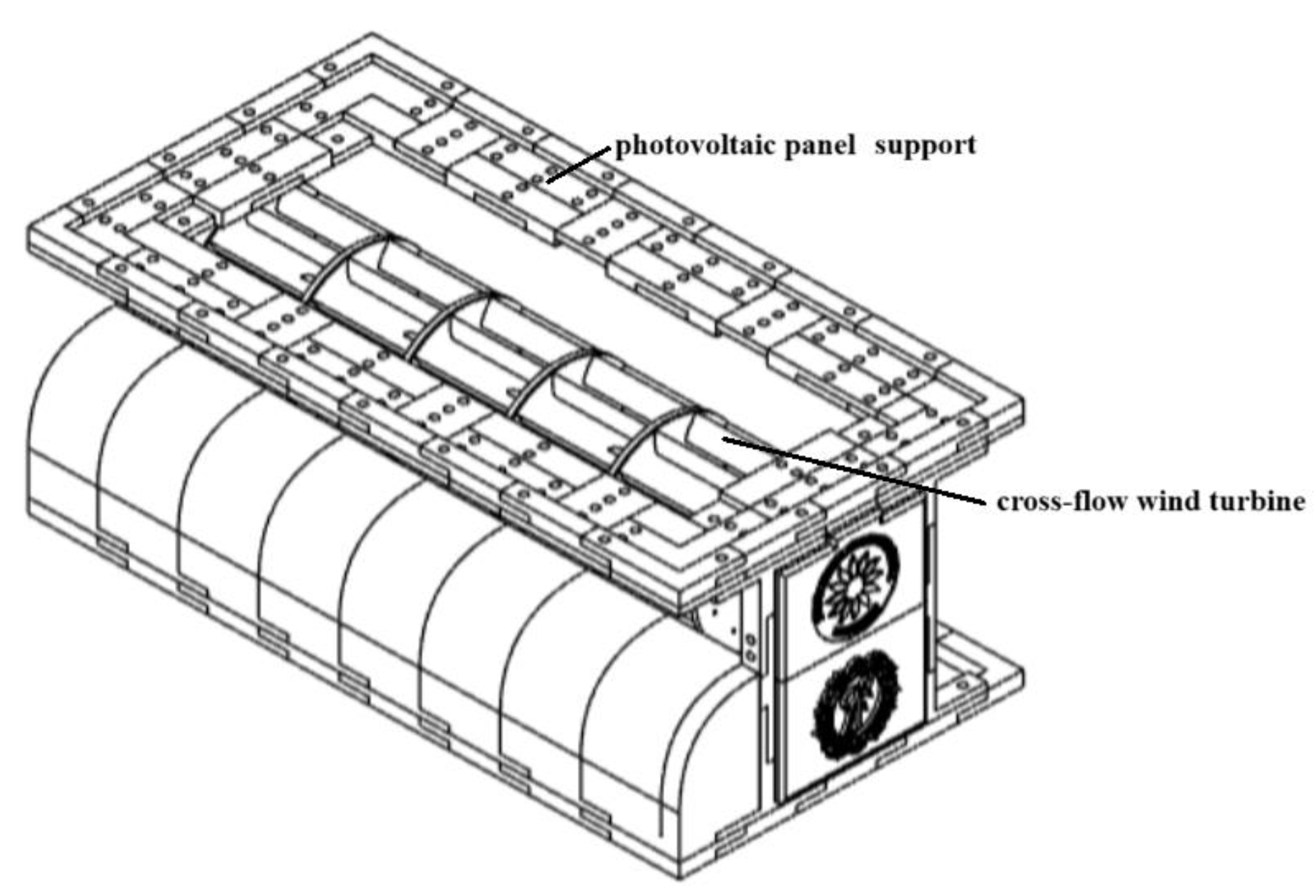
Figure 2.
Hybrid system model manufactured by 3D printing, with front (inlet) side (a) and back (outlet) side (b).
Figure 2.
Hybrid system model manufactured by 3D printing, with front (inlet) side (a) and back (outlet) side (b).
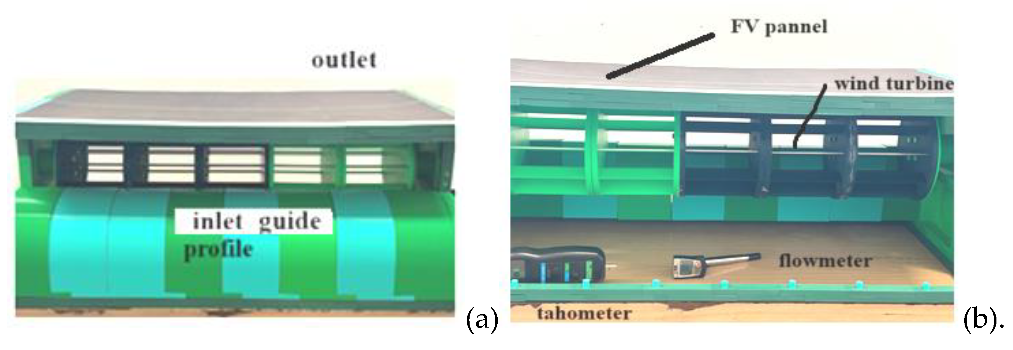
Figure 3.
Velocities distribution in cross flow turbines, for inlet speeds of 3 m/s (a), 6 m/s (b) and 8.5 m/s (c).
Figure 3.
Velocities distribution in cross flow turbines, for inlet speeds of 3 m/s (a), 6 m/s (b) and 8.5 m/s (c).
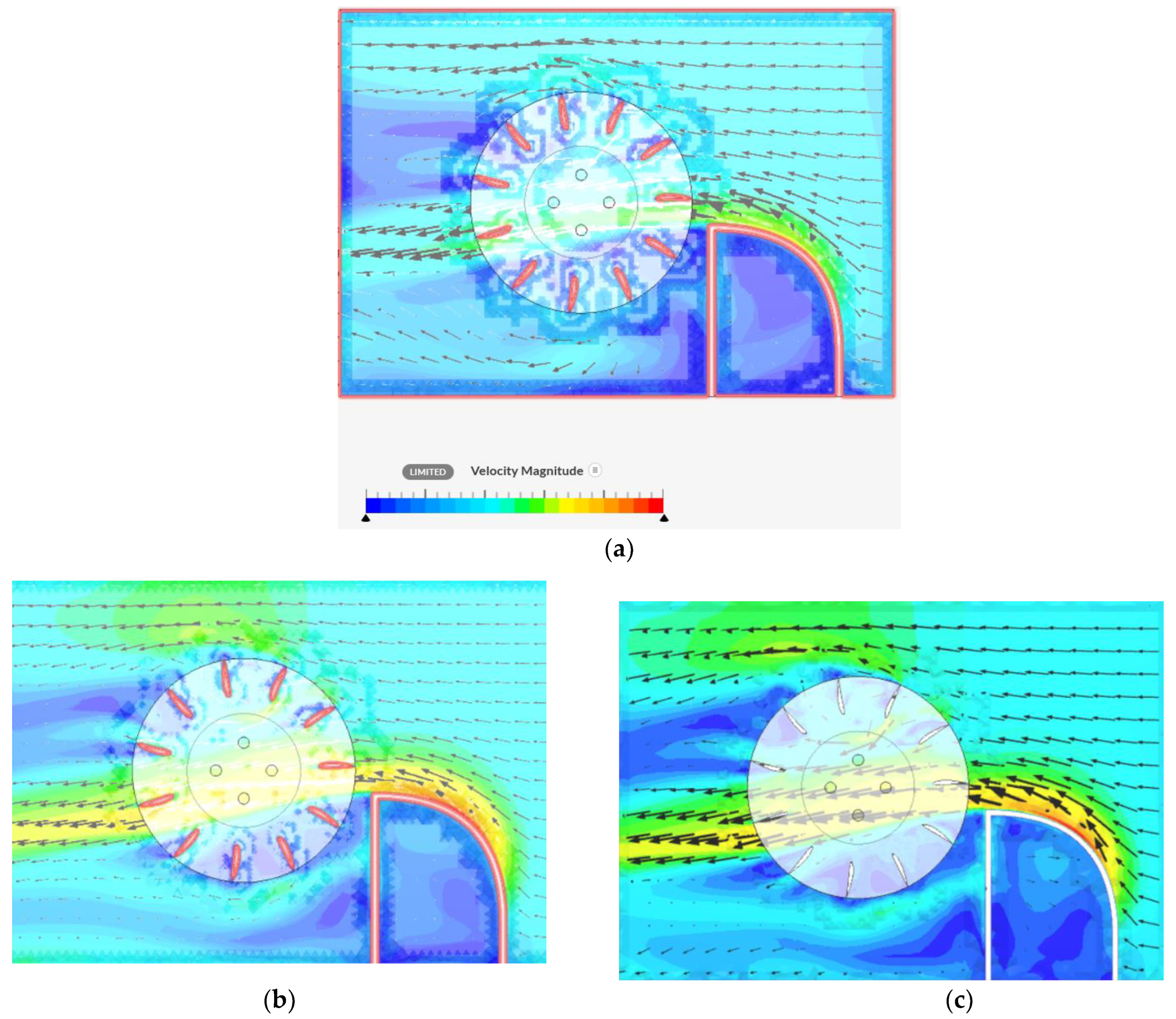
Figure 4.
Turbine theoretical power and mechanical power vs wind velocity.
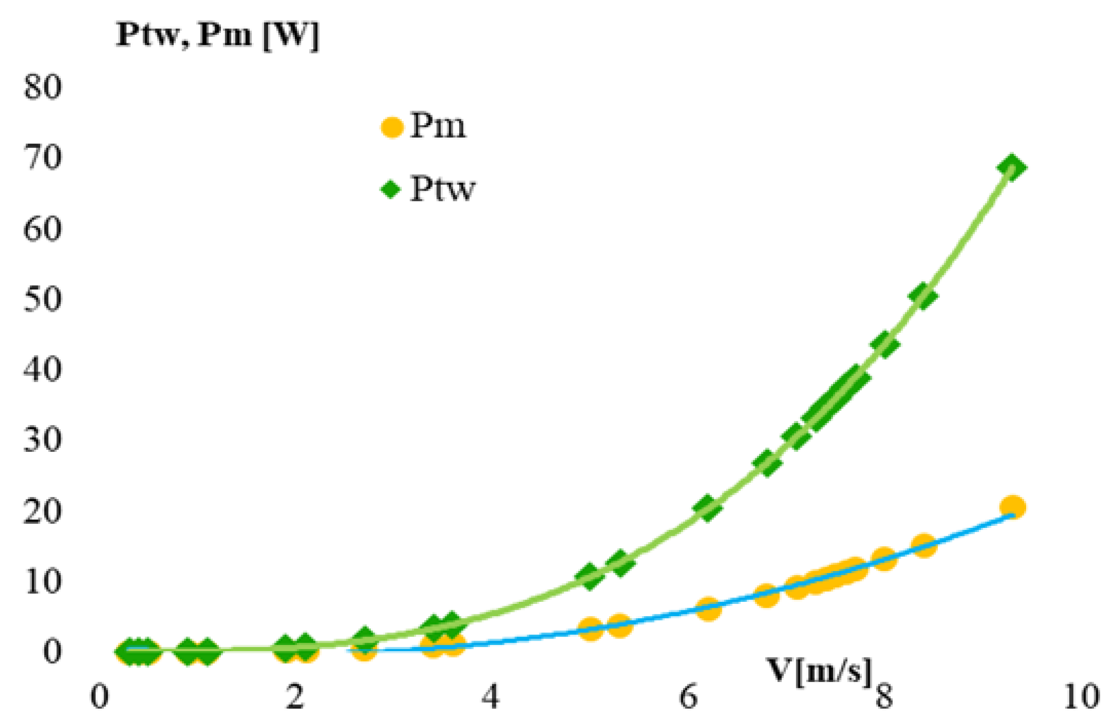
Figure 5.
Experimental characteristics of the solar panel with and without cooling for a mean solar irradiation of 600 W/m2.
Figure 5.
Experimental characteristics of the solar panel with and without cooling for a mean solar irradiation of 600 W/m2.
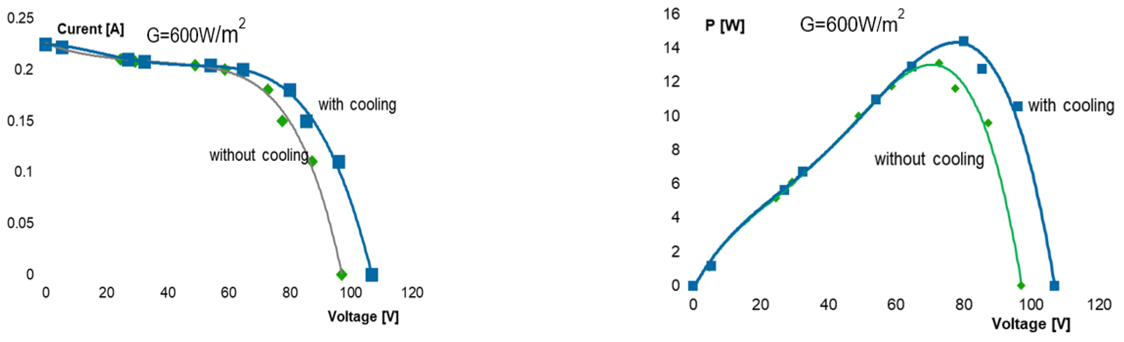

Table 1.
Experimental Results for the Wind Turbine.
| No | V [m/s] | n [rpm] | u [m/s] | Fl [N] | Fd [N] | Fr [N] | Pm [W] | Ptw [W] | cp (-) | λ[-] |
| 1 | 0.3 | 12 | 0.1256 | 0.0046 | 0.00023 | 0.00461 | 0.0007 | 0.00230 | 0.2516 | 0.4188 |
| 2 | 0.4 | 18 | 0.1884 | 0.0081 | 0.00041 | 0.00820 | 0.0016 | 0.00546 | 0.2830 | 0.4712 |
| 3 | 0.5 | 20 | 0.2094 | 0.0128 | 0.00064 | 0.01282 | 0.0032 | 0.01067 | 0.2516 | 0.4188 |
| 4 | 0.9 | 35 | 0.3665 | 0.0415 | 0.00207 | 0.0415 | 0.0187 | 0.06225 | 0.2446 | 0.4072 |
| 5 | 1.1 | 43 | 0.4502 | 0.062 | 0.0031 | 0.0620 | 0.0341 | 0.11366 | 0.2459 | 0.4093 |
| 6 | 1.9 | 94 | 0.9843 | 0.1849 | 0.00924 | 0.1852 | 0.1757 | 0.58575 | 0.3112 | 0.5180 |
| 7 | 2.1 | 106 | 1.1100 | 0.2259 | 0.01129 | 0.2262 | 0.2373 | 0.79088 | 0.3175 | 0.5285 |
| 8 | 2.7 | 132 | 1.3823 | 0.3735 | 0.01867 | 0.3740 | 0.5043 | 1.68092 | 0.3075 | 0.5119 |
| 9 | 3.4 | 172 | 1.8011 | 0.5923 | 0.02961 | 0.5930 | 1.0070 | 3.35656 | 0.3182 | 0.5297 |
| 10 | 3.6 | 184 | 1.9268 | 0.6640 | 0.03320 | 0.6649 | 1.1953 | 3.98442 | 0.3215 | 0.5352 |
| 11 | 5 | 233 | 2.4399 | 1.281 | 0.06405 | 1.2826 | 3.2025 | 10.675 | 0.2931 | 0.4879 |
| 12 | 5.3 | 235 | 2.4609 | 1.4393 | 0.07196 | 1.4411 | 3.8142 | 12.7141 | 0.2789 | 0.4643 |
| 13 | 6.2 | 241 | 2.5237 | 1.9696 | 0.09848 | 1.9721 | 6.1060 | 20.3532 | 0.2445 | 0.4070 |
| 14 | 6.8 | 270 | 2.8274 | 2.3693 | 0.11846 | 2.3722 | 8.0557 | 26.8524 | 0.2497 | 0.4157 |
| 15 | 7.1 | 298 | 3.1206 | 2.5830 | 0.12915 | 2.5862 | 9.1697 | 30.5656 | 0.2640 | 0.4395 |
| 16 | 7.3 | 292 | 3.0578 | 2.7305 | 0.13652 | 2.7339 | 9.9666 | 33.2220 | 0.2516 | 0.4188 |
| 17 | 7.4 | 290 | 3.0368 | 2.8059 | 0.14029 | 2.8094 | 10.3818 | 34.6063 | 0.2465 | 0.4103 |
| 18 | 7.5 | 289 | 3.0264 | 2.8822 | 0.14411 | 2.8858 | 10.8084 | 36.0281 | 0.2424 | 0.4035 |
| 19 | 7.6 | 287 | 3.0054 | 2.9596 | 0.14798 | 2.9633 | 11.2466 | 37.48855 | 0.2375 | 0.3954 |
| 20 | 7.7 | 288 | 3.0159 | 3.0380 | 0.15190 | 3.0418 | 11.6964 | 38.98792 | 0.2353 | 0.3916 |
| 21 | 8 | 283 | 2.9635 | 3.2793 | 0.16396 | 3.2834 | 13.1174 | 43.7248 | 0.2225 | 0.3704 |
| 22 | 8.4 | 282 | 2.9530 | 3.6154 | 0.18077 | 3.6200 | 15.1851 | 50.61692 | 0.2111 | 0.3515 |
| 23 | 9.3 | 266 | 2.7855 | 4.4317 | 0.22158 | 4.4372 | 20.6076 | 68.69209 | 0.1799 | 0.2995 |
Disclaimer/Publisher’s Note: The statements, opinions and data contained in all publications are solely those of the individual author(s) and contributor(s) and not of MDPI and/or the editor(s). MDPI and/or the editor(s) disclaim responsibility for any injury to people or property resulting from any ideas, methods, instructions or products referred to in the content. |
© 2025 by the authors. Licensee MDPI, Basel, Switzerland. This article is an open access article distributed under the terms and conditions of the Creative Commons Attribution (CC BY) license (http://creativecommons.org/licenses/by/4.0/).
Copyright: This open access article is published under a Creative Commons CC BY 4.0 license, which permit the free download, distribution, and reuse, provided that the author and preprint are cited in any reuse.


