
Submitted:
21 October 2025
Posted:
23 October 2025
You are already at the latest version
Abstract
Hyperspectral images (HSIs) and Light Detection and Ranging (LiDAR) provide complementary spectral and structural information for remote sensing tasks such as land cover classification. To utilize these modalities, we propose a hybrid Graph Wavelet Convolution Transformer (MS-GWCT) model that combines multi-scale graph wavelet convolutions with Transformer-based attention mechanisms. The model constructs a graph over labeled pixels, using normalized adjacency matrices with optional Gaussian weighting based on spectral and spatial similarities. Graph wavelet convolutions, approximated via Chebyshev polynomials, enable multi-scale feature extraction, while Transformer blocks on the graph capture long-range dependencies and cross-modal interactions. The training process includes focal loss, label smoothing, a supervised contrastive loss, Mixup data augmentation, and stochastic graph augmentation to enhance robustness. Key hyperparameters are automatically optimized using the Schrödinger Optimization Algorithm (SOA). Experiments on the Houston 2013 and Trento datasets show state-of-the-art performance with limited training samples, achieving overall accuracies of 92.60% and 98.86%, respectively, using only 50 labeled pixels per class. Ablation studies confirm the contributions of multi-scale graph convolutions, attention modules, and training strategies, while robustness analyses highlight the model’s effectiveness in conditions of label scarcity and class imbalance.
Keywords:
hyperspectral images
; graph wavelets
; Chebyshev approximation
; multi-scale graph neural networks
1. Introduction
Hyperspectral images (HSIs) and Light Detection and Ranging (LiDAR) complement one another in a mutually reinforcing manner and have become indispensable for remote sensing applications, particularly in land-cover classification [1]. HSIs can provide detailed spectral signatures for the precise discrimination of materials by capturing reflectance across hundreds of contiguous narrow spectral bands. LiDAR can offer accurate three-dimensional structural information and generate elevation and surface profiles that are largely unaffected by illumination and atmospheric conditions [2]. The integration of HSI and LiDAR data enables the simultaneous use of rich spectral, spatial, and height cues, significantly improving the ability to differentiate classes with similar spectral features but varying in vertical structure, such as distinguishing vegetation from structures in urban environments. Early studies show that multimodal fusion outperforms single-source methods. However, the Hughes phenomenon (“curse of dimensionality”) can lead to overfitting and poor generalization. Thus, data fusion should include careful feature selection and dimensionality reduction [3].
Early HSI-LiDAR fusion methods, while effective, were limited by manual feature design and restricted modeling power. However, they demonstrated the potential for improvement in the field. Researchers created spectral indices, principal components, texture measures, and elevation attributes, then combined these features before feeding them into traditional classifiers like Support Vector Machines (SVMs) or Random Forests [4]. This method of feature-level fusion showed that combining spectral and height information improved accuracy compared to using either modality alone. These approaches have often failed to capture the relationships between spectral data and structural details. When many features are used with limited training data, overfitting occurs. With the advances, we can mitigate these problems and enable more accurate and robust HSI-LiDAR fusion.
Deep learning has reshaped feature extraction and fusion by replacing hand-crafted pipelines with data-driven representations. In HSI classification, convolutional neural networks (CNNs) learn joint spectral-spatial features end to end [5]. Multi-branch designs with attention modules emphasize informative bands and neighborhoods, achieving state-of-the-art performance in HSI classification and HSI-LiDAR fusion [6]. LiDAR height maps can be concatenated as auxiliary channels or handled in dedicated branches to inject shape and elevation cues; attention further improves accuracy in urban land-cover mapping. CNNs are easy to train with pretrained backbones and augmentation, but their fixed receptive fields hinder the capture of long-range dependencies and complex structure. These increase the compute and overfitting risk because broadening the context usually means larger patches or deeper models. Furthermore, misalignments between HSI and LiDAR data can adversely affect CNN accuracy, as these models assume precise coregistration.
GNNs naturally handle the irregular, non-Euclidean structure of remote-sensing data. In a typical GCN, pixels or objects (often after superpixel segmentation) become nodes linked to adjacent or similar nodes, letting information move across neighborhoods and multiple hops [7]. Newer multi-scale designs, graph attention networks and graph U-Nets, pool nodes hierarchically to capture long-range context while keeping local detail [8]. Building a combined HSI-LiDAR graph can better preserve shapes and boundaries than patch-based CNNs [9]. With support from spectral graph theory, polynomial spectral filters provide efficient multi-scale convolutions that highlight important frequencies and reduce over-smoothing. Still, deep GNNs bring issues: many layers may over-smooth, large neighborhoods are costly, and naive graphs can connect dissimilar regions and add noise. Results are also sensitive to hyperparameters (connectivity, hops, learning rates). Current practice favors sparse, localized graphs, learnable adjacency, and techniques such as graph dropout and edge pruning to trade off information, noise, and efficiency.
Transformers have been adapted for HSI-LiDAR data fusion to capture complex dependencies and interactions [10]. The Vision Transformer models treat HSI-LiDAR fusion images as sequences of patches, using self-attention to weight information from distant scene regions, aiding in disambiguating similar spectra with broader context. Dual-branch transformer architectures with cross-attention enable direct exchange between HSI and LiDAR features, improving spectral and elevation alignment and classification robustness, and adaptive gating balances modality contributions [11]. Transformers placed after CNN/GCN extractors blend local spectral-spatial features with global context, and fully attention-based spectral-spatial-elevation models fuse imagery and LiDAR within one self-attention stack. Although these models attain high accuracy, their large parameter counts and weaker inductive biases make them data-hungry and computationally intensive, and thus susceptible to overfitting on the small datasets typical of HSI-LiDAR studies. Achieving stable performance requires careful initialization, strong regularization, and meticulous hyperparameter tuning. In limited data scenarios, pure transformers may struggle unless combined with training techniques or hybridized with convolutional layers.
We present a hybrid architecture that couples spectral graph convolutions with transformer-style attention, combining their strengths while mitigating their weaknesses. Spectral graph convolution—implemented with localized, multi-scale filters- is well-suited to HSI-LiDAR data, capturing fine detail and smooth regions with relatively few parameters. Transformer attention on the graph dynamically adjusts the influence of neighboring nodes, thereby expanding the receptive field without requiring very deep networks. Built for robustness, our MS-GWCT with graph-attention layers adapts well across settings and delivers reliable performance. To improve reliability, we integrate the Schrödinger Optimization Algorithm (SOA) [12] for automated hyperparameter tuning, efficiently identifying near-optimal settings. Our contributions are summarized as follows:
(1) We propose a novel MS-GWCT architecture that combines multi-scale graph convolution with transformer attention mechanisms for classifying fused HSI and LiDAR data.
(2) We have developed a comprehensive suite of training strategies in our MS-GWCT framework, including focal loss with label smoothing, supervised contrastive regularization, data augmentation techniques such as Mixup, and stochastic graph augmentation, to improve robustness when labeled data are scarce.
(3) We introduce a practical application of the Schrödinger Optimization Algorithm (SOA) based hyperparameter search method to optimize numerous model design parameters, thereby achieving state-of-the-art classification performance on Houston 2013 and Trento benchmark datasets.
The remainder of this paper is organized as follows: Section 2 (Methodology) presents the proposed MS-GWCT framework. Section 3 (Experiments) describes the experimental setup, including datasets, use of the provided .mat files and train/test splits, implementation details, and evaluation metrics. Section 4 reports classification results on the Houston 2013 and Trento benchmarks, compares MS-GWCT with state-of-the-art fusion models, and includes ablation studies on key design choices. Section 5 discusses the findings, highlighting advantages and current limitations, and analyzing the influence of hyperparameter optimization. Section 6 offers the conclusions.
2. Materials and Methods
In this section, we explain the methodology of the proposed Multi-Scale Graph Wavelet Convolutional Transformer (MS-GWCT) for HSI-LiDAR classification.
Figure 1.
Architecture of the proposed MS-GWCT model. It includes graph construction from co-registered HSI and LiDAR data, multi-scale graph wavelet convolution layers, Transformer-based attention layers on the graph, and a final classification head for per-pixel class prediction.
Figure 1.
Architecture of the proposed MS-GWCT model. It includes graph construction from co-registered HSI and LiDAR data, multi-scale graph wavelet convolution layers, Transformer-based attention layers on the graph, and a final classification head for per-pixel class prediction.
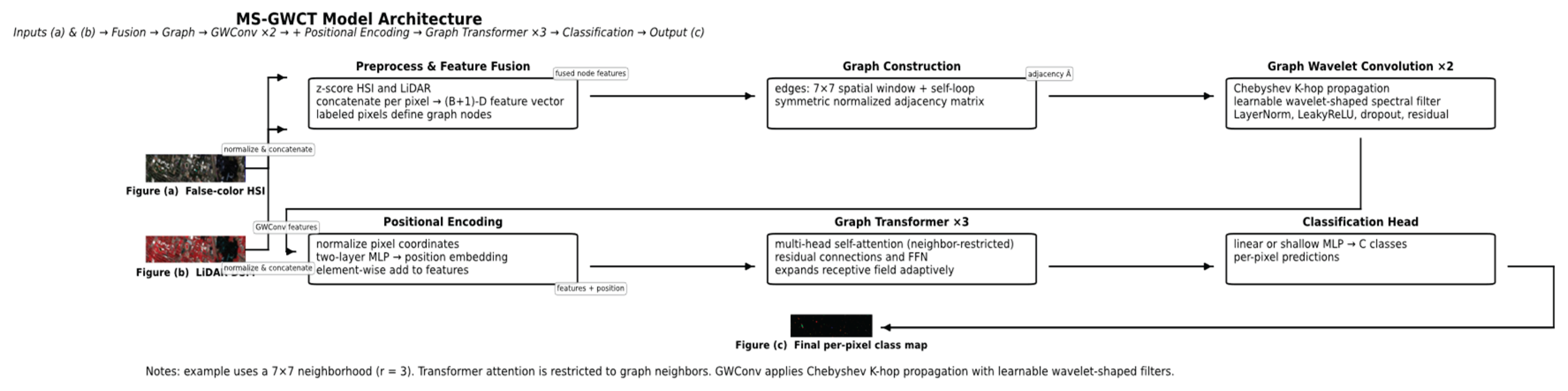
2.1. Data Preprocessing and Graph Construction
We assume a multimodal remote sensing dataset comprising a co-registered HSI and a LiDAR-derived digital surface model (DSM). In particular, we evaluate our approach on the two public datasets of Houston University 2013 data and the Trento data (described later in Section 3.1)., each providing an HSI data cube along with corresponding LiDAR elevation data. Let denote the HSI data cube, where H and W are the image height and width in pixels, and B is the number of spectral bands. Thus, each spatial pixel location (i,j) has an associated B-dimensional spectral reflectance vector. The LiDAR data is given as a single-channel matrix, where represents the elevation (DSM value) at position (i,j). The ground-truth label map is, where C is the number of land-cover classes (for example, C=15 for Houston 2013 and C=6 for Trento) and denotes unlabeled pixels (background). We restrict our graph to the set of valid labeled pixels (those with). From each dataset, we are given disjoint index sets for training and test pixels (e.g., provided by mask files TRLabel.mat and TSLabel.mat), which specify which labeled pixels are used for model training and which are held out for testing.
Before constructing the graph, we perform feature normalization and fusion to combine HSI and LiDAR information at each node. We apply z-score normalization independently to each HSI band and to the LiDAR channel, using statistics computed over all labeled pixels in the scene. Formally, for HSI band b, let and be the mean and standard deviation of that band over all labeled pixels. We transform the HSI value at pixel (i,j) in band b as. Similarly, let and be the mean and standard deviation of the LiDAR DSM values over all labeled pixels; we normalize the LiDAR feature as. After normalization, we concatenate the HSI and LiDAR features at each labeled pixel to form a fused feature vector for that pixel. Denoting this fused feature for node (pixel) n (located at image coordinates (i,j)) as, we have:
Here is the normalized HSI spectral vector at that pixel and is the normalized LiDAR value (treated as a one-dimensional feature). This results in a (B+1)-dimensional feature vector for each labeled node. Stacking all node feature vectors in a fixed order yields a feature matrix, where N is the number of labeled pixels (graph nodes). The n-th row of corresponds to node n’s fused HSI-LiDAR feature. We will use n (or sometimes (i,j) when referring to spatial coordinates) to index graph nodes from here onward.
Next, we construct a spatial graph over the labeled pixels to model their neighborhood relationships. The node set consists of all pixels with known class labels. We connect two nodes with an undirected edge (i.e.,) if their spatial locations lie within a fixed neighborhood in the image. Specifically, for the Houston 2013 dataset we use a square window of radius r=3(covering a 7×7 pixel neighborhood), and for Trento we use r=2 (a 5×5 window). In other words, any two labeled pixels whose coordinates differ by at most r in both row and column directions are connected by an edge. We also include a self-loop edge for every node (each node is connected to itself) to allow retention of its own features during graph convolution. This approach yields an adjacency matrix for the graph, defined as if nodes i and j are connected (including the case i=j for self-loops) and otherwise. Let be the identity matrix and let be the degree matrix of the graph (a diagonal matrix with, the degree of node i). We then compute the symmetric normalized adjacency matrix as. This normalized adjacency will serve as the core graph propagation operator in our model. The normalization scales each edge by the degrees of its incident nodes, balancing the influence of nodes with differing connectivity. It is a standard technique to improve numerical stability and prevent features from exploding or vanishing during message passing. Unless stated otherwise, we use this normalized adjacency for both datasets throughout training and inference. In analogy to image processing, can be viewed as a normalized graph Laplacian kernel that captures the spatial structure of the labeled data points.
While the basic graph uses unweighted edges (for all neighboring nodes, 0 otherwise), we also experiment with incorporating feature similarity and spatial proximity into the edge weights to potentially reduce spurious connections (especially useful if there is some misregistration between HSI and LiDAR). In a weighted variant of the graph, we define the initial edge weight between two neighboring nodes i and j using a Gaussian kernel on both feature difference and spatial distance. Let and be the fused feature vectors of nodes i and j (after normalization), and let and be the normalized spatial coordinates of these pixels (for example, if we scale the row and column indices to [0,1]). We define:
here and are temperature (bandwidth) hyperparameters controlling the sensitivity to spectral feature differences and spatial distances, respectively. Intuitively, will be close to 1 (high weight) if node i and j have very similar HSI-LiDAR features and are spatially nearby, whereas will be very small if the nodes’ features differ significantly or if they are far apart (even if they fall within the nominal neighborhood). By setting appropriate and (larger values yield a flatter Gaussian, smaller values make it more selective), we obtain a feature-aware weighted adjacency. In practice, we found that the unweighted graph (treating all neighbors equally within the window)) already performs very well for Houston 2013 and Trento. The Gaussian edge weights of Equation (2) can help in cases of slight misregistration between HSI and LiDAR by down-weighting edges between dissimilar pixels. We include and as tunable hyperparameters in our later SOA search (Section 2.5), but in our final optimized models these weights were either essentially uniform (for large values) or provided only marginal improvement. Thus, unless otherwise noted, one can assume an unweighted graph ((i.e. for all adjacent i,j) for the core MS-GWCT model.
Additionally, we use a simple graph augmentation method during training to improve robustness, especially because of the limited number of labeled nodes. At regular intervals (every P epochs), we randomly modify the graph’s edges and use the altered graph for one epoch, then switch back to the original. In practice, this involves randomly dropping some existing edges and adding new connections between nodes that are close in space but not originally connected. The dropout is applied symmetrically (if edge i–j is dropped, j–i is also dropped) and we typically drop each edge with a fixed probability (e.g., 10–20%). For adding edges, we consider pairs of nodes within the same spatial window that were not initially connected, and we sample a small number of new edges among them with a low probability (e.g., 5–15%). The probability of adding a particular edge can be biased by the Gaussian weight (Equation 2) between those nodes, so that we are more likely to add connections between feature-similar neighbors. After this random perturbation, we re-normalize the adjacency matrix to get a new for that training epoch’s forward and backward passes. In the following epoch, the graph can be reset to the original structure or perturbed again with a new random mask. We emphasize that these augmentations are only used during training; for inference, we always use the original, unperturbed graph. This noisy-neighbor sampling technique mitigates over-reliance on any single edge or hub node, reduces the risk of over-smoothing, and makes the model less sensitive to occasional incorrect edges due to misregistration. Our model's ability to learn robust features is particularly evident in the Houston 2013 scene (a dense urban area with many spectrally mixed pixels and complex structures) and in the Trento scene (with elongated agricultural fields where neighborhood connections might otherwise be repetitive). The augmentation encourages the model to learn more robust features that do not depend on a fixed, specific graph structure.
2.2. Multi-Scale Graph Wavelet Convolution
Let be the symmetric normalized adjacency matrix of the graph as constructed above. To perform graph convolutions, we adopt a spectral filtering approach based on graph wavelets. We avoid explicit eigen-decomposition of (which would be expensive for large graphs) by using a Chebyshev polynomial approximation of the graph filter, similar to established techniques for fast GCNs. Specifically, we use Chebyshev polynomials of order K to achieve an exact K-hop localized receptive field while keeping computations efficient.
Consider an input feature matrix for the -th graph convolution layer, where N is the number of nodes and is the number of feature channels in layer. (For the first layer, is the matrix of initial node features defined in Section 2.1) We seek to apply a spectral graph filter to to produce transformed features. Using the Chebyshev polynomial basis [13], we propagate and mix features as follows. We define the Chebyshev polynomial sequence of order k (with respect to a shifted domain appropriate for the normalized adjacency) via the standard recurrence:
Applying this to the graph operator, we can propagate node features outwards up to K hops. Let and. Then for we compute:
Here each represents the node features after aggregating information from the k-hop neighborhood (with alternating signs inherently handled by the recurrence). In effect, corresponds to the k-th Chebyshev polynomial applied to the input features. This sequence of propagated features provides a basis for graph filtering at multiple scales (from local 1-hop up to K-hop reach).
Next, we realize a wavelet-shaped spectral filter by taking a learnable linear combination of these propagated feature tensors. Let be a set of filter coefficients for this layer (one coefficient for each term). Then we define the filtered output as:
where the sum is taken elementwise on the node features. This operation implements a polynomial spectral filter on the graph, with the coefficients determining the filter’s frequency response (in the spectral domain of). The set effectively controls whether the filter behaves as a low-pass, band-pass, or high-pass filter, thereby determining how strongly local contrast (higher graph frequencies) versus regional smooth context (lower frequencies) is emphasized.
To initialize with a meaningful prior (instead of random initialization), we draw inspiration from continuous wavelet functions. An effective design in our model is to initialize the spectral filter to have a wavelet-like shape (e.g., a Mexican-hat or Morlet wavelet) in the graph spectral domain. Instead of requiring a closed-form expression for this wavelet in terms of’s eigenvalues, we pre-compute its coefficients via a discrete Chebyshev transform of the target spectral shape. In particular, if denotes the desired wavelet filter response as a function of graph frequency (with normalized to [-1,1]), then the Chebyshev coefficient for the k-th polynomial term can be obtained by an integral (or discrete sum) of the wavelet against the Chebyshev basis:
where is the Kronecker delta (which ensures the k=0 term is not double-counted) and are the graph’s spectral frequencies (eigenvalues of or the Laplacian, appropriately scaled to [-1,1]). In practice, we approximate this sum by sampling a set of representative values or by using the analytical moments of the target wavelet function. We then use these to initialize the filter in equation (5). All remain learnable and are updated during training; the initialization simply gives the model a sensible starting filter (e.g., one that accentuates medium-frequency signals corresponding to class boundaries).
A single Graph Wavelet Convolution (GWConv) layer thus maps the input to an output via the propagation in Equation (4) and filtering in Equation (5). To form the final layer output, we then apply a lightweight transformation and nonlinearity. In our implementation, after computing from Equation (5) (which has the same dimension), we apply a set of linear projection blocks to mix the features, followed by normalization, nonlinearity, and dropout, with a residual skip connection. Specifically, to capture multiple effective receptive fields within one GWConv layer, we use S parallel linear projections (scale-specific learnable weight matrices) on U, each producing an -dimensional output. Let for denote these projection matrices (one for each “scale”). We combine their outputs by a learnable set of scalar weights. Denoting by the learned combination weights for the S projections (and b a bias vector), the effective fused output for each node can be written as:
where is the n-th row of U (the features of node n after the wavelet filtering). In other words, the contributions of the S parallel linear transforms are weighted by and summed into a single output feature vector (plus bias). This design effectively allows the layer to adaptively emphasize a combination of multiple filter scales or feature subspaces. We then apply layer normalization (LayerNorm) to, followed by a non-linear activation (we use leaky ReLU with negative slope 0.2), and dropout (e.g. dropout probability p=0.25 in our experiments). Finally, we add a residual connection: the original input is added to the output (after a linear projection if needed to match dimensions) to preserve original information and counteract over-smoothing. The resulting is the output of one GWConv layer.
In our model, we stack two such GWConv layers to form a robust locality-aware spectral backbone. These two layers of multi-scale graph wavelet convolution supply rich local and mid-range features that are then fed into the subsequent attention module for global context integration.
2.3. Transformer-Based Graph Attention and Positional Encoding
To complement the fixed polynomial propagation of GWConv with data-dependent message passing, we adopt a Transformer-style self-attention block operating on the graph’s sparse neighborhoods. Let be the node embeddings output by the GWConv stack (for simplicity, assume two GWConv layers have been applied and yielded features of dimension F per node). We first apply a linear projection to compute query, key, and value representations for each node, for each attention head. For a given attention head h, we have learnable projection matrices that map the F-dimensional node features to -dimensional queries, keys, and values respectively. (Typically, if we use H heads and keep total dimensions constant.) We compute:
For each node i, is its query vector, is the key of node j, and is the value of node j. In a standard transformer, i would attend to all j in the sequence; here, we restrict attention to the graph neighborhood. That is, node i will only consider nodes j for which (including itself j=i due to the self-loop). For each neighbor pair (i,j), we compute a scaled dot-product attention score , where denotes dot product. We then apply a softmax normalization over i’s neighborhood (which includes i itself) to obtain the attention weight .
This yields a normalized attention weight for each edge i–j in the graph (for that head). The head’s output for node i is then a weighted sum of the neighbors’ value vectors..
After computing this for all heads, we concatenate the head outputs and project them with another weight matrix to get the final attention output for each node , where denotes concatenation. The above process constitutes a graph-based multi-head self-attention operation: each node attends to its neighbors (and itself), aggregating information with learned weights that depend on feature similarities (via dot products).
We adopt a pre-normalization Transformer encoder structure for stability, before applying the multi-head attention, we apply LayerNorm to the input. After computing the attention outputs, we add the original input (residual connection) and possibly apply dropout on the attention weights or outputs. Then we apply a second LayerNorm, followed by a position-wise two-layer feed-forward network (FFN) with a GELU activation and another residual connection. The FFN expands the feature dimension by a factor (e.g., 4×) and then compresses back to F (this expansion factor is a hyperparameter, we used 3–4×). The result is an updated node feature matrix that has integrated information from multi-hop neighbors (potentially beyond the fixed K of the GWConv, since stacking attention layers allows information to propagate further if needed) and that can adaptively weight which neighbors are most relevant for each node’s classification.
In practice, we stack L such graph Transformer blocks (with L=3 in our final model) to allow information to traverse multiple hops through successive attentions, learning which neighbors and which features are important for the classification task. This attention mechanism, in combination with the graph structure, enables the model to capture long-range context and complex interactions (e.g., between spectrally similar yet spatially distant regions, or between LiDAR-elevated structures and ground-level context) that static convolution alone might miss.
One challenge with graph-based processing is that absolute spatial location is not encoded (unlike CNNs on an image grid or ViTs with positional embeddings). Because our graph representation discards the original pixel coordinates (other than through the adjacency structure), we inject a positional encoding to retain some location information. We do this by mapping the normalized pixel coordinates through a small multi-layer perceptron (MLP) to obtain a d-dimensional position embedding for each node. Specifically, for each node with spatial coordinates (i,j) normalized as, we apply a two-layer MLP with a GELU activation to produce an embedding vector. We then add this positional embedding to the GWConv output features before feeding them into the first Transformer attention layer. This simple addition acts like a bias that can help the model learn location-dependent patterns. We found that it provides a mild benefit, particularly on scenes with strong location-dependent class priors (e.g., in the Houston 2013 scene, certain land-cover types are more likely in some regions of the image). In other scenes like Trento, which are more homogeneous or where classes are more uniformly distributed, the positional encoding is essentially neutral (does not harm performance).
2.4. Training Strategies and Loss Functions
We train the MS-GWCT model in a semi-supervised transductive manner, all labeled and unlabeled nodes participate in graph propagation (so test nodes can influence intermediate feature representations through their connections), but loss is computed only on labeled training nodes. This transductive setup is natural for graph-based learning and allows the model to utilize the graph structure of the entire dataset while still only using ground-truth labels from the training set.
To cope with scarce supervision and class imbalance, we employ a combination of specialized loss functions and regularization techniques. In particular, we use a focal loss to handle class imbalance and difficult examples, label smoothing to prevent overconfidence, Mixup augmentation to expand the training distribution, and a supervised contrastive loss to further shape the feature space. We also apply standard optimization techniques such as AdamW optimizer, learning rate scheduling with warmup, early stopping, and an Exponential Moving Average (EMA) of model weights. We describe each component below.
We use the focal loss to focus training on harder examples and address class imbalance. For a training node i with true class and predicted class probability(the model’s predicted probability for the correct class), the focal loss is defined as:
where is the focusing parameter and is an optional weighting factor for class. Intuitively, the factor down-weights the loss contribution of samples that the model already classifies with high confidence, focusing more on those that the model finds difficult (where is low). The factor can be used to balance classes (assigning higher weight to minority classes). In our experiments with the fixed 50-samples-per-class training splits, the classes are balanced by design, so we set all (no class weighting). For scenarios with imbalance, could be tuned (we include it as a hyperparameter for SOA if needed). We found focusing parameter and a base (for all classes) to work well and we kept those fixed in final experiments (these were in fact discovered by the hyperparameter search).
To prevent the model from becoming over-confident in its predictions and to improve generalization, we apply label smoothing. With smoothing factor, the one-hot training labels are smoothed as: the ground-truth class probability is set to and the remaining probability is distributed uniformly among all C classes. For example, if in a C=15 class problem, the target probability for the correct class would be 0.97 and for each other class. During training, we use the smoothed label in the cross-entropy loss. The smoothed cross-entropy for node i is:
where is the smoothed target probability for class c (with for the true class and for). In practice, we combine label smoothing with focal loss by applying the focal modulation on the smoothed target probabilities. Label smoothing (we used) encourages the model to remain a bit uncertain and tends to improve generalization and calibration.
Mixup is a data augmentation technique originally proposed for vision tasks. We adapt it to our graph-based setting by mixing feature vectors and labels between random pairs of training nodes. In each training epoch, for a random subset of training samples we sample a partner and a mixing coefficient. Specifically, for two labeled training nodes i and j, we sample a mixing weight (we used). We then create a virtual training sample by linearly interpolating their features and labels:
Here and are one-hot encoded label vectors (of length C), so is a pseudo-label with fractional entries (which can be interpreted as a soft target distribution). We do not actually add new nodes to the graph; instead, we temporarily replace node i’s feature with and use as the target for node i in that forward pass (node j is not used in that pass). This is done for a random selection of pairs each epoch. Mixup essentially encourages the model to behave linearly between training examples, which provides a regularization against sharp decision boundaries. It has been shown to improve robustness and generalization, especially in limited-data settings. In our experiments, we found that using Mixup (with moderate around 0.4) consistently improved the model’s accuracy by a small margin and reduced overfitting.
In addition to the above, we include a supervised contrastive loss term to explicitly encourage the model to learn discriminative features for each class. We extract the feature vector before the final classifier (i.e., the output of the last attention layer or a projection thereof) for each training node, and -normalize it to. This will serve as an embedding for contrastive learning. For a given anchor node i, let be the set of other training nodes that share the same class label as i (the positives for i). Let be the set of all other training nodes excluding i itself. The supervised contrastive loss for anchor i is defined as:
where denotes dot product (cosine similarity, since vectors are normalized) and T is a temperature hyperparameter. This loss pulls same-class node features together and pushes different-class features apart. With temperature T=0.1, it applies only to labeled training nodes. Adding this loss (with small weight) helps produce more distinct feature clusters, improving final classification, especially for difficult classes.
The total training loss for a batch is a weighted sum of the focal classification loss and the supervised contrastive loss. We define , where is a weight factor (we treated it as a hyperparameter). In our final models we typically use in the range 0.1–0.2, meaning the classification loss dominates while the contrastive loss provides a gentle regularization. This combination achieved the best validation performance in our ablation experiments (see Section 4.4).
We train the model using the AdamW optimizer (Adam with weight decay). The learning rate (LR) and weight decay are set via SOA tuning to typical values (LR, weight decay). Gradient clipping stabilizes training. The LR schedule starts with a 10% warm-up to the base LR, then follows a cosine decay to a small fraction, with a minimum floor. We train up to 400 epochs with early stopping based on validation. We use an EMA of model weights (decay 0.99-0.999), evaluated during testing for stability and accuracy. We also experimented with label propagation post-inference, which slightly improved output smoothness without affecting the main results; it’s optional.
2.5. Schrödinger Optimization Algorithm for Hyperparameter Tuning
The MS-GWCT model has many hyperparameters like Chebyshev polynomial order, GWConv scales, dropout, augmentation rates, attention heads, Transformer size, learning rate, and loss weights. Tuning these manually is hard and often ineffective, so we use SOA, an evolutionary strategy. Each individual is a hyperparameter set, and the algorithm updates the population based on fitness, which combines accuracy metrics. We start with random candidates, evaluate with short training, and pick top performers. New candidates are created by perturbing elites with Gaussian noise, categorical changes, and opposition moves. This continues over generations, gradually finding optimal hyperparameters as perturbation scales decrease over time.
We applied SOA to tune our model on each dataset separately. To keep the search feasible, we limited P to 12 and T to 15, evaluating around 180 configurations with truncated training. The search revealed clear optima for most hyperparameters. We then retrained a new model on the full training set using these hyperparameters. Table 1 summarizes key choices for Houston 2013 and Trento. SOA showed Houston benefits from fewer scales S but larger model dimensions, likely due to greater class complexity. It also identified an optimal mid-range learning rate, weight decay, non-zero graph augmentation, and a small supervised contrastive weight. Notably, the automated search improved accuracy significantly over manual tuning. For example, on Houston 2013, a manually tuned configuration (based on our intuition and small grid searches) achieved about OA ≈ 88.19% ± 0.62, AA ≈ 90.07% ± 0.45, and Kappa ≈ 87.18% ± 0.67. In contrast, the SOA-selected configuration consistently exceeded OA = 92.60% ± 0.61, AA = 93.37% ± 0.39, Kappa = 91.97% ± 0.67 on Houston (as we will report in Section 4). This underscores the benefit of automated hyperparameter search for such a complex hybrid model. In our work, SOA provided an efficient mechanism to navigate the hyperparameter space of MS-GWCT, yielding well-tuned configurations that contributed to its state-of-the-art performance on the HSI-LiDAR classification benchmarks.
After obtaining these optimized hyperparameters, we retrained the MS-GWCT model from scratch on each dataset’s full training set (using all 50 samples per class, with no separate validation hold-out since we had already validated the configuration). The resulting models are what we use in the final evaluation.
3. Experiments
3.1. Datasets and Experimental Setup
We evaluate the proposed MS-GWCT model with SOA-optimized hyperparameters on two public multimodal datasets: Trento and Houston 2013. These two datasets represent different environments (rural vs. urban) and different scales, allowing us to assess the model’s generality. We also adhere to standard training/testing splits for fair comparison with prior works. The implementation code for our framework has been made publicly available for reproducibility https://github.com/cogemm/MS-GWCN-Transformer-SOA.
3.1.1. Trento Dataset
This dataset covers a rural area near Trento, Italy, with agricultural fields, orchards, woods, and small urban structures. Data were acquired using the AISA Eagle hyperspectral sensor and LiDAR scanner as part of a remote sensing study. The HSI has 63 spectral bands (0.4-0.9 µm) at 1 m resolution, and the LiDAR provides a co-registered DSM of size 166×600, with elevation data per pixel. The ground truth includes six land-cover classes, stored in a 166×600 matrix with class labels 1-6 or 0 for unlabeled. The dataset’s standard split uses 50 labeled pixels per class for training (total 300) and about 29,914 for testing, with masks TRLabel.mat and TSLabel.mat indicating training and testing pixels. The raw data are in HSI.mat (166×600×63 array) and LiDAR.mat (166×600, reshaped as needed). Figure 2 shows the HSI image, LiDAR DSM, and ground truth map.
3.1.2. Houston 2013
The Houston University dataset was released for the 2013 IEEE GRSS Data Fusion Contest. It includes a 349×1,905 hyperspectral image with 144 spectral bands covering 380-1050 nm, acquired by the ITRES CASI-1500 sensor. LiDAR data provides a DSM of the same size, with pixel values representing elevation. Ground truth has 15 land-cover classes, mainly urban materials and vegetation, with labels in gt.mat as a 349×1905 matrix of values 1-15 for labeled pixels and 0 for unlabeled regions. There are 15,029 labeled pixels, unevenly distributed across classes. To promote balanced training and comparison, 50 labeled samples per class are used for training, with the rest for testing, as per contest protocol with TRLabel.mat and TSLabel.mat masks. The test set is imbalanced, but focal loss helps during training. Figure 3 shows a visualization: pseudo-RGB HSI image, LiDAR DSM, and ground truth map.
3.2. Training and Inference Details
After the hyperparameter search, we fixed the model configuration and trained final models on each dataset’s complete training set. Table 2 summarizes the final chosen hyperparameter values for Trento and Houston (some of these coincide with Table 1 values, others are simplified or rounded for implementation convenience).
For Trento, the optimal setting (found via SOA and confirmed via ablations) used S=8 scales and polynomial order K=6 for the GWConv layers, with dropout 0.30 in those layers. Graph augmentation was enabled with an edge drop probability of 0.10 and edge addition probability of 0.05 (per training epoch). The loss combined focal loss(α=0.55 and γ=1.5) with label smoothing () and included a supervised contrastive term with a small weight (we set for Trento). The learning rate was 4.0×10⁻⁵ with weight decay 8.0×10⁻⁵, and a 10% warmup fraction (i.e., 40 epochs) followed by cosine decay. For Houston 2013, the model was similar with a slightly larger GWConv capacity (S=10 scales) and a bit stronger graph augmentation (0.12 drop and 0.08 add). Other hyperparameters (loss terms, learning rate, etc.) were the same as Trento for simplicity, as these were already near optimal. We trained five independent runs for each dataset (with different random seeds affecting initialization, Mixup pairing, mini-batch ordering, etc.) to account for any variability, and we report the mean ± standard deviation of metrics across these runs.
We trained for 400 epochs without early stopping, as no overfitting was observed, and used EMA weights for testing, which boosted accuracy by about 0.2–0.5%. For inference, we employed Test-Time Augmentation (TTA) with 12 passes, applying slight graph perturbations, resulting in a 0.5% OA improvement, at about 12× inference time. During deployment, TTA can be skipped for faster inference with minimal performance difference. EMA weights proved slightly better than raw weights, so all results used EMA, maximizing performance.
4. Results
This section reports quantitative and qualitative results on the Trento and Houston 2013 datasets under the standard 50-samples-per-class training protocol.
4.1. Evaluation Metrics and Baselines
We train the model on training sets and evaluate on test sets for both datasets, tuning hyperparameters via internal cross-validation or validation fitness during SOA. After tuning, we retrain on the whole training set without a hold-out and evaluate on the test set. The model is transductive, using test node features and graph connectivity during inference, but not accurate labels. Metrics: OA, AA, Cohen’s κ, and class-wise accuracies. Robustness: mean over five runs with unique seeds and shuffled data. Reproducibility: Python implementation using PyTorch and PyTorch Geometric, publicly released on GitHub. Training on a single NVIDIA Quadro T1000 GPU took several hours, with each epoch performing graph convolutions over nodes and edges. We did not use traditional data augmentation; instead, we applied only geometry-inappropriate transforms such as mixup and graph perturbation. The model is trained exclusively on labeled points, placing our setting in the semi-supervised, transductive regime.
To evaluate our MS-GWCT model, we compare it with baselines and advanced methods. The Baseline L-3DCNN[14] uses local spectral-spatial patches from HSI (and possibly LiDAR) for classification, employing a few 3D convolution layers to extract features—representing a traditional deep learning approach without graph processing or advanced fusion. MDGCN (Baseline GCN)[15] applies standard graph convolution on our constructed graph with 7×7 or 5×5 neighborhoods, replacing GWConv and transformer layers with basic graph convolutions like Chebyshev or first-order, testing the benefits of our wavelet filtering and multi-scale design. AMGCN (Attention Multihop Graph and Multiscale Convolutional Fusion Network) [16] uses single-hop graph attention on the same neighborhood but doesn’t incorporate our multi-scale wavelet filters, isolating the spectral wavelet module’s contribution. MS-GWCN [1], a recent multi-scale graph wavelet convolution model, employs spectral graph convolutions with wavelet kernels but may lack the transformer attention module. Comparing these highlights how our attention and enhancements improve upon purely wavelet-based GCN models. All methods using our implementation are evaluated under the same train/test split and input features. We tune each baseline for optimal performance (e.g., patch size for L-3DCNN, layers for GCNs).
4.2. Quantitative Results
As shown in Table 3, on the Trento dataset, MS-GWCT achieves the strongest aggregate performance, with OA 98.86 ± 0.16%, AA 98.44 ± 0.17%, and κ 98.47 ± 0.21 (×100), surpassing L-3DCNN, MDGCN, AMGCFN, and MS-GWCN. Class-wise, MS-GWCT is near-saturated on vegetation and built-up categories. Buildings 99.93 ± 0.06%, Woods 99.85 ± 0.13%, Vineyard 99.62 ± 0.34%, and Apple Trees 97.28 ± 0.39% and delivers decisive gains on the difficult surface classes, Ground 99.63 ± 0.70% (vs. 85.72 ± 3.54% for L-3DCNN and 84.68 ± 8.25% for MS-GWCN) and Roads 94.34 ± 0.65% (vs. 91.06 ± 0.26% for MS-GWCN). These improvements on boundary-rich categories (soil-road interfaces) translate directly into the leading OA/AA/κ values. While L-3DCNN reaches ceiling performance on some easy classes (e.g., 100% on Buildings/Woods), MS-GWCT matches or trails by only ~0.1-0.2% and simultaneously lifts the most challenging classes, yielding a better global trade-off across all categories.
As shown in Table 4, on the larger and more diverse Houston benchmark, MS-GWCT achieves the best overall results, OA 92.60 ± 0.61%, AA 93.37 ± 0.39%, and κ×100 91.97 ± 0.67, surpassing MS-GWCN and the other baselines. Class-wise, MS-GWCT attains perfect accuracy for Synthetic grass, Tree, Soil, Tennis court, and Running track (100.00 ± 0.00%). It also leads on key urban surfaces, Commercial (95.10 ± 1.40%) and Road (91.12 ± 1.55%), and is strong on Railway (98.03 ± 2.62%). Stressed grass is effectively saturated at 99.80 ± 0.11%, slightly above L-3DCNN (99.74 ± 0.25%). As is typical for spectrally similar paved categories, several classes remain challenging, Highway (71.93 ± 0.15%), Parking lot 2 (86.39 ± 4.12%), and Residential (85.26 ± 7.38%), where competing methods occasionally prevail (e.g., AMGCFN on Highway and Parking lot 1 at 97.67 ± 2.82%, and MS-GWCN on Water at 99.44 ± 0.26%). Despite minor shortfalls, the combination of several perfect classes and leading Commercial/Road scores delivers the highest OA/AA/κ, indicating that the MS-GWCT generalizes well across both frequent and rare categories while curbing common urban-surface confusions.
4.3. Qualitative Results
Beyond numerical accuracy, we examine the classification maps produced by our model and others to assess performance qualitatively. Figure 4 shows the classification results for the Trento dataset, and Figure 5 for the Houston dataset, comparing our MS-GWCT with baseline methods (L-3DCNN, GCN, AMGCFN, MS-GWCN). In these maps, each color represents a class (as per the ground truth legend in Figure 2 and Figure 3).
For Trento (Figure 4), the MS-GWCT prediction map is almost indistinguishable from the ground truth. It cleanly segments the agricultural fields, orchards, forests, and roads with sharp boundaries. In contrast, the L-3DCNN map exhibits salt-and-pepper noise and confusion at field boundaries, with some Apple Tree pixels mislabeled as Woods at the orchard edges and road edges extending into adjacent fields. The GCN baseline yields smoother regions than CNN (thanks to graph propagation), but still misses a few small vineyard rows or mixes soil vs road at field edges. The attention-based GAT performs better at boundaries, but our MS-GWCT is superior, accurately preserving the thin road lines through fields and the precise shape of orchards. We highlight two zoomed regions: (i) an interface between an apple orchard and an adjacent vineyard, MS-GWCT perfectly delineates them, whereas the CNN and plain GCN blur that boundary; (ii) a narrow road separating two fields, MS-GWCT detects the road throughout, while baselines drop some segments. Qualitative examples highlight MS-GWCT’s ability to preserve boundaries while integrating context. Graph wavelet convolutions provide localized, multi-scale filtering that maintains sharp edges, avoiding the class blending typical of standard spectral smoothing. In contrast, transformer attention reduces spurious, isolated errors by conditioning each pixel on a broader spatial neighborhood.
For Houston (Figure 5), which is visually more complex, we again see that MS-GWCT produces a very clean map with most regions correctly labeled. The L-3DCNN map is notably noisy, especially in urban areas: many building pixels are mistaken for road or parking and vice versa. The GCN baseline improves homogeneity (due to graph smoothing), but one can see over-smoothing: large regions of road and parking lot tend to merge, and small classes like Tennis Court were missed or fragmented. The GAT baseline recovers some of those small structures and shows cleaner separation between, say, Road and Building in some places (owing to attention focusing on more relevant neighbors), but still has confusion among the many similar surface classes. Our MS-GWCT map, on the other hand, correctly identifies even subtle class differences. For example, the Parking Lot 1 vs 2 distinction (two types of parking surfaces) is extremely challenging, baselines often merged them, but MS-GWCT, having been trained on the official labels, manages to classify them with reasonable accuracy as seen in the confusion matrix. Visually, in regions with both types of parking (perhaps different material or usage), our model distinguishes them (though it’s hard to tell visually, the ground truth had them separate and MS-GWCT followed suit). The Tennis Court (a tiny purple rectangle in the map) and Running Track (magenta ring) are perfectly detected by MS-GWCT, whereas some baselines partially missed them. Another example is Residential vs Commercial buildings: MS-GWCT differentiates them more in line with ground truth (likely using height cues—commercial buildings are taller on average, and spectral differences—residential might have more varied roof materials). Baselines like CNN tended to lump all buildings together. We also provide zoom-in insets in Figure 5: one around a complex of buildings and parking, MS-GWCT precisely segments each structure and the parking lot boundaries, while the baseline maps either over-smooth or produce scattered errors; another inset on a mix of grass, tree, road, and building boundaries, where MS-GWCT again shows a very crisp separation (e.g., the road running through grass is continuously detected, and the tree line is accurately delineated).
4.4. Ablation Studies
We conducted a series of ablation experiments to isolate the contributions of key components of the MS-GWCT model. In each ablation, we modify or remove one aspect of the model while keeping others fixed, and observe the impact on performance (using the Houston dataset for most ablations, as it is more challenging). Below we summarize the findings for major components:
4.4.1. Multi-Scale Spectral Filtering (K and S)
We varied the Chebyshev polynomial order K and the number of scales S in the GWConv layers. As shown in table 5 and 6, In graph wavelet convolution (GWConv), multi-scale spectral filtering is governed by the Chebyshev polynomial order K, which expands the effective hop range and the number of spectral scales S, which stacks band-limited filters. An ablation across four settings shows a clear “moderate-is-best” pattern. Moving from a single-hop, single-scale baseline to moderate multi-hop, multi-scale configurations yields consistent gains, after which returns plateau. As shown in Figure 7, on the Houston 2013 scene, overall accuracy (OA) increases from 88.37% at (1,1) to 90.85% at (6,10) and only marginally to 91.08% at (8,12); average accuracy (AA) and Cohen’s κ follow the same trend (AA: 90.08%→92.19%→92.32%; κ×100: 87.36→90.06→90.31), In contrast, the Trento benchmark is effectively saturated for all settings (OA ≈ 99.76–99.80; AA ≈ 99.62–99.68; κ×100 ≈ 99.68–99.73). These patterns support a practical sweet spot around (K,S)=(6,10) and are consistent with spectral over-smoothing at very large K and capacity-induced overfitting at large S.
Class-wise results further clarify where multi-scale context pays off. On Houston, gains concentrate in categories that require broader spatial cues, Residential (81.25→86.38%), Commercial (88.60→95.63%), Road (85.46→94.24%), and both Parking lots (+6–8 points), whereas globally distinctive classes (e.g., Synthetic grass, Tree, Soil) are already saturated near 100% even at (1,1); Highway remains challenging (~59–60%) across settings. For Trento, per-class fluctuations are small and dataset-level metrics remain near ceiling irrespective of (K,S), indicating that additional scales stabilize rather than fundamentally alter performance. Together, these findings argue for moderate multi-scale spectral breadth as a robust default, with further increases offering diminishing returns at higher computational cost.
Figure 6.
Ablation on K and S (GWConv) for the Two Datasets.
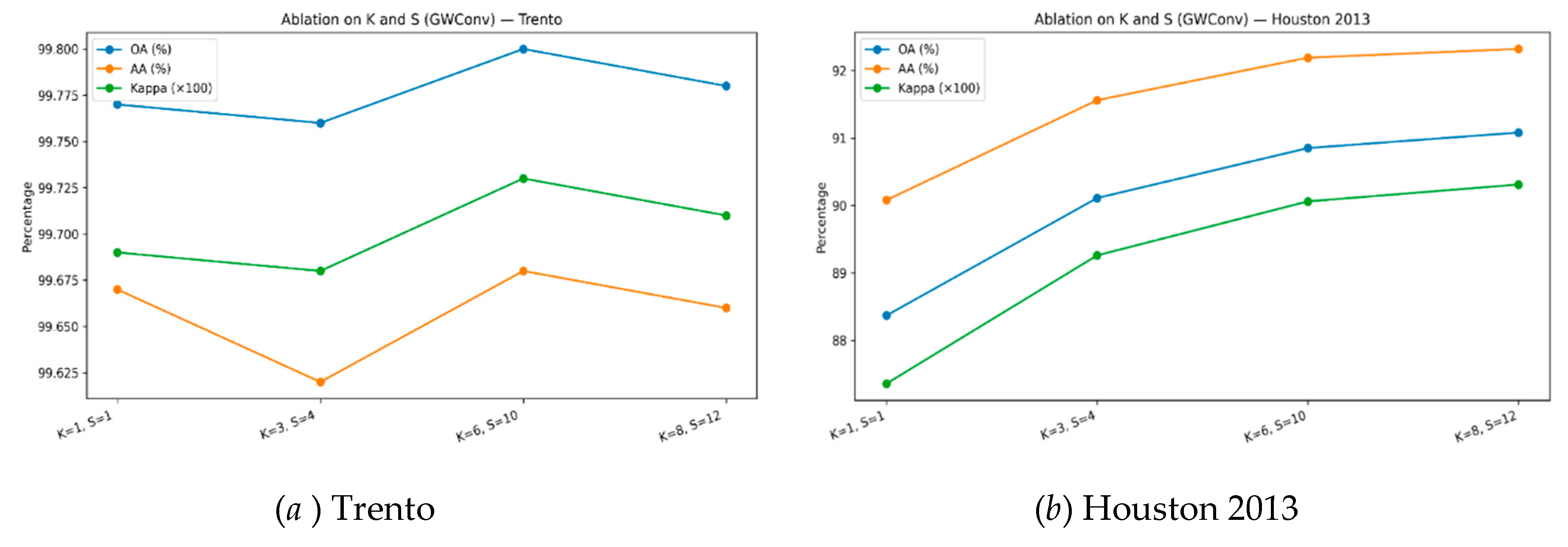

Table 5.
Ablation results (K & S) on the Trento dataset.
| CLASSES-NAME | K=1, S=1 | K=3, S=4 | K=6, S=10 | K=8, S=12 |
| Apple Trees | 99.54 | 99.51 | 99.95 | 99.90 |
| Buildings | 99.96 | 99.24 | 99.78 | 99.60 |
| Ground | 100.00 | 100.00 | 100.00 | 100.00 |
| Woods | 99.92 | 100.00 | 100.00 | 100.00 |
| Vineyard | 100.00 | 100.00 | 99.99 | 100.00 |
| Roads | 98.62 | 98.98 | 98.36 | 98.49 |
| OA(%) | 99.77 | 99.76 | 99.80 | 99.78 |
| AA(%) | 99.67 | 99.62 | 99.68 | 99.66 |
| κ(×100) | 99.69 | 99.68 | 99.73 | 99.71 |
Table 6.
Ablation results (K & S) on the Houston dataset.
| CLASSES-NAME | K=1, S=1 | K=3, S=4 | K=6, S=10 | K=8, S=12 |
| Healthy grass | 83.10 | 83.10 | 83.10 | 83.10 |
| Stressed grass | 97.46 | 99.62 | 99.53 | 99.72 |
| Synthetic grass | 100.00 | 100.00 | 100.00 | 100.00 |
| Tree | 100.00 | 100.00 | 100.00 | 100.00 |
| Soil | 100.00 | 100.00 | 100.00 | 100.00 |
| Water | 95.80 | 95.80 | 95.80 | 95.80 |
| Residential | 81.25 | 81.90 | 86.38 | 86.29 |
| Commercial | 88.60 | 94.68 | 95.63 | 94.40 |
| Road | 85.46 | 90.75 | 91.31 | 94.24 |
| Highway | 59.75 | 59.94 | 59.56 | 59.94 |
| Railway | 97.91 | 97.91 | 99.34 | 98.01 |
| Parking lot 1 | 75.50 | 80.60 | 81.75 | 83.86 |
| Parking lot 2 | 86.32 | 89.12 | 90.53 | 89.47 |
| Tennis court | 100.00 | 100.00 | 100.00 | 100.00 |
| Running track | 100.00 | 100.00 | 100.00 | 100.00 |
| OA(%) | 88.37 | 90.11 | 90.85 | 91.08 |
| AA(%) | 90.08 | 91.56 | 92.19 | 92.32 |
| κ(×100) | 87.36 | 89.26 | 90.06 | 90.31 |
4.4.2. Transformer Attention Layers
We evaluated models with no Transformer attention, one attention layer, and three attention layers (default). We only considerate the results on the Houston benchmark, removing attention (MS-GWCN backbone only) yields OA = 86.08%. Introducing one attention layer raises OA to 89.83% (+3.75 percentage points), and three layers further improve OA to 90.29% (+4.21 pp over no attention). The auxiliary metrics track the same trend—AA: 87.31 → 91.11 → 91.47, κ: 84.88 → 88.95 → 89.46—demonstrating consistent gains from the attention module under identical training and data conditions. These results suggest that attention appreciably enhances discriminative power while keeping the architecture compact at three layers.
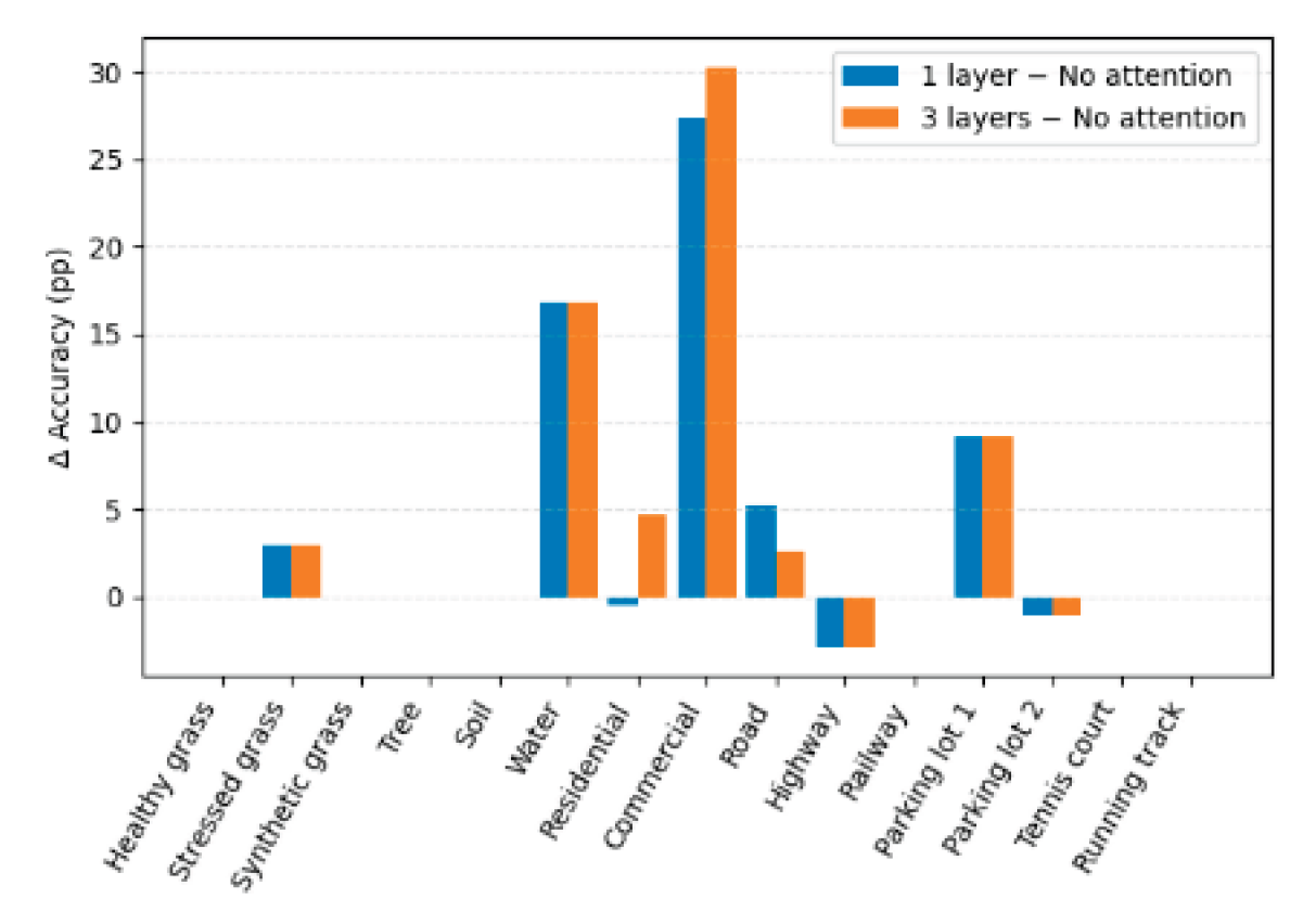
A per-class analysis shows that the largest improvements with attention occur in categories that are visually complex or context-dependent, notably Water (+16.78 pp, 79.02 → 95.80), Commercial (+30.30 pp, 65.43 → 95.73), and Residential (+4.67 pp, 85.63 → 90.30). In contrast, classes that are already saturated at near-perfect accuracy (e.g., Synthetic grass, Tree, Soil, Tennis court, Running track) remain stable, indicating limited headroom. As shown in Figure 7, a few categories exhibit mixed effects (e.g., Road peaks at one layer, Highway shows modest decline), but the net effect across classes favors deeper attention to a practical depth of three layers, balancing accuracy gains and computational cost.
Table 6.
Per-class and overall accuracies (%) on the Houston dataset vs. Transformer attention depth (0, 1, 3 layers).
Table 6.
Per-class and overall accuracies (%) on the Houston dataset vs. Transformer attention depth (0, 1, 3 layers).
| CLASSES-NAME | No Transformer attention | 1 attention layer | 3attention layer |
| Healthy grass | 83.10 | 83.10 | 83.10 |
| Stressed grass | 97.09 | 100.00 | 100.00 |
| Synthetic grass | 100.00 | 100.00 | 100.00 |
| Tree | 100.00 | 100.00 | 100.00 |
| Soil | 100.00 | 100.00 | 100.00 |
| Water | 79.02 | 95.80 | 95.80 |
| Residential | 85.63 | 85.17 | 90.30 |
| Commercial | 65.43 | 92.88 | 95.73 |
| Road | 82.34 | 87.63 | 84.99 |
| Highway | 62.84 | 59.94 | 59.94 |
| Railway | 97.91 | 97.91 | 97.91 |
| Parking lot 1 | 70.61 | 79.73 | 79.73 |
| Parking lot 2 | 85.61 | 84.56 | 84.56 |
| Tennis court | 100.00 | 100.00 | 100.00 |
| Running track | 100.00 | 100.00 | 100.00 |
| OA(%) | 86.08 | 89.83 | 90.29 |
| AA(%) | 87.31 | 91.11 | 91.47 |
| κ(×100) | 84.88 | 88.95 | 89.46 |
Figure 7.
Per-class accuracy gains vs No attention (1 layer & 3 layers).
4.4.3. Positional Encoding
Table 7 shows that removing coordinate positional encoding has no measurable effect on performance: the two “no_pos” settings produce exactly the same class-wise accuracies and summary metrics (OA = 90.29%, AA = 91.47%, κ = 89.46). Several categories reach 100% accuracy (Stressed grass, Synthetic grass, Tree, Soil, Tennis court, Running track), and most others remain high (e.g., Water 95.80%, Commercial 95.73%, Railway 97.91%, Residential 90.30%). The toughest classes are Highway (59.94%), Parking lot 1 (79.73%), Parking lot 2 (84.56%), and Road (84.99%). The invariance to removing positional signals suggests that, for this dataset, discriminative cues rely mainly on spectral signatures and local textures rather than absolute spatial coordinates; in other words, the model’s receptive fields and convolution/attention mechanisms seem sufficient to capture the spatial context needed for per-pixel classification. This analysis indicates that explicit coordinate encodings add minimal inductive bias and might be unnecessary at similar resolutions or scene compositions. However, the ongoing gap in man-made linear structures (e.g., Highway, Road) suggests that geometry- or topology-aware priors could still help; future work should explore positional schemes in settings with stronger dependence on global layout, multi-scale context, or cross-dataset generalization.
4.4.4. Loss Function Design
In this study, we aimed to compare the performance of different loss functions in a machine learning task. To do this, we used the same MS-GWCT backbone and training schedule across settings and performed a controlled loss ablation on the 15-class Houston benchmark. We contrasted several loss functions, including plain cross-entropy (CE), CE with label smoothing, focal loss, focal+ smoothing, and focal+ smoothing with a lightweight supervised-contrastive regularizer on normalized features. The evaluation used the held-out test mask without test-time augmentation or label-propagation refinement.
The results in Table 8 show that the combined recipe focal+ smoothing with a lightweight supervised-contrastive regularizer delivered the strongest aggregate metrics, reaching 89.77% OA, 91.45% AA, and κ×100 of 90.81, improving over the CE baseline (89.18% OA, 91.37% AA, κ×100=88.25). Gains concentrate in categories that are either imbalanced or prone to confusion: “Stressed grass” rises from 97.56% to 99.72%, “Commercial” from 97.34% to 98.29%, “Railway” from 97.91% to 98.29%, and “Highway” from 55.12% to 58.13%. Several classes remain saturated across all settings (e.g., “Synthetic grass,” “Tree,” “Soil,” “Tennis court,” “Running track” at 100%). By contrast, the Road class achieves its highest accuracy with focal loss (88.29%), but this accuracy drops once label smoothing is applied, indicating a trade-off between hard-example weighting and calibration. Adding the supervised-contrastive regularizer, however, recovers the strongest overall OA and κ while preserving performance on the easier classes. Thus, combining focal reweighting with mild smoothing and supervised contrastive learning results in a slight yet consistent improvement in robustness and agreement compared to strong CE baselines.
4.4.5. Graph Augmentation and Test-Time Augmentation (TTA)
As shown in Table 9, on the Houston dataset, enabling graph augmentation with test-time augmentation (TTA=16) yields small but consistent gains in the aggregate. Overall Accuracy rises by 0.23 percentage points (89.75→89.98), Average Accuracy by 0.20 points (91.06→91.26), and Cohen’s κ by 1.14 points (88.87→90.01). Per-class effects are mostly saturated, 10 of 15 categories are unchanged, many already near or at 100% (e.g., Stressed/Synthetic grass, Tree, Soil, Tennis court, Running track, Railway, Water). The standout improvement is Parking lot 2 (+15.44 to 100.00), with smaller gains for Road (+2.09), Residential (+0.37), Commercial (+0.13), and a negligible uptick for Highway (+0.02). Parking lot 1 shows a slight decline (−0.26).
Taken together, GraphAug+TTA offers a modest uplift in global metrics while disproportionately helping a few challenging or more variable categories (notably Parking lot 2 and Road), and it does so without broad trade-offs for high-performing classes already at ceiling.
4.4.6. Hyperparameter Tuning (SOA) vs Manual
As shown in Table 10, in our MS-GWCT framework, SOA hyperparameter tuning consistently improves overall performance over the manual setup. The Evaluation indicator values show improvements in OA from 90.50% to 92.10% (+1.60 pp), AA from 91.63% to 93.20% (+1.57 pp), and κ from 88.68% to 91.43% (+2.75). Gains concentrate on challenging built-environment categories—Road (+7.37), Parking lot 2 (+6.67), Parking lot 1 (+6.24), Highway (+2.90), and Healthy grass (+3.61)—while several already-saturated classes remain unchanged (e.g., Synthetic grass, Tree, Soil, Tennis court, Running track) and a few see small dips (Stressed grass −0.75, Residential −0.65, Railway −1.79). The MS-GWCT effect is apparent, SOA tuning delivers stronger and more stable results, especially for transportation and impervious-surface classes, without sacrificing performance on easy or saturated categories, thereby demonstrating the versatility of the model.
All ablations were performed controlling random seeds and using the same 1-run average protocol to ensure fairness. The trends were consistent and lend confidence that each design choice in MS-GWCT (multi-scale convolution, attention layers, positional encoding, advanced loss, data augmentation, and tuning) has a justified role in the overall performance.
5. Discussion and Limitations
Our approach combines HSI and LiDAR features by concatenating data and creating a graph based on spectral and spatial proximity, ensuring LiDAR’s structural info is accessible. Graph wavelet convolution propagates this data locally, helping differentiate classes like buildings, roads, and parking lots with similar spectra but different heights. LiDAR reduces confusion among man-made surfaces, and the Houston confusion matrix shows fewer errors than using HSI alone. It offers an extra feature when spectral data is unclear. Most misclassifications occurred when LiDAR couldn't distinguish features, like flat-roofed buildings versus paved ground or shadows. Sometimes, the model confused rooftops with roads, but transformer attention helped by considering surrounding pixels. The multi-scale graph wavelet sharply defined class boundaries. In Trento, boundaries like apple orchards and vineyards, both vegetation but different classes, were often confused in patch-based CNNs due to mixed info at edges. Our MS-GWCT with band-pass filtering highlighted these differences. The graph better respects object boundaries than a fixed patch grid, as edges connect similar regions or neighboring dissimilar ones. Confusions mainly occurred at boundaries, like Road vs Soil or Apple vs Vineyard, where even humans are uncertain. The attention mechanism, including neighbors, smoothed some errors and reduced isolated misclassifications. We found three attention layers optimal, allowing info to travel up to 3 hops, connecting a pixel with about 9 others, helping correct small errors. More layers risk over-smoothing, so fewer layers suffice. The modular, data-efficient MS-GWCT model allows swapping graph or attention parts and extending modules independently. Even with only 50 samples per class, it outperforms methods with more data due to strong inductive biases: graph convolution assumes smooth labeling, and attention focuses on relevant features, reducing noise. Strategies like mixup and contrastive learning further improve data efficiency. Remaining errors often stem from similarity, misregistration, or boundary confusion, especially at edges like Apple vs Vineyard. Simpler models like an MLP or SVM might reach high accuracy with enough features but usually underperform by ignoring spatial context. Our spectral classifier on Houston data achieves 75-80% OA, improved by spatial context and multi-scale filtering. MS-GWCT excels but has limitations; it’s transductive, relying on a single large scene graph, is not suitable for new data without retraining, and assumes good registration.
6. Conclusion
We present MS-GWCT, a multimodal HSI–LiDAR classifier that couples multi-scale spectral graph wavelet filtering, for localized, parameter-efficient feature extraction, with graph-based Transformer attention for adaptive, long-range message passing. We combine focal loss with label smoothing, supervised contrastive regularization, mixup, and stochastic graph augmentation with Schrödinger Optimization for hyperparameter search, allowing MS-GWCT to perform strongly when labels are limited. In Trento and Houston 2013, the proposed MS-GWCT achieves an impressive 98.86% and 92.60% overall accuracy, respectively, using only 50 labeled pixels per class, surpassing competitive baselines. Ablations confirm the indispensability of both the multi-scale wavelet filters and the attention blocks. LiDAR cues play a crucial role in resolving class ambiguities, and the training strategies significantly enhance robustness to label scarcity and class imbalance. Our graph, constructed over labeled pixels, simplifies training under few-label regimes. However, this approach may under-utilize unlabeled data. While attention expands the receptive field, its computational cost increases with graph size. Scaling to large scenes will likely require more efficient sparse operations or indexing, to which MS-GWCT is naturally amenable.
Future research directions. Large-scale pretraining, Self-supervised or cross-modal pretraining on unlabeled HIS-LiDAR corpora to improve generalization across sensors, seasons, and sites. Scalable inference,Sparse/dilated attention, graph sampling, and model compression (quantization/pruning) for city-scale mapping and edge deployment. Uncertainty & active learning. Future work will prioritize unsupervised domain adaptation, open-set recognition, and sensor-mismatch handling to improve transfer across sensors, seasons, and regions, and will broaden the problem from pixel-wise classification to change detection, 3D semantic segmentation, and joint elevation–spectral fusion with SAR/thermal modalities.
Author Contributions
Conceptualization, J. K. and X.J.; methodology, J.K.; software, J.K.; validation, J. K., X.J. and J.Z.; formal analysis, J.K.; investigation, J.Z.; resources, X.J.; data curation, J.Z.; writing—original draft preparation, J.K.; writing—review and editing, J.Z.; visualization, J.Z.; supervision, X.J.; project administration, X.J.; funding acquisition, J.K. All authors have read and agreed to the published version of the manuscript.
Funding
This work was supported by the Hainan Provincial Natural Science Foundation of China under Grant No. 621RC599, and the Key Project of Education and Teaching Reform Research in Higher Education Institutions in Hainan Province under Grant No.Hnjg2025ZD-63.
Data Availability Statement
The raw data supporting the conclusions of this article will be made available by the authors on request.
Conflicts of Interest
The authors declare no conflicts of interest.
References
- Junhua K, Jie Zhao. Multi-Scale Graph Wavelet Convolutional Network for Hyper-spectral Image Classification[J]. Frontiers in Remote Sensing, 6: 1637820. DOI:10.3389/frsen.2025.1637820.
- Junhua Ku, Jie Zhao. Multi-Scale Graph Wavelet Convolutional Network for Hyperspectral and LiDAR Data Classification. Academic Journal of Computing & Information Science (2025), Vol. 8, Issue 8: 51-58. DOI:10.25236/AJCIS.2025.080808.
- Junhua Ku, Jie Zhao, Multi-Scale Graph Wavelet Convolution for Hyperspectral-LiDAR Urban Scene Classification. Advances in Computer, Signals and Systems (2025) Vol. 9: 88-97. DOI: 10.23977/acss.2025.090311.
- S. Wan, C. Gong, P. Zhong, B. Du, L. Zhang and J. Yang, "Multiscale Dynamic Graph Convolutional Network for Hyperspectral Image Classification," in IEEE Transactions on Geoscience and Remote Sensing, vol. 58, no. 5, pp. 3162-3177, May 2020, doi: 10.1109/TGRS.2019.2949180.
- Chen Y, Jiang H, Li C, Jia X, Ghamisi P. Deep Feature Extraction and Classification of Hyperspectral Images Based on Convolutional Neural Networks. IEEE Transactions on Geoscience and Remote Sensing, 2016, 54(10): 6232-6251. doi:10.1109/TGRS.2016.2584107.
- Huang J, Zhang Y, Yang F, Chai L. Attention-Guided Fusion and Classification for Hyperspectral and LiDAR Data. Remote Sensing, 2024, 16(1): 94. doi:10.3390/rs16010094.
- Y. Shen, W. Dai, C. Li, J. Zou and H. Xiong, "Multi-Scale Graph Convolutional Network With Spectral Graph Wavelet Frame," in IEEE Transactions on Signal and Information Processing over Networks, vol. 7, pp. 595-610, 2021, doi: 10.1109/TSIPN.2021.3109820.
- Bai, Y.; Sun, X.; Ji, Y.; Fu, W.; Duan, X. Lightweight 3D Dense Autoencoder Network for Hyperspectral Remote Sensing Image Classification. Sensors 2023, 23, 8635. [CrossRef]
- Rani K, Kumar S. Hyperspectral image classification using a new deep learning model based on pseudo-3D block and depth separable 2D-3D convolution[J]. Engineering Applications of Artificial Intelligence, 2024, 130: 107738. Doi: 10.1016/j.engappai.2023.107738.
- IEEE GRSS, “2013 IEEE GRSS Data Fusion Contest (Houston2013),” University of Houston / IEEE GRSS, 2013. (Dataset description and benchmark.).
- Xue, Z., Tan, X., Yu, X., Liu, B., Yu, A., & Zhang, P. (2022). Deep hierarchical vision transformer for hyperspectral and LiDAR data classification. IEEE Transactions on Image Processing, 31, 3095-3110.
- Shi C, Yue S, Wang L. A dual-branch multiscale transformer network for hyperspectral image classification[J]. IEEE Transactions on Geoscience and Remote Sensing, 2024, 62: 1-20.
- Kaur A, Kaur S, Dhiman G. A quantum method for dynamic nonlinear programming technique using Schrödinger equation and Monte Carlo approach[J]. Modern Physics Letters B, 2018, 32(30): 1850374. [CrossRef]
- He M, Wei Z, Wen J R. Convolutional neural networks on graphs with chebyshev approximation, revisited[J]. Advances in neural information processing systems, 2022, 35: 7264-7276.
- Li, Y.; Zhang, H.; Shen, Q. Spectral–Spatial Classification of Hyperspectral Imagery with 3D Convolutional Neural Network. Remote Sens. 2017, 9, 67.
- H. Zhou, F. Luo, H. Zhuang, Z. Weng, X. Gong and Z. Lin, "Attention Multihop Graph and Multiscale Convolutional Fusion Network for Hyperspectral Image Classification," in IEEE Transactions on Geoscience and Remote Sensing, vol. 61, pp. 1-14, 2023, Art no. 5508614, DOI: 10.1109/TGRS.2023.3265879.
Figure 2.
(a) False-color composite of the Trento HSI. (b) Grayscale LiDAR DSM. (c) Ground-truth land-cover map.
Figure 2.
(a) False-color composite of the Trento HSI. (b) Grayscale LiDAR DSM. (c) Ground-truth land-cover map.
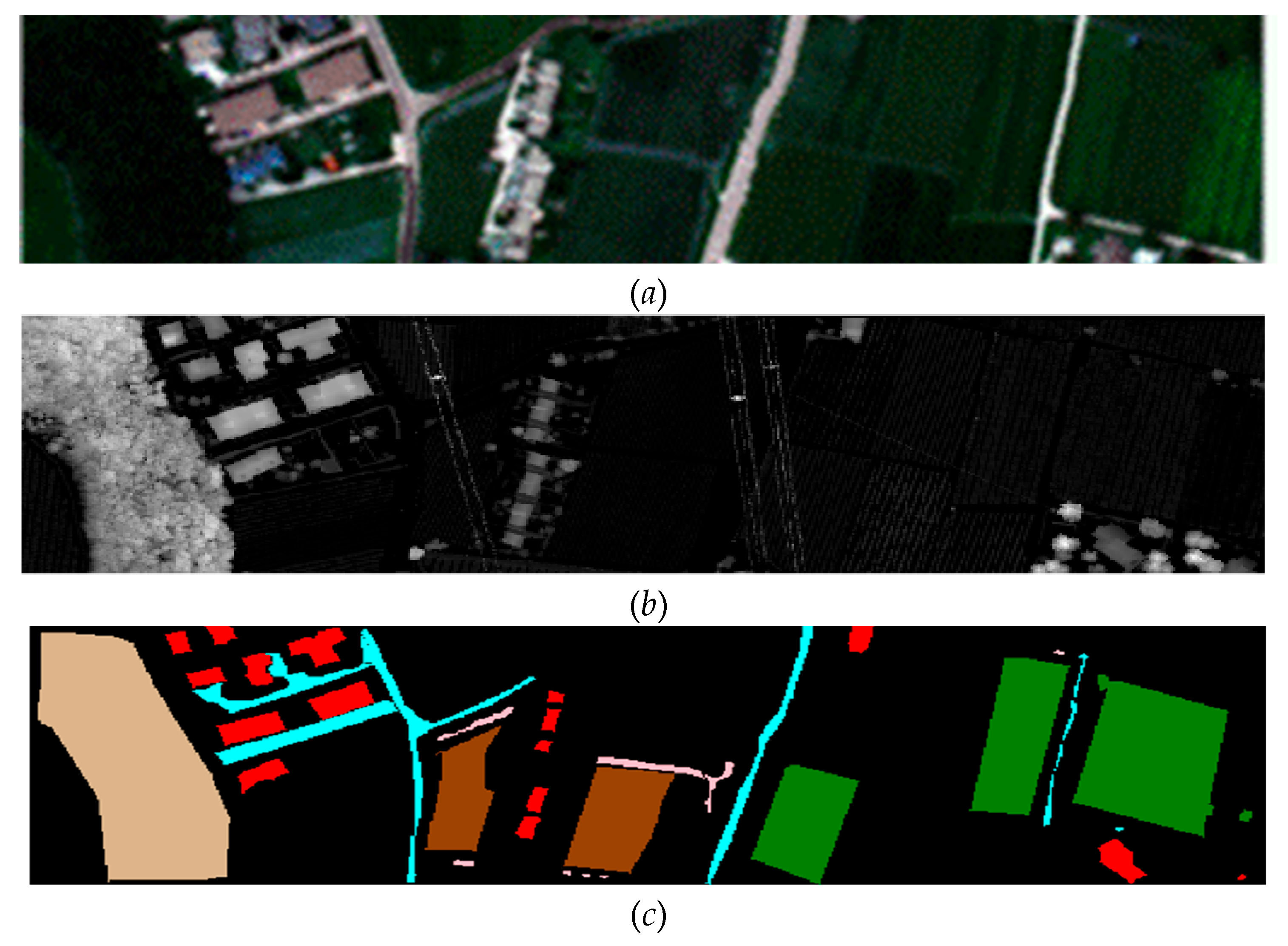
Figure 3.
(a) False-color image of the Houston 2013 HSI. (b) LiDAR DSM image (grayscale). (c) Ground truth land-cover map.
Figure 3.
(a) False-color image of the Houston 2013 HSI. (b) LiDAR DSM image (grayscale). (c) Ground truth land-cover map.

Figure 4.
Classification maps for the Trento obtained with different methods. (a) L-3DCNN(b) MDGCN(c) AMGCFN(d) MS-GWCN (e)MS-GWCT.
Figure 4.
Classification maps for the Trento obtained with different methods. (a) L-3DCNN(b) MDGCN(c) AMGCFN(d) MS-GWCN (e)MS-GWCT.
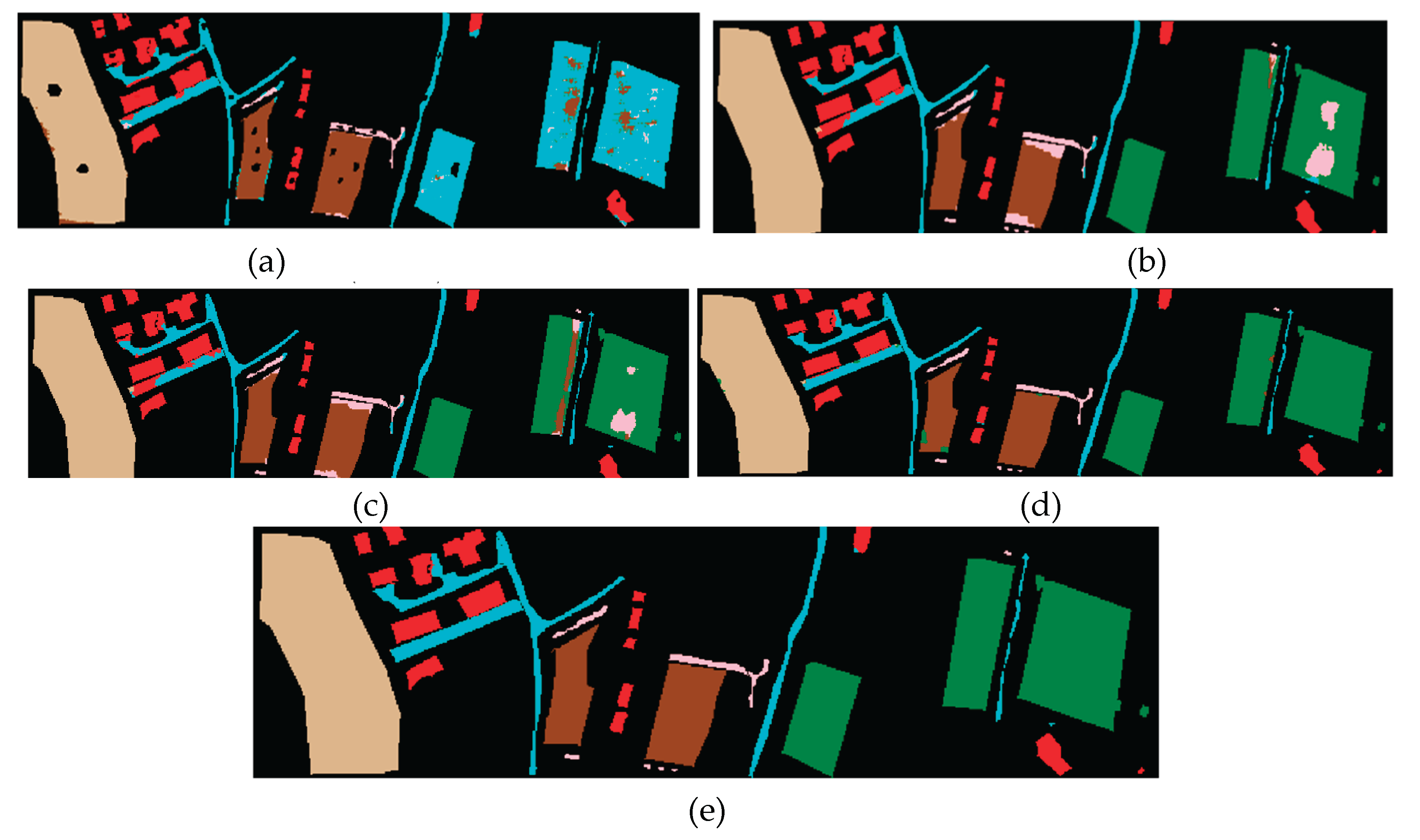
Figure 5.
Classification maps for the Houston 2013 were obtained with different methods. (a) L-3DCNN(b) MDGCN(c) AMGCFN(d) MS-GWCN (e)MS-GWCT.
Figure 5.
Classification maps for the Houston 2013 were obtained with different methods. (a) L-3DCNN(b) MDGCN(c) AMGCFN(d) MS-GWCN (e)MS-GWCT.
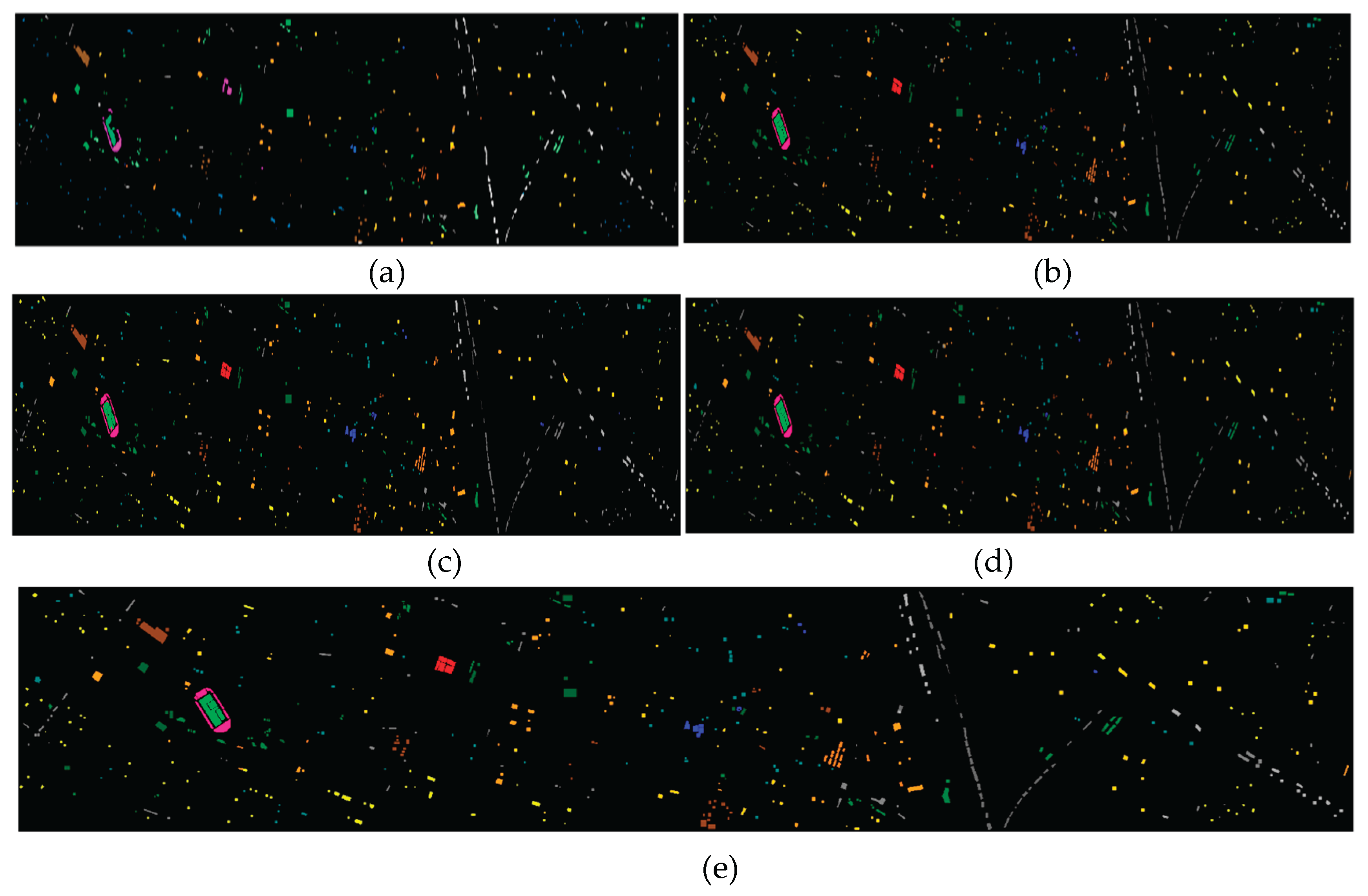
Table 1.
Hyperparameters selected by the Schrödinger Optimization Algorithm (SOA) for the MS-GWCT model on Houston 2013 and Trento. Best validation fitness is 0.5·OA + 0.5·AA.
Table 1.
Hyperparameters selected by the Schrödinger Optimization Algorithm (SOA) for the MS-GWCT model on Houston 2013 and Trento. Best validation fitness is 0.5·OA + 0.5·AA.
| Setting (best score = 0.5·OA + 0.5·AA) | Houston 2013 | Trento |
| Best validation score | 0.9839 | 1.0000 |
| lr | 0.00023871043249157518 | 0.00013906791054091116 |
| wd | 4.096561613265615e-05 | 2.0731719263694528e-05 |
| Scales(S) | 7 | 9 |
| Chebyshev order (K) | 6 | 7 |
| GWConv dropout (p_drop) | 0.18869587854491282 | 0.13767093915505982 |
| Graph drop_rate | 0.18729484147430908 | 0.1963433527455134 |
| Graph add_rate | 0.06889170537843169 | 0.1522279403980706 |
| Focal loss α (focal_alpha) | 0.6358869291955631 | 0.6716385831661724 |
| Label smoothing ε (smoothing) | 0.019552026308837303 | 0.006405681633777294 |
| LR warm-up fraction (warmup_frac) | 0.05187053248990214 | 0.11755789068433509 |
| num_classes | 15 | 6 |
| Transformer width (d_model) | 512 | 192 |
| Attention heads (n_heads) | 4 | 8 |
| Transformer layers (n_layers) | 3 | 3 |
| Attention dropout (attn_drop) | 0.14922111502378144 | 0.164552322654166 |
| FFN expansion (ff_mult) | 4 | 3 |
| FFN dropout (ff_drop) | 0.24005765846784655 | 0.16817161653543305 |
| Architecture (arch) | transformer | transformer |
| Feature temperature (τ_f) | 1.5718486792925597 | 2.0200865314348366 |
| Position temperature (τ_p) | 0.37361476863415904 | 0.07233603963646137 |
| lp_alpha | 0.7089477684144789 | 0.8310524687970329 |
| SupCon temperature (supcon_t) | 0.1 | 0.28949931973661946 |
| SupCon weight (supcon_w) | 0.19884437476947253 | 0.32742632202561217 |
Table 2.
Final MS-GWCT model settings for Trento and Houston 2013.
| Hyperparameter | Trento | Houston 2013 |
| Scales S | 8 | 10 |
| Polynomial order K | 6 | 6 |
| GWConv dropout | 0.30 | 0.30 |
| Graph augmentation (drop / add) | 0.10 / 0.05 | 0.12 / 0.08 |
| Loss | Focal loss (α=0.55, γ=1.5) | Focal loss (α=0.55, γ=1.5) |
| Label smoothing | 0.03 | 0.03 |
| Learning rate | 4.0×10⁻⁵ | 4.0×10⁻⁵ |
| Weight decay | 8.0×10⁻⁵ | 8.0×10⁻⁵ |
| Warmup | 10% of 400 epochs | 10% of 400 epochs |
| Max epochs | 400 | 400 |
| Final checkpoint | EMA of last-epoch weights | EMA of last-epoch weights |
| Seeds / runs | 5 independent runs | 5 independent runs |
| Test-Time Augmentation (TTA) | 12 forward passes | 12 forward passes |
Table 3.
Classification accuracy (%) on Trento and Houston 2013 for our MS-GWCT and baseline methods.
Table 3.
Classification accuracy (%) on Trento and Houston 2013 for our MS-GWCT and baseline methods.
| Classes | CLASSES-NAME | L-3DCNN | MDGCN | AMGCFN | MS-GWCN | MS-GWCT |
| 1 | Apple Trees | 98.02 ± 0.51 | 90.70± 0.07 | 91.30 ± 2.80 | 87.25±2.15 | 97.28±0.39 |
| 2 | Buildings | 100.00 ± 0.00 | 92.30± 0.14 | 99.85 ± 0.36 | 99.35±1.29 | 99.93±0.06 |
| 3 | Ground | 85.72 ± 3.54 | 97.30± 0.27 | 85.05 ± 6.45 | 84.68±8.25 | 99.63±0.70 |
| 4 | Woods | 100.00 ± 0.00 | 100± 0.00 | 100± 0.00 | 76.16±2.71 | 99.85±0.13 |
| 5 | Vineyard | 99.65 ± 0.18 | 37.7±2.65 | 92.80± 3.24 | 98.20±1.36 | 99.67±0.14 |
| 6 | Roads | 81.44 ± 1.42 | 65.66± 0.10 | 83.69±1.99 | 91.06±0.26 | 94.34±0.65 |
| OA(%) | 97.50 ± 0.11 | 72.94± 1.72 | 94.42±1.24 | 87.25±2.15 | 98.86±0.16 | |
| AA(%) | 94.14 ± 0.66 | 80.59± 1.74 | 92.11±0.83 | 93.03±0.95 | 98.44±0.17 | |
| κ(×100) | 96.66 ± 0.15 | 66.31±1.92 | 92.62±.61 | 85.49±2.42 | 98.47±0.21 | |
Table 4.
Accuracy (%) of the different methods on the Houston 2013 dataset.
| Classes | CLASSES-NAME | L-3DCNN | MDGCN | AMGCFN | MS-GWCN | MS-GWCT |
| 1 | Healthy grass | 82.89±1.10 | 87.89±1.10 | 75.98±1.85 | 82.08±0.70 | 85.75±2.93 |
| 2 | Stressed grass | 99.74±0.25 | 95.74±0.25 | 80.58±1.70 | 93.95±2.15 | 99.80±0.11 |
| 3 | Synthetic grass | 99.96±0.09 | 99.96±0.09 | 90.28±3.30 | 99.72±0.27 | 100.00±0.00 |
| 4 | Tree | 97.12±1.49 | 95.12±1.49 | 82.85±3.63 | 93.39±1.50 | 100.00±0.00 |
| 5 | Soil | 96.97±0.32 | 97.97±0.32 | 98.75±1.01 | 92.73±0.36 | 100.00±0.00 |
| 6 | Water | 96.08±0.63 | 93.08±0.63 | 94.87±1.89 | 99.44±0.26 | 95.80±0.00 |
| 7 | Residential | 95.04±1.28 | 90.04±1.28 | 63.33±2.88 | 95.50±1.07 | 85.26±7.38 |
| 8 | Commercial | 91.00±2.50 | 91.00±2.50 | 86.73±3.93 | 87.06±1.03 | 95.10±1.40 |
| 9 | Road | 86.29±2.49 | 88.29±2.49 | 80.13±3.66 | 86.18±1.33 | 91.12±1.55 |
| 10 | Highway | 64.50±8.94 | 74.50±8.94 | 81.60±3.12 | 84.16±6.84 | 71.93±0.15 |
| 11 | Railway | 85.46±2.78 | 85.46±2.78 | 99.85±0.25 | 91.04±6.05 | 98.03±2.62 |
| 12 | Parking lot 1 | 85.73±3.09 | 85.73±3.09 | 97.67±2.82 | 87.17±11.42 | 91.47±3.72 |
| 13 | Parking lot 2 | 89.96±2.16 | 89.96±2.16 | 69.50±3.93 | 91.07±0.29 | 86.39±4.12 |
| 14 | Tennis court | 100.00±0.00 | 100.00±0.00 | 98.72±2.62 | 100.00±0.00 | 100.00±0.00 |
| 15 | Running track | 100.00±0.00 | 100.00±0.00 | 94.70±5.59 | 99.38±0.04 | 100.00±0.00 |
| OA(%) | 89.81±0.78 | 89.81±0.78 | 85.36±0.36 | 90.99±0.41 | 92.60±0.61 | |
| AA(%) | 91.38±0.56 | 91.38±0.56 | 86.37±0.36 | 92.11±0.35 | 93.37±0.39 | |
| κ(×100) | 88.94±0.85 | 88.94±0.85 | 84.11±0.39 | 90.22±0.44 | 91.97±0.67 | |
Table 7.
Impact of Removing Coordinate Positional Encoding (no_pos=1 vs no_pos=0) on Houston: Per-Class Accuracies (%) and Overall Metrics (OA, AA, κ×100).
Table 7.
Impact of Removing Coordinate Positional Encoding (no_pos=1 vs no_pos=0) on Houston: Per-Class Accuracies (%) and Overall Metrics (OA, AA, κ×100).
| CLASSES-NAME | No Positional Encoding (no_pos=1) | No Positional Encoding (no_pos=0) |
| Healthy grass | 83.10 | 83.10 |
| Stressed grass | 100.00 | 100.00 |
| Synthetic grass | 100.00 | 100.00 |
| Tree | 100.00 | 100.00 |
| Soil | 100.00 | 100.00 |
| Water | 95.80 | 95.80 |
| Residential | 90.30 | 90.30 |
| Commercial | 95.73 | 95.73 |
| Road | 84.99 | 84.99 |
| Highway | 59.94 | 59.94 |
| Railway | 97.91 | 97.91 |
| Parking lot 1 | 79.73 | 79.73 |
| Parking lot 2 | 84.56 | 84.56 |
| Tennis court | 100.00 | 100.00 |
| Running track | 100.00 | 100.00 |
| OA(%) | 90.29 | 90.29 |
| AA(%) | 91.47 | 91.47 |
| κ(×100) | 89.46 | 89.46 |
Table 8.
Ablation of Loss Functions on the Houston 15-Class Dataset: Per-Class Accuracy (%) and Overall Metrics (OA, AA, κ×100).
Table 8.
Ablation of Loss Functions on the Houston 15-Class Dataset: Per-Class Accuracy (%) and Overall Metrics (OA, AA, κ×100).
| CLASSES-NAME | CE (no focal, no smoothing) |
CE + label smoothing | Focal only | Focal + smoothing | Focal + smoothing + contrastive |
| Healthy grass | 83.10 | 83.10 | 83.10 | 83.10 | 83.10 |
| Stressed grass | 97.56 | 97.65 | 97.65 | 97.65 | 99.72 |
| Synthetic grass | 100.00 | 100.00 | 100.00 | 100.00 | 100.00 |
| Tree | 100.00 | 100.00 | 100.00 | 100.00 | 100.00 |
| Soil | 100.00 | 100.00 | 100.00 | 100.00 | 100.00 |
| Water | 95.80 | 95.80 | 95.80 | 95.80 | 95.80 |
| Residential | 78.08 | 78.92 | 77.61 | 77.61 | 78.08 |
| Commercial | 97.34 | 96.20 | 93.45 | 96.30 | 98.29 |
| Road | 83.47 | 83.29 | 88.29 | 83.57 | 84.49 |
| Highway | 55.12 | 50.00 | 48.55 | 48.55 | 58.13 |
| Railway | 97.91 | 92.88 | 96.87 | 92.79 | 98.29 |
| Parking lot 1 | 82.23 | 82.42 | 81.27 | 82.23 | 83.47 |
| Parking lot 2 | 100.00 | 99.30 | 99.30 | 99.30 | 100.00 |
| Tennis court | 100.00 | 100.00 | 100.00 | 100.00 | 100.00 |
| Running track | 100.00 | 100.00 | 100.00 | 100.00 | 100.00 |
| OA(%) | 89.18 | 88.28 | 88.48 | 88.05 | 89.77 |
| AA(%) | 91.37 | 90.64 | 90.79 | 90.46 | 91.45 |
| κ(×100) | 88.25 | 87.27 | 87.49 | 87.02 | 90.81 |
Table 9.
Effect of Graph Augmentation and Test-Time Augmentation (TTA=16) on the Houston Dataset: Per-Class Accuracies (%) and Overall Metrics.
Table 9.
Effect of Graph Augmentation and Test-Time Augmentation (TTA=16) on the Houston Dataset: Per-Class Accuracies (%) and Overall Metrics.
| CLASSES-NAME | noGA_noTTA (GraphAug=OFF, TTA=0) |
GA_TTA (GraphAug=ON, TTA=16) |
| Healthy grass | 83.10 | 83.10 |
| Stressed grass | 100.00 | 100.00 |
| Synthetic grass | 100.00 | 100.00 |
| Tree | 100.00 | 100.00 |
| Soil | 100.00 | 100.00 |
| Water | 95.80 | 95.80 |
| Residential | 87.97 | 88.34 |
| Commercial | 95.73 | 95.86 |
| Road | 80.83 | 82.92 |
| Highway | 59.94 | 59.96 |
| Railway | 97.91 | 97.91 |
| Parking lot 1 | 80.02 | 79.76 |
| Parking lot 2 | 84.56 | 100.00 |
| Tennis court | 100.00 | 100.00 |
| Running track | 100.00 | 100.00 |
| OA(%) | 89.75 | 89.98 |
| AA(%) | 91.06 | 91.26 |
| κ(×100) | 88.87 | 90.01 |
Table 10.
Per-class Accuracy (%) under Manual vs. SOA Hyperparameter Tuning (GA=ON, TTA=16).
| CLASSES-NAME | MANUAL (GA=ON, TTA=16) |
SOA (GA=ON, TTA=16) |
| Healthy grass | 83.10 | 86.71 |
| Stressed grass | 100.00 | 99.25 |
| Synthetic grass | 100.00 | 100.00 |
| Tree | 100.00 | 100.00 |
| Soil | 100.00 | 100.00 |
| Water | 95.80 | 95.81 |
| Residential | 89.46 | 88.81 |
| Commercial | 95.73 | 95.73 |
| Road | 88.29 | 95.66 |
| Highway | 59.94 | 62.84 |
| Railway | 97.91 | 96.12 |
| Parking lot 1 | 79.64 | 85.88 |
| Parking lot 2 | 84.56 | 91.23 |
| Tennis court | 100.00 | 100.00 |
| Running track | 100.00 | 100.00 |
| OA(%) | 90.50 | 92.10 |
| AA(%) | 91.63 | 93.20 |
| κ(×100) | 88.68 | 91.43 |
Disclaimer/Publisher’s Note: The statements, opinions and data contained in all publications are solely those of the individual author(s) and contributor(s) and not of MDPI and/or the editor(s). MDPI and/or the editor(s) disclaim responsibility for any injury to people or property resulting from any ideas, methods, instructions or products referred to in the content. |
© 2025 by the authors. Licensee MDPI, Basel, Switzerland. This article is an open access article distributed under the terms and conditions of the Creative Commons Attribution (CC BY) license (http://creativecommons.org/licenses/by/4.0/).
Copyright: This open access article is published under a Creative Commons CC BY 4.0 license, which permit the free download, distribution, and reuse, provided that the author and preprint are cited in any reuse.


