Submitted:
13 October 2025
Posted:
13 October 2025
You are already at the latest version
Abstract
Strain-hardening cementitious composite (SHCC), also known as engineered cementitious composite (ECC), is a cementitious composite with high ductility, which shows strain-hardening behavior with saturated multiple cracking under direct tension. Sprayed SHCC is a type of SHCC sprayed at high speeds through a nozzle onto the surface of a substrate, which is widely used for structural reinforcement and repair applications. There are several review articles on SHCC for conventional cast applications; however, a comprehensive review and analysis of sprayed SHCC is lacking. To address this, this paper aims to compare the design principles and performance of cast and sprayed SHCC and to review the application and spraying processes of sprayed SHCC. This comprehensive review examines the theoretical foundations, material design principles, performance characteristics, and practical applications of sprayed SHCC. The mixture design theory is thoroughly analyzed, and the fundamental properties of sprayed SHCC are discussed, including pumpability, sprayability, and their evaluation methods. The review investigates the transition zone between substrate and sprayed SHCC overlay, interface failure modes, shear-slip behavior, and various influencing factors, with comparisons to conventional cast SHCC. Current applications of sprayed SHCC in infrastructure repair, strengthening, and durability control are discussed, demonstrating the practical viability and advantages of this technology. This state-of-the-art review is expected to offer valuable insights into further development and wider applications of sprayed SHCC in the construction industry.
Keywords:
sprayed SHCC
; mixture design
; spraying performance
; mechanical properties
; interfacial bonding performance
; applications
1. Introduction
To address the brittleness of concrete, fiber-reinforced cementitious composite (FRCC) was developed in the 1970s [1]. Strain-hardening cementitious composite (SHCC), also known as engineered cementitious composite (ECC), is a special type of FRCC that achieves ultimate tensile strains of 3%–8% and multiple micro-cracking characteristics by optimizing matrix composition, enhancing fiber performance, and improving the fiber-matrix interface. This far exceeds the 0.02% ultimate tensile strain of conventional concrete, with tensile ductility more than 300 times that of plain concrete [2, 3]. In the strain-hardening stage, the crack width of SHCC can be controlled below 100 μm. The compressive strength of conventional SHCC ranges from 30–80 MPa, while high-strength SHCC can exceed 100 MPa with tensile strains up to 11% [4].
Compared to cast SHCC, sprayed SHCC enables rapid construction through high-speed spraying and can be categorized as dry-mix or wet-mix depending on the material-adding sequence [5, 6]. This technology replaces steel mesh with fiber, significantly improving construction efficiency and expanding applications in structural repair, slope reinforcement, and other fields. Studies have shown that applying sprayed SHCC in masonry retrofitting can enhance the shear strength of composite structures by 4.5–7 times [7, 8] and limit maximum crack widths in beams to below 0.45 mm [9]. However, the spraying process causes fibers to orient parallel to the spraying direction with some loss before hitting the substrate surface, leading to lower fiber volume fractions compared to cast SHCC [10-12]. Additionally, sprayed SHCC requires a balance between low plastic viscosity (to reduce pumping friction) and high yield stress (to minimize rebound) to achieve the desired buildup thickness on the substrate surface [13, 14]. Current research focuses on improving sprayability through admixture incorporation and mixture optimization, with experiments showing optimal sprayability at a yield stress of 92–119 Pa and plastic viscosity of 4.9–7.2 Pa·s [14-17]. Like cast SHCC, sprayed SHCC also shows strain-hardening behavior, making it suitable for structural repair and strengthening, especially in tension or flexural components. However, the spraying process can significantly affect fiber distribution [18]. Moreover, the interfacial transition zone (ITZ) between the sprayed layer and substrate is often the weakest part due to high porosity [19]. The bond performance between sprayed SHCC and the substrate is affected by substrate roughness, surface moisture, curing methods, and overlay thickness [20]. Studies have shown that an overly dry substrate leads to significant shrinkage and cracking of the sprayed SHCC layer, so it is recommended that the single-layer spraying thickness not exceed 25 mm to prevent delamination [21]. Discrete crack models reveal that a 10 mm thick SHCC overlay can induce multiple cracks at the interface between the overlay and substrate, while a 30 mm thick overlay can increase wall shear strength by 4.65 times [22].
Although existing reviews have summarized the material design, durability, and multi-scale modeling of fiber pullout behavior in SHCC [23-27], limited research has focused on the relationship between flowability, fiber orientation, and the mechanical properties of sprayed SHCC. The conflict between pumpability and sprayability requires further resolution. This paper provides a comprehensive review of the design principles, key raw materials, and their influence on performance, as well as the fresh and hardened properties of sprayed SHCC, and comparison with cast SHCC. It aims to provide scientific and practical references for further research on sprayed SHCC and is expected to expand the applications of sprayed SHCC in the construction industry.
2. Mixture design theory of sprayed SHCC
Improper mixture design for sprayed SHCC with high fiber content may lead to high viscosity, poor fiber dispersion, high pumping resistance, insufficient build-up thickness, and further affect the mechanical properties and durability of sprayed SHCC. Therefore, a scientific mixture proportion design for sprayed SHCC should ensure the synergistic optimization of both its rheology during pumping and spraying processes and mechanical properties after hardening.
2.1. Mixture design based on micromechanical criteria
The mixture design of sprayed SHCC is based on the micromechanics of fiber bridging of microcracks and their propagation mode. The design basis of SHCC links the material microstructure to the composite tensile performance [28]. To satisfy the conditions for strain-hardening and multiple cracking characteristics, the size of initial matrix flaws, matrix toughness, and the displacement (σ–δ) behavior of crack-bridging fibers must conform to the energy and strength criteria as expressed in Eqs. (1) to (4), and as illustrated in Figure 1 [29, 30]. The σ–δ law describes the constitutive relationship between the tensile stress (σ) acting on the matrix crack plane and the crack opening displacement (δ) of a single crack, which emphasizes the synergistic interactions among the fiber, the matrix, and the fiber-matrix interface.
From the σ–δ curve in Figure 1, the maximum bridging stress can be inferred. According to the strength criterion, the steady-state matrix cracking stress must be lower than the maximum bridging capacity of fibers, as shown in Eq. (1). This requirement ensures that the tensile stress that initiates a steady-state crack from a pre-existing matrix flaw is below the fiber bridging capacity [30]. Otherwise, the fibers would rupture and/or pull out after matrix cracking, failing to serve their bridging function, and the composite would exhibit a strain-softening behavior. According to the energy criterion, Eqs. (2) to (4), the fracture toughness at the crack tip () must be lower than the maximum complementary energy of fibers (), a key condition for achieving steady-state crack extension rather than Griffith fracture [31, 32].
where represents the tensile cracking strength of the matrix (MPa); depends on the fracture toughness and defect size distribution of the matrix [28]; is the peak fiber bridging strength (MPa); is the crack tip toughness (); is the complementary energy (J/m2); and (mm) are the corresponding crack widths for stresses and , respectively; is the steady-state bridging stress (MPa); () and Ec (GPa) are matrix fracture toughness and Young’s Modulus, respectively.
In SHCC, achieving a steady-state crack enables the development of multiple cracks as the imposed tensile load increases and activates smaller flaws successively. When the applied tensile stress reaches , the composite exhausts the bridging capacity at one of the multiple crack sites, resulting in the localization of crack opening at decreasing bridging traction, i.e., tension softening.
From the above discussion, it can be seen that and should be minimized, and and should be maximized in the mixture design of SHCC to meet the energy and strength criteria. The pseudo-strain-hardening (PSH) index can be used to assess the strain-hardening potential of SHCC, which is defined in Eqs. (5) and (6) [30, 33]. A high PSH is preferred for steady-state crack propagation in the presence of material variability [34]. Li [2] and Kanda et al. [32] pointed out that while and represents theoretical prerequisites for multiple cracking of SHCC, experimental data suggest the need for and due to fiber and matrix parametric variability associated with composite processing.
As shown in Figure 2, the performance-driven design approach (PDDA) proposed by Li et al. [30, 35] connects the material structure and mechanical properties to achieve the high ductility of SHCC. By quantitatively analyzing critical microscopic parameters, such as matrix fracture toughness, fiber strength, and bond strength at the fiber-matrix interface, the corresponding microscopic mechanical models are used to predict macroscopic mechanical behaviors. This enables precise engineering control of SHCC, including ductility and cracking resistance. Specifically, the PDDA process first clarifies the performance requirements for structural applications and then optimizes the fiber-matrix interactions through interface engineering, leading to a scientific and systematic design methodology for SHCC materials.
It should be noted that the s(d) relation is influenced by fiber orientation as affected by the spray process. Similarly, the fiber/matrix interface properties and the matrix flaw size and toughness can be affected by the spray process. Thus, the tensile properties of spray SHCC can be highly dependent on the spray operation details, as will be discussed in Section 5.3.2.
2.2. Mixture design based on rheological properties of sprayed SHCC
2.2.1. Definition and requirements for the rheology of sprayed SHCC
The rheology of SHCC governs its deformation and flow resistance during pumping and spraying processes, primarily characterized by yield stress, plastic viscosity, and thixotropy [36]. For sprayed SHCC, low dynamic yield stress enables smooth flow through pipes and nozzles during pumping, while developing adequate plastic viscosity and cohesiveness after spraying ensures overlay stability and prevents sagging or segregation [13, 37] (see Section 5.1 and 5.2 for details). Additionally, ideal sprayed SHCC exhibits distinct thixotropic behavior, showing increased flowability under shear with rapid recovery to a cohesive state at rest, to enable rapid setting and achieve the desired build-up thickness that satisfies structural requirements [38]. Consequently, the design of sprayed SHCC involves carefully balancing yield stress, plastic viscosity, and thixotropy, as illustrated in Figure 3.
To achieve continuous and stable spraying as well as superior mechanical properties, the rheology of sprayed SHCC should meet the multi-stage requirements. Zhu et al. [39] detailed the specific rheological requirements for sprayed SHCC in the mixing, pumping, spraying, and build-up stage: (1) The mixing stage of sprayed SHCC should ensure the uniform distribution of fibers; (2) The pumping stage requires sprayed SHCC to exhibit high initial deformability and low viscosity to minimize frictional resistance within the conveying pipes; (3) The spraying stage requires high concrete adhesion and minimal rebound loss. Zhu et al. [39] proposed deformation index and atomization properties as assessment tools for rheological changes during spraying. Freshly sprayed SHCC requires excellent flowability and deformability during pipe transportation until it is sprayed onto the substrate (as shown in Figure 4). Upon spraying onto the substrate surface, its deformability rapidly decreases while cohesiveness increases, allowing the material to attain sufficient build-up thickness and meet structural performance requirements.
2.2.2. Rheology influence factors
Unlike ordinary shotcrete, sprayed SHCC contains a relatively high-volume fraction (typically 2% or less) of high aspect ratio polymer fibers that bridge cracks, transfer loads, and enhance ductility of the sprayed SHCC. The adjustment of sprayed SHCC rheology aims not only to facilitate pumping and spraying but also to ensure uniform fiber dispersion and to avoid excessive voids [40, 41]. The effect of polymer fibers on the rheological properties of the fresh mix depends on the stiffness, aspect ratio, and volume fraction of the fibers [42]. Polymer fibers have distinct mechanical properties with an elastic modulus of 10–100 GPa (compared to approximately 200 GPa for steel fibers) and elongations of 3%–15%, enabling substantial deformation under tension without fracture [43]. According to Forgacs and Mason [44], lower stiffness or higher aspect ratio promotes fiber bending. Unlike rigid fibers, which tend to align preferentially in the matrix under shear flow, flexible polymer fibers remain randomly oriented, bent, and twisted in SHCC even when subjected to shear fields during mixing, pumping, and spraying [45]. In regions of high shear within SHCC, flexible polymer fibers tend to align with the flow direction. When the SHCC shear force decreases, fibers partially revert to a bent state due to their inherent elasticity and resistance from the surrounding matrix, as shown in Figure 5. This reversible orientation change enhances SHCC thixotropy by restoring its internal structure after shear cessation. From a particle-packing perspective, flexible fibers occupy inter-particle voids, disrupting the original particle packing structure and forming fiber networks that restrict particle sliding and rearrangement, which directly increases yield stress. The rheological impact of fiber can be quantified by treating SHCC as a colloidal suspension system, where adding fibers increases the shear viscosity of the suspension [46, 47]. According to the Krieger-Dougherty model, when the effective volume fraction of flexible fibers with high aspect ratios approaches the critical value, the viscosity of the paste increases exponentially [48]. Consequently, polymer fibers with high aspect ratios and high-volume fractions lead to increased yield stress, elevated plastic viscosity, and enhanced thixotropy in sprayed SHCC.
The rheological properties of sprayed SHCC can be regulated by controlling the water-to-cement ratio, optimizing the cementitious material composition and aggregate gradation, incorporating admixtures, and optimizing the mixing process [49-52]. Ku et al. [51] found that a higher water-to-cement ratio might improve pumpability but adversely affect the sprayability. An alkali-free accelerator and organic polymer tackifier can be used to increase the yield stress and plastic viscosity of sprayed SHCC, thereby enhancing sprayability, reducing rebound rates, and minimizing material loss during spraying [53]. A homogeneous aggregate gradation following the Fuller curve or the modified Andreasen model can improve flowability without increasing the amount of water, simultaneously maintaining sufficient viscosity to prevent segregation [54]. Moreover, incorporating ultra-fine spherical particles, such as nano-silica, can effectively increase the yield stress and build-up thickness of sprayed SHCC [55].
2.2.3. Rheology-based mixture design
Evaluating and controlling rheological properties of cementitious materials, such as cement, mortar, fiber-reinforced concrete, and shotcrete, is challenging. In SHCC, the challenge is amplified by the large number of fibers. For SHCC reinforced with polypropylene (PP) fiber (PP-SHCC) and polyvinyl alcohol (PVA) fiber (PVA-SHCC) with aligned fibers, for 2% volume fraction of fibers with diameters of 40 μm and 17 μm, respectively, approximately 1600 and 8800 fibers will bridge across each square centimeter of crack surface [2]. The large number of fibers results in difficulties in pumping and spraying SHCC. Therefore, to satisfy both structural and performance requirements for sprayed SHCC, compatibility among raw materials in the mixture must be ensured. By integrating micromechanical principles with rheological control, Yang and Kim et al. [56, 57] applied the Integrated Structural and Materials Design (ISMD) concept, combining structural requirements with material properties. They selected appropriate matrices and fibers, adjusted the fiber-matrix interfacial properties, and optimized the paste rheology to ensure that the sprayed SHCC achieves desirable tensile strain-hardening behavior, multiple cracking characteristics, along with excellent pumpability, sprayability, and a low rebound rate.
Therefore, a systematic application of the rheological properties is required for mixture design to ensure that sprayed SHCC exhibits excellent construction performance (such as pumpability, sprayability, and build-up ability) and achieves the target structural properties. This design method is based on optimizing and controlling rheological parameters (e.g., yield stress, plastic viscosity, and thixotropy). It explicitly integrates the specific requirements of each spraying stage (mixing, pumping, spraying, and build-up), while simultaneously considering micromechanical criteria to ensure hardened sprayed SHCC has strain-hardening and multiple cracking behaviors, as illustrated in Figure 6.
3. Raw materials of sprayed SHCC
3.1. Matrix
3.1.1. Cementitious materials
Binder selection and dosage must ensure compatibility with chemical admixtures, sufficient pumpability, rapid early strength, and long-term durability for sprayed SHCC. In general, CEM I and CEM II Portland cement are often used in sprayed SHCC. CEM I 52.5R cement is the preferred choice for applications demanding high early strength, while CEM II/A-L 42.5R is recommended for typical strength requirements in sprayed SHCC [58]. Compared with ordinary Portland cement (OPC), rapid-hardening calcium sulfoaluminate (CSA) cement primarily consists of calcium sulfoaluminate (C₄A₃S̄) as the main mineral phase, supplemented by calcium sulfate and calcium sources. At early hydration stages, rapid reaction between calcium sulfoaluminate and calcium sulfate forms abundant needle-like ettringite crystals. It creates a dense network structure, providing significant strength within 1–3 hours, making CSA cement widely used in tunnel construction or slope support processes where shotcrete reinforcement is required [59]. Silica fume, an ultra-fine pozzolanic admixture (particle size is about 0.1–0.3 μm), increases matrix density through filling effects and pozzolanic reactions. Its spherical shape improves the rheological properties and fiber-matrix bonding of sprayed SHCC. However, a large amount of silica fume significantly increases paste viscosity and thixotropy, raising pumping and spraying resistance, and elevating the risks of autogenous shrinkage and cracking in sprayed SHCC [60]. To mitigate these effects, industry standards typically recommend silica fume additions not exceeding 12%–15% of cement weight, and Spanish standards specifically recommend keeping silica fume dosage below 10% by cement weight [61]. Choi et al. [62] demonstrated that incorporating 4.5% silica fume significantly enhances the compressive and flexural strengths of sprayed SHCC after spraying. Similarly, fly ash, with its spherical particle morphology, effectively improves the flowability and pumpability of sprayed SHCC. However, high fly ash content may reduce fiber-matrix interfacial bond strength, weakening the overall performance of sprayed SHCC. Kim et al. [57] found that fly ash content within 30% in sprayed SHCC balances workability and strength. Cabrera and Wooley [63] observed a noticeable reduction in rebound rate when 30% fly ash was incorporated. Therefore, carefully optimizing the proportions of cement, silica fume, and fly ash allows effective control of the rheological properties, setting time, strength development, and strain-hardening characteristics of sprayed SHCC.
3.1.2. Aggregates
According to micromechanical design principles and steady-state cracking requirements, the proportion of aggregates in SHCC is significantly lower than in plain concrete. Typically, fine aggregates (i.e., sands) are preferred over coarse aggregates because their smaller size creates more uniform stress distribution and reduces the fracture toughness of matrix, promoting the multiple cracking behavior essential for the strain-hardening performance of SHCC [64]. The effect of aggregate on the SHCC ductility is reflected in two aspects. Firstly, smaller aggregates reduce the matrix toughness [65] (Km), lowers the first-cracking strength of SHCC and facilitates the early transfer of loads to the fibers. Second, aggregate affects the distribution of fibers and interfacial properties, consequently influencing the supplementary energy and the fiber bridging strength. Previous studies indicate that specific aggregates, such as granite fines, can improve tensile strength by increasing particle friction [66], while river sand, by introducing effective defects, promotes crack formation [67]. Additional defects in SHCC from lower-strength fine aggregates reduce matrix fracture toughness and enhance strain-hardening potential, but their overuse hinders saturated multiple cracking [2, 67, 68]. As the proportion of fine aggregate increases, the tensile strength of the SHCC matrix initially increases and then decreases, while the compressive strength and the average crack width of the SHCC matrix decrease gradually. Thus, SHCC can be produced with acceptable ductility by suitably restricting the quantity of fine aggregate in the SHCC matrix and ensuring adequate bonding at the fiber-matrix interface.
The tensile strain capacity of SHCC is influenced by the distribution of pre-existing flaw sizes, matrix fracture toughness, and the fiber bridging strength, as shown in Figure 7. Uneven fiber dispersion reduces fiber bridging strength, enlarges critical flaw sizes, and activates fewer pre-existing flaws, which decreases the tensile strain capacity of SHCC [69]. In general, introducing coarse aggregates with larger particle sizes increases the number and size of internal defects, and increases matrix fracture toughness due to more tortuous crack propagation paths along interfacial transition zones (ITZ), thereby suppressing multiple cracking [70]. The flaws when using the coarse aggregate also cause variability in the cracking strength of the matrix between neighboring parallel cracks in the SHCC matrix. As existing cracks reach a critical opening under tensile stress, new cracks initiate at other flaw sites throughout the matrix, contributing to the desired multiple cracking behavior [70]. Xu et al. [71] demonstrated that increasing the particle size of the aggregate increases the total flaw size in the SHCC matrix. However, the probability density of smaller flaws (0.1–0.2 mm) decreases. The initial flaw size distribution in the SHCC can be quantified using a Weibull-type function, as expressed in Eq. (7) [68], where F(r) is the cumulative probability of an initial flaw with an equivalent radius less than r; k and λ are the shape and scale parameters, respectively; and is the minimum flow radius (mm).
According to the particle close-packing theory, continuously graded aggregates contribute to the increased density and dimensional stability of SHCC, enhancing the bonding between fibers and the matrix. The tensile properties of SHCC decrease with increasing aggregate particle size because the larger the aggregate particle size, the smaller the number of particles for the same aggregate amount. Hence, the lack of sufficiently distributed aggregate in the matrix results in a significant deviation in matrix fracture toughness and a gradual decrease in fiber bridging strength [70, 72]. To determine the optimal range of particle size of aggregate in SHCC, Lei et al. [73] assumed that 2 vol.% of the fibers in SHCC were uniformly distributed, forming an equidistant three-dimensional cubic lattice structure. The fiber space theory proposed by Romualdi assumed that continuous fibers are evenly distributed along the pullout direction [74]. Based on the above theory, Hu et al. [75] modified the equidistant three-dimensional cubic space with a uniform distribution of fibers by reducing the spacing between fibers and aggregate to 100 μm. This modification aimed to increase the spatial interlocking effect of fibers and aggregate, and the ideal average value of aggregate particle size was calculated using Eqs. (8) to (10).
where X is the dimension of the equidistant three-dimensional cubic lattice structure proposed by Lei et al. [73]; R is the fiber diameter (mm), and L is the total length of 2 vol.% fibers per unit cubic meter.
During the construction process of sprayed SHCC, aggregate size directly affects rebound behavior and pumpability. Studies have shown that maximum aggregate size positively correlates with rebound rate, with aggregates larger than 5 mm more likely to rebound during high-speed spraying [76]. Austin et al. [77] observed that each 1 mm increase in particle size can raise the rebound rate by roughly 2%–5%, particularly on vertical surfaces and overhead applications. To ensure pumping stability, Morgan [78] recommends that the maximum aggregate size should not exceed one-third of the delivery pipe diameter, typically kept within the 2–4 mm range. Furthermore, continuously graded aggregates demonstrate lower rebound rates and enhanced cohesiveness compared to uniformly sized aggregates. Moreover, according to CNR DT 204/2006 guidelines [79], to prevent aggregates from interfering with fiber distribution and orientation, the average aggregate size should not exceed one-quarter to one-third of the fiber length. Therefore, for sprayed SHCC, it is advisable to select fine aggregates with a maximum particle size of less than 4 mm, clean surfaces, regular shape, and continuous gradation to optimize spraying performance and strain-hardening behavior [78, 79].
3.2. Fiber
Commonly used fibers, such as PVA, PP, and polyethylene (PE), play a dual role in the design of sprayed SHCC. From the micromechanical perspective, these fibers enable strain-hardening and multiple cracking mechanisms by providing bridging forces across crack surfaces, with performance dependent on complex fiber-matrix interactions, including chemical bonding, frictional slip, and energy dissipation. Rheologically, fibers act as flexible units participating in paste flow, undergoing orientation changes and bending deformation under different shear conditions, forming network structures that affect particle packing, significantly affecting material yield stress, plastic viscosity, and thixotropy. To achieve tensile strain capacities of 3%–7%, SHCCs typically incorporate equal to or less than 2 vol.% PVA, PE, or high tenacity polypropylene (HTPP) fibers [24, 39]. Based on fiber bridging theory, fibers prevent structures from strain softening and brittle fracture, but a fiber-reinforced composite with PVA fiber content less than 2 vol.% may not exhibit saturated multiple cracking characteristics [80]. Additionally, fiber length (L) and diameter (d) determine fiber bridging strength and complementary energy . Yu et al. [81] demonstrated that a higher aspect ratio (L/d) increases fracture energy consumption during pull-out and reduces crack spacing. This is because a higher aspect ratio increases effective bonding area at crack interfaces, and fiber bridging efficiency directly correlates to embedment length, which is longer fibers providing a larger stress-transferring area within the matrix [82, 83]. Finer fibers imply a larger number of fibers due to their smaller cross-sectional area for a given volume fraction, creating more crack-bridging points that distribute applied loads more uniformly across the matrix and reduce the stress concentration, thereby minimizing local matrix crack formation [2].
Based on the research of Zhang et al. [34], micromechanical framework provides effective criteria for fiber selection in SHCC, and optimal fibers should possess the following characteristics: (1) Moderate aspect ratio to maintain composite flowability and fiber dispersion; (2) Appropriate elastic modulus to facilitate controlled microcracking under load; (3) Sufficient elongation at break to prevent breakage during mixing; (4) Balanced interfacial bond properties-neither too weak nor too strong. These criteria specify that fiber content should not be greater than 2 vol.%, with fiber lengths ranging from 6–12 mm, an elastic modulus greater than 10 GPa, tensile strain capacity above 3%, and excellent corrosion resistance and chemical stability within cementitious environments.
As previously mentioned, fiber dimensions and type influence the rheological properties of SHCC, thereby affecting fiber distribution. Uneven fiber distribution increases critical flaw size and introduces air voids, resulting in reduced tensile strain capacity, as only a small percentage of flaws are activated to form saturated cracks [69, 84]. Zhang and Li et al. [69, 84] suggested that increasing matrix plastic viscosity from 1–26 Pa·s raised the fiber dispersion coefficient from 0.43–0.85, as shown in Figure 8. However, excessive viscosity increases air entrapment, weakening interfacial bonding [69]. Swamy et al. [85] indicated that an optimal critical fiber volume and plastic viscosity exist for fiber-reinforced concrete, where an increase in aspect ratio permits reduced fiber contents. In conclusion, effective sprayed SHCC design requires integrated fiber parameter selection encompassing type, geometric parameters, and dosage to optimize dispersion uniformity, crack bridging efficiency, and processing workability.
3.3. Fiber-matrix interface
The fiber-matrix interface governs stress transfer and crack control in SHCC, and its performance can be effectively characterized through the fiber pullout process. Fiber pullout mechanics involve the following three sequential stages governed by interfacial bonding and friction mechanisms [86, 87]. (1) As load increases linearly to the critical shear strength Pc (OA segment), the fiber-matrix interface begins debonding from the fiber embedment end, forming a debonded length (Ld). When Ld equals the fiber embedment length (Le), the load-displacement curve reaches the initial peak Pa (AB segment). Assuming uniform stress distribution at this instant, the interfacial bond strength can be calculated from Eq. (11). (2) The fibers are fully debonded without slippage, and fiber displacement change is only contributed by the elastic stretch and free length of the debonded fiber segments, with the load gradually decreasing to Pb (BC segment). The corresponding chemical debonding energy (Gd) between fiber and matrix is calculated from Eq. (12). (3) Following complete debonding, fibers enter the slip phase with the following three possible modes based on the interfacial friction coefficient (β). (a) slip-hardening (β > 0) results from interfacial wear debris accumulation increasing contact area and resistance, potentially inducing fiber rupture, especially in PVA fiber systems [88]. (b) constant frictional sliding (β = 0) (CD segment) occurs when fiber and interface wear are minimal and interfacial friction remains stable during slippage; the fiber pullout load exhibits a negative linear relationship with displacement. (c) slip-softening (β < 0) develops through progressive contact area reduction and debris elimination during continued sliding. The whole process is illustrated in Figure 9.
where is the frictional bond strength (MPa); Pa is the maximum tensile force (N); df and Ld are the fiber diameter and fiber embedment length (mm), respectively; Gd is the chemical bond energy (J/m2); and Ef is the Young’s modulus of the fiber.
In sprayed SHCC, fiber surface characteristics are crucial to interfacial performance. PVA fibers, rich in hydroxyl groups, can chemically bond with Ca²⁺ ions released during cement hydration and form strong hydrogen bonds with C-S-H gel and Ca(OH)₂ crystals. This promotes dense deposition of hydration products and pronounced hydrophilicity [86, 89], significantly increasing chemical bond strength and frictional resistance. As a result, PVA fibers are more likely to rupture under load rather than gradually pull out. The typical polymer structure of commercial PVA fibers and their SEM appearance in the matrix are shown in Figure 10. In contrast, PE fibers lack hydroxyl groups, exhibit hydrophobicity, and primarily form mechanical interlocking and frictional contact with cement hydration products, with weak interfacial bond strength that is conducive to the fiber pull-out process. Accordingly, sprayed SHCCs prefer high-strength, high-modulus PE fibers over untreated PVA fibers [80]. Nevertheless, the hydroxyl functional groups abundant on PVA fiber surfaces enhance wetting within the matrix and enhance the dispersion of the fibers, which represents a significant advantage over PE fibers [90].
In sprayed SHCC systems, highly hydrophilic PVA fibers may form stronger interfacial bonds with the matrix during the spraying process compared to cast SHCC. Meanwhile, PE fibers with hydrophobic surfaces require surface functional group improvements to achieve uniform dispersion. Based on the existing studies, the methods for modifying PVA and PE fibers include a variety of techniques ranging from traditional oil coating to advanced plasma treatment and nanomaterial composite modification, as shown in Table 1.
3.4. Accelerator
The use of an accelerator in sprayed SHCC can significantly shorten the initial and final setting time and increase the compressive strength in 1–3 hours by accelerating the rapid formation of hydration products such as ettringite, thereby meeting structural reinforcement requirements. Based on alkali content, accelerators are classified as alkali or alkali-free types. Alkali accelerators typically contain aluminates, silicates, carbonates, and hydroxides [102]. Considering that alkali accelerators may trigger the alkali-aggregate reaction, which can weaken the long-term strength and durability of sprayed SHCC, alkali accelerators are generally added at a level of less than 10% of the cementitious material content [103]. Alkali-free accelerators maintain minimal alkali metal content (sodium and potassium), generally less than 1%, with aluminum salts and alkalis being the main active components. Standard alkali-free accelerators are typically combinations of aluminum hydroxide-based accelerators (Al(OH)₃) with aluminum sulfate (Al₂(SO₄)₃) or mixtures of calcium sulfoaluminate (C₄A₃S) and aluminates of sulfate (e.g., Al₂(SO₄)₃) [104].
Accelerator mechanisms on cement hydration encompass physical and chemical effects. Physical acceleration is based on the seed effect through calcium silicate hydrate (C-S-H) gel addition during the cement hydration process [105]. This method is widely used in commercial accelerators. The underlying principle is that C-S-H gel facilitates ion diffusion due to its porous nature and high specific surface area. This formation of C-S-H gel interconnects the cement particles in suspension, forming a 3D network, which reduces the cement setting time [106]. Chemical acceleration of cement hydration is mainly through the following three aspects to promote cement hydration: (1) Providing specific ions such as aluminum (Al³⁺) ion, calcium (Ca²⁺) ion, etc. that participate in hydration reactions without significantly altering solution alkalinity; (2) Increasing the pH value of the paste to disrupt cement mineral passivation layers and accelerate ion dissolution; (3) Forming metal complexes that modify hydration kinetics, altering hydration product crystalline morphology and growth rates.
Alkali-free accelerator mechanisms depend fundamentally on ionic chemistry and nucleation pathways. In aluminate-containing systems, aluminum sulfate (Al₂(SO₄)₃) reacts with Ca²⁺ ions released during the induction period of cement hydration to form Al(OH)₃ and ettringite [107, 108], increasing solid-liquid ratios and accelerating matrix hardening, as illustrated in Figure 11(a) [109]. Additionally, ettringite adsorbs onto the surface of clinker particles, enhancing their cohesion and further speeding up the initial and final setting times [108]. Soluble inorganic salts such as calcium chloride (CaCl₂) can also catalyze C-S-H gel generation [110, 111], but the resulting chloride ions promote steel corrosion and reduce the long-term durability of reinforced concrete. Other alkaline accelerators, including carbonates and nitrates, accelerate cement hydration by increasing Ca²⁺ concentration, though with weaker effects due to sulfate depletion and limited ettringite formation [112]. Other alkaline accelerators, such as sodium hydroxide (NaOH) and sodium silicate, provide Na⁺ and hydroxide ions (OH⁻), significantly increasing the alkalinity of the cement paste pore solution and consequently accelerating the early dissolution of C₃S [113]. In alkaline solutions, AlO₂⁻ ions convert to [Al(OH)₄]⁻, which subsequently reacts with Ca²⁺ and sulfate ions (SO₄²⁻) to produce AFt, AFm, and C-A-H phases, as illustrated in Eqs. (13) to (17) and Figure 11(b) [102].
The early-phase hydration products and heat evolution of cement with different accelerators are shown in Figure 12 [114]. In the sodium-aluminate system, the sharp increase in pH rapidly breaks down the passive film on cement mineral surfaces while supplying [Al(OH)₄]⁻ complexes, significantly shortening the hydration induction period to less than 1 hour and advancing the occurrence of the heat peak. The aluminum-sulfate accelerator promotes rapid nucleation of ettringite through the synergistic effect of externally provided SO₄²⁻ and Al³⁺ ions, resulting in a slightly delayed but higher peak of heat evolution.
In addition to the common liquid and powdered accelerators, cement-based accelerators, such as quick-setting cement, can be used to reduce the setting time of sprayed SHCC. Examples include calcium sulfoaluminate (CSA) cement and calcium aluminate cement (CAC). According to previous experiments, considering the cost and the long-term strength of sprayed SHCC, the typical dosage of quick-setting cement is usually kept at less than 10% of the cement weight [115-117]. Accelerators promote rapid C-S-H gel formation, providing nucleation sites for cement hydration while enhancing particle flocculation through bridging effects, which increases freshly-sprayed SHCC yield stress and buildup thickness [118]. However, since the accelerators alter the degree of cement hydration as well as the morphology and distribution of hydration products, Martinez-Ramirez et al. [119] found that the porosity of cement pastes containing alkaline accelerators was higher than that of cement pastes without accelerators after 28 days of curing. Increased fine pore volumes and higher porosity generally lead to more pronounced drying shrinkage in cement-based materials. Therefore, careful control of accelerator dosage is essential to mitigate potential adverse effects.
4. The spraying process of sprayed SHCC
Cast SHCC and sprayed SHCC differ significantly in their production processes. In sprayed SHCC, the material is conveyed through pneumatic devices and pumping systems to hoses and spray guns, where it is applied at high speed using an airflow of approximately 0.1–0.3 m3/min and air pressure of 200–600 kPa, with a typical spraying distance of 0.2–0.5 m from the substrate [9].
The spraying process can be categorized into dry and wet methods, depending on when water is added and the mixing duration. In dry spraying, dry materials are pneumatically conveyed, and water is introduced at the nozzle, making the mixing quality heavily dependent on operator skill. Wet spraying involves pre-mixing water with dry particles before pumping, producing rapid setting and adequate early strength [5, 6]. Since water is added at the gun outlet during dry spraying, the degree of mixing and homogeneity of the components in the shotcrete during spraying is substantially lower than in wet spraying [120]. Insufficient air pressure or air volume during the spraying process can reduce spraying speed and quality. Before spraying, the substrate surface should be cleaned to remove contaminants and moistened to minimize over-drying of the substrate and reduce water absorption from the sprayed SHCC. The sprayed SHCC is then pumped through hoses to the spray gun, applied to the substrate, and subsequently smoothed to achieve the desired finish [121]. The dry and wet mix shotcrete processes are shown in Figure 13.
To avoid fiber clogging or pumping difficulties during spraying, some fibers, such as glass fibers, can be cut to the required length using a chopper at the gun nozzle [122]. The chopped fibers are then sprayed onto the substrate surface in conjunction with mortar directly from the gun, rather than pre-mixing during initial preparation, as shown in Figure 14. Al-Ameen et al. [123] used two separate spray guns to introduce fiber addition separately at the head of the spray system. However, their results indicated that human error was inevitable in synchronizing and moving the spray paths, resulting in non-uniform fiber distribution within the matrix. Consequently, a single concentric spray system, which allows fibers and mortar to be sprayed simultaneously, is recommended to achieve more consistent fiber dispersion.
During the construction and maintenance of SHCC, the spraying processes can be selected according to the size of the construction area. Narrow-stream spraying is commonly employed for small construction areas, while fog spraying is preferred for large areas. Huang et al. [9] reported that narrow streams of sprayed SHCC can be observed at an airflow of about 0.3 m3/min and air pressure of 200 kPa, whereas fog sprays form at 0.1 m3/min airflow and 600 kPa air pressure, as shown in Figure 15. Lukkarila et al. [124] suggested that low-speed spraying should be preferred over high-speed spraying for SHCC. It should also be noted that the size distribution of flaws in SHCC can affect its multiple-cracking and tensile strain capacity, although the pneumatic pressure applied during spraying makes flaw size prediction in sprayed SHCC challenging.
Spraying direction also influences the overlay quality. When SHCC is sprayed vertically downward, the combined effects of air pressure and gravity result in a denser overlay on the substrate surface, especially near the interface between the substrate and the overlay. In contrast, overhead spraying creates more pores and interfacial cracks before the overlay hardens [125]. Due to rebound and potential detachment during the spraying process, the recommended maximum single-layer thickness is 50 mm for vertical spraying and 30 mm for overhead spraying [9]. Excessive thickness in overhead spraying can lead to immediate spalling or even delamination due to the effects of gravity. When the thickness of the overlay exceeds the maximum thickness of sprayed SHCC in a single continuous spraying, a layered spraying method should be adopted. Xu et al. [125] reported that 50 mm overhead overlays can be achieved in two 25 mm layers with a 3-hour interval. Lin et al. [126] successfully applied 30 mm-thick sprayed SHCC over the wall surface in three separate shots of 10 mm each at 45-minute intervals. Xu et al. [127] found that increasing the thickness of sprayed SHCC from 10–30 mm improved the ultimate load capacity of the structure by over 30%.
Since there are no standardized thickness and viscosity requirements for sprayed SHCC in substrate covering and reinforcement, mixture design and process parameters are often optimized through iterative experimental adjustments to achieve strong adhesion while minimizing material loss. Before spraying, the proportions of each constituent should be carefully adjusted to prevent hose clogging and reduce waste.
5. Properties of sprayed SHCC
To achieve a consistent overlay of the substrate surface and form a reliable reinforcement or repair layer, it is essential for sprayed SHCC to have excellent flowability and cohesion. This prevents clogging during pumping, ensures strong adhesion to the substrate, reduces sagging, and results in a low rebound rate. For sprayed SHCC, whether using dry spraying or wet spraying, the main goal for sprayed SHCC is to improve pumpability and sprayability, thereby enhancing the mechanical properties and durability of the substrate.
5.1. Pumpability
5.1.1. Pumpability mechanisms and material migration in sprayed SHCC
The pumpability of shotcrete refers to its ability to flow under pressure within a pumping system while maintaining its initial characteristics, emphasizing both flowability and stability [128]. Good pumpability requires shotcrete to have excellent flowability and stability, pass easily through pipes, and maintain stability without segregation under shear and pressure. Most of the existing studies on pumpability focus on the flow rate of shotcrete in the hose, the diameter of the hose, the pumping distance, the lubrication layer formed on the inner wall of the pipe, rheological properties, and slump [15-17]. The pumping pressure depends on the interfacial friction between the shotcrete and the pipe wall, which is determined by the thickness of the lubrication layer formed inside the pipe wall and the rheological properties, including yield stress, plastic viscosity, and thixotropy. The formula for the pumping pressure inside a shotcrete pipe is shown in Eq. (18) [129], where P is the pumping pressure (bar); L is the length of the pumping pipe (m), and R is the radius of the pipe (m); Q is the pumping flow rate of the shotcrete in the pipe (m3/h); is the filling factor that depends on the type of pump (0.7 for automatic pumps, 0.8 for stationary pumps); is the viscous constant (); is the yield stress at the interface of the lubrication layer on the pipe wall (Pa).
The flow behavior of freshly sprayed SHCC in the pipeline during pumping is complex. As shotcrete is transported from the pipe to the nozzle, segregation between aggregates and paste can occur, resulting from the migration of aggregates from high-shear zones to low-shear zones as shear forces decrease gradually from the pipe wall to zero at the center of the pipe. Coarse particles tend to move toward the center of the pipe due to the wall effect, while finer particles form a lubrication layer around the pipe. This lubrication layer reduces friction and fills gaps between particles, as shown in Figure 16 and Figure 17 [130, 131]. According to the principles and hypotheses proposed by Chapdelaine et al. [132], a lubrication layer approximately 1 mm thick around the hose forms at the start of pumping. Considering the rheological properties of concrete, pumping sprayed SHCC without a lubrication layer, typically 1–5 mm thick, is generally not feasible [133].
In addition to the radial separation of aggregate and paste, fibers also experience significant shear-induced migration and orientation evolution during pumping. Their morphological changes directly affect the rheological properties and shear effects of sprayed SHCC. Polymer fibers commonly used in sprayed SHCC, which generally have low stiffness, are more prone to bending and even entangling with each other during concrete pumping, easily forming fiber bundles and orienting along the flow direction. Under continuous shear, coarse particles and long fibers migrate radially, resulting in fiber enrichment in the pipe center and the formation of a fiber-depleted, paste-rich lubrication layer near the pipe wall [134]. Therefore, a fiber-aggregate ratio imbalance develops within the 1–5 mm lubrication layer adjacent to the wall. When the pumped material passes through sections with changes in pipe diameter, such as nozzles, fiber orientation redistributes, and transient bending or mechanical interlocking can occur, potentially leading to nozzle blockage. Switzer et al. [135] simulated frictional interactions between fibers and analyzed the influence of fiber stiffness on the rheological properties of the suspension, showing that suspension viscosity decreases with increasing fiber flexibility. Pu et al. [136] concluded that flexible polymer fibers enhance the non-Newtonian effect of concrete and promote particle agglomeration, resulting in plug flow formation. As shear rates increase during pumping, the interfacial shear can exceed the yield stress of the sprayed SHCC, causing the elastic flocculation structure formed by fibers and paste to break down, resulting in shear thinning [137].
5.1.2. Evaluation of pumpability
The slump test is traditionally used to evaluate the flowability of fresh shotcrete; however, it does not adequately reflect the stability of the sprayed SHCC. Consequently, freshly sprayed SHCC with a good slump does not necessarily meet pumpability requirements [138]. To more accurately assess pumpability, rheological tests are typically conducted to determine the yield stress and plastic viscosity of the material [128], and the pressure loss gradient and piston pressure (kPa/m) are measured during the pumping process [38, 131]. The Bingham model is commonly employed to characterize the rheological behavior of fresh concrete, emphasizing that the concrete must overcome the yield stress to initiate flow [128]. Yun et al. [38, 139] used an IBB rheometer to show that moderate silica fume content can reduce torque viscosity and piston pressure, thereby improving pumpability, whereas fly ash and steel fibers have adverse effects. During sprayed SHCC pumping in the pipe, from the initial low-speed flow stage to the stage where interfacial shear forces exceed the yield stress of sprayed SHCC, the lubricating layer on the inner pipe wall becomes the primary factor influencing pressure loss [131]. Pumping pressure loss depends on the pipe and lubrication length, rather than the initially applied pressure [140], and is not influenced by the lubrication layer thickness [141]. Liu et al. [6] confirmed a near-linear positive correlation between plastic viscosity and pumping pressure loss in tests with 25 shotcrete mixes in a 100 m delivery pipe.
Pumpability of sprayed SHCC can be significantly improved by systematically regulating the material composition and construction parameters. For material optimization, sprayed SHCC suspension stability can be enhanced by optimizing the particle size distribution and proportions of silica fume and fly ash, using accelerators to effectively adjust the setting time and rheological properties of freshly sprayed SHCC [142]. Air-entraining agents can be added to introduce micro-bubbles, which reduce pipe wall friction and compensate for air loss during pumping, thereby maintaining pumpability [143, 144]. The use of smaller and regular-shaped round aggregates improves inter-particle contact and reduces pipe clogging during the pumping process [120]. For construction parameters, pipe radius, transport distance, and pipe wall roughness strongly affect the pumpability of sprayed SHCC by changing pressure loss, shear rate, and flow resistance during pumping. For example, reducing pipe diameter from 125 mm to 100 mm (about 20% reduction) can double the pumping pressure at the same flow rate [145]. Increasing the conveying distance increases the required pumping pressure proportionally to maintain the same flow rate, while the pressure drop per unit length remains approximately 12 kPa/m regardless of total pipe length [146]. The linear correlation between pumping pressure and flow rate at different conveying distances is shown in Figure 18.
The pumpability of sprayed SHCC is a complex property involving materials science and fluid mechanics. Freshly mixed sprayed SHCC requires high flowability to minimize friction and clogging in the pipe and meet pumping requirements. At the same time, sprayed SHCC also needs sufficient viscosity to adhere to the substrate without falling off under its own weight. Insufficient pumpability of sprayed SHCC or insufficient buildup on the substrate can compromise the durability and mechanical properties of the structure. Therefore, balancing pumpability and sprayability is essential for achieving optimal durability and mechanical performance of sprayed SHCC.
5.2. Sprayability
5.2.1. Evaluation of sprayability
The sprayability of sprayed SHCC refers to its capacity to adhere vertically to the substrate surface after being pumped to the nozzle and sprayed under specific conditions, such as pumping speeds, air pressure, and accelerator dosages. This property is influenced by both the cohesion of the SHCC and its adhesion to the substrate [38]. Sprayability is typically evaluated by two indicators: maximum build-up thickness and rebound rate.
The build-up thickness of sprayed SHCC is defined as the thickness of the material sprayed vertically to a specific point on the substrate surface by continuous spraying until the material falls off under its own weight, as shown in Figure 19 [14]. It is determined by both adhesion and cohesion. When the adhesion between the sprayed SHCC and the sprayed surface is small, it will slide or fall off along the sprayed surface. When there is insufficient cohesion between the shotcrete paste, sprayed SHCC will be dislodged by its self-weight, as shown in Figure 20 [147]. The method of measuring build-up thickness varies with substrate geometry. For substrates with regular shapes, the maximum spraying thickness can first be determined visually and then measured with a steel ruler. Standardized methods for measuring build-up thickness are currently lacking for complex structures such as tunnels. Common approaches include three-dimensional radar dynamic scanning technology, or direct shear methods can be employed to estimate build-up thickness through cohesion measurements [148].
Rebound rate of sprayed SHCC measures the proportion of material that detaches instead of adhering to the substrate, indicating the self-adhesion of sprayed SHCC and adhesion to the substrate [11]. A higher rebound rate signifies poorer adhesion of the sprayed SHCC to the substrate. It is measured by placing a rebound collection board on the ground, weighing the fallen material (W2), and calculating R from Eq. (19), where is the rebound rate (%); is the mass of material adhering to the substrate (g); is the mass of shotcrete collected on the rebound panel (g). To achieve optimal sprayability, freshly-sprayed SHCC must have a high yield stress to ensure the material adheres to the substrate without detachment while maintaining sufficient flowability for effective pumping and spraying [14].
5.2.2. Influencing factors
Material composition plays a decisive role in the sprayability of SHCC. Adding silica fume and accelerators effectively improves the cohesion of sprayed SHCC, increasing build-up thickness and reducing rebound [37]. However, excessive cementitious materials increase the viscosity of sprayed SHCC, reducing flowability and thereby hindering spraying. When the fly ash content exceeds 60%, its large specific surface area leads to significant water absorption, further reducing the free water content in the freshly sprayed SHCC and increasing its viscosity [14]. Feng et al. [14] established a correlation between buildup thickness, rebound, and rheological parameters to identify the optimal ratios for sprayed SHCC mixtures. Yun et al. [38] found that 4.5% silica fume significantly improves the flow resistance and build-up thickness of sprayed SHCC, and 9% silica fume reduces the rebound rate by approximately 5%, with the rebound rate almost inversely linear with the build-up thickness. Furthermore, the sprayability of sprayed SHCC can be effectively tailored through various chemical admixtures. Incorporating air-entraining agents into sprayed SHCC enhances the flowability of freshly sprayed SHCC via the ball-bearing effect of entrained air voids, thus improving pumpability. However, the release of entrained air during the spraying process increases the yield stress and reduces the flowability, which in turn enhances build-up thickness [6, 149]. In addition, rapid-setting accelerators (e.g., CSA cement) create overly short working times; however, retarders (e.g., citric acid) can effectively adjust the setting time by forming protective films on cement particle surfaces that retard the degree of cement hydration, thereby achieving ideal build-up thickness [150].
Fiber rebound in sprayed SHCC fundamentally determines material performance through mechanisms that vary significantly between fiber types. The phenomenon occurs when relatively high impact velocities prevent complete adhesion of matrix and fibers to substrate surfaces, with the governing parameters including fiber stiffness, aspect ratio, and fresh-mixture rheology [10]. Notably, sprayed SHCC containing synthetic fibers exhibited significantly superior build-up thickness compared to steel fibers. Studies have shown that fiber rebound losses in steel fiber-reinforced shotcrete can reach up to 44% by fiber mass due to their inherent high stiffness and resulting rigid impact characteristics [10]. Upon substrate impact, steel fibers demonstrate superior momentum transfer efficiency that stores energy as elastic deformation, subsequently releasing this energy to drive fiber rebound from the matrix surface. Research has established clear relationships between steel fiber properties and rebound magnitude. Bindiganavile et al. [151] found linear increases in rebound with fiber length and maximum aggregate size, with particularly severe effects on vertical and overhead substrate surfaces. Mitigation strategies include fine powder additions such as metakaolin, fly ash, or micro silica. However, Austin et al. [152] indicated that while fiber dosage, fiber geometry, or fiber mass show minimal influence on shotcrete rebound, fiber length remains critical, with each 1 mm increase corresponding to 2%–5% higher rebound rates.
In contrast, sprayed SHCC containing synthetic fibers exhibits markedly reduced rebound compared to steel fiber-reinforced shotcrete. Badr and Brooks [153] measured fiber rebound rates of only 5%–9% in PP fiber-reinforced sprayed SHCC, which is attributed to the lower flexural rigidity and higher surface roughness of the fibers that facilitate in-situ embedding and mechanical anchorage with the substrate. Similarly, sprayed SHCC containing 2 vol% PVA fibers achieved rebound rates of approximately 11%, substantially lower than comparable steel fiber-reinforced shotcrete [75]. This performance advantage results from the complex dynamic response of polymer fibers upon impact. The polymer fibers initially exhibit small-amplitude high-frequency oscillations followed by large-amplitude tail swinging, which sequentially dissipates the fiber impact kinetic energy, as shown in Figure 21 [10].
The complex interplay between polymer fiber properties and fresh-mixture rheology creates conditions more favorable for fiber retention and reduced rebound losses. The interlocking mechanism between the fibers and aggregates serves to diminish the flowability of the SHCC. However, the hydrophilic nature of PVA fibers enhances the consistency of the paste by binding water molecules to their surface [154]. Therefore, PVA fibers contribute to an enhancement in the adhesion of sprayed SHCC to the substrate to some extent. Feng et al. [14] found that the build-up thickness of sprayed SHCC initially increases and then decreases as the content of PVA fiber gradually increases. In contrast, the rebound rate exhibited an initial decrease followed by an increase. The optimal sprayability of sprayed SHCC was observed at 2 vol.% fiber content. Unlike the random fiber distribution in cast SHCC, fibers in sprayed SHCC tend to align more vertically in the direction of spraying due to the pneumatic effect and gravity [10].
5.3. Flexural and tensile strengths of sprayed SHCC
Sprayed SHCC, as a reinforcement layer on structural surfaces, is mainly subject to in-plane and out-of-plane tensile and bending loads. When the substrate structure is deformed or cracked, the crack resistance, ductility, and energy absorption capacity of sprayed SHCC become the key factors determining the effectiveness of the reinforcement. In contrast, since the substrate structure usually already has sufficient compressive capacity and the sprayed SHCC layer is thin, its compressive performance has a relatively limited contribution to the overall structural reinforcement effect. Therefore, the tensile properties and flexural strength of sprayed SHCC are of more concern than compressive strength.
5.3.1. Specimen preparation and size requirements
Typically, test specimens for sprayed SHCC are obtained by cutting the SHCC panels sprayed on the surface of a substrate. The preparation of sprayed SHCC samples typically involves spraying SHCC onto molds or substrate surfaces, curing to the appropriate age, and then cutting it to suitable dimensions according to test size requirements. Three-point bending and four-point bending tests are commonly used to evaluate the maximum flexural strength, fracture toughness, multiple cracking behavior, and strain-hardening properties of SHCC [155]. Currently, there is no fixed specimen size requirement for flexural testing, but according to the recommendations of ASTM C1609 [155], the ratio of span (L) to height (h) is typically maintained at 4:1 or greater to ensure that shear forces do not dominate the failure mode in flexural testing. The specimen thickness should also be at least three times the fiber length to avoid fiber orientation effects. Uniaxial tensile testing is the method by which the tensile properties of SHCC can be directly determined. Commonly used SHCC tensile tests require specimen sizes and shapes, as shown in Table 2. According to the recommendations of the Japan Society of Civil Engineers (JSCE) [156], spraying SHCC into commonly used molds resulted in the SHCC failing to compact properly at the edges of the molds. Therefore, cutting the sprayed SHCC into dog-bone, rectangular, and circular bar specimens is more feasible after curing is completed. Lin et al. [157] showed that circular bar-shaped samples proved to be the most practical shape for tensile testing because the sample had the least variation in size and the least fluctuation in test results.
5.3.2. Influencing factors
The flexural and tensile properties of sprayed SHCC are influenced by a combination of factors, including matrix rheology, fiber characteristics, raw material composition, spraying process parameters, environmental conditions, and interfacial behavior. Matrix rheology is a key determinant of pumpability, sprayability, and atomization quality. Maintaining a deformability index between 1.8 and 2.5 has been shown to minimize air entrapment and void formation, thereby enabling stable strain-hardening behavior with multiple cracking [39]. Fiber type, dosage, and spatial orientation exert a decisive influence on both flexural and tensile responses. Huang et al. [9] reported that sprayed SHCC with 2% PVA fibers achieved a 28-day tensile strength of approximately 2.5 MPa, an ultimate tensile strain of 0.75%, and a flexural strength of about 11 MPa. Zhang and Li [65] developed a spray-applied fire-resistive SHCC incorporating vermiculite and HTPP fibers, which exhibited a tensile strength of 0.87 MPa and a strain capacity of 1.0%. Hu et al. [75] used desulfurization gypsum and an expansion agent to reduce the shrinkage of sprayed SHCC, and incorporated 1% PVA and 1% PP fibers to make sprayed SHCC with an ultimate tensile strain of 1.19% by utilizing the fiber hybridization effect, with its stress-strain curve as shown in Figure 22 [75].
During spraying, high-velocity airflow tends to align fibers along the spray direction, increasing the fiber orientation coefficient. When the loading direction is parallel to this primary fiber orientation, crack-bridging efficiency improves, resulting in higher flexural strength and more effective crack control. Hung et al. [18] used X-ray computed tomography to characterize fiber distribution in sprayed SHCC and found anisotropic flexural behavior, with specimens loaded parallel to the spraying direction exhibiting up to 70% greater flexural strength than cast SHCC. This enhancement was attributed to the preferential fiber alignment in the spraying plane and to local variations in fiber packing density caused by wall effects, gravity, and rebound, which can lead to non-uniform fiber distribution in different regions of sprayed SHCC. A similar anisotropic effect has been reported in centrifugal spraying. Zhu et al. [158] showed that centrifugally sprayed SHCC exhibited direction-dependent tensile behavior, with circumferential specimens (CS-C) achieving 5.7 MPa tensile strength and 5.3% strain capacity compared to longitudinal specimens (CS-L) showing reduced values of 4.7 Mpa and 2.2%. This anisotropic performance was attributed to preferential circumferential fiber alignment during centrifugal spraying, which reduces fiber bridging in the longitudinal direction and consequently lowers tensile strength and ductility. Binder composition plays an equally important role. In calcined clay limestone cement (LC3) systems, the formation of highly polymerized C-A-S-H gel and abundant ettringite has been shown to enhance flexural performance [159]. Zhu et al. [39] developed sprayed SHCC incorporating LC3 and CSA additives, which exhibited improved ductility and superior crack control. Spraying parameters, such as air pressure, nozzle configuration, and spray direction, indirectly affect both flexural and tensile behavior by influencing atomization quality, fiber dispersion, and interlayer bonding between the sprayed overlay and substrate. Temperature affects hydration rate, microstructural densification, and fiber-matrix interface performance, with curing at 40 °C reported to improve the deformability of sprayed SHCC [160]. Key factors affecting the flexural and tensile properties of sprayed SHCC are summarized in Table 3.
5.3.3. Comparison with cast SHCC
Huang et al. [9] cut specimens with dimensions of 40 mm (W) × 40 mm (D) × 160 mm (L) and 50 mm (W) × 15 mm (D) × 300 mm (L) from sprayed panels to evaluate the flexural and tensile strengths of the sprayed SHCC, respectively. As shown in Figure 23, the results demonstrated that the tensile strength, tensile strain capacity, and flexural strength of sprayed SHCC at 28 days of curing were higher than those of cast SHCC. Different engineering applications prioritize different material performance requirements. Cast SHCC is mainly used in tensile members in structural elements due to its tensile strain-hardening and multiple cracking characteristics, while sprayed SHCC needs excellent surface bonding performance and out-of-plane flexural capacity to strengthen composite material structures effectively. Huang et al. [9] and Banthia et al. [161] found that while the compressive strength of cast SHCC was generally higher than that of sprayed SHCC, sprayed SHCC exhibits superior flexural strength and tensile properties than cast SHCC. Due to the high requirements for crack resistance and durability in structural repair and reinforcement projects, sprayed SHCC has a higher energy absorption capacity and toughness than cast SHCC, making it more suitable for the engineering needs of composite material structures [120]. However, the comparative performance between cast and sprayed SHCC is influenced by multiple factors. Zhang and Li [65] reported that while the first crack strengths of cast and sprayed SHCC were similar, the sprayed specimens exhibited lower ultimate tensile strength and reduced ductility. This reduction was mainly due to changes in fiber orientation during spraying, as fibers in cast specimens tended to align longitudinally due to mold restraint. Kim et al. [162] demonstrated that with sufficient compaction during the wet-mix spraying process, the ductility and tensile strength of sprayed SHCC can be comparable to those of cast SHCC specimens, which is most likely due to the pneumatic compaction during the wet-mix spraying process.
5.4. Interfacial bonding properties and shear-slip behavior of sprayed SHCC
5.4.1. Transition Zone between substrate and reinforcement
The interfacial bonding behavior between the sprayed SHCC and the concrete substrate influences the effectiveness of sprayed SHCC in structural repair and reinforcement. This interface, known as the Overlay Transition Zone (OTZ), tends to be the weakest part of the composite structure. Beushausen et al. [19] found that the OTZ is enriched with hardened cement paste and anhydrous cement particles, typically around 100 μm thick, characterized by high porosity and low strength. As can be seen in the SEM images of the OTZ in Figure 24, there is a thin layer of hardened paste and anhydrous cement particles in the OTZ, with particles having sharp edges and sizes up to 30 μm. The interface exhibits wall effects between the aggregates and anhydrous cement particles, which disrupt optimal particle packing and lead to higher porosity [163].
The bonding properties of OTZ are crucial for the strength and durability of the composite. Test methods for measuring interfacial bonding performance are limited for sprayed SHCC compared to cast SHCC. Cast specimens can be formed into various shapes using different molds. However, sprayed specimens cannot achieve precise positioning even with molds due to the spraying process. The standard test methods include direct tension tests, slant shear tests, splitting prism tests, and bi-surface shear tests, as shown in Figure 25. Manawadu et al. [164] compared these methods and found that slant shear performance depends on the bonded area and contact area, where increasing the interface bonding angle increases the risk of mixed failure mode. Although tensile pull-off tests provide the most direct measure of bond strength, the coefficient of variation of the test results is significant. Pulkit et al. [165] found that pull-off tests typically produce the lowest values, while slant shear tests provide the highest values. This is because the compressive stresses in slant shear tests offer additional friction and interlocking, increasing the failure load.
5.4.2. Interface failure mode and shear slip behavior
The interface failure mode and shear slip behavior between sprayed SHCC and concrete substrate are complex, primarily experiencing four typical stages. In the initial stage, stress concentration occurs at the interfacial unevenness, and microscopic cracks are formed under the critical shear stress. Subsequently, the microcracks propagate stably under shear loading, and pores in the OTZ promote the development of crack connectivity. When shear stress reaches the interface bond strength threshold, cracks accelerate and gradually penetrate through the OTZ, at which point relative shear slip occurs between the substrate and sprayed SHCC. Finally, the residual shear strength is jointly controlled by mechanical interlocking provided by interface roughness and fiber bridging effects, ultimately leading to interface failure [7]. The failure of sprayed SHCC as an overlay reinforcing substrate is mainly caused by interfacial debonding, stripping failure, and the failure of the protective concrete layer. Under large bending loads, interfacial debonding may initiate near the bending cracks, where the stress concentrations are highest [127]. Kim et al. [162] investigated the behavior of sprayed SHCC-repaired beams under bending loads. The results showed that the sprayed SHCC exhibited strong interfacial properties and excellent energy absorption, with no interfacial debonding observed in the OTZ. The shear slip behavior between sprayed SHCC and substrate can be assessed using the triplet shear test, where the substrate exhibits Coulomb-friction behavior under shear loading [22]. The interfacial shear experiments between the sprayed SHCC and the substrate can be divided into two stages. In the initial stage, the interfacial shear stress increases linearly with the tangential relative displacement. In the second stage, the interfacial shear stress gradually decreases as the tangential relative position increases. Van Zijl [21] conducted joint shear slip experiments after spraying SHCC as a cover layer on the surface of masonry wall structures. The results showed that the initial crack formation led to the alignment of the main cracks with the rotational cracks, increasing the compressive stresses and promoting crack expansion. This enhanced the multiple cracking characteristics of sprayed SHCC, ultimately resulting in a higher ultimate shear strength than tensile strength in the composite structure. Under shear loading, the damage modes of the sprayed SHCC and concrete substrate were categorized into multiple cracking on the surface of the composite structure and overall debonding at the interface, as shown in Figure 26.
5.4.3. Influencing factors
The main factors affecting the interfacial bond between the concrete substrate and sprayed SHCC include the construction process, surface roughness, wetting condition of the substrate surface, type of cementitious material, curing conditions, flowability, and compressive strength of sprayed SHCC [19, 20]. Van Zijl [21] replaced more than 10% of CEM I 52.5 cement with calcium aluminate cement (CAC), which improved the adhesion of freshly-sprayed SHCC to the substrate. Dry substrate surfaces are not conducive to improving bond properties in the OTZ, as concrete substrates with lower water-to-cement ratios tend to absorb more water from the overlay, thereby reducing the water available for the hydration reaction of the cement in the OTZ and weakening mechanical interlocking between the overlay and substrate [19]. However, sprayed SHCC with excessive flowability may also cause shrinkage and stress concentration after hardening, resulting in cracks at the interface zone [20]. Additionally, the lower aggregate content in sprayed SHCC cannot effectively constrain shrinkage after SHCC hardening. If the relative shrinkage at the interface exceeds the maximum tensile cracking strain of sprayed SHCC, it may lead to larger crack formation and ultimately result in interface debonding [21]. The bond strength between overlay and substrate is significantly affected by interface roughness, texture, and spraying direction of SHCC. Sand blasting the concrete substrate has been used to reduce the risk of delamination between the overlay and the concrete substrate while significantly increasing the shear and tensile strengths of the composite structure [163]. In general, upward spraying leads to the poorest bonding performance of OTZ [125]. For overhead spraying, the thickness of each spray should not exceed 25 mm. Otherwise, spalling of the overlay SHCC may occur. When no slip occurs between sprayed SHCC and substrate, the bonding at the overlay-substrate interface is controlled by chemical bonding forces, van der Waals forces, and mechanical interlocking forces. However, when slippage occurs, the interfacial bonding is maintained by mechanical interlocking [166]. Key factors affecting the interfacial bond behavior of sprayed SHCC are summarized in Table 4.
5.4.4. Comparison with other concrete
The bond-splitting tensile strength in the interface of the concrete substrate and sprayed SHCC is almost 1.5 times that of conventional concrete [125]. This strength increases with the surface roughness of the concrete substrate, while the variation in the bond strength to the interface is relatively small. However, once the surface roughness of the concrete substrate reaches a certain level, further increases do not enhance bond strength [167]. Studies by Tian et al. [166] revealed that the shear load-slip curve of sprayed SHCC remains unchanged compared to cast SHCC, although the interfacial shear strength of sprayed SHCC is notably lower, as shown in Figure 27.
6. Application of sprayed SHCC
As a structural reinforcement material, sprayed SHCC combines the construction convenience of shotcrete technology with the excellent strain-hardening and multiple-cracking properties of SHCC materials. Compared to ordinary shotcrete, sprayed SHCC forms numerous fine cracks rather than a single penetrating crack under tensile stress, significantly improving the deformation capacity and energy absorption performance of the reinforcement layer, making it particularly suitable for reinforcing structures subjected to dynamic loads, seismic effects, or uneven settlement. Meanwhile, its micro-crack control characteristics improve the durability of the reinforcement layer, extend the maintenance cycle, and reduce life cycle costs. These combined advantages make sprayed SHCC ideal for repairing aging structures, seismic reinforcement, and protecting structures in special environments.
Wall shear reinforcement is a key application of sprayed SHCC, effectively enhancing structural performance when applied as an overlay. Sprayed SHCC significantly improves both the in-plane and out-of-plane tensile and flexural strengths of walls, effectively controlling displacement and deformation [157]. Van Zijl et al. [7] used sprayed SHCC to retrofit unreinforced load-bearing masonry structures, tested the mechanical properties and free shrinkage of composite structures, and found that masonry structures covered with 30 mm of sprayed SHCC showed 6.7 times improvement in shear strength and energy absorption capacity. Similarly, Lin et al. [126] sprayed a 30 mm thick layer of SHCC on the wall surface to reinforce the masonry. The results from monotonic and cyclic lateral load tests showed that the out-of-plane tensile strength of the reinforced masonry increased by up to 1267%. In this case, the sprayed SHCC acted as a tensile member while the masonry functioned as a compressive member. Lin et al. [121] further concluded that increasing the overlay thickness beyond 30 mm provided no additional in-plane shear strength benefits, suggesting that an optimal thickness should be determined based on the cracking behavior of the sprayed SHCC overlay. Esmaeeli et al. [168] used sprayed SHCC to strengthen masonry structures and found that SHCC contributed significantly to the overall deflection hardening behavior of the composite structure by bridging the initial cracks through the fibers to form multiple crack propagation. Cho et al. [8] demonstrated a remarkable 465% increase in shear capacity when sprayed SHCC was utilized to cover a wall, and the effectiveness of sprayed SHCC-reinforced substrates was lower in in-plane reinforcement than out-of-plane vertical reinforcement, as illustrated in the schematic load diagram shown in Figure 28.
Moreover, the excellent ductility and energy absorption characteristics of sprayed SHCC make it particularly suitable for seismic retrofit applications. Han et al. [169] applied sprayed SHCC containing 2.2 vol.% of PVA fibers to retrofit reinforced concrete structures subject to seismic loading. Their study demonstrated that the composite structures exhibited sustained multiple cracking behavior and improved seismic resilience, significantly enhancing the structural integrity under earthquake-induced stresses. Given the relatively high cost of polymer fibers compared to traditional cementitious materials, sprayed SHCC applications are generally reserved for critical structural repairs, structural strengthening, and seismic retrofitting to limit crack width in concrete structures, effectively preventing steel reinforcement corrosion and improving structural load-bearing capacity [9].
Sprayed SHCCs have demonstrated excellent potential for crack control and durability enhancement in reinforced concrete structures. Owing to its intrinsic strain-hardening and multiple cracking characteristics, sprayed SHCC can effectively restrict individual crack widths, typically maintaining crack widths below 100 μm under service loads, thereby significantly reducing permeability and ingress of aggressive substances such as chlorides, sulfates, and carbon dioxide [170]. He et al. [171] documented that sprayed SHCC overlays applied to concrete beams effectively controlled average crack width for all deflections less than 0.1 mm, and the number of cracks increased by 10 times. Paul [170] demonstrated that the chloride diffusion coefficient through cracked SHCC specimens with multiple microcracks remained nearly identical to uncracked specimens when crack widths were maintained below 50–60 μm, despite the presence of numerous cracks, and that a 25 mm thick overlay is the threshold for the depth of chloride penetration.
The durability benefits of sprayed SHCC are particularly relevant in tunnel reinforcement. Tunnel linings often require sprayed materials that adapt to irregular rock contours and can accommodate ground movements without brittle fracture [2]. The high tensile deformability and crack-width control of sprayed SHCC linings contribute to enhanced load-bearing capacity while ensuring low permeability and excellent durability against carbonation and freeze-thaw degradation [2]. Field applications in Japan have demonstrated the effectiveness of this approach, with ten tunnels retrofitted using sprayed SHCC until 2018 [172]. When integrated with steel studs and wire mesh, sprayed SHCC achieves comparable structural performance at half the thickness of conventional concrete linings [173]. In multi-layer systems incorporating carbon fiber grids and steel fiber-reinforced composites, a thin 10–20 mm sprayed SHCC overlay provided excellent watertightness, resistance to chloride ingress, and anti-spalling performance [173].
Overall, the field applications mentioned above have demonstrated the efficiency and effectiveness of sprayed SHCC for the repair and retrofit of existing infrastructure, enhancing their durability and load-bearing capacity.
7. Conclusions and future perspectives
7.1. Conclusions
Based on the above extensive review and discussion of the cast and sprayed SHCC, the following conclusions can be drawn:
- (1)
- The design of sprayed SHCC is based on dual requirements of micromechanical principles and rheological property control. The micromechanical design ensures strain-hardening and multiple cracking characteristics through fiber bridging theory, while rheological design requires balancing the conflicting demands of pumpability (high flowability) and sprayability (high viscosity).
- (2)
- The selection of cementitious materials must balance early strength development and long-term durability. Aggregates act as flaw sources to induce multiple cracks. Polymeric fibers (e.g., PVA, PE, PP) optimize bridging performance through interface modification. Accelerators accelerate hydration through physical and chemical mechanisms.
- (3)
- The spraying process significantly affects fiber distribution and material properties. Spraying pressure causes anisotropy in fiber orientation and flaw distribution. Control of spraying direction and thickness is crucial for achieving the desired performance.
- (4)
- Sprayed SHCC exhibits unique anisotropic mechanical behavior. Compared to cast SHCC, sprayed SHCC shows 70% higher flexural strength when loaded parallel to the spraying direction, but reduced performance in the perpendicular direction. The 28-day ultimate tensile strain capacity of typical sprayed SHCC is usually less than 2%.
- (5)
- The Overlay Transition Zone (OTZ) between sprayed SHCC and substrate is the weak link in composite structures, with bonding performance affected by substrate surface condition, moisture condition, and material composition. Interface failure modes include debonding and delamination.
- (6)
- Sprayed SHCC is primarily a tensile member, exhibiting multiple cracking characteristics under shear loading and serving as an overlay to reinforce the wall structure and limit the crack width of the concrete structure. A 30 mm overlay can increase masonry shear strength by 6.7 times and out-of-plane tensile strength by 1267%. The micro-crack control characteristics (crack width <100 μm) of sprayed SHCC significantly improve structural durability.
7.2. Future perspectives
- (1)
- An in-depth study of sand-fiber-paste three-phase interaction mechanisms during the spraying process is needed to establish multi-scale mechanical models accounting for pneumatic effects and high-velocity impact.
- (2)
- Further investigation of the fiber orientation, rebound mechanism, and energy transfer laws under different air pressure, spray velocity, distance, and angle conditions is needed to clarify the impact of rebound on matrix flaw distribution and fiber bridging performance.
- (3)
- Further research is needed to develop specialized SHCC mixture design methods tailored for spraying processes, addressing the conflicting requirements of pumpability and sprayability, and enabling time-dependent rheological control throughout pumping, spraying, and hardening stages.
- (4)
- Further study into the strengthening of mechanisms and design methodologies of sprayed SHCC for different structural elements (e.g., beams, slabs, walls, columns) is recommended. Development of special sprayed SHCC materials and strengthening technologies suitable for harsh environments (e.g., high temperature, corrosion, freeze-thaw) is suggested.
Acknowledgments
The authors greatly acknowledge the Engineering and Physical Sciences Research Council (EPSRC), the University of Sheffield, and COBOD International for the award of the PhD studentship (EP/W524360/1) titled “Thin overlays to replace the need for conventional reinforcement in additively manufactured concrete structures”, which is funded through the EPSRC DTP CASE Conversion scheme in collaboration with industry partner COBOD International.
References
- James, P.R.; James, A.M. Tensile strength of concrete affected by uniformly distributed and closely spaced short lengths of wire reinforcement. ACI Journal Proceedings 1964, 61, 657–672. [Google Scholar]
- Li, V.C. , Engineered cementitious composites (ECC): bendable concrete for sustainable and resilient infrastructure, Springer, Berlin, 2019.
- Li, V.C. , Tailoring ECC for special attributes: A review, Int. J. Concr. Struct. Mater. 2012, 6, 135–144. [Google Scholar] [CrossRef]
- Li, V.C.; Kanda, T. , Innovations forum: engineered cementitious composites for structural applications, J. Mater. Civ. Eng. 1998, 10, 66–69. [Google Scholar] [CrossRef]
- Ginouse, N.; Jolin, M. , Mechanisms of placement in sprayed concrete, Tunn. Undergr. Space Technol. 2016, 58, 177–185. [Google Scholar] [CrossRef]
- Liu, G.; Cheng, W.; Chen, L.; Pan, G.; Liu, Z. , Rheological properties of fresh concrete and its application on shotcrete, Constr. Build. Mater. 2020, 243, 118180. [Google Scholar] [CrossRef]
- Van Zijl, G.P.A.G.; Beer, L.J.D. , An SHCC overlay retrofitting strategy for unreinforced load bearing masonry, Procedia Eng. 2016, 143, 670-677.
- Cho, S.; Van den Heever, M.; Kruger, J.; Van Zijl, G. , Proof-of-concept: Sprayable SHCC overlay reinforcement regime for unreinforced 3d printed concrete structure, in: R. Buswell, A. Blanco, S. Cavalaro, P. Kinnell (Eds.) Third RILEM International Conference on Concrete and Digital Fabrication, Springer International Publishing, Cham, 2022, pp. 424-429.
- Huang, B.T.; Li, Q.H.; Xu, S.L.; Zhou, B. , Strengthening of reinforced concrete structure using sprayable fiber-reinforced cementitious composites with high ductility, Compos. Struct. 2019, 220, 940–952. [Google Scholar]
- Kaufmann, J.; Frech, K.; Schuetz, P.; Münch, B. , Rebound and orientation of fibers in wet sprayed concrete applications, Constr. Build. Mater. 2013, 49, 15–22. [Google Scholar] [CrossRef]
- Trussell, N.; Hårr, M.S.; Kjeka, G.; Asadi, I.; Endrerud, P.E.; Jacobsen, S. , Anisotropy and macro porosity in wet sprayed concrete: Laminations, fibre orientation and macro pore properties measured by image analysis, PF test, water penetration and CT scanning, Constr. Build. Mater. 2023, 389, 131715. [Google Scholar] [CrossRef]
- Ramakrishnan, V. , Comparative evaluation of fiber shotcrete, Concr. Int. 1981, 3, 59–69. [Google Scholar]
- Megid, A.E. , Effect of rheology on surface quality and performance of SCC, Université de Sherbrooke, Sherbrooke, Canada, 2012.
- Feng, H.; Zheng, X.; Yu, Z.; Chen, B.; Zhu, P.; Yu, J.; Luo, Z. , Development of sprayable ultra-high ductility magnesium phosphate cement-based composites based on the rheological properties, Constr. Build. Mater. 2023, 377, 131113. [Google Scholar] [CrossRef]
- Liu, G.; Cheng, W.; Chen, L. , Investigating and optimizing the mix proportion of pumping wet-mix shotcrete with polypropylene fiber, Constr. Build. Mater. 2017, 150, 14–23. [Google Scholar] [CrossRef]
- Le, H.D.; Kadri, E.H.; Aggoun, S.; Vierendeels, J.; Troch, P.; De Schutter, G. , Effect of lubrication layer on velocity profile of concrete in a pumping pipe, Mater. Struct. 2015, 48, 3991–4003. [Google Scholar]
- Feys, D.; Khayat, K.H.; Perez-Schell, A.; Khatib, R. , Prediction of pumping pressure by means of new tribometer for highly-workable concrete, Cem. Concr. Compos. 2015, 57, 102–115. [Google Scholar] [CrossRef]
- Hung, C.C.; Do, T.D.D. , Sprayed high-strength strain-hardening cementitious composite: Anisotropic mechanical properties and fiber distribution characteristics, Constr. Build. Mater. 2024, 412, 134862. [Google Scholar] [CrossRef]
- Beushausen, H.; Höhlig, B.; Talotti, M. , The influence of substrate moisture preparation on bond strength of concrete overlays and the microstructure of the OTZ, Cem. Concr. Res. 2017, 92, 84–91. [Google Scholar] [CrossRef]
- Pulkit, K.; Saini, B.; Chalak, H. , Factors Affecting the bond between substrate-overlay material: A review, J. Eng. Sci. Technol. Rev. 2022, 15, 55–69. [Google Scholar] [CrossRef]
- G.P.A.G. Van Zijl, Sprayed strain-hardening cement-based composite overlay for shear strengthening of unreinforced load-bearing masonry. Adv. Struct. Eng. 2019, 22, 1121–1135. [CrossRef]
- G.P.A.G. Van Zijl, Modeling masonry shear-compression: Role of dilatancy highlighted. J. Eng. Mech. 2004, 130, 1289–1296.
- S.C. Paul, A.J. Babafemi, A review of the mechanical and durability properties of strain hardening cement-based composite (SHCC). J. Sustainable Cem.-Based Mater. 2018, 7, 57–78. [CrossRef]
- H. Zhang, Z. Wu, X. Hu, X. Ouyang, Z. Zhang, N. Banthia, C. Shi, Design, production, and properties of high-strength high-ductility cementitious composite (HSHDCC): A review, Composites, Part B. 2022, 247, 110258. [CrossRef]
- B.T. Huang, J.X. Zhu, K.F. Weng, V.C. Li, J.G. Dai, Ultra-high-strength engineered/strain-hardening cementitious composites (ECC/SHCC): Material design and effect of fiber hybridization. Cem. Concr. Compos. 2022, 129, 104464. [CrossRef]
- H. Ma, C. Yi, C. Wu, Review and outlook on durability of engineered cementitious composite (ECC). Constr. Build. Mater. 2021, 287, 122719. [CrossRef]
- P. Jun, V. Mechtcherine, Behaviour of strain-hardening cement-based composites (SHCC) under monotonic and cyclic tensile loading: Part 2 – Modelling. Cem. Concr. Compos. 2010, 32, 810–818. [CrossRef]
- D. Kumar, R. Ranade, Development of strain-hardening cementitious composites utilizing slag and calcium carbonate powder. Constr. Build. Mater. 2021, 273, 122028. [CrossRef]
- V.C. Li, Engineered cementitious composites (ECC)-tailored composites through micromechanical modeling, Canadian Society for Civil Engineering, 1998.
- V.C. Li, From micromechanics to structural engineering-the design of cementitous composites for civil engineering applications, Japan Concrete Institute. (1993).
- E.H. Yang, V.C. Li, Strain-hardening fiber cement optimization and component tailoring by means of a micromechanical model. Constr. Build. Mater. 2010, 24, 130–139. [CrossRef]
- T. Kanda, V.C. Li, Practical design criteria for saturated pseudo strain hardening behavior in ECC. J. Adv. Concr. Technol. 2006, 4, 59–72. [CrossRef]
- T. Kanda, V.C. Li, New micromechanics design theory for pseudostrain hardening cementitious composite. J. Eng. Mech. 1999, 125, 373–381.
- D. Zhang, J. Yu, H. Wu, B. Jaworska, B.R. Ellis, V.C. Li, Discontinuous micro-fibers as intrinsic reinforcement for ductile Engineered Cementitious Composites (ECC), Composites, Part B. 2020, 184, 107741. [CrossRef]
- V.C. Li, G. V.C. Li, G. Fischer, Reinforced ECC-An evolution from materials to structures, Compos. Struct. (2002) 105-122.
- Wallevik, D. Feys, J.E. Wallevik, K.H. Khayat, Avoiding inaccurate interpretations of rheological measurements for cement-based materials. Cem. Concr. Res. 2015, 78, 100–109. [CrossRef]
- D. Beaupre, Rheology of high performance shotcrete, University of British Columbia, Canada, 1994.
- K.K. Yun, P. Choi, J.H. Yeon, Correlating rheological properties to the pumpability and shootability of wet-mix shotcrete mixtures. Constr. Build. Mater. 2015, 98, 884–891. [CrossRef]
- H. Zhu, K. Yu, V.C. Li, Sprayable engineered cementitious composites (ECC) using calcined clay limestone cement (LC3) and PP fiber. Cem. Concr. Compos. 2021, 115, 103868. [CrossRef]
- S. Dong, D. Wang, E. Hui, C. Gao, H. Zhang, Y. Tan, An overview of the application of fiber-reinforced cementitious composites in spray repair of drainage pipes. Buildings. 2023, 13, 1119. [CrossRef]
- K.G. Kuder, N. Ozyurt, E.B. Mu, S.P. Shah, Rheology of fiber-reinforced cementitious materials. Cem. Concr. Res. 2007, 37, 191–199. [CrossRef]
- L.G. Li, Z.W. Zhao, J. Zhu, A.K.H. Kwan, K.L. Zeng, Combined effects of water film thickness and polypropylene fibre length on fresh properties of mortar. Constr. Build. Mater. 2018, 174, 586–593. [CrossRef]
- M. Gesoglu, E. Güneyisi, G.F. Muhyaddin, D.S. Asaad, Strain hardening ultra-high performance fiber reinforced cementitious composites: Effect of fiber type and concentration. Composites, Part B. 2016, 103, 74–83. [CrossRef]
- Forgacs, S.G. Mason, Particle motions in sheared suspensions: IX. Spin and deformation of threadlike particles, J. Colloid Sci. 1959, 14, 457–472. [Google Scholar]
- L. Martinie, P. Rossi, N. Roussel, Rheology of fiber reinforced cementitious materials: classification and prediction. Cem. Concr. Res. 2010, 40, 226–234. [CrossRef]
- K.D. Ziegel, The viscosity of suspensions of large, nonspherical particles in polymer fluids. J. Colloid Interface Sci. 1970, 34, 185–196. [CrossRef]
- R. Guo, J. Azaiez, C. Bellehumeur, Rheology of fiber filled polymer melts: Role of fiber-fiber interactions and polymer-fiber coupling. Polym. Eng. Sci. 2005, 45, 385–399. [CrossRef]
- L. Struble, G.K. Sun, Viscosity of Portland cement paste as a function of concentration. Adv. Cem. Based Mater. 1995, 2, 62–69. [CrossRef]
- N. Xu, Y. Qian, Effects of fiber volume fraction, fiber length, water-binder ratio, and nanoclay addition on the 3D printability of strain-hardening cementitious composites (SHCC). Cem. Concr. Compos. 2023, 139, 105066. [CrossRef]
- E. Secrieru, V. Mechtcherine, C. Schröfl, D. Borin, Rheological characterisation and prediction of pumpability of strain-hardening cement-based-composites (SHCC) with and without addition of superabsorbent polymers (SAP) at various temperatures. Constr. Build. Mater. 2016, 112, 581–594. [CrossRef]
- K.K. Yun, S.Y. Choi, J.H. Yeon, Effects of admixtures on the rheological properties of high-performance wet-mix shotcrete mixtures. Constr. Build. Mater. 2015, 78, 194–202. [CrossRef]
- R. Castellanos, J.C. Gálvez, M.G. Alberti, J. Vera Agulló, R. Pina Zapardiel, Rheological analysis of wet-mix shotcrete with various viscosity-modifiying admixtures. Tunn. Undergr. Space Technol. 2023, 142, 105269. [CrossRef]
- G. Pan, P. Li, L. Chen, G. Liu, A study of the effect of rheological properties of fresh concrete on shotcrete-rebound based on different additive components. Constr. Build. Mater. 2019, 224, 1069–1080. [CrossRef]
- P.N. Quiroga, The effect of the aggregates characteristics on the performance of Portland cement concrete, The University of Texas at Austin, USA, 2003.
- K.K. Yun, J.B. Kim, C.S. Song, M.S. Hossain, S. Han, Rheological behavior of high-performance shotcrete mixtures containing colloidal slica and silica fume using the Bingham model. Materials. 2022, 15, 428. [CrossRef] [PubMed]
- E.H. Yang, Y. Yang, V.C. Li, Use of high volumes of fly ash to improve ECC mechanical properties and material greenness. ACI Mater. J. 2007, 104, 620–628.
- Y.Y. Kim, H.J. Kong, V.C. Li, Design of engineered cementitious composite suitable for wet-mixture shotcreting. Materials Journal. 2003, 100, 511–518.
- ACI Committee 506, Guide to Shotcrete, ACI 506R-16, American Concrete Institute, Farmington Hills, MI, 2016, p. 52.
- J.Q. Ma, Application of shotcrete linings under sulfate attack environments. Adv. Mater. Res. 233- 2011, 235, 2061–2067.
- D.K. Panesar, R. Zhang, Performance comparison of cement replacing materials in concrete: Limestone fillers and supplementary cementing materials – A review. Constr. Build. Mater. 2020, 251, 118866. [CrossRef]
- T. Ikumi, R.P. Salvador, A. Aguado, Mix proportioning of sprayed concrete: A systematic literature review. Tunn. Undergr. Space Technol. 2022, 124, 104456. [CrossRef]
- P. Choi, J.H. Yeon, K.K. Yun, Air-void structure, strength, and permeability of wet-mix shotcrete before and after shotcreting operation: The influences of silica fume and air-entraining agent. Cem. Concr. Compos. 2016, 70, 69–77. [CrossRef]
- J. Cabrera, G. Woolley, Properties of sprayed concrete containing ordinary Portland cement or fly ash Portland cement, Proc. ACI/SCA International Conference, 1996.
- L.Y. Xu, B.T. Huang, J.G. Dai, Development of engineered cementitious composites (ECC) using artificial fine aggregates. Constr. Build. Mater. 2021, 305, 124742. [CrossRef]
- Q. Zhang, V.C. Li, Development of durable spray-applied fire-resistive Engineered Cementitious Composites (SFR-ECC). Cem. Concr. Compos. 2015, 60, 10–16. [CrossRef]
- Z. Li, B. Lu, J. Feng, H. Zhao, S. Qian, Development of engineered cementitious composites/strain-hardening cementitious composites (ECC/SHCC) with waste granite fine powders. Constr. Build. Mater. 2023, 409, 133883. [CrossRef]
- Y. Li, X. Guan, C. Zhang, T. Liu, Development of high-strength and high-ductility ECC with saturated multiple cracking based on the flaw effect of coarse river sand. J. Mater. Civ. Eng. 2020, 32, 04020317. [CrossRef]
- V.C. Li, D.K. Mishra, H.C. Wu, Matrix design for pseudo-strain-hardening fibre reinforced cementitious composites. Mater. Struct. 1995, 28, 586–595. [CrossRef]
- M. Li, V.C. Li, Rheology, fiber dispersion, and robust properties of Engineered Cementitious Composites. Mater. Struct. 2013, 46, 405–420. [CrossRef]
- Z. Dong, H. Tan, J. Yu, F. Jiang, Using special coarse aggregate to enhance the tensile strain capacity of engineered cementitious composites. Cem. Concr. Compos. 2024, 145, 105347. [CrossRef]
- L.Y. Xu, B.T. Huang, V.C. Li, J.G. Dai, High-strength high-ductility engineered/strain-hardening cementitious composites (ECC/SHCC) incorporating geopolymer fine aggregates. Cem. Concr. Compos. 2022, 125, 104296. [CrossRef]
- L.Y. Xu, B.T. Huang, J.C. Lao, J. Yao, V.C. Li, J.G. Dai, Tensile over-saturated cracking of ultra-high-strength engineered cementitious composites (UHS-ECC) with artificial geopolymer aggregates. Cem. Concr. Compos. 2023, 136, 104896. [CrossRef]
- D.Y. Lei, L.P. Guo, B. Chen, I. Curosu, V. Mechtcherine, The connection between microscopic and macroscopic properties of ultra-high strength and ultra-high ductility cementitious composites (UHS-UHDCC). Composites, Part B. 2019, 164, 144–157. [CrossRef]
- J.P. Romualdi, G.B. Batson, Mechanics of crack arrest in concrete. Journal of the Engineering Mechanics Division. 1963, 89, 147–168. [CrossRef]
- S. Hu, H. Cai, Q. Liu, Z. Yuan, C. Han, Z. Ding, K. Zhang, Development of a new type sprayed high ductility concrete (SHDC) and uniaxial compression test of rock-SHDC combined body. Constr. Build. Mater. 2023, 403, 132989. [CrossRef]
- V. Bindiganavile, N. Banthia, Effect of particle density on its rebound in dry-mix shotcrete. J. Mater. Civ. Eng. 2009, 21, 58–64. [CrossRef]
- S.A. Austin, P.J. Robins, C.I. Goodier, The rheological performance of wet-process sprayed mortars. Mag. Concr. Res. 1999, 51, 341–352. [CrossRef]
- D. Morgan, Advances in shotcrete technology for infrastructure rehabilitation. Shotcrete. 2006, 8, 18–27.
- L. Feo, Istruzioni per la progettazione, l’esecuzione ed il controllo di strutture di calcestruzzo fibrorinforzato, DT 204/2006, CNR2004, pp. 1-62.
- Y. Wang, F. Liu, J. Yu, F. Dong, J. Ye, Effect of polyethylene fiber content on physical and mechanical properties of engineered cementitious composites. Constr. Build. Mater. 2020, 251, 118917. [CrossRef]
- K. Yu, Y. Ding, J. Liu, Y. Bai, Energy dissipation characteristics of all-grade polyethylene fiber-reinforced engineered cementitious composites (PE-ECC). Cem. Concr. Compos. 2020, 106, 103459. [CrossRef]
- Z. Lin, V.C. Li, Crack bridging in fiber reinforced cementitious composites with slip-hardening interfaces. J. Mech. Phys. Solids. 1997, 45, 763–787. [CrossRef]
- J. Li, J. Weng, Z. Chen, E.H. Yang, A generic model to determine crack spacing of short and randomly oriented polymeric fiber-reinforced strain-hardening cementitious composites (SHCC). Cem. Concr. Compos. 2021, 118, 103919. [CrossRef]
- D. Zhang, H. Zhu, M. Hou, K.E. Kurtis, P.J.M. Monteiro, V.C. Li, Optimization of matrix viscosity improves polypropylene fiber dispersion and properties of engineered cementitious composites. Constr. Build. Mater. 2022, 346, 128459. [CrossRef]
- R. Swamy, P. Mangat, Influence of fibre-aggregate interaction on some properties of steel fibre reinforced concrete. Mat. Constr. 1974, 7, 307–314. [CrossRef]
- S. Zhang, E. Duque-Redondo, A. Kostiuchenko, J.S. Dolado, G. Ye, Molecular dynamics and experimental study on the adhesion mechanism of polyvinyl alcohol (PVA) fiber in alkali-activated slag/fly ash. Cem. Concr. Res. 2021, 145, 106452. [CrossRef]
- C. Redon, V.C. Li, C. Wu, H. Hoshiro, T. Saito, A. Ogawa, Measuring and modifying interface properties of PVA fibers in ECC matrix. J. Mater. Civ. Eng. 2001, 13, 399–406. [CrossRef]
- M.F. Arain, M. Wang, J. Chen, H. Zhang, Study on PVA fiber surface modification for strain-hardening cementitious composites (PVA-SHCC). Constr. Build. Mater. 2019, 197, 107–116. [CrossRef]
- S. Zhang, S. He, B. Ghiassi, K. van Breugel, G. Ye, Interface bonding properties of polyvinyl alcohol (PVA) fiber in alkali-activated slag/fly ash. Cem. Concr. Res. 2023, 173, 107308. [CrossRef]
- H.-J. Kong, S.G. Bike, V.C. Li, Constitutive rheological control to develop a self-consolidating engineered cementitious composite reinforced with hydrophilic poly(vinyl alcohol) fibers. Cem. Concr. Compos. 2003, 25, 333–341. [CrossRef]
- S. He, J. Qiu, J. Li, E.-H. Yang, Strain hardening ultra-high performance concrete (SHUHPC) incorporating CNF-coated polyethylene fibers. Cem. Concr. Res. 2017, 98, 50–60. [CrossRef]
- C. Ding, L. Guo, B. Chen, Y. Xu, Y. Cao, C. Fei, Micromechanics theory guidelines and method exploration for surface treatment of PVA fibers used in high-ductility cementitious composites. Constr. Build. Mater. 2019, 196, 154–165. [CrossRef]
- Z. Lu, J. Yao, C.K.Y. Leung, Using graphene oxide to strengthen the bond between PE fiber and matrix to improve the strain hardening behavior of SHCC. Cem. Concr. Res. 2019, 126, 105899. [CrossRef]
- I. Curosu, M. Liebscher, G. Alsous, E. Muja, H. Li, A. Drechsler, R. Frenzel, A. Synytska, V. Mechtcherine, Tailoring the crack-bridging behavior of strain-hardening cement-based composites (SHCC) by chemical surface modification of poly(vinyl alcohol) (PVA) fibers. Cem. Concr. Compos. 2020, 114, 103722.
- A. Drechsler, R. Frenzel, A. Caspari, S. Michel, M. Holzschuh, A. Synytska, I. Curosu, M. Liebscher, V. Mechtcherine, Surface modification of poly(vinyl alcohol) fibers to control the fiber-matrix interaction in composites. Colloid. Polym. Sci. 2019, 297, 1079–1093. [CrossRef]
- W. Zhang, X. Zou, F. Wei, H. Wang, G. Zhang, Y. Huang, Y. Zhang, Grafting SiO2 nanoparticles on polyvinyl alcohol fibers to enhance the interfacial bonding strength with cement. Composites, Part B. 2019, 162, 500–507. [CrossRef]
- T. Liu, R. Bai, Z. Chen, Y. Li, Y. Yang, Tailoring of polyethylene fiber surface by coating silane coupling agent for strain hardening cementitious composite. Constr. Build. Mater. 2021, 278, 122263. [CrossRef]
- P. Payrow, M.R. Nokken, D. Banu, R. Schmidt, C.E. DeWolf, D. Feldman, Effect of UV and UV–ozone treatment of polyolefin fibers on toughness of fiber concrete composite. Adv. Civ. Eng. Mater. 2013, 2, 51–61. [CrossRef]
- K. Tosun, B. Felekoğlu, B. Baradan, Multiple cracking response of plasma treated polyethylene fiber reinforced cementitious composites under flexural loading. Cem. Concr. Compos. 2012, 34, 508–520. [CrossRef]
- L. Huang, S. Wang, Effects of heat treatment on tensile properties of high-strength poly(vinyl alcohol) fibers. J. Appl. Polym. Sci. 2000, 78, 237–242. [CrossRef]
- V.C. Louzi, J.S.d.C. Campos, Corona treatment applied to synthetic polymeric monofilaments (PP, PET, and PA-6). Surf. Interfaces. 2019, 14, 98–107. [CrossRef]
- Y. Wang, C. Shi, Y. Ma, Y. Xiao, Y. Liu, Accelerators for shotcrete-Chemical composition and their effects on hydration, microstructure and properties of cement-based materials. Constr. Build. Mater. 2021, 281, 122557. [CrossRef]
- K. Allemann, K. Deneke, H. Hass, G. Vogel, Liquid accelerator for the setting of concrete mixtures, US Patents 1985.
- F.J.W. Christian S. B. Paglia, K.B. Hans, Influence of alkali-free and alkaline shotcrete accelerators within cement systems: Hydration, microstructure, and strength development, ACI Mater. J. 2004, 101,.
- L. Nicoleau, The acceleration of cement hydration by seeding: influence of the cement mineralogy, (1) (2013) 40-49.
- D.P. Bentz, F. Zunino, D. Lootens, Chemical vs. Physical acceleration of cement hydration. Concr. Int. 2016, 38, 37–44.
- C. Paglia, F. Wombacher, H. Böhni, The influence of alkali-free and alkaline shotcrete accelerators within cement systems: I. Characterization of the setting behavior. Cem. Concr. Res. 2001, 31, 913–918. [CrossRef]
- C. Paglia, F. Wombacher, H. Böhni, M. Sommer, An evaluation of the sulfate resistance of cementitious material accelerated with alkali-free and alkaline admixtures: Laboratory vs. field. Cem. Concr. Res. 2002, 32, 665–671. [CrossRef]
- T. Dorn, O. Blask, D. Stephan, Acceleration of cement hydration-A review of the working mechanisms, effects on setting time, and compressive strength development of accelerating admixtures. Constr. Build. Mater. 2022, 323, 126554. [CrossRef]
- D. Marchon, S. Kawashima, H. Bessaies-Bey, S. Mantellato, S. Ng, Hydration and rheology control of concrete for digital fabrication: Potential admixtures and cement chemistry. Cem. Concr. Res. 2018, 112, 96–110. [CrossRef]
- L. Nicoleau, E. Schreiner, A. Nonat, Ion-specific effects influencing the dissolution of tricalcium silicate. Cem. Concr. Res. 2014, 59, 118–138. [CrossRef]
- R. Myrdal, Accelerating admixtures for concrete. State of the art, SINTEF Building and Infrastructure, Norway, 2007.
- S.J. Way, A. Shayan, Early hydration of a portland cement in water and sodium hydroxide solutions: Composition of solutions and nature of solid phases. Cem. Concr. Res. 1989, 19, 759–769. [CrossRef]
- R.P. Salvador, S.H.P. Cavalaro, I. Segura, A.D. Figueiredo, J. Pérez, Early age hydration of cement pastes with alkaline and alkali-free accelerators for sprayed concrete. Constr. Build. Mater. 2016, 111, 386–398. [CrossRef]
- J.P. Won, U.J. Hwang, C.K. Kim, S.J. Lee, Mechanical performance of shotcrete made with a high-strength cement-based mineral accelerator. Constr. Build. Mater. 2013, 49, 175–183. [CrossRef]
- Q. Zhang, Y. Ma, M. Cheng, L. Xie, L. Shi, Study on mechanical properties of SAC modified ECC material and insufficient reinforcement of lining. Constr. Build. Mater. 2023, 406, 133450. [CrossRef]
- N. Khalil, G. Aouad, K. El Cheikh, S. Rémond, Use of calcium sulfoaluminate cements for setting control of 3D-printing mortars. Constr. Build. Mater. 2017, 157, 382–391. [CrossRef]
- N. Roussel, H. Bessaies-Bey, S. Kawashima, D. Marchon, K. Vasilic, R. Wolfs, Recent advances on yield stress and elasticity of fresh cement-based materials. Cem. Concr. Res. 2019, 124, 105798. [CrossRef]
- S. Martinez-Ramirez, A. Palomo, Microstructure studies on Portland cement pastes obtained in highly alkaline environments. Cem. Concr. Res. 2001, 31, 1581–1585. [CrossRef]
- N. Banthia, 12-Advances in sprayed concrete (shotcrete), in: S. Mindess (Ed.), Developments in the Formulation and Reinforcement of Concrete (Second Edition), Woodhead Publishing, 2019, pp. 289-306.
- Y.W. Lin, L. Wotherspoon, A. Scott, J.M. Ingham, In-plane strengthening of clay brick unreinforced masonry wallettes using ECC shotcrete. Eng. Struct. 2014, 66, 57–65. [CrossRef]
- A. Parghi, M.S. Alam, A review on the application of sprayed-FRP composites for strengthening of concrete and masonry structures in the construction sector, Compos. Struct. 2018, 187, 518–534. [CrossRef]
- E. Al-Ameen, A. Blanco, S. Cavalaro, Durability, permeability, and mechanical performance of sprayed UHPC, as an attribute of fibre content and geometric stability. Constr. Build. Mater. 2023, 407, 133393. [CrossRef]
- M.R. Lukkarila, Low-velocity spraying of cementitious materials–Is it shotcrete, Shotcrete Magazine, American Shotcrete Association, 2006, pp. 200650-51.
- S. Xu, F. Mu, J. Wang, W. Li, Experimental study on the interfacial bonding behaviors between sprayed UHTCC and concrete substrate. Constr. Build. Mater. 2019, 195, 638–649. [CrossRef]
- Y. Lin, D. Lawley, L. Wotherspoon, J.M. Ingham, Out-of-plane testing of unreinforced masonry walls strengthened using ECC shotcrete. Structures. 2016, 7, 33–42. [CrossRef]
- S. Xu, H. Xie, Q. Li, C. Hong, J. Liu, Q. Wang, Bending performance of RC slabs strengthened by CFRP sheets using sprayed UHTCC as bonding layer: Experimental study and theoretical analysis. Eng. Struct. 2023, 292, 116575. [CrossRef]
- M. Jolin, D. Burns, B. Bissonnette, F. Gagnon, L.S. Bolduc, Understanding the pumpability of concrete, Proceedings of the American Concrete Institute Fall Convention, New Orleans, USA, 2009.
- C.-T. Mai, E.-H. Kadri, T.-T. Ngo, A. Kaci, M. Riche, Estimation of the pumping pressure from concrete composition based on the identified tribological parameters. Adv. Mater. Sci. Eng. 2014, 2014, 503850.
- M. Choi, N. Roussel, Y. Kim, J. Kim, Lubrication layer properties during concrete pumping. Cem. Concr. Res. 2013, 45, 69–78. [CrossRef]
- E. Secrieru, Pumping behaviour of modern concretes–Characterisation and prediction, Technical University of Dresden, Germany, 2018.
- F. Chapdelaine, Fundamental and practical study on pumping of concrete, Université Laval Laval, QC, Canada, 2007.
- D. Feys, R. Verhoeven, G. De Schutter, Pipe flow velocity profiles of complex suspensions, like concrete, 8th National Congress on Theoretical and Applied Mechanics (NCTAM 2009), 2009, pp. 66-73.
- G.B. Jeffery, L.N.G. Filon, The motion of ellipsoidal particles immersed in a viscous fluid. Proc. R. Soc. London, Ser. A. 1922, 102, 161–179. [CrossRef]
- L.H. Switzer, III, D.J. Klingenberg, Rheology of sheared flexible fiber suspensions via fiber-level simulations. J. Rheol. 2003, 47, 759–778. [CrossRef]
- L. Pu, P. Xu, M. Xu, J. Song, M. He, Effect of fiber on rheological properties and flow behavior of polymer completion fluids. ACS Omega. 2021, 6, 17136–17148. [CrossRef]
- M. Keshtkar, M.C. Heuzey, P.J. Carreau, Rheological behavior of fiber-filled model suspensions: Effect of fiber flexibility. J. Rheol. 2009, 53, 631–650. [CrossRef]
- N. Roussel, Correlation between yield stress and slump: Comparison between numerical simulations and concrete rheometers results. Mater. Struct. 2006, 39, 501–509.
- K.K. Yun, P. Choi, J.H. Yeon, Predicting pumpability and shootability of crushed aggregate wet-mix shotcrete based on rheological properties. Adv. Mater. Sci. Eng. 2016, 2016, 9838213.
- A. Ede, The resistance of concrete pumped through pipelines. Mag. Concr. Res. 1957, 9, 129–140. [CrossRef]
- D. Kaplan, F. de Larrard, T. Sedran, Design of concrete pumping circuit. ACI Mater. J. 2005, 102, 110.
- P. Li, G. Pan, Z. Sun, G. Ma, H. Ma, Motive characteristics and adhesion-rebound mechanism of single aggregate based on shotcrete. J. Mater. Civ. Eng. 2023, 35, 04023236. [CrossRef]
- D. Jiao, C. Shi, Q. Yuan, X. An, Y. Liu, H. Li, Effect of constituents on rheological properties of fresh concrete-A review. Cem. Concr. Compos. 2017, 83, 146–159. [CrossRef]
- L. Du, K.J. Folliard, Mechanisms of air entrainment in concrete. Cem. Concr. Res. 2005, 35, 1463–1471. [CrossRef]
- D. Feys, K.H. Khayat, R. Khatib, How do concrete rheology, tribology, flow rate and pipe radius influence pumping pressure? Cem. Concr. Compos. 2016, 66, 38–46. [CrossRef]
- K.P. Jang, M.S. Choi, How affect the pipe length of pumping circuit on concrete pumping. Constr. Build. Mater. 2019, 208, 758–766. [CrossRef]
- P.J. Bartos, Special concretes-workability and mixing, CRC Press1993.
- C. Yu, X. Chen, Y. Tian, M.J. Garba, X. Zhou, Z. Xie, Q. Yuan, Characterization methods and improvement strategies of shotcrete shootability: A systematic review. Arch. Civ. Mech. Eng. 2025, 25, 78. [CrossRef]
- N. Trussell, S. Jacobsen, Review of sprayability of wet sprayed concrete. Nordic Concrete Research. 2020, 63, 21–41. [CrossRef]
- H. Zhu, K. Yu, V.C. Li, Citric acid influence on sprayable calcium sulfoaluminate cement-engineered cementitious composites’ fresh/hardened properties. ACI Mater. J. 2021, 118, 39–48.
- V. Bindiganavile, N. Banthia, Fiber reinforced dry-mix shotcrete with metakaolin. Cem. Concr. Compos. 2001, 23, 503–514. [CrossRef]
- S.A. Austin, C.H. Peaston, P.J. Robins, Material and fibre losses with fibre reinforced sprayed concrete. Constr. Build. Mater. 1997, 11, 291–298. [CrossRef]
- A. Badr, J. Brooks, Rebound and composition of in-situ polypropylene fibre-reinforced shotcrete, 11th 6 Intl Conf Durability of Building Materials & Components, 2008, pp. 569-576.
- Z. Xiong, Z. Ou, J. Wang, J. Liu, Y. Wang, Influence of hybrid PVA fibers on the fluidity and mechanical properties of sprayed ultra toughness cementitious composites. Concrete. 2018, 11, 71–73.
- ASTM C1609/C1609M: Standard test method for flexural performance of fiber-reinforced concrete (using beam with third-point loading), ASTM International, West Conshohocken, PA, 2012.
- Japan Society of Civil Engineers, Recommendations for design and construction of high performance fibre reinforced cement composites with multiple fine cracks (HPFRCC), Concrete Engineering Series 82, JSCE, Tokyo, 2008.
- Y.W. Lin, L. Wotherspoon, J.M. Ingham, Tensile properties of an engineered cementitious composite shotcrete mix. J. Mater. Civ. Eng. 2015, 27, 04014205. [CrossRef]
- H. Zhu, D. Zhang, V.C. Li, Centrifugally sprayed engineered cementitious composites: Rheology, mechanics, and structural retrofit for concrete pipes. Cem. Concr. Compos. 2022, 129, 104473. [CrossRef]
- A.O. Mawlod, Fresh and hardened performance of fiber reinforced limestone calcined clay cement (LC3) composite. Innovative Infrastruct. Solutions. 2025, 10, 99. [CrossRef]
- S. Zhang, Y. Wang, Y. Tong, Y. Chen, Z. Li, D. Niu, Flexural toughness characteristics of basalt fiber reinforced shotcrete composites in high geothermal environment. Constr. Build. Mater. 2021, 298, 123893. [CrossRef]
- N. Banthia, J.F. Trottier, D. Beaupré, Steel-fiber-reinforced wet-mix shotcrete: comparisons with cast concrete. J. Mater. Civ. Eng. 1994, 6, 430–437. [CrossRef]
- Y.Y. Kim, G. Fischer, Y.M. Lim, V.C. Li, Mechanical performance of sprayed engineered cementitious composite using wet-mix shotcreting process for repair applications. Materials Journal. 2004, 101, 42–49.
- E.N.B.S. Júlio, F.A.B. Branco, V.t.D. Silva, Concrete-to-concrete bond strength. Influence of the roughness of the substrate surface. Constr. Build. Mater. 2004, 18, 675–681. [CrossRef]
- A. Manawadu, P. Qiao, H. Wen, Characterization of substrate-to-overlay interface bond in concrete repairs: A Review. Constr. Build. Mater. 2023, 373, 130828. [CrossRef]
- K. Pulkit, B. Saini, H. Chalak, Effect of various interface bond tests and their failure behavior on substrate and overlay concrete-A Review, Res. Eng. Struct. Mater. (2023) 541-562.
- J. Tian, X. Wu, Y. Zheng, S. Hu, Y. Du, W. Wang, C. Sun, L. Zhang, Investigation of interface shear properties and mechanical model between ECC and concrete. Constr. Build. Mater. 2019, 223, 12–27. [CrossRef]
- B. Wang, S. Xu, F. Liu, Evaluation of tensile bonding strength between UHTCC repair materials and concrete substrate. Constr. Build. Mater. 2016, 112, 595–606. [CrossRef]
- E. Esmaeeli, E. Manning, J.A.O. Barros, Strain hardening fibre reinforced cement composites for the flexural strengthening of masonry elements of ancient structures. Constr. Build. Mater. 2013, 38, 1010–1021. [CrossRef]
- S.J. Han, H.D. Yun, Flexural toughness of sprayable strain-hardening cement composite (SHCC) for seismic retrofit of non-ductile reinforced concrete frames. Adv. Mater. Res. 2013, 658, 34–37. [CrossRef]
- S.C. Paul, The role of cracks and chlorides in corrosion of reinforced strain hardening cement-based composite (R/SHCC), Stellenbosch University, Stellenbosch, South Africa, 2015.
- S. He, S. Mustafa, Z. Chang, M. Liang, E. Schlangen, M. Luković, Ultra-thin strain hardening cementitious composite (SHCC) layer in reinforced concrete cover zone for crack width control. Eng. Struct. 2023, 292, 116584. [CrossRef]
- K. Rokugo, Strain-hardening cement-based composites: SHCC4, Springer Netherlands. 2018.
- K. Rokugo, T. Kanda, T. Kanakubo, H. Fukuyama, Y. Uchida, H. Suwada, V. Slowik, Strain hardening cement composites: Structural design and performance: State-of-the-art report of the RILEM Technical Committee 208-HFC, SC3, Springer Berlin/Heidelberg, Germany. 2013.
Figure 1.
The typical single-crack stress opening (δ-σ) relation (Modified based on [30]).
Figure 1.
The typical single-crack stress opening (δ-σ) relation (Modified based on [30]).
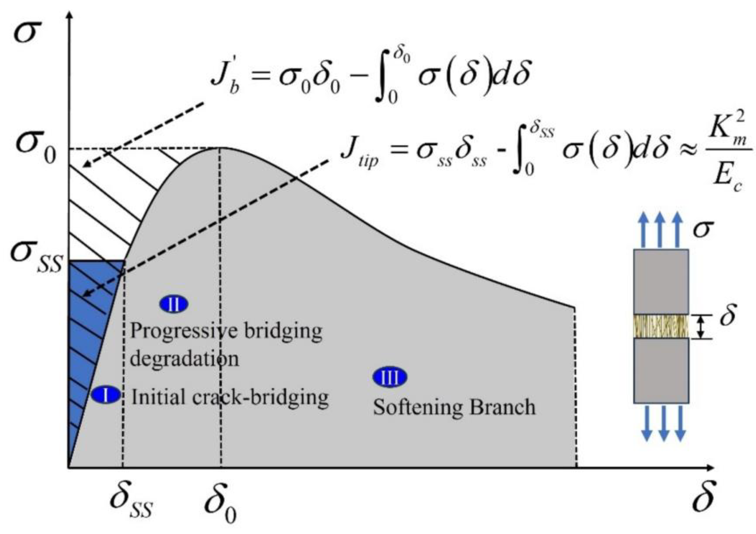
Figure 2.
The performance-driven design approach (PDDA) of SHCC (Modified based on [35]).
Figure 2.
The performance-driven design approach (PDDA) of SHCC (Modified based on [35]).
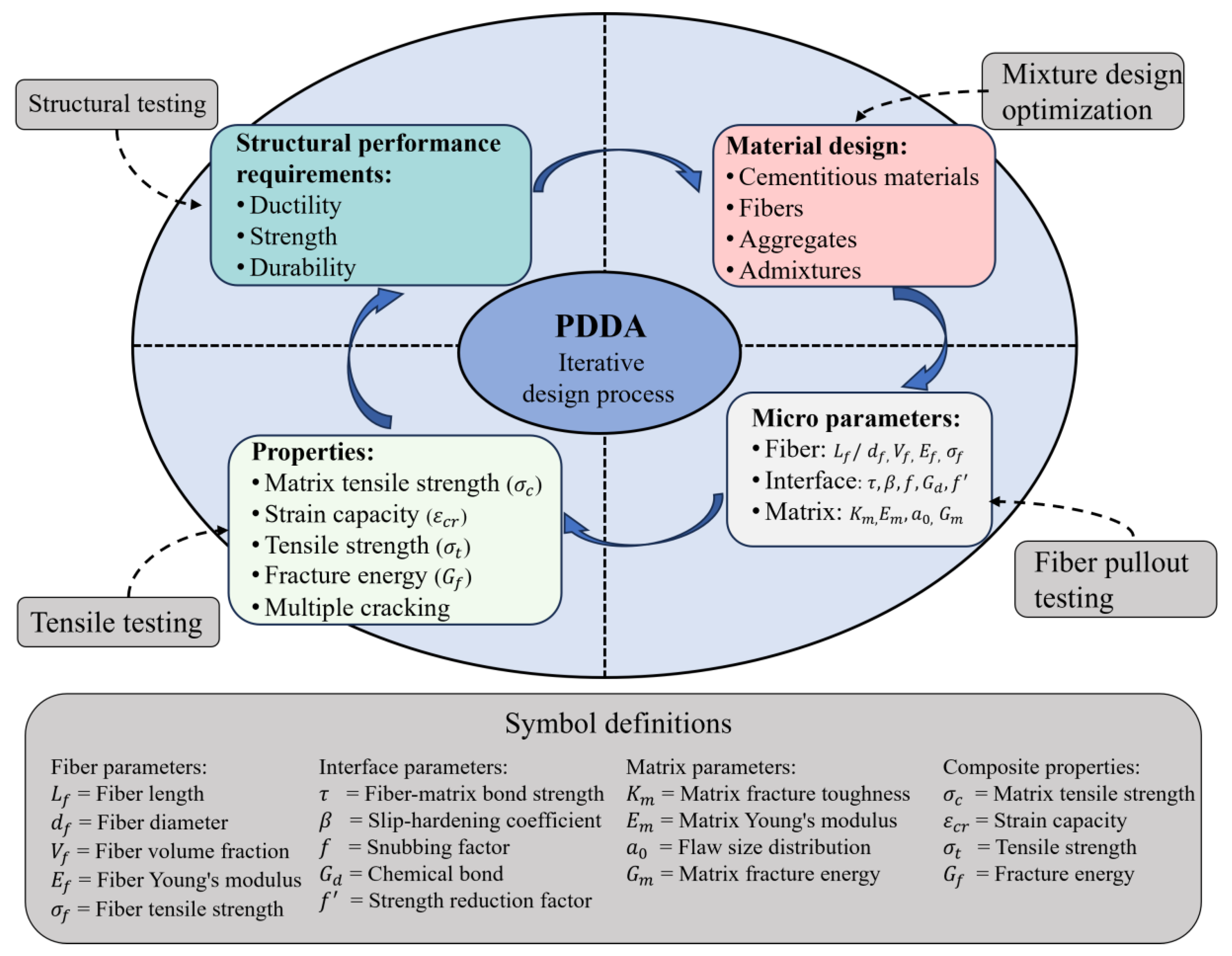
Figure 3.
Coordination of rheological parameters for sprayed SHCC.
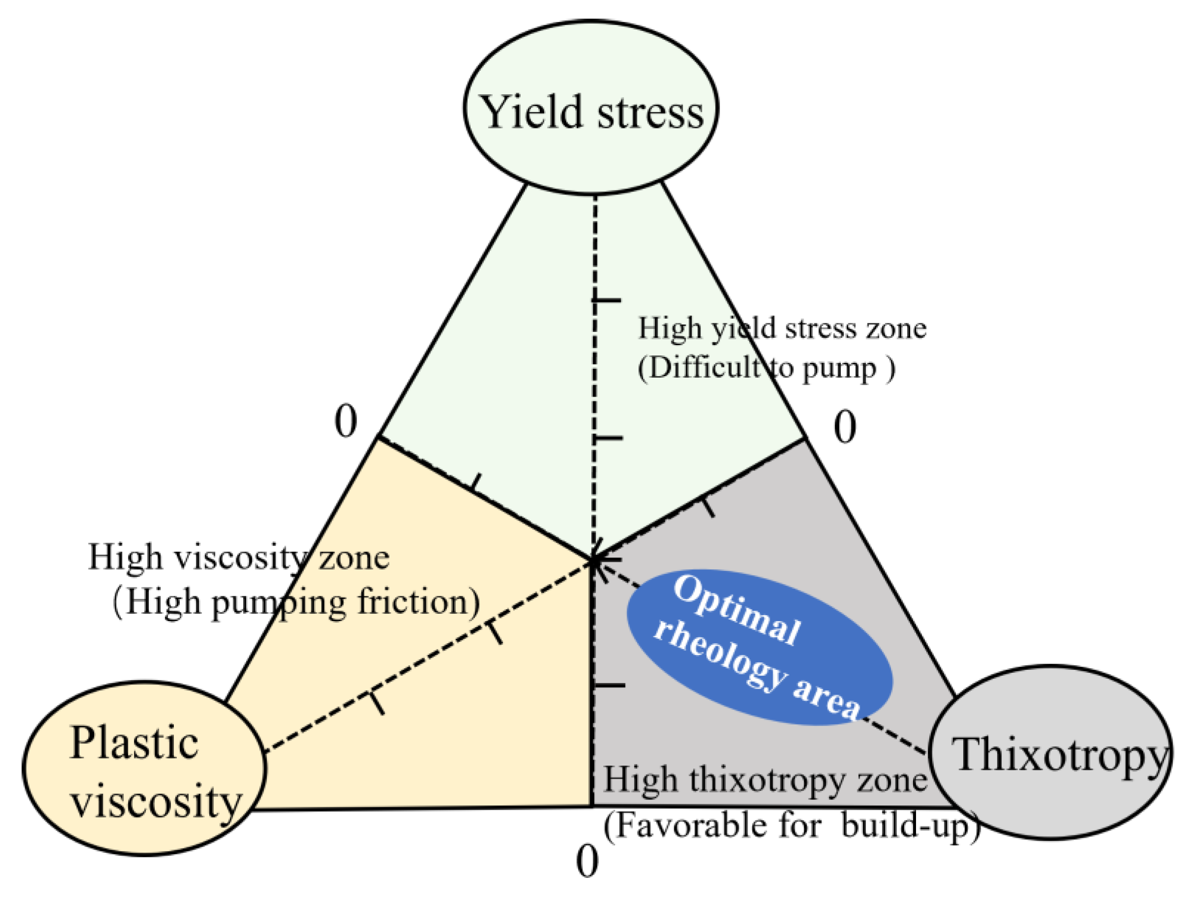
Figure 4.
Design and deformability requirements for sprayed SHCC (Modified based on [39]).
Figure 4.
Design and deformability requirements for sprayed SHCC (Modified based on [39]).
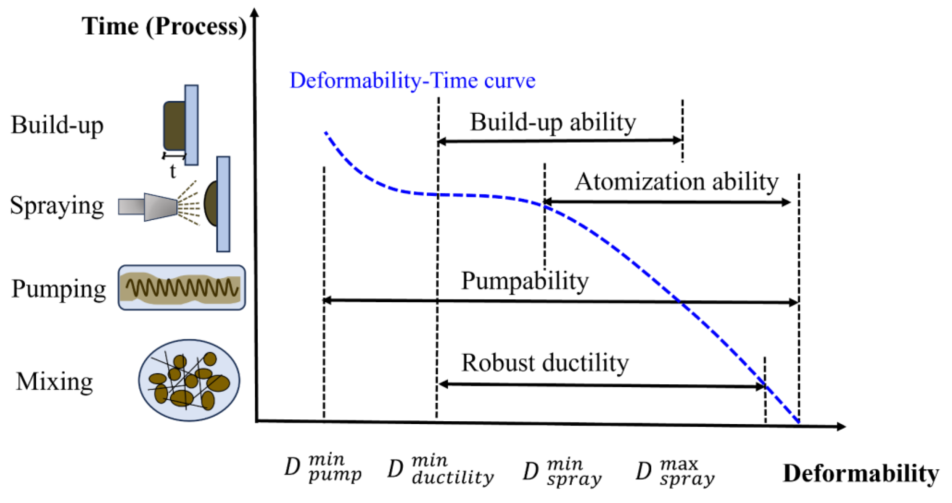
Figure 5.
The flexible fiber behavior in flowing SHCC.
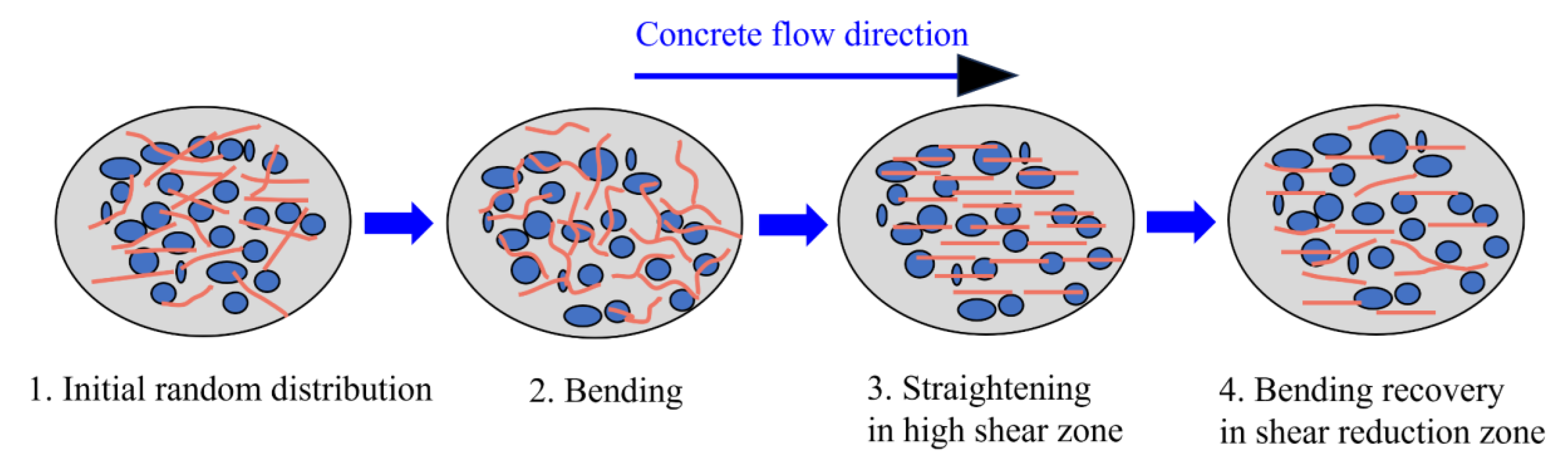
Figure 6.
Rheology-based mixture design process for sprayed SHCC.
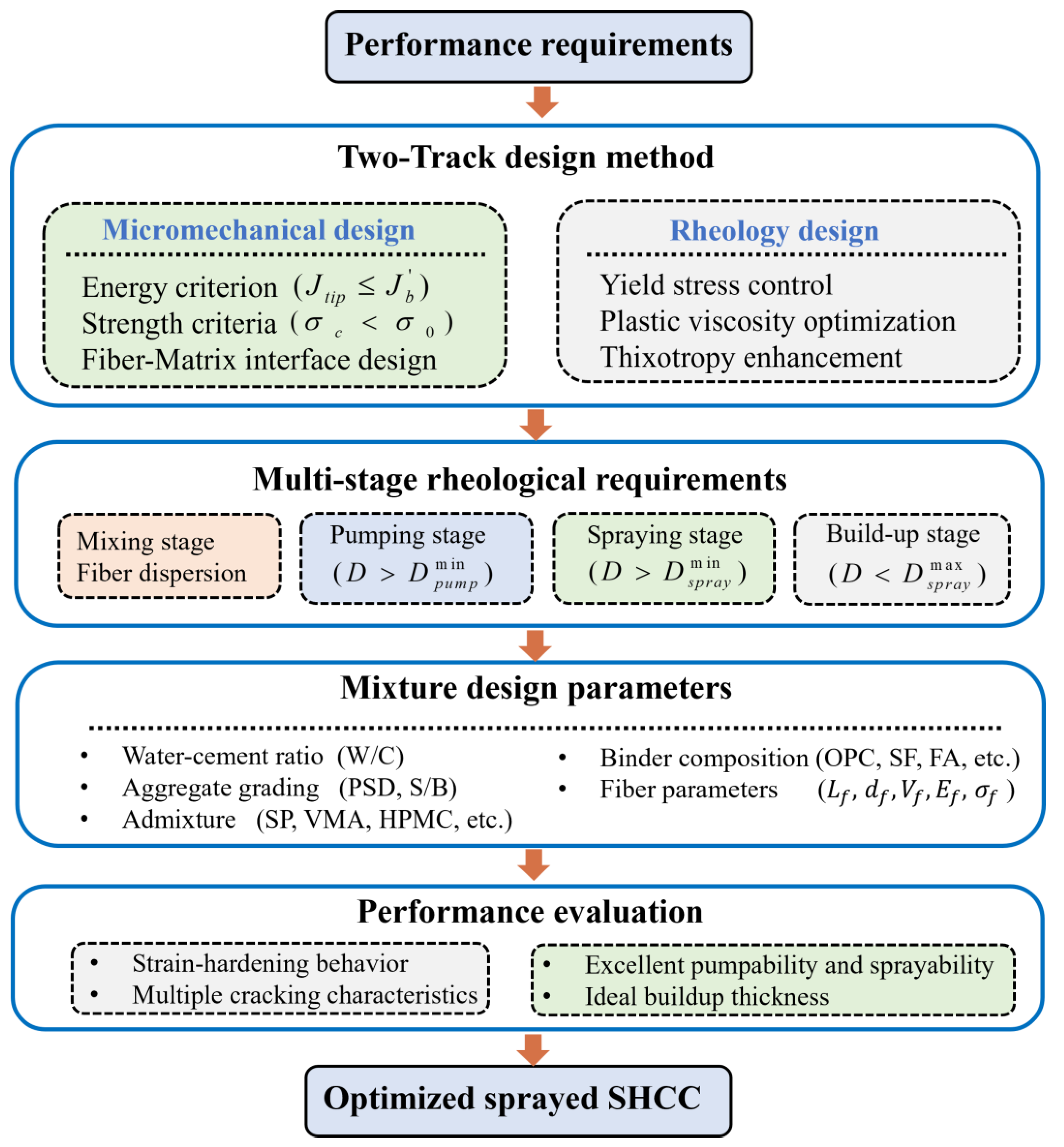
Figure 7.
Schematic of the increase in flaw size in SHCC [69].
Figure 7.
Schematic of the increase in flaw size in SHCC [69].
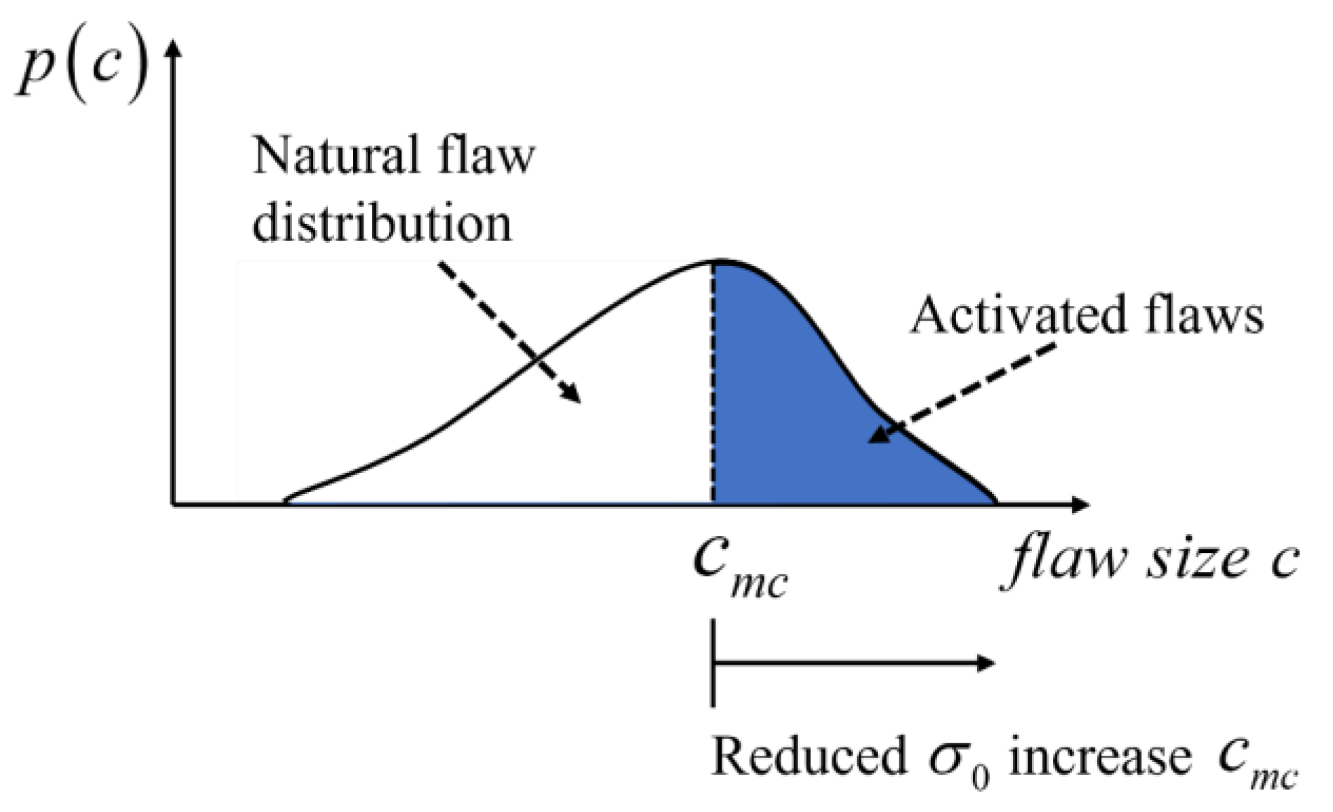
Figure 8.
Fiber dispersion coefficient at different levels of matrix plastic viscosity [69].
Figure 8.
Fiber dispersion coefficient at different levels of matrix plastic viscosity [69].
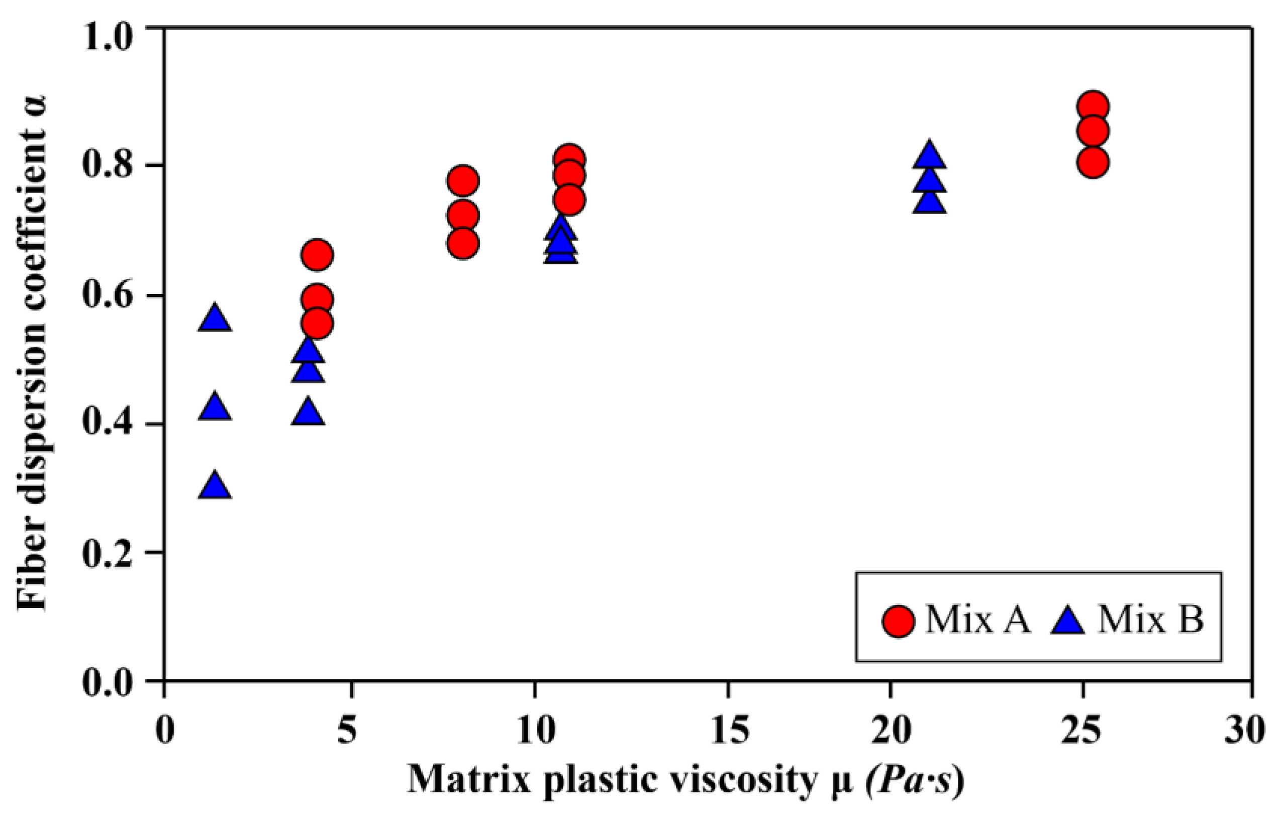
Figure 9.
Single fiber pullout load-displacement curve in SHCC (Modified based on [87]).
Figure 9.
Single fiber pullout load-displacement curve in SHCC (Modified based on [87]).
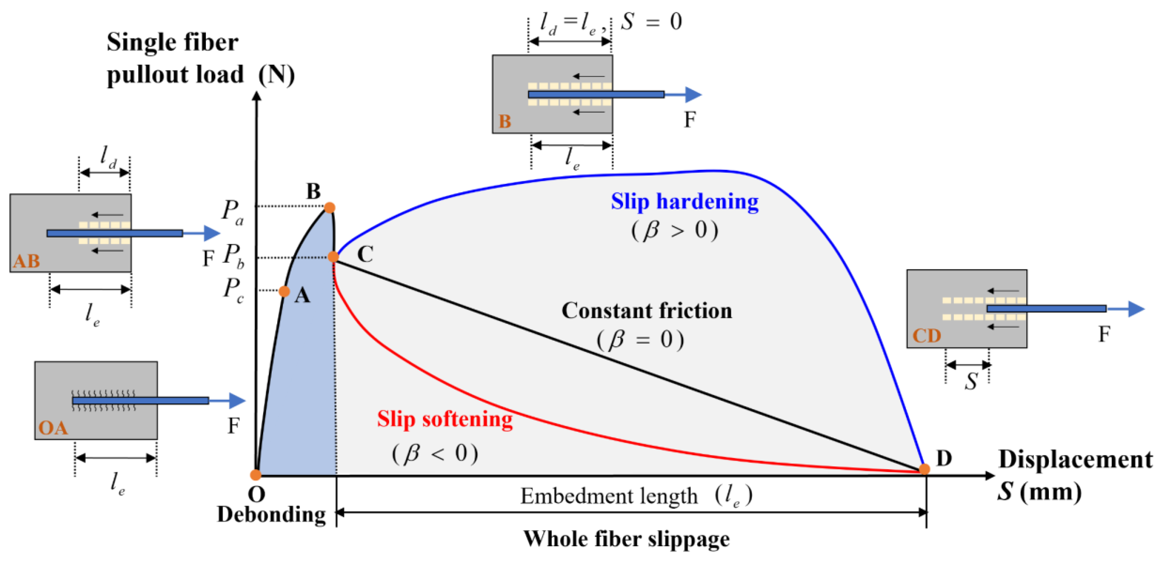
Figure 10.
Polymer structure of PVA fibers and SEM image of fiber surface enriched with hydration products [89].
Figure 10.
Polymer structure of PVA fibers and SEM image of fiber surface enriched with hydration products [89].
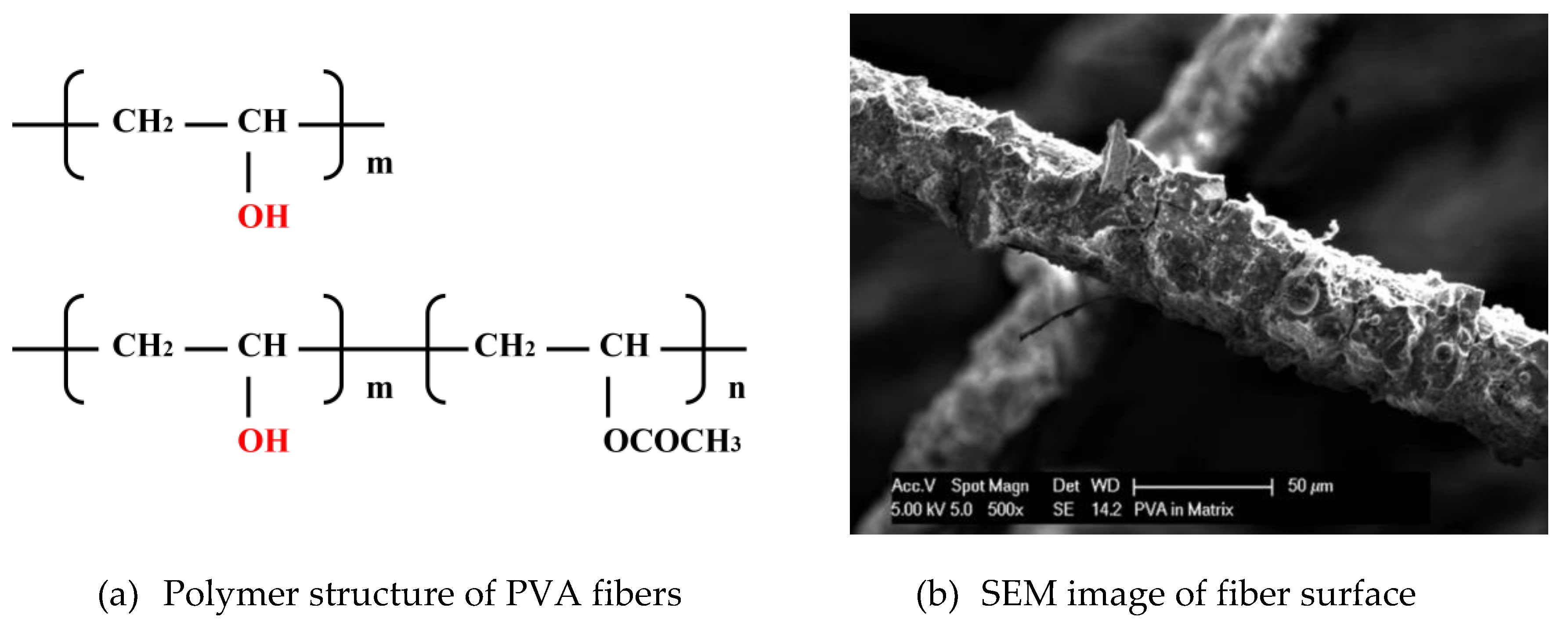
Figure 11.
Schematic diagram of cement hydration with shotcrete accelerator (Modified based on [109]). G: gypsum, P: portlandite.
Figure 11.
Schematic diagram of cement hydration with shotcrete accelerator (Modified based on [109]). G: gypsum, P: portlandite.
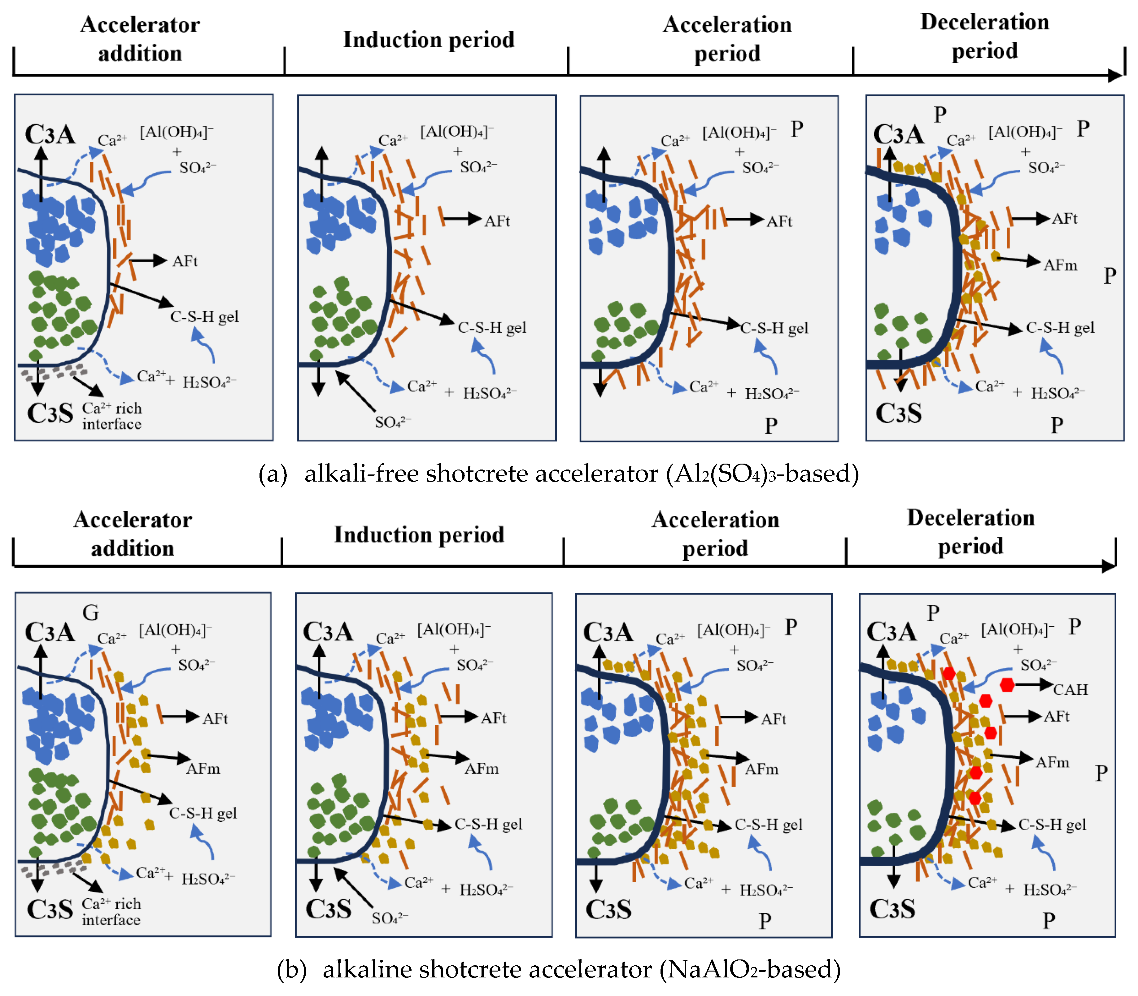
Figure 12.
The phase evolution of cement paste containing 3% accelerator within 48 hours [114].
Figure 12.
The phase evolution of cement paste containing 3% accelerator within 48 hours [114].
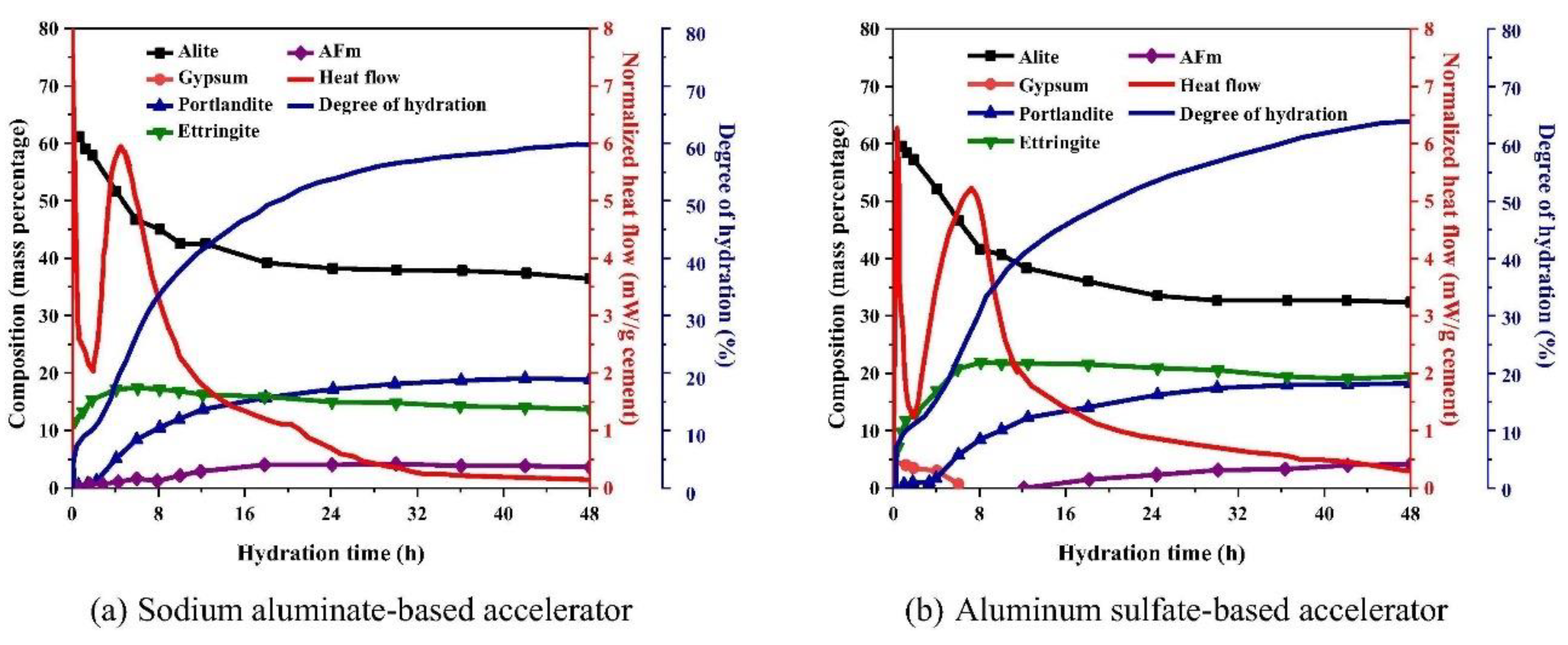
Figure 13.
Mixing and spray processes of shotcrete.
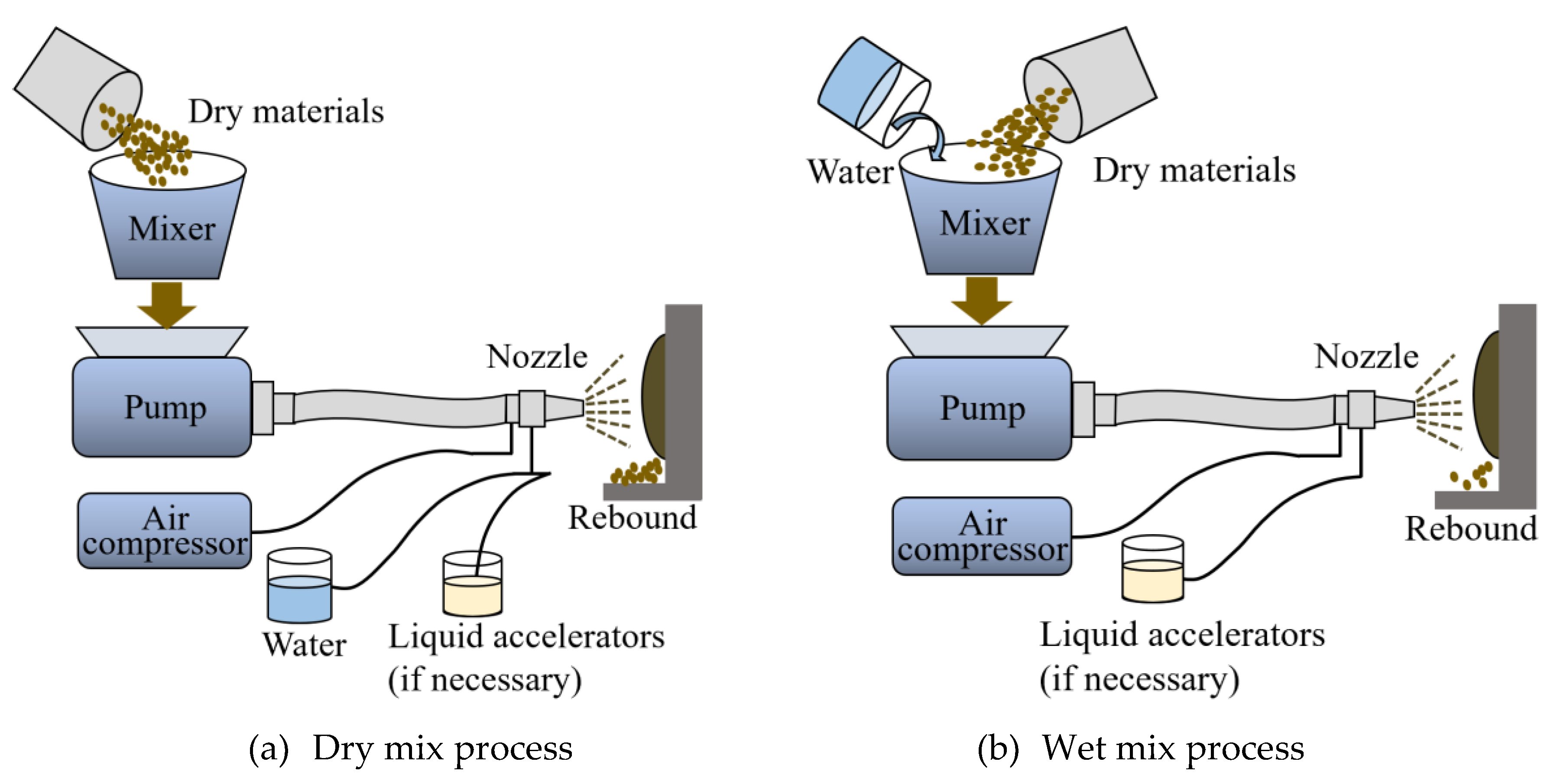
Figure 14.
Schematic demonstration of sprayed-SHCC wet lay-up spray process.
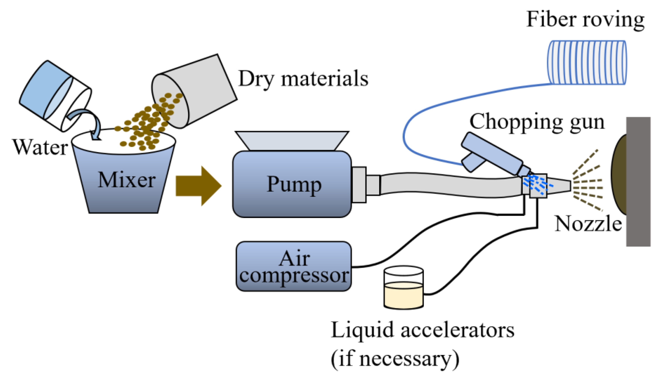
Figure 15.
Spray flow of sprayed SHCC at different airflow and air pressure [9].
Figure 15.
Spray flow of sprayed SHCC at different airflow and air pressure [9].
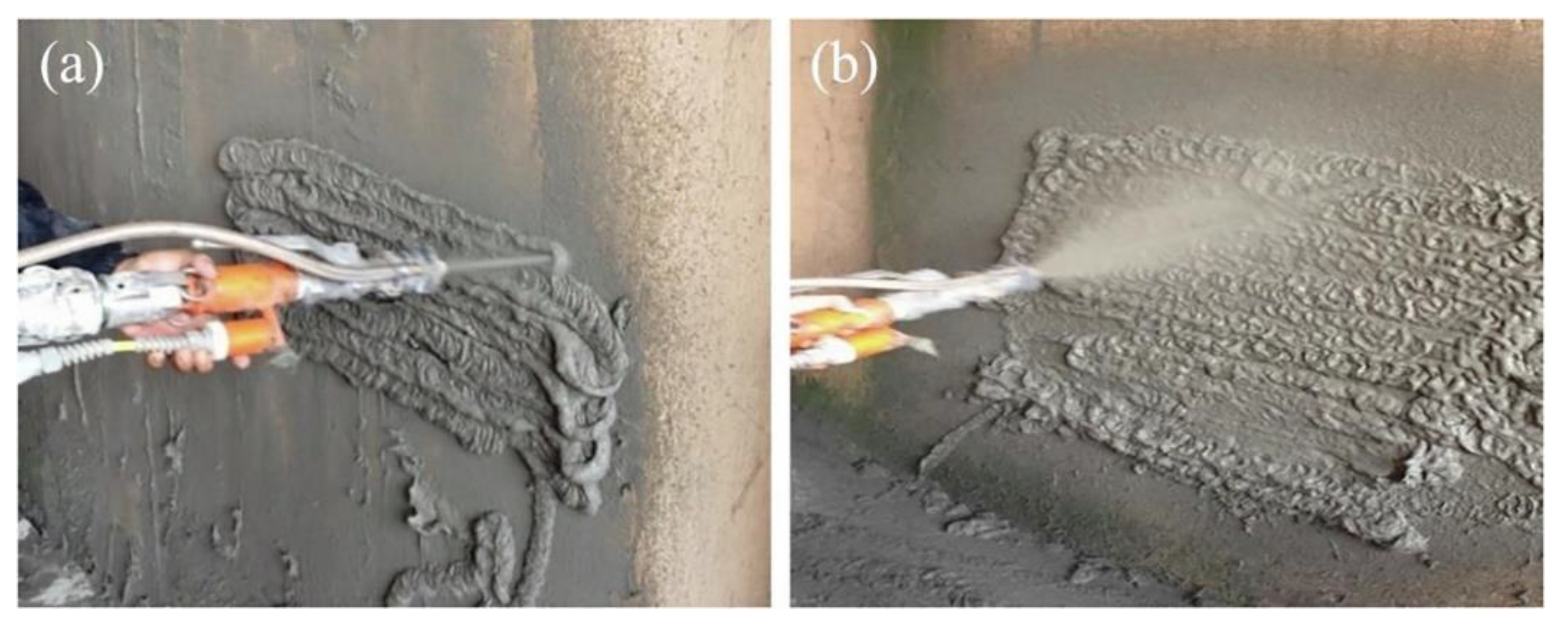
Figure 16.
Schematic diagram of the lubrication layer in a shotcrete pipe (Modified based on [130]).
Figure 16.
Schematic diagram of the lubrication layer in a shotcrete pipe (Modified based on [130]).
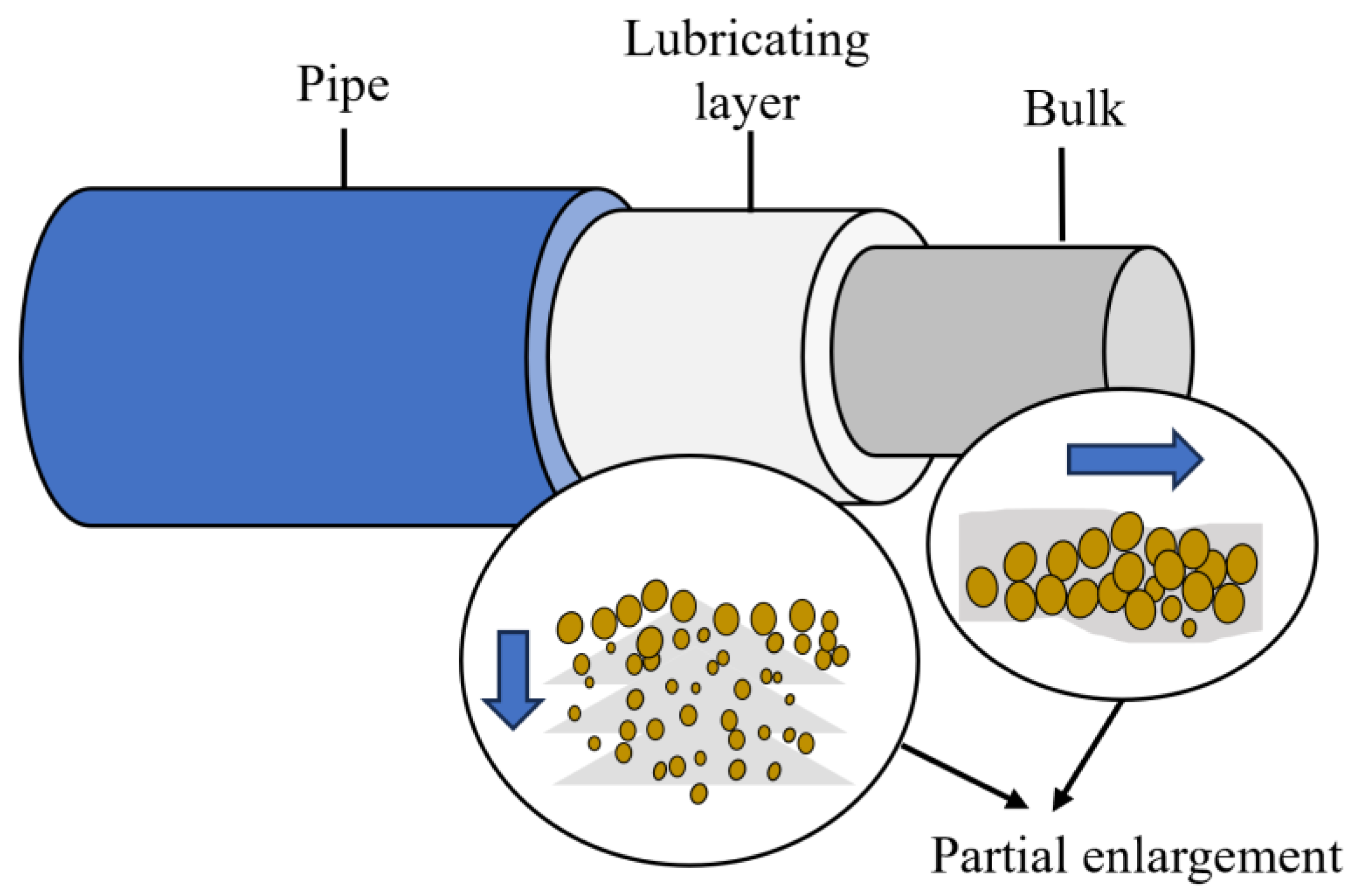
Figure 17.
Schematic representation of lubricating layer formation in a pipeline due to flow-induced particle migration in pumped concrete (Modified based on [131]).
Figure 17.
Schematic representation of lubricating layer formation in a pipeline due to flow-induced particle migration in pumped concrete (Modified based on [131]).
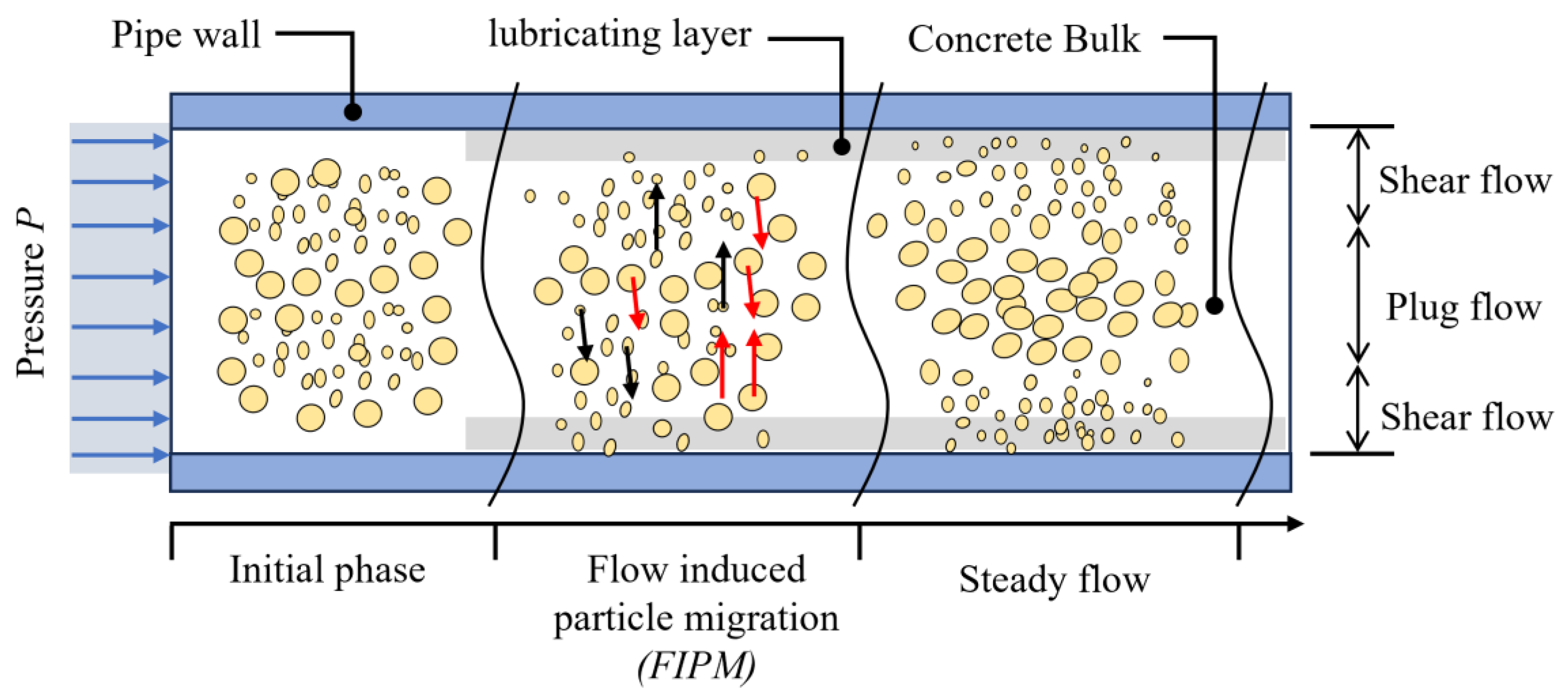
Figure 18.
Pressure-flow rate relationship in the different lengths of a full-scale test [146].
Figure 18.
Pressure-flow rate relationship in the different lengths of a full-scale test [146].
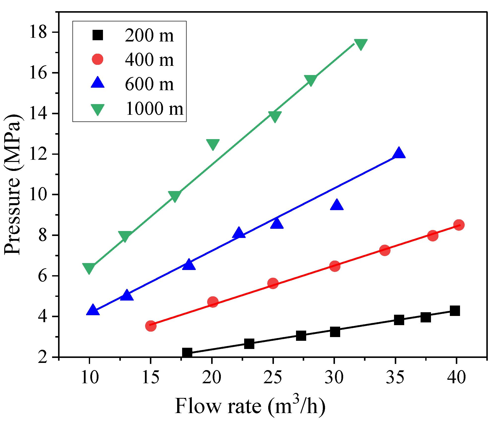
Figure 19.
Schematic of shotcrete build-up thickness (Modified based on [14]).
Figure 19.
Schematic of shotcrete build-up thickness (Modified based on [14]).
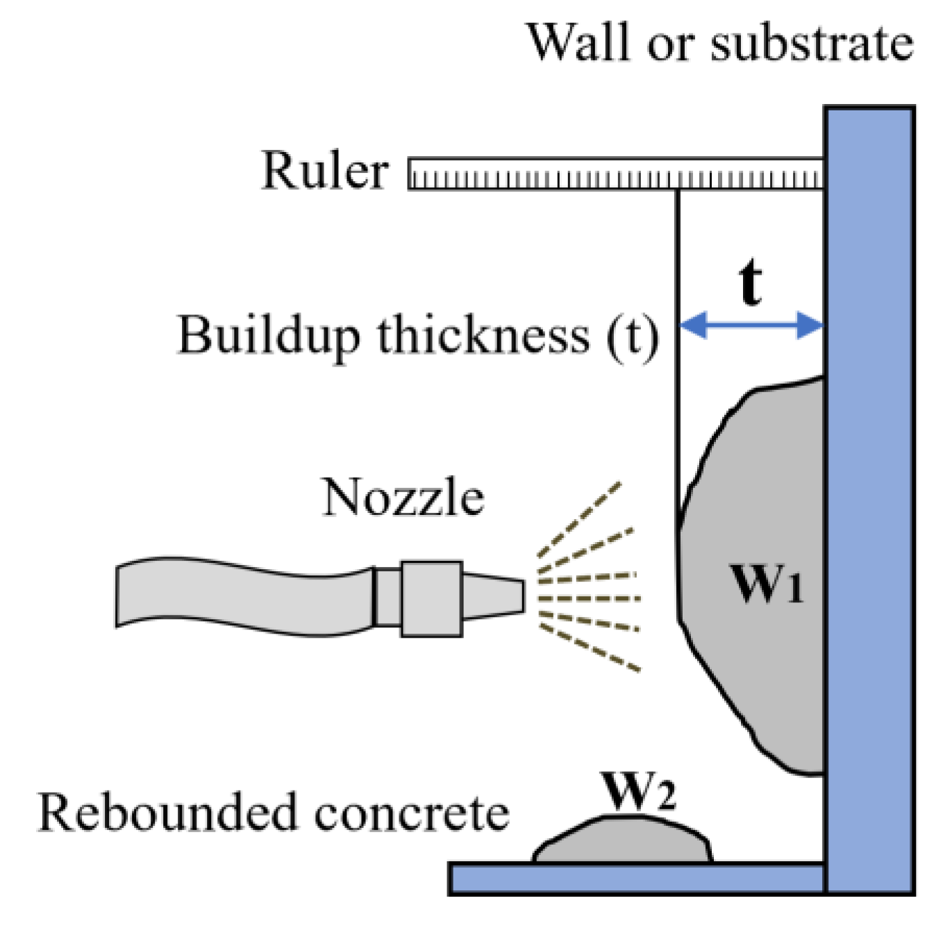
Figure 20.
Failure mode of sprayed SHCC (Modified based on [147]).
Figure 20.
Failure mode of sprayed SHCC (Modified based on [147]).
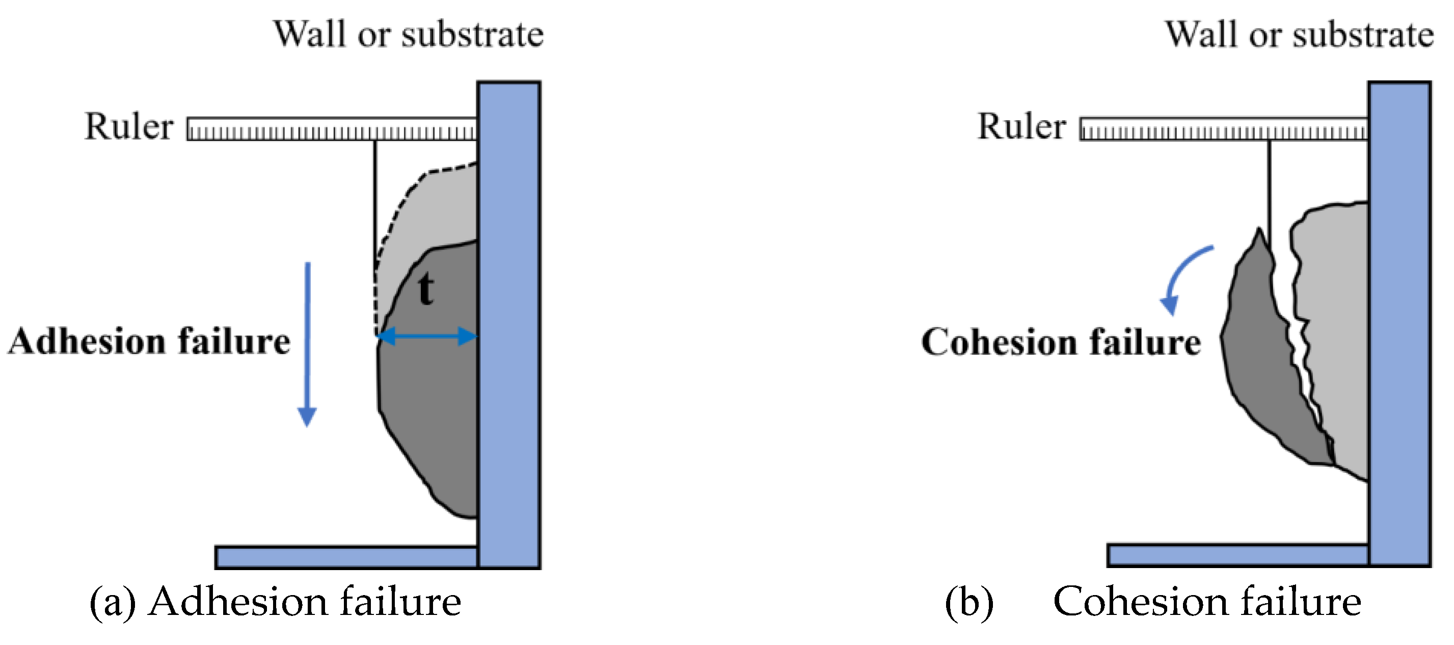
Figure 21.
Tail swing of the polymer fiber upon impact with the substrate surface [10].
Figure 21.
Tail swing of the polymer fiber upon impact with the substrate surface [10].
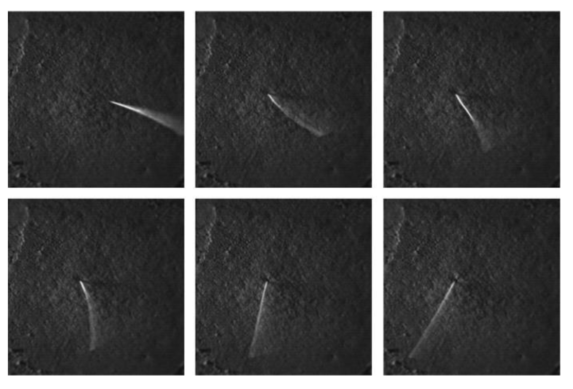
Figure 22.
Flexural and tensile stress-strain curves of sprayed SHCC [75].
Figure 22.
Flexural and tensile stress-strain curves of sprayed SHCC [75].
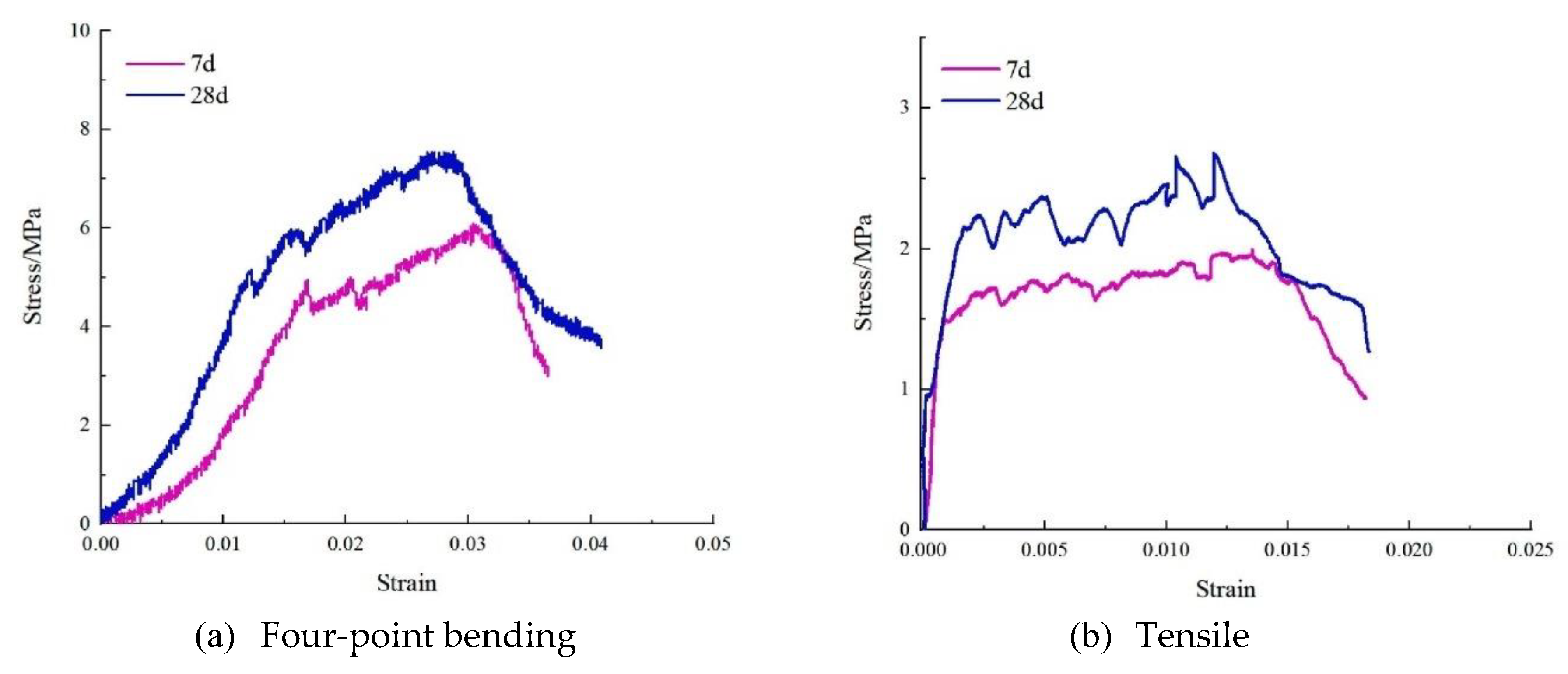
Figure 23.
Tensile stress-strain and flexural deflection curves of sprayed and cast SHCC at 28 days [9].
Figure 23.
Tensile stress-strain and flexural deflection curves of sprayed and cast SHCC at 28 days [9].
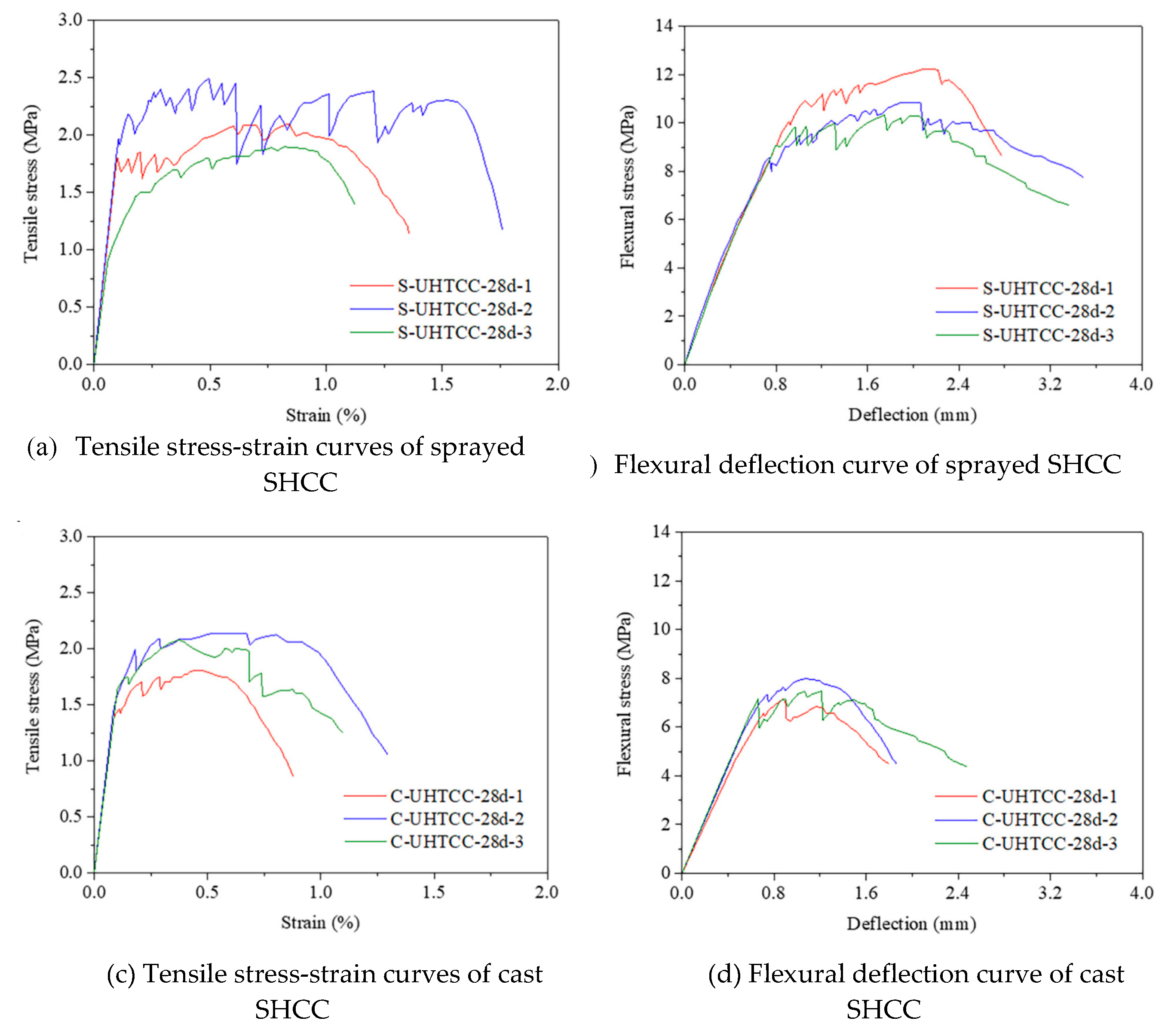
Figure 24.
SEM images of the OTZ with an overlay on top and substrate at the bottom [19].
Figure 24.
SEM images of the OTZ with an overlay on top and substrate at the bottom [19].
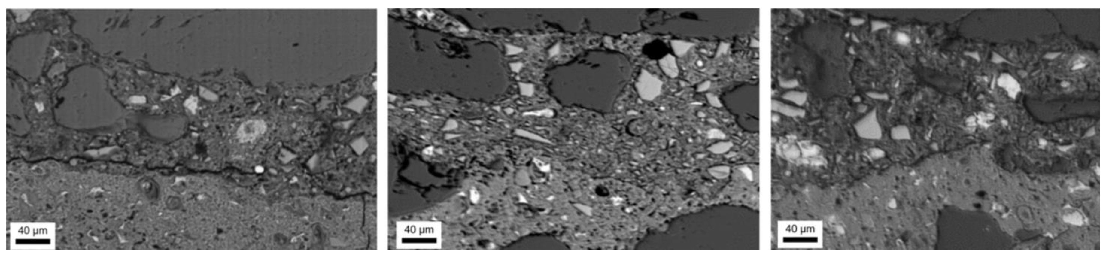
Figure 25.
Interfacial bond strength test methods for sprayed SHCC [164].
Figure 25.
Interfacial bond strength test methods for sprayed SHCC [164].
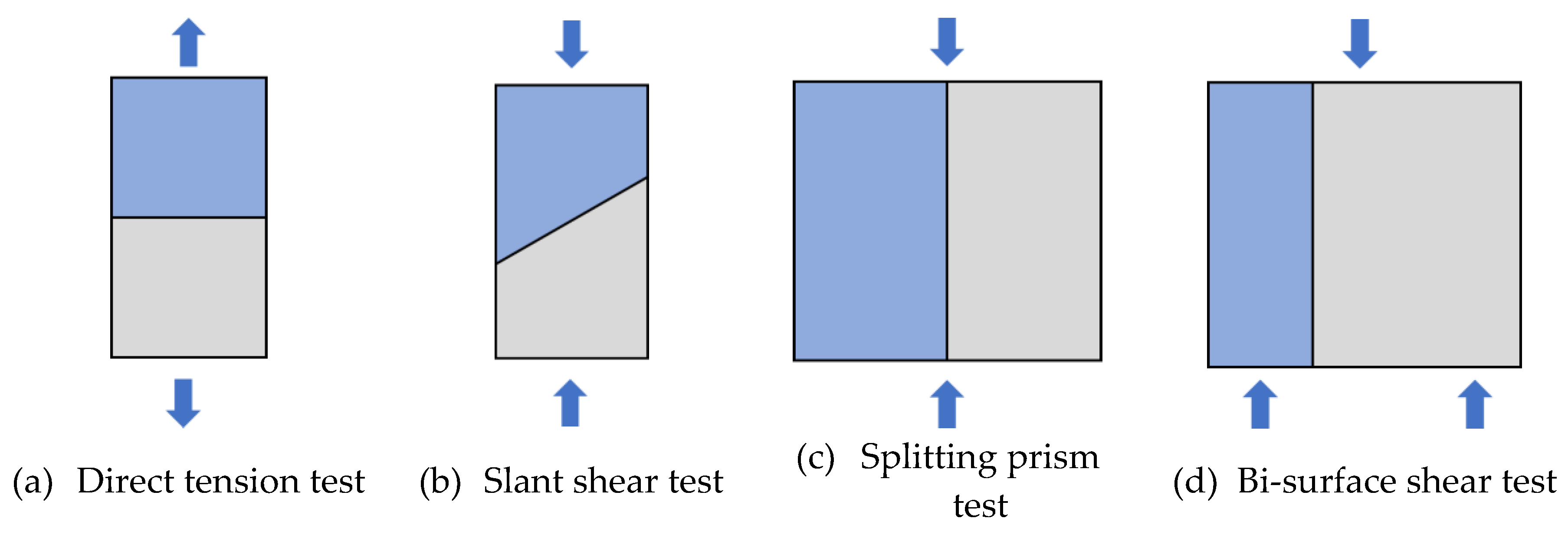
Figure 26.
Failure mode of sprayed SHCC with concrete substrate under shear loading [21].
Figure 26.
Failure mode of sprayed SHCC with concrete substrate under shear loading [21].
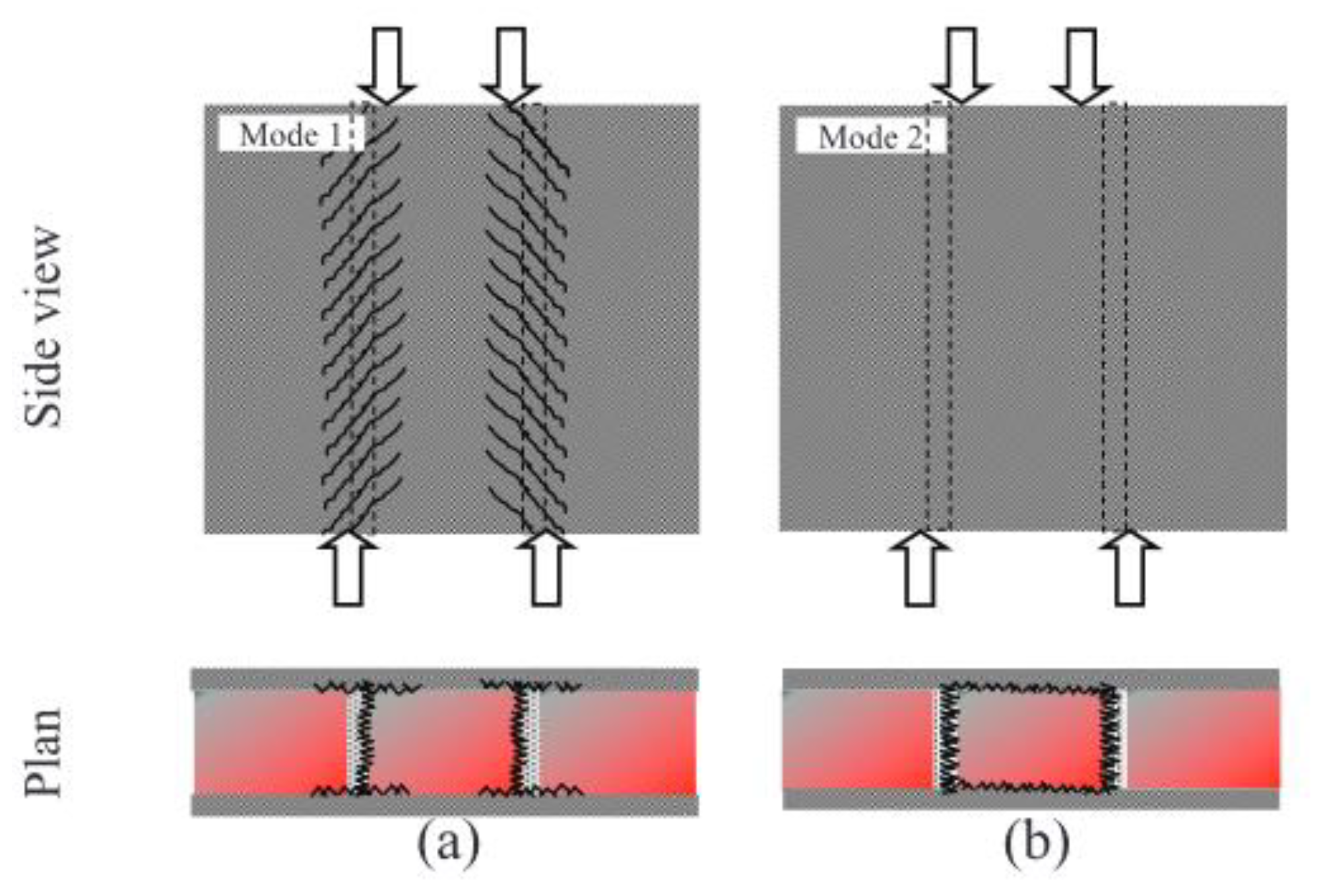
Figure 27.
Comparison of shear load-slip curves of cast and sprayed SHCC [166].
Figure 27.
Comparison of shear load-slip curves of cast and sprayed SHCC [166].
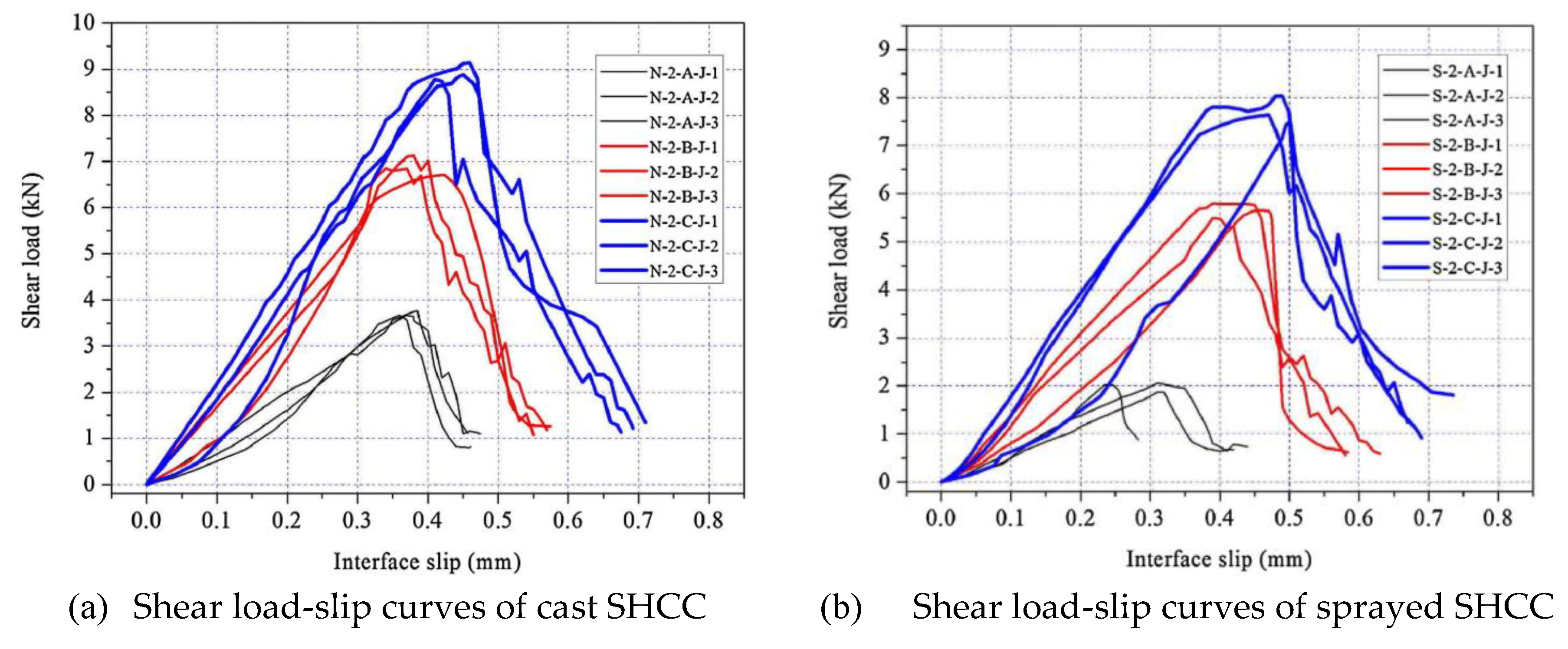
Figure 28.
Schematic diagram of load direction and in- and out-of-plane for sprayed SHCC-reinforced walls (Modified based on [26]).
Figure 28.
Schematic diagram of load direction and in- and out-of-plane for sprayed SHCC-reinforced walls (Modified based on [26]).
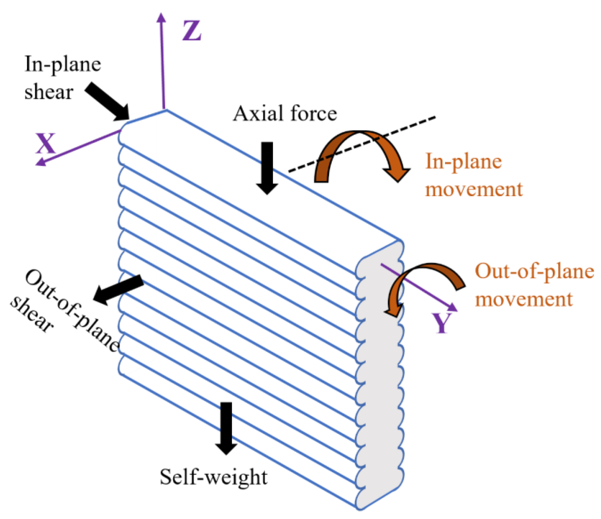

Table 1.
Modification methods and principles for PVA and PE fiber.
| Classification | Methods | Apply to PVA fibers | Apply to PE fibers | Ref. |
| Surface coating treatment | Oil agent treatment; Polymer coating; Nanoparticle coating | Coating hydrophobic substances to reduce exposure of surface OH- and chemical bonding of fibers to Ca+ | Coating hydrophilic substances to enhance surface polarity | [88, 91, 92] |
| Chemical modification | Oxidation/reduction; Acid/alkali treatment; Acetylation | Converting hydroxyl groups to hydrophobic structures; controlling hydroxyl reactivity | Introducing polar groups; increasing surface roughness (acetylation is not applicable) | [93-95] |
| Molecular grafting modification | Surface grafting; Silane coupling agent treatment |
Grafting hydrophobic groups/silanes to reduce interfacial bonding | Grafting hydrophilic monomers/silanes to enhance compatibility | [96, 97] |
| Physical modification | UV irradiation; Plasma technology; Thermal treatment; Corona discharge treatment |
Degrading hydroxyl groups; decreasing surface energy; controlling crystallinity | Inducing oxidation; introducing polar groups; increasing roughness and surface polarity | [98-101] |
Table 2.
Typical specimen sizes and test methods for tensile properties of SHCC [24].
Table 2.
Typical specimen sizes and test methods for tensile properties of SHCC [24].
| Specimen size (mm) and shape | Thickness (mm) | Number of tests | Loading rate |
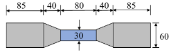 |
13 | ≥5 | 0.5 mm/min |
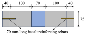 |
Cylinders with a diameter of 75 mm | – | 3 mm/min |
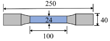 |
40 | 4 | 3 mm/min |
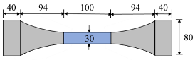 |
20 | 6 | 0.5 mm/min |
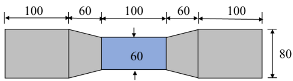 |
100 | 6 | 0.5 mm/min |
Table 3.
Key factors influencing the flexural and tensile properties of sprayed SHCC.
| Factor | Mechanism | Ref. |
| Matrix rheology | Improves pumping, atomization, and fiber dispersion, reducing voids and enabling strain-hardening. | [39] |
| Fiber characteristics | Fiber type, volume fraction, and aspect ratio affect crack-bridging and load transfer. | [9] |
| Fiber orientation & distribution | Fiber alignment and packing density variations result in anisotropic mechanical response. | [18] |
| Mixture composition | Binder, admixtures, and proportions influence hydration, microstructure, shrinkage, and ductility. | [39, 75, 159] |
| Spraying parameters | Air pressure, nozzle design, and spray direction influence atomization and fiber dispersion. | [39] |
| Temperature & curing conditions | Affects hydration kinetics, microstructure, and fiber-matrix interface performance. | [160] |
Table 4.
Key factors influencing the interfacial bond between sprayed SHCC and concrete substrates.
| Factor | Observed effect | Ref. |
| Spraying direction & layer thickness | Upward spraying yields the lowest OTZ bond; layer thickness >25 mm is prone to overlay spalling. | [125] |
| Substrate roughness & surface preparation | Sandblasting enhances mechanical interlock, increasing shear and tensile bond strengths. | [163] |
| Substrate moisture condition | Dry substrate surfaces absorb water from the overlay, reducing OTZ hydration and mechanical interlock. | [19] |
| Cementitious material type | >10% replacement of CEM I 52.5 with CAC improves early-age adhesion. | [21] |
| Aggregate content | Low aggregate content reduces shrinkage restraint; if strain > tensile strain capacity, debonding occurs. | [21] |
| Flowability of sprayed SHCC | Excessive flowability induces shrinkage and stress concentration, causing interfacial cracking. | [20] |
| Curing conditions | Inadequate curing restricts the progression of cement hydration, thereby impeding the development of a dense OTZ. | [19, 20] |
Disclaimer/Publisher’s Note: The statements, opinions and data contained in all publications are solely those of the individual author(s) and contributor(s) and not of MDPI and/or the editor(s). MDPI and/or the editor(s) disclaim responsibility for any injury to people or property resulting from any ideas, methods, instructions or products referred to in the content. |
© 2025 by the authors. Licensee MDPI, Basel, Switzerland. This article is an open access article distributed under the terms and conditions of the Creative Commons Attribution (CC BY) license (http://creativecommons.org/licenses/by/4.0/).
Copyright: This open access article is published under a Creative Commons CC BY 4.0 license, which permit the free download, distribution, and reuse, provided that the author and preprint are cited in any reuse.


