
Submitted:
29 September 2025
Posted:
01 October 2025
You are already at the latest version
Abstract
Background/Objectives: Mini-Screw-Assisted Rapid Skeletal Expansion (MARPE) appliances have been widely used to provide maxillary skeletal expansion in non-growing subjects and adolescents with a fused midpalatal suture. The current case report describes the immediate 3D cephalometric changes in the skeletal and soft tissue parameters, along with upper airway volume, shape, and dimensions, in a patient with Skeletal Class I anterior underbite. Methods: The pre- and post-expansion full-face Cone-Beam Computed Tomograms (CBCTs) of the 19-year-old patient who underwent 3D-guided midpalatal piezocorticotomy-assisted MARPE were compared and analyzed with 3D cephalometric software. Both CBCT volumes were re-oriented relative to the Frankfurt Horizontal Plane (FHP) to ac-commodate the postural changes. Results: The total upper airway volume and upper airway minimum cross-section increased after expansion. The nasal base plane (ANS–PNS) rotated in all three spatial planes, including the sagittal plane (anterior downward and posterior upward rotation, with the center of rotation around the maxillary center of rotation) and the vertical plane (rotated upward on the left side). The maxillary canine and molar cant planes rotated around the center of rotation in the midface, with left upward and right downward rotation. The orientation of the ANS–PNS plane changed due to the leftward rotation of the ANS, with the center of rotation approaching the PNS. Cervical curvature improved from kyphotic to lordotic immediately following expansion. Conclusions: Three-dimensional-guided mid-palatal piezocorticotomy-assisted MARPE has been shown to produce midfacial changes in all three spatial planes when evaluated via 3D cephalometric analysis. Comprehensive observational studies are necessary to analyze these changes and their effects on different skeletal classifications.
Keywords:
MARPE
; guided midpalatal piezocorticotomy
; adults
; 3D analysis
; cephalometrics
; upper airway
1. Introduction
Mini-Screw-Assisted Rapid Skeletal Expansion (MARPE) appliances have been widely used to provide maxillary skeletal expansion in non-growing subjects and adolescents with a fused midpalatal suture [1], [2], [3]. Auxiliary techniques have been suggested to augment the midpalatal suture separation procedure in adult patients [4], [5].
Nasal cavity measurements of MARPE are typically performed in the area of the ANS, the PNS, the nasal septum deviation angle [6], and pharyngeal volumes. Nasal respiratory parameters were systematically reviewed by Arqub and coauthors [7], who did not find any correlation between nasal airflow and the transverse anatomical measurements of the upper airway produced by MARPE. Cantarella and colleagues showed a statistically significant increase in nasal cavity volume and nasopharyngeal dimensions following MARPE [8].
Most authors agree on the correlation between the upper airway shape and skeletal classification [9], [10]. For example, Skeletal Class II patients show a lower position of the hyoid bone, with a smaller oropharyngeal airway minimum cross-section; while those with Skeletal Class III have smaller dimensions of the nasopharyngeal airway and a higher position of the hyoid bone.
One study attributed forward head posture to compensation for the decreased upper airway dimensions in the context of the prevalence of anterior TMJ disc displacement [11]. The authors of this study referred to Skeletal Class II as a prerequisite for anterior cervical extension as part of an effort to achieve upper airway size compensation.
Paredes and colleagues [12] suggested novel angular measurements to assess the forward–outward rotation of the maxillary complex with Maxillary Skeletal Expander (MSE) treatment in the coronal plane. A study by Cantarella [13] and colleagues supported the idea of clockwise mandibular rotation with MSE treatment.
The current case report describes immediate 3D cephalometric changes in the skeletal and soft tissue parameters, along with upper airway volume, shape, and dimensions, in a patient with a Skeletal Class I anterior underbite.
2. Materials and Methods
A 19-year-old male patient with an underdeveloped midface and underbite presented for treatment with 3D-guided midpalatal piezocorticotomy with custom MARPE [5]. Further orthodontic treatment with a direct printed aligner is to be rendered after the initial expansion and will not be discussed in this case report.
Initial records included the CBCT of the head and neck. The full face CBCT was taken with a Planmeca Viso G7 (Planmeca, Helsinki, Finland) at 30 Sv-6, 100 kV, and a 600 Voxel Ultra Low Dose (ULD) setting slice with a 19’’x19’’ sensor area with the patient in an upright position with natural head posture and occipital head support. A pre-treatment lateral cephalometric radiograph was rendered from the CBCT, traced, and evaluated via Roth–Jarabak analysis (Table 1, Fig. 1.).
Consent for this study was obtained before treatment.
The 3D guide for the midpalatal piezocorticotomy was three-dimensionally designed and printed based on the patient’s initial CBCT and intraoral scan imaging. The precise positions of the incision notches and the depth of incision were calculated.
The 3D-guided midpalatal piezocorticotomy procedure and the custom MARPE positioning was undergone under topical anesthesia—20% Benzocaine topical anesthesia and 0.5% 1:200k epi Marcaine infiltration anesthesia. The piezocorticitomy cuts were performed immediately after anesthesia onset with the Mectron piezotome (Mectron, Hilliard, USA) and individually designed based on the 3D-printed piezocorticotomy guide. The ULD CBCT of the maxillary area was taken to confirm the depth and the location of the piezocorticotomy along with the custom MARPE screw positioning (Fig. 2).
The custom MARPE design included a 12 mm power screw (TigerDenatl, Horbranz, Austria) with 2 turns/day activation until the initial split, 1 turn/day activation for the next 3 weeks, and 1 turn/3 days activation for 3 more weeks. (Fig. 3)
Post-expansion records included CBCT taken with identical parameters to those initially employed (19’’x19’’ sensor area, Planmeca Viso G7, NHP).
3. Results
Both CBCT scans were digitally analyzed in all spatial planes to determine any changes applicable to 3D-guided midpalatal piezocorticotomy-assisted MARPE.
The midpalatal disarticulation resulted in parallel separation of the midpalatal suture at all points, including the ANS and PNS (Fig. 4).
The 3D cephalometric measurements were grouped into the following:
- i.
- Sagittal: ANS to TVL; Mx incisor R to TVL; Mx incisor L to TVL; upper right canine to TVL; upper left canine to TVL; upper right molar to TVL; upper left molar to TVL; pogonion to TVL; B-point to TVL; PNS to TVL (Table 1).
- ii.
- Canting: Mx33 cant.
- iii.
- Width difference: width difference, Mx molar; width difference, Zyg Arch; width difference, Lat Orb Rim.
- iv.
- Transverse: Mx molar R width; Mx molar L width; Zyg Arch R width; Zyg Arch L width; Lat Orb Rim R width; Lat Orb Rim L width.
- v.
- Vertical: Mx incisor height; Mx canine R height; Mx canine L height; Mx molar R height; Mx molar L height; pogonion height; PNS height, menton height.
- vi.
- Soft tissue: RChkbone; LChkbone; Rnasalbase; Lnasalabase.
- vii.

Table 2.
Three-dimensional cephalometric measurements and their descriptions used for the analysis.
| Measurement | Description |
| ANS to TVL | Distance from ANS to True Vertical Plane (TVL) through Sn (Subnasal) |
| Mx Incisor R to TVL | Distance from Maxillary Right Central Incisor Tip to TVL (Sn) |
| Mx Incisor L to TVL | Distance from Maxillary Left Central Incisor Tip to TVL (Sn) |
| Upper Right Canine to TVL | Distance from Maxillary Right Canine Tip to TVL (Sn) |
| Upper Left Canine to TVL | Distance from Maxillary Left Canine Tip to TVL (Sn) |
| Upper Right Molar to TVL | Distance from Maxillary Right first Molar Mesiofacial Cusp Tip to TVL (Sn) |
| Upper Left Molar to TVL | Distance from Maxillary Left first Molar Mesiofacial Cusp Tip to TVL (Sn) |
| Pogonion to TVL | Distance from Pogonion to TVL (Sn) |
| B-Point to TVL | Distance from Point B to TVL (Sn) |
| PNS to TVL | Distance from PNS to TVL (Sn) |
| Mx33 cant | Cant of the Maxillary Canine Plane (Positive—Right Side Down; Negative—Left Side Down) |
| Width difference Mx molar | Width Difference between the Right and Left Measurements of the Maxillary Molar Width |
| Width difference Zyg Arch | Width Difference between the Right and Left Measurements of the Zygomatic Arch Width |
| Width Difference Lat Orb Rim | Width Difference between the Right and Left Measurements of the Lateral Orbital Rim Width |
| Mx Molar R Width | Distance Between the Distofacial Cusp of the Maxillary Right First Molar and Midfacial Plane |
| Mx Molar L Width | Distance Between the Distofacial Cusp of the Maxillary Left First Molar and Midfacial Plane |
| Zyg Arch R Width | Distance Between Right Zygomatic Arch and Midfacial Plane |
| Zyg Arch L Width | Distance Between Left Zygomatic Arch and Midfacial Plane |
| Lat Orb Rim R Width | Distance Between Right Frontozygomatic Suture and Midfacial Plane |
| Lat Orb Rim L Width | Distance Between Left Frontozygomatic Suture and Midfacial Plane |
| Mx Incisor Height | Distance Between the THP (Na) and Maxillary Central Incisor Tip |
| Max Canine R Height | Distance Between the THP (Na) and Maxillary Right Canine Tip |
| Mx Canine L Height | Distance Between the THP (Na) and Maxillary Left Canine Tip |
| Mx Molar R Height | Distance Between the THP (Na) and Maxillary Right First Molar Mesiofacial Cusp Tip |
| Mx Molar L Height | Distance Between the THP (Na) and Maxillary Left First Molar Mesiofacial Cusp Tip |
| Pogonion Height | Distance Between Pogonion and THP (Na) |
| PNS Height | Distance Between PNS and THP (Na) |
| Menton Height | Distance Between Menton and THP (Na) |
| RChkbone | Soft Tissue Distance from the Right Cheekbone to TVP (Sn) |
| LChkbone | Soft Tissue Distance from the Left Cheekbone to TVP (Sn) |
| Rnasalbase | Soft Tissue Distance from the Right Nasal Base to TVP (Sn) |
| Lnasalabase | Soft Tissue Distance from the Left Nasal Base to TVP (Sn) |
The midpalatal suture disarticulation was measured at three points: the ANS, the middle third of the suture, and the PNA. The mean disarticulation was 11.33 mm (Fig. 4).
| The direction and amount of landmark translation in three spatial planes are outlined in Table 3. The overall vector of landmark displacement in the sagittal plane was towards the TVL (forward), decreasing the distance between the landmark and the TVL (depicted as negative values). The canting value remained negative but decreased by 1.1 degrees (showing that the left side was lower than the right side). Width difference values: Positive values denote a predominance of the right side, while negative values denote a predominance of the left side. The width values showed an increase in the width on the left side for the molar width from the midfacial midline and for the zygomatic arch from the midfacial midline, while a lateral orbital rim width increase was noted on the right side. The height values showed a similar vector towards downward translation by increasing the distance from the THP and the points on the surface of the anterior and posterior teeth. A right side downward translation occurred, while on the left side, both canine and molar translation occurred in the opposite direction. Mandibular landmarks followed a similar pattern of downward translation, but to a lesser extent. ANS–PNS plane rotation occurred in a downward direction in the area of the ANS, with an equal and opposite direction in the area of the PNS. While the PNS underwent upward translation, the occlusal surface of only the left first molar and canine followed this pattern. Soft tissue landmarks did not undergo significant changes, with no changes related to the base of the nose, and with opposite changes in the area of the soft tissue outlines of the zygomatic arches. Upper airway changes: Both the upper airway total volume and the upper airway min cross-section increased (Table 4). |
Table 3.
Three-dimensional cephalometric measurements with values before and after expansion and their changes.
Table 3.
Three-dimensional cephalometric measurements with values before and after expansion and their changes.
| Measurement | Before | After | Difference |
| ANS to TVL | -15.1 mm | -10.7 mm | -4.4mm |
| Mx Incisor R to TVL | -16.5 mm | -16.0 mm | -0.5 mm |
| Mx Incisor L to TVL | -19.6 mm | -15.7 mm | -3.9 mm |
| Upper Right Canine to TVL | -21.0mm | -18.5 mm | -2.5 mm |
| Upper Left Canine to TVL | -26.2 mm | -21.7 mm | -4.5 mm |
| Upper Right Molar to TVL | -36.8 mm | -36.2mm | -0.4 mm |
| Upper Left Molar to TVL | -41.3 mm | -41.4 mm | 0.1 mm |
| Pogonion to TVL | -14.7 mm | -16.8 mm | 2.1 mm |
| B-Point to TVL | -14.7 mm | -17.0 mm | 2.3 mm |
| PNS to TVL | 70.6 mm | 68.1 mm | - 2.5mm |
| Mx33 cant | -3.2 degrees | 1.1 degrees | -2.1 degrees |
| Width Difference, Mx Molar | 3.2 mm | -3.7 mm | -0.5 mm |
| Width Difference, Zyg Arch | 3.5 mm | -2.6mm | 0.9 mm |
| Width Difference, Lat Orb Rim | -1.4mm | -1.7 mm | 0.3 mm |
| Mx Molar R Width | 30.8 mm | 32.4 mm | 1.6 mm |
| Mx Molar L Width | 27.7 mm | 36.1 mm | 8.4 mm |
| Zyg Arch R Width | 67.6 mm | 67.7 mm | 0.1 mm |
| Zyg Arch L Width | 67.5 mm | 68.3 mm | 0.8 mm |
| Lat Orb Rim R Width | 45.6 mm | 52.0 mm | 6.4 mm |
| Lat Orb Rim L Width | 46.9 mm | 53.6 mm | 6.7 mm |
| Mx Incisor Height | 71.0 mm | 74.2 mm | 3.2 mm |
| Max Canine R Height | 70.9 mm | 73.0 mm | 2.1 mm |
| Mx Canine L Height | 74.1 mm | 72.0 mm | -1.9 mm |
| Mx Molar R Height | 72.7mm | 73.9 mm | 1.2 mm |
| Mx Molar L Height | 73.8mm | 73.1 mm | -0.7 mm |
| Pogonion Height | 115.5 mm | 117.6 mm | 2.1 mm |
| PNS Height | 55.5 mm | 55.3 mm | -0.2 mm |
| Menton Height | 121.8 mm | 124.2 mm | 2.4 mm |
| RChkbone | 41.1 mm | 35.4 mm | -5.7 mm |
| LChkbone | 39.0 mm | 37.3 mm | -1.7 mm |
| Rnasalbase | 0 | 0 | 0 |
| Lnasalabase | 0 | 0 | 0 |
Table 4.
Upper airway measurements before and after expansion.
| Measurement | Before | After |
| Upper Airway Total Volume, cc | 19.5 | 21.7 |
| Upper Airway Min Cross-section, mm2 | 253 | 307 |
The position of the ANS–PNS plane is sagittal (see Fig. 5.).
The total vectors of the 3D changes introduced via 3D-guided midpalatal piezocorticotomy-assisted MARPE are described in Fig. 6.
Upper airway changes are rendered in Fig. 9.
3. Discussion
Most authors are in agreement in their reporting of the favorable outcomes of MARPE for patients exhibiting features of Skeletal Class III malocclusion [17], [18] in combination with a facemask and/or alternating expansion and constriction in activating the appliance.
The majority of studies evaluating the effects of MARPE refer to cephalometric measurements derived from lateral and frontal cephalometric views. Thus, nasal cavity width, molar inclination, and intermolar width are the most widely used parameters in the frontal plane [19], [20], [21], while sagittal changes are evaluated when assessing the efficiency of MARPE in correcting Skeletal Class III discrepancies [17], [18].
To the best of our knowledge, no studies to date have evaluated the 3D changes in the skeletal structure following MARPE. Our case report is focused on the 3D analysis of changes following 3D-guided midpalatal piezocorticotomy-assisted MARPE, which had earlier been shown to preserve the nasal septum position while removing its restricting component on midpalatal disarticulation [5]. Standardized head orientation is essential in evaluating the effects of MARPE, with cervical curvature and postural changes being concomitant with midpalatal disarticulation. In our observations, cervical kyphotic changes are reversed due to an increase in nasopharyngeal airway volume. This had earlier been reported in multiple studies, including long-term observational studies on MARPE [21], [22].
Our study has observed rotational changes to the ANS–PNS plane in several spatial planes, including the sagittal plane, where anterior downward rotation took place, along with posterior upward rotation around the maxilla. The same plane rotated to the left in the coronal plane, with the center of rotation approaching the PNS. While the sagittal rotation of the ANS–PNS plane was earlier reported by Cantarella and colleagues [23], several studies have confirmed the downward and forward displacement of the zygomaticomaxillary complex following midfacial expansion [12], [24]. To the best of the authors’ knowledge, the coronal plane orientation of the ANS–PNS plane has not yet been described in the literature.
Maxillary cant and maxillary canine and molar cant are evaluated for the surgical planning of Maxillo-Mandibular Advancement (MMA) procedures, including Le Fort I surgical procedures. In this study, Maxillary canine cant was specifically evaluated to compare its vector to the ANS–PNS orientation and mandibular rotation. The total vector of the ANS–PNS rotation observed in this study was oriented upward and outward, increasing the size of the left nasal passage, the left maxillary sinus, and the left maxillary molar width, and rotating all three planes upwards (Table 3). Thus, measurements derived from the sagittal CBCT slices alone cannot accurately describe the combined changes to the maxillary and midfacial structures. In previous studies, maxillary plane rotational changes were primarily derived from midfacial sagittal slices, while transverse changes were envaulted from the coronal slices at the level of the first maxillary molars and frontozygomatic or zygomaticomaxillary sutures. This case report provides preliminary evidence for the need to further evaluate the 3D changes occurring as a consequence of MARPE, and 3D-guided midpalatal piezocorticotomy-assisted MARPE in particular.
3. Conclusions
Three-dimensional-guided midpalatal piezocorticotomy-assisted MARPE has been shown to produce midfacial changes in all three spatial planes when evaluated via 3D cephalometric analysis. Comprehensive observational studies are necessary to analyze these changes and their effects on different skeletal classifications.
4. Patents
US and Canada Patent Pending: Piezocorticotomy guide for midpalatal skeletal expansion (Application # 18/919,416).
Author Contributions
Conceptualization, S.K. and V.K.; methodology, S.K. and V.K.; software, S.K.; validation, D.C. and S.K.; formal analysis, V.K. and S.K.; investigation, S.K.; resources, S.K.; data curation, D.C. and S.K.; writing—original draft preparation, S.K.; writing—review and editing, S.K. and V.K.; visualization, D.C.; supervision, S.K.; project administration, S.K. All authors have read and agreed to the published version of the manuscript.
Funding
This research received no external funding.
Institutional Review Board Statement
Ethical review and approval were waived for this study due to its retrospective nature and the exclusive use of fully de-identified data.
Informed Consent Statement
All patients provided informed consent for the use of their de-identified data prior to treatment.
Data Availability Statement
The original contributions presented in this study are included in the article. Further inquiries can be directed to the corresponding author.
Conflicts of Interest
The authors have no competing interests to declare.
Abbreviations
The following abbreviations are used in this manuscript:
| MARPE | Mini-Screw-Assisted Rapid Palatal Expansion |
| ANS | Anterior Nasal Spine |
| PNS | Posterior Nasal Spine |
| CBCT | Cone-Beam Computed Tomography |
| MSE | Maxillary Skeletal Expander |
References
- W. Zeng et al., “Long-term efficacy and stability of miniscrew-assisted rapid palatal expansion in mid to late adolescents and adults: a systematic review and meta-analysis,” BMC Oral Health, vol. 23, no. 1, p. 829, Nov. 2023. [CrossRef]
- B. S. Almaqrami et al., “Degree and pattern of expansion of commercially available and custom-fabricated miniscrew-assisted rapid palatal expansion systems in young adult patients: A retrospective comparative analysis,” Int. Orthod., vol. 23, no. 1, p. 100931, Mar. 2025. [CrossRef]
- Y. Sharma, H. Suh, J. Bianchi, A. Yoon, and H. Oh, “Treatment outcomes of 3D-printed custom and conventional mini-implant assisted rapid palatal expanders (MARPE),” Prog. Orthod., vol. 26, no. 1, p. 30, Aug. 2025. [CrossRef]
- E. S. Bud et al., “Observational Study Regarding Possible Side Effects of Miniscrew-Assisted Rapid Palatal Expander (MARPE) with or without the Use of Corticopuncture Therapy,” Biology, vol. 10, no. 3, p. 187, Mar. 2021. [CrossRef]
- S. Koval, V. Kolesnyk, and D. Chepanova, “Applications of the Novel Midpalatal Piezocorticotomy Guide for MARPE Midfacial Skeletal Expansion,” J. Clin. Med., vol. 14, no. 13, p. 4728, July 2025. [CrossRef]
- S. Mehta, V. Gandhi, M. L. Vich, V. Allareddy, A. Tadinada, and S. Yadav, “Long-term assessment of conventional and mini-screw-assisted rapid palatal expansion on the nasal cavity,” Angle Orthod., vol. 92, no. 3, pp. 315–323, May 2022. [CrossRef]
- S. Abu Arqub, S. Mehta, M. G. Iverson, S. Yadav, M. Upadhyay, and M. Almuzian, “Does Mini Screw Assisted Rapid Palatal Expansion (MARPE) have an influence on airway and breathing in middle-aged children and adolescents? A systematic review,” Int. Orthod., vol. 19, no. 1, pp. 37–50, Mar. 2021. [CrossRef]
- M. Benetti, L. Montresor, D. Cantarella, N. Zerman, and E. Spinas, “Does Miniscrew-Assisted Rapid Palatal Expansion Influence Upper Airway in Adult Patients? A Scoping Review,” Dent. J., vol. 12, no. 3, p. 60, Mar. 2024. [CrossRef]
- L. Cheng, Y. Jiang, S. Man, Y. Wang, Y. Yang, and M. Zhou, “X-Ray Cephalometric Analysis of the Effects of Angle Class II and III Malocclusion on the Upper Airway Width and Hyoid Position between Parents and Children of Uygur Nationality,” Comput. Math. Methods Med., vol. 2022, p. 2531419, 2022. [CrossRef]
- Y. Zou, Q.-M. Fu, and X.-Y. Xu, “[Relationships among tongue volume, hyoid position, airway volume and maxillofacial form in paediatric patients with Class Ⅰ, Class Ⅱ and Class Ⅲ malocclusions],” Shanghai Kou Qiang Yi Xue Shanghai J. Stomatol., vol. 29, no. 6, pp. 632–637, Dec. 2020.
- W. Xiang, M. Wang, M. Cai, Z. Li, B. Hou, and X. Pan, “Correlation between craniocervical posture and upper airway dimension in patients with bilateral anterior disc displacement,” J. Stomatol. Oral Maxillofac. Surg., vol. 125, no. 6, p. 101785, Dec. 2024. [CrossRef]
- N. Paredes et al., “Differential assessment of skeletal, alveolar, and dental components induced by microimplant-supported midfacial skeletal expander (MSE), utilizing novel angular measurements from the fulcrum,” Prog. Orthod., vol. 21, no. 1, p. 18, July 2020. [CrossRef]
- D. Cantarella et al., “A New Methodology for the Digital Planning of Micro-Implant-Supported Maxillary Skeletal Expansion,” Med. Devices Auckl. NZ, vol. 13, pp. 93–106, 2020. [CrossRef]
- G. W. Arnett et al., “Soft tissue cephalometric analysis: diagnosis and treatment planning of dentofacial deformity,” Am. J. Orthod. Dentofac. Orthop. Off. Publ. Am. Assoc. Orthod. Its Const. Soc. Am. Board Orthod., vol. 116, no. 3, pp. 239–253, Sept. 1999. [CrossRef]
- G. W. Arnett and R. T. Bergman, “Facial keys to orthodontic diagnosis and treatment planning. Part I,” Am. J. Orthod. Dentofac. Orthop. Off. Publ. Am. Assoc. Orthod. Its Const. Soc. Am. Board Orthod., vol. 103, no. 4, pp. 299–312, Apr. 1993. [CrossRef]
- J. Echarri-Nicolás, M. J. González-Olmo, P. Echarri-Labiondo, and M. Romero, “Short-term outcomes in the upper airway with tooth-bone-borne vs bone-borne rapid maxillary expanders,” BMC Oral Health, vol. 23, no. 1, p. 714, Oct. 2023. [CrossRef]
- S. A. Al-Mozany, O. Dalci, M. Almuzian, C. Gonzalez, N. E. Tarraf, and M. Ali Darendeliler, “A novel method for treatment of Class III malocclusion in growing patients,” Prog. Orthod., vol. 18, no. 1, p. 40, Dec. 2017. [CrossRef]
- H. J. Park, H.-S. Yu, S.-H. Kim, H.-W. Ahn, Y.-G. Kang, and J. J. Park, “Comparison of treatment effects with or without miniscrews for maxillary protraction in growing patients with Class III malocclusion,” Am. J. Orthod. Dentofac. Orthop. Off. Publ. Am. Assoc. Orthod. Its Const. Soc. Am. Board Orthod., vol. 168, no. 3, pp. 327–338, Sept. 2025. [CrossRef]
- P. Thi Hong Thuy, P. Thu Trang, P. Thi Thu Hang, and H. Viet, “Clinical and cone-beam computed tomography outcomes of miniscrew-assisted rapid palatal expansion in the treatment of maxillary transverse deficiency: A prospective study,” Medicine (Baltimore), vol. 104, no. 38, p. e44684, Sept. 2025. [CrossRef]
- Kapetanović, C. I. Theodorou, S. J. Bergé, J. G. J. H. Schols, and T. Xi, “Efficacy of Miniscrew-Assisted Rapid Palatal Expansion (MARPE) in late adolescents and adults: a systematic review and meta-analysis,” Eur. J. Orthod., vol. 43, no. 3, pp. 313–323, June 2021. [CrossRef]
- S. Mehta, V. Gandhi, M. L. Vich, V. Allareddy, A. Tadinada, and S. Yadav, “Long-term assessment of conventional and mini-screw-assisted rapid palatal expansion on the nasal cavity,” Angle Orthod., vol. 92, no. 3, pp. 315–323, May 2022. [CrossRef]
- F. Yi et al., “Changes of the upper airway and bone in microimplant-assisted rapid palatal expansion: A cone-beam computed tomography (CBCT) study,” J. X-Ray Sci. Technol., vol. 28, no. 2, pp. 271–283, 2020. [CrossRef]
- D. Cantarella et al., “Midfacial changes in the coronal plane induced by microimplant-supported skeletal expander, studied with cone-beam computed tomography images,” Am. J. Orthod. Dentofac. Orthop. Off. Publ. Am. Assoc. Orthod. Its Const. Soc. Am. Board Orthod., vol. 154, no. 3, pp. 337–345, Sept. 2018. [CrossRef]
- Alan, Y. Kaya, and K. Sancak, “Mid-facial skeletal and soft tissue changes after maxillary skeletal expander application: a retrospective CBCT study,” BMC Oral Health, vol. 25, no. 1, p. 1168, July 2025. [CrossRef]
Figure 1.
Lateral cephalometric tracing before treatment indicating Skeletal Class I according to the ANB angle. Brachyfacial facial pattern with increased buccal inclination of maxillary and mandibular incisors and anterior crossbite.
Figure 1.
Lateral cephalometric tracing before treatment indicating Skeletal Class I according to the ANB angle. Brachyfacial facial pattern with increased buccal inclination of maxillary and mandibular incisors and anterior crossbite.
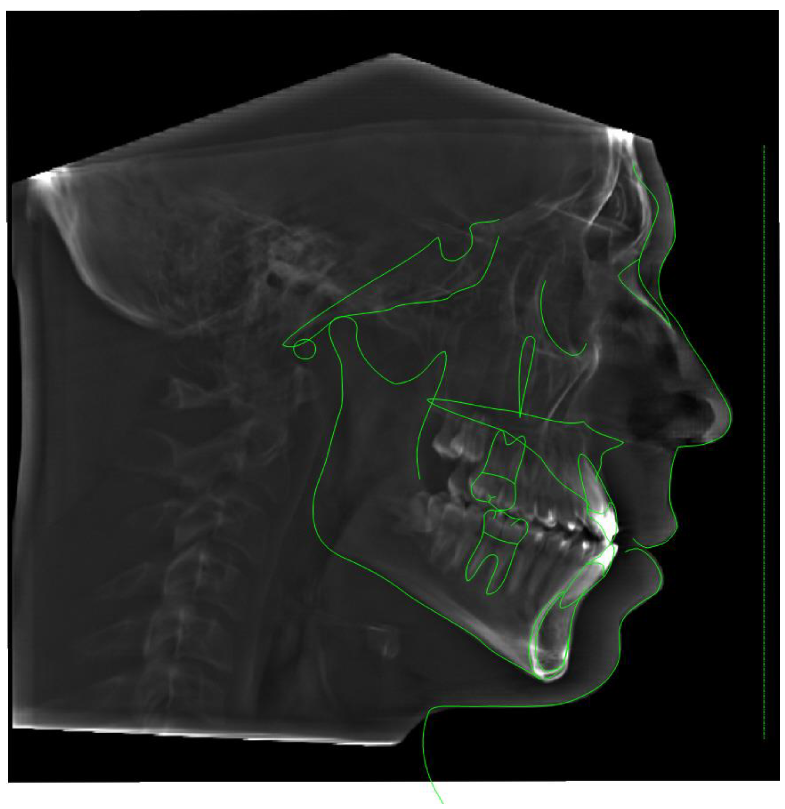
Figure 2.
Coronal view of the nasal base floor at the level of maxillary first molars depicting the location and depth of the piezocorticotomy incision and its relationship to the nasal septum position (white arrow). The 3d guided piezocorticotomy is aimed and planned to locate the incision directly under the septum to ensure symmetrical disarticulation of the midpalatal suture.
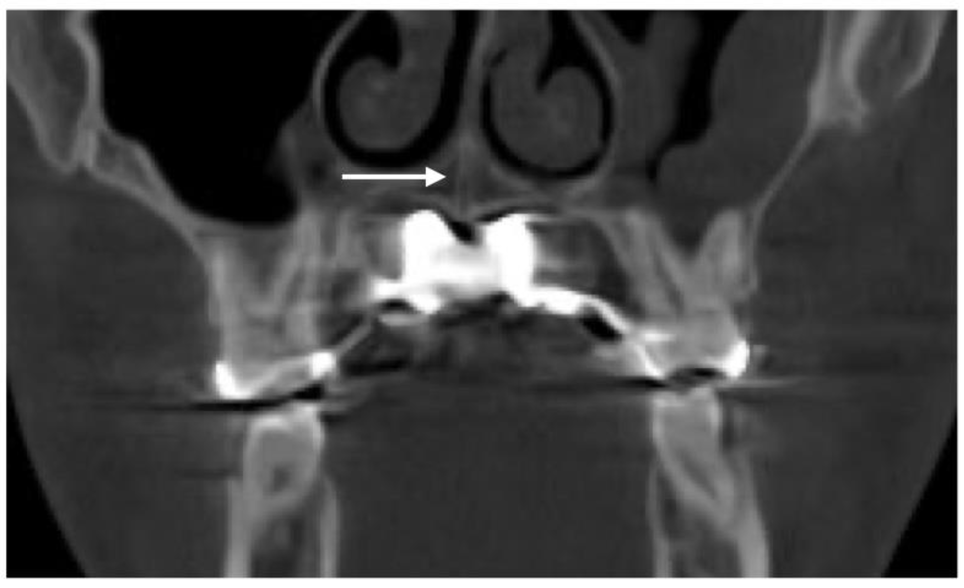
Figure 3.
Pre- (A) and post-expansion (B) view of the custom MARPE appliance with the power screw and framework arms removed after the completion of the expansion, with additional composite bonding on the mesial surfaces of ##8 and 9 for esthetic purposes (B).
Figure 3.
Pre- (A) and post-expansion (B) view of the custom MARPE appliance with the power screw and framework arms removed after the completion of the expansion, with additional composite bonding on the mesial surfaces of ##8 and 9 for esthetic purposes (B).
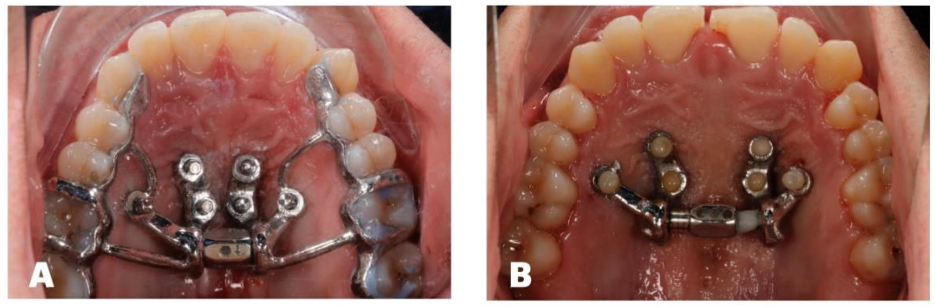
Figure 4.
Disarticulation of the midpalatal suture with parallel separation at the level of the ANS and PNS.
Figure 4.
Disarticulation of the midpalatal suture with parallel separation at the level of the ANS and PNS.
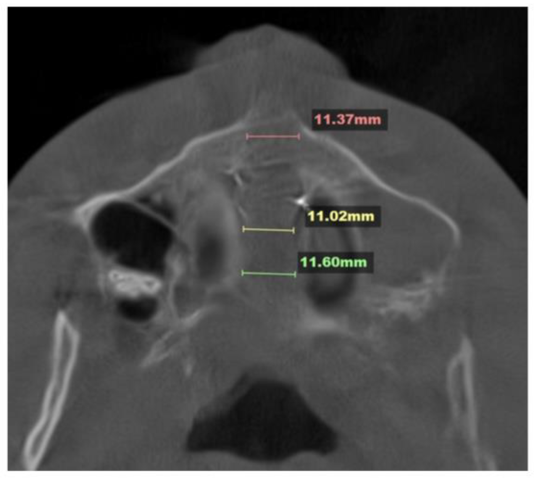
Figure 5.
Inclination of the ANS–PNS plane before (A) and after (B) midfacial expansion, with both volumes oriented relative to the FHP. Inclination of the ANS–PNS is measured relative to the THP.
Figure 5.
Inclination of the ANS–PNS plane before (A) and after (B) midfacial expansion, with both volumes oriented relative to the FHP. Inclination of the ANS–PNS is measured relative to the THP.

Figure 6.
Total vectors of the 3D movements of the facial skeletal structures with 3D-guided midpalatal piezocorticotomy-assisted MARPE.
Figure 6.
Total vectors of the 3D movements of the facial skeletal structures with 3D-guided midpalatal piezocorticotomy-assisted MARPE.
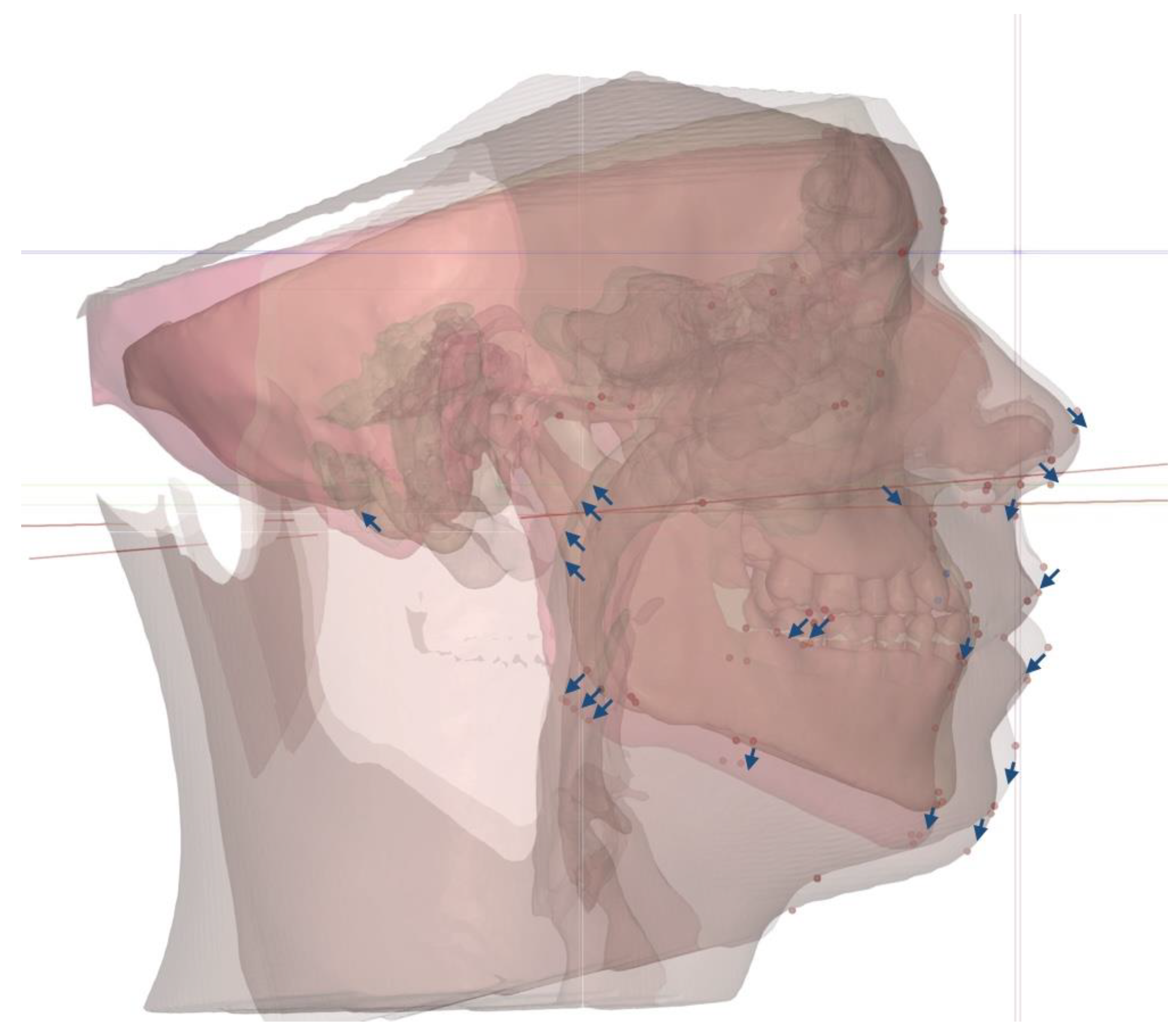
Figure 7.
Before (A) and after (B) expansion orientation of the ANS–PNS plane and maxillary cant plane, showing the distinct rotation of both. Orientation of the ANS–PNS plane revealed the left-side rotation of the plane, with the center of rotation at the PNS; while the maxillary canine plane rotated left side up, with the center of rotation at the midface.

Figure 8.
Total vectors of rotation in the axial plane, with superimposition at the true horizontal plane (THP at Na) and midfacial plane showing the migration of the nasal septum and expansion toward the left lateral nasal wall, the rotation of the maxillary canine plane around the center of rotation at the midface, and the rotation of the ANS–PNS, favoring the left side, with the center of rotation at the PNS.
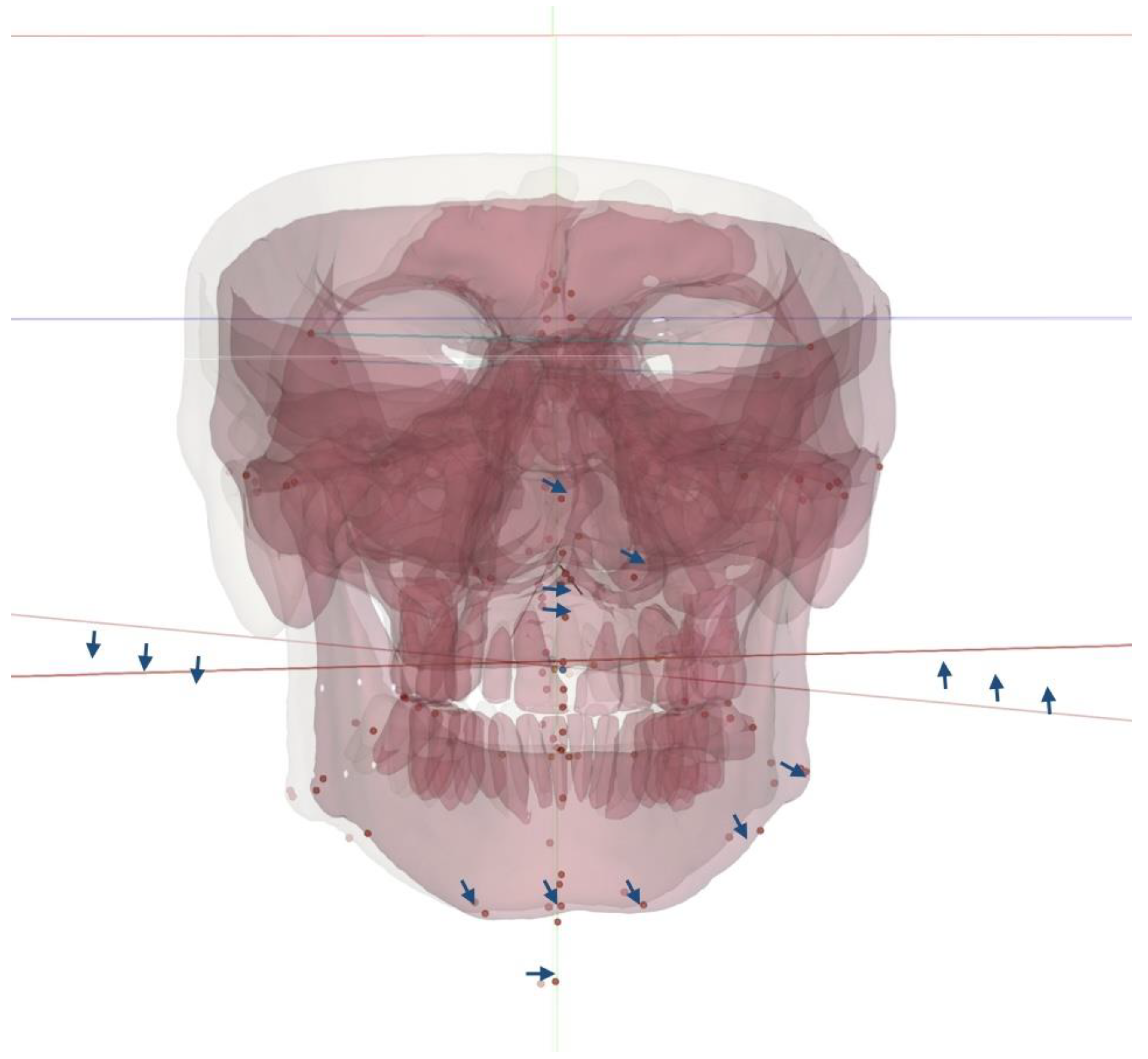
Figure 8.
Size and orientation of the upper airway in the coronal plane: (A) before treatment; (B) after midfacial expansion. Size and orientation of the upper airway in the sagittal plane: (C) inclination of the upper airway with respective cervical lordotic changes; (D) post-expansion cervical curvature improvement with an increase in the total upper airway volume and its minimum cross-section and a reduction in the forward upper airway inclination.

Table 1.
Lateral cephalometric measurements and their values before treatment (Roth–Jarabak analysis, modified).
Table 1.
Lateral cephalometric measurements and their values before treatment (Roth–Jarabak analysis, modified).
| Measurement | Value, degrees |
| SNA | 82 |
| SNB | 83 |
| ANB | -1 |
| U1 to Palatal Plane | 121 |
| IMPA | 98 |
| Gonial Angle (Ar-Go-Me) | 120 |
| Articular Angle (S-Ar-Go) | 123 |
| Saddle Angle (N-S-Ar) | 146 |
Disclaimer/Publisher’s Note: The statements, opinions and data contained in all publications are solely those of the individual author(s) and contributor(s) and not of MDPI and/or the editor(s). MDPI and/or the editor(s) disclaim responsibility for any injury to people or property resulting from any ideas, methods, instructions or products referred to in the content. |
© 2025 by the authors. Licensee MDPI, Basel, Switzerland. This article is an open access article distributed under the terms and conditions of the Creative Commons Attribution (CC BY) license (http://creativecommons.org/licenses/by/4.0/).
Copyright: This open access article is published under a Creative Commons CC BY 4.0 license, which permit the free download, distribution, and reuse, provided that the author and preprint are cited in any reuse.


