
Submitted:
19 September 2025
Posted:
23 September 2025
You are already at the latest version
Abstract
Introduction. Midpalatal suture expansion is effective in both growing and adult patients. Miniscrew-assisted rapid palatal expansion (MARPE) provides greater skeletal effects and fewer dentoalveolar side effects than traditional expanders. However, asymmetric expansion remains a challenge, often influenced by pre-existing craniofacial asymmetries, appliance design, and suture morphology. This case report describes asymmetric expansion using 3D-guided piezocorticotomy-assisted MARPE and its management with direct printed aligners (DPA). Methods. A patient with facial asymmetry, mandibular deviation, narrow maxillary arch, and multiple dentoalveolar deformities underwent pretreatment evaluation, including root inclination analysis and CBCT imaging. A MARPE appliance with 3d guided piezocorticotomy assistance was applied. Post-expansion orthodontic treatment was digitally planned and performed with direct printed aligners. Results. During MARPE activation, asymmetric midpalatal suture disarticulation was observed, with greater displacement on the left side due to jackscrew orientation and root proximity. Post-expansion orthodontic correction with DPAs allowed precise root positioning, redistribution of space, and improved occlusal symmetry. Over 20 months, significant improvements were achieved in midline orientation, axial root inclination, and transverse arch coordination. Conclusion. This case underscores the importance of pretreatment evaluation of asymmetries and careful appliance design in MARPE protocols. It also demonstrates that direct printed aligners, supported by digital planning, can provide accurate and efficient dentoalveolar correction following asymmetric expansion.
Keywords:
MARPE
; guided midpalatal piezocorticotomy
; adults
; asymmetry
; aligners
; direct printed aligners
INTRODUCTION
The literature reports a variety of appliance designs that are included under the definition of mini-screw-assisted rapid palatal expanders (MARPE). Most cohort studies describing the effects of mini-screw-assisted rapid palatal expanders refer to Maxillary Skeletal Expanders (MSEs). [1,2,3] The existing literature has reported that the use of an MSE is associated with significant changes in bone structure surrounding the maxillary complex, including an increase in zygomaticomaxillary width with the center of rotation of the zygomaticomaxillary complex at the proximal point of the zygomatic process of the temporal bone [2].
Maxillary suture disarticulation patterns were described in the review article by Zarate-Guerra et al. [4]. This review concludes that with mini-screw-assisted rapid palatal expansion appliances, the symmetry of perimaxillary suture disarticulation depends on pterygomaxillary suture separation and its degree.
Symmetry of expansion with MARPE and RPE was compared by Barton and coauthors [5] in a study of 180 CBCT scans of 60 growing patients. They concluded that besides greater degree of dento-alveolar effects on molar inclination, both techniques are not associated with any significant asymmetries.
A series of case reports is available showing the efficiency of MARPE in treating pre-existing unilateral and posterior cross-bites, the most wide spread asymmetrical conditions diagnosed during pre-treatment stage. [6,7,8]
Insightful study by ALmaqrami and collegues [9] assessed condylar positional changes following MARPE-assisted treatment of unilateral crossbites in adult patients. Authors concluded that MARPE treatment was associated with the increase in asymmetry of the condylar positions and rotational changes to the condylar head positioning on the affected side. This study is among the first to evaluate mandibular positional response to maxillary width changes with MARPE treatment.
ALmaqrami and colleagues published another clinical trial study evaluating factors associated with asymmetrical expansion through MARPE treatment of adult patients. [10] This study linked the asymmetrical expansion with pre-existing asymmetry of the midpalatal suture. Authors reported 46% incidence of asymmetrical expansion.
Another research group studied frontomaxillary suture and nasomaxillary suture disarticulation effects in adult patients treated with tooth-bone-borne expanders. [11] The incidence of asymmetry in this study was 30% and was primarily associated with the unilateral asymmetric separation of the frontomaxillary suture and pre-existing facial asymmetry.
No studies reported prediction measures of asymmetrical expansion neither specific methods of its correction.
The recently introduced 3D-guided midpalatal piezocorticotomy-assisted MARPE expansion protocol presents significant improvements regarding the predictability of Midfacial Expansion in adult patients and the symmetry of nasal floor separation [12]. Current case report focuses on pre-treatment asymmetry analysis and post-expansion asymmetry management during 3D guided midpalatal piezocorticotomy assisted MARPE expansion with direct printed aligner treatment.
MATERIALS AND METHODS
PRE-TREATMENT RECORDS AND ANALYSIS
A 32 yo female patient presented for the consultation with the chief complaint of correcting her teeth relationships for future restorative work. Pre-treatment analysis was made to ensure comprehensive treatment planning, restoration of functional occlusion with canine guidance, aesthetic positioning of anterior teeth, and symmetrical condylar relationships before proceeding with restorative intervention.
A step-by-step procedure of records analysis is presented below.
Pre-treatment diagnosis
Pre-treatment extra- and intraoral photographs along with the CBCT were analyzed to determine the presence of any pre-existing skeletal, functional, dento-alveolar, and dental asymmetries.
Facial analysis: pre-existing facial asymmetry with the lower third of the face midline (chin alignment) shifted to the left side was noted. Reduced lower third of the face height and retruded profile were distinct features of the pre-treatment facial analysis. (Figure 1 and Figure 2).
Figure 1.
Pre-treatment extra- and intraoral photographs showing facial asymmetry with chin shifted to the left side, mandibular midline shifted 2.5 mm to the left compared to the maxillary dental midline which coincides with the facial midline. Occlusal intraoral photographs show multiple microdentic teeth including peg-shaped ##7, 10, microdentic #13, #20, missing #21, implant crown #4: A- extra-oral view in repose, B- extra-oral view smiling, C - extra-oral profile, D - intra-oral views.
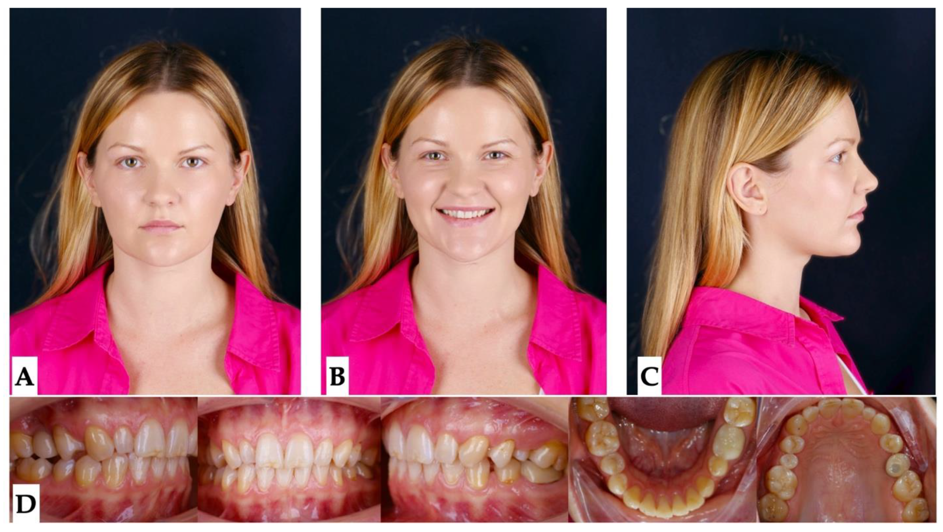
Figure 2.
Pre-treatment extra- oral photographs showing facial asymmetry with chin shifted to the left side (A), and retruded profile (B).
Figure 2.
Pre-treatment extra- oral photographs showing facial asymmetry with chin shifted to the left side (A), and retruded profile (B).
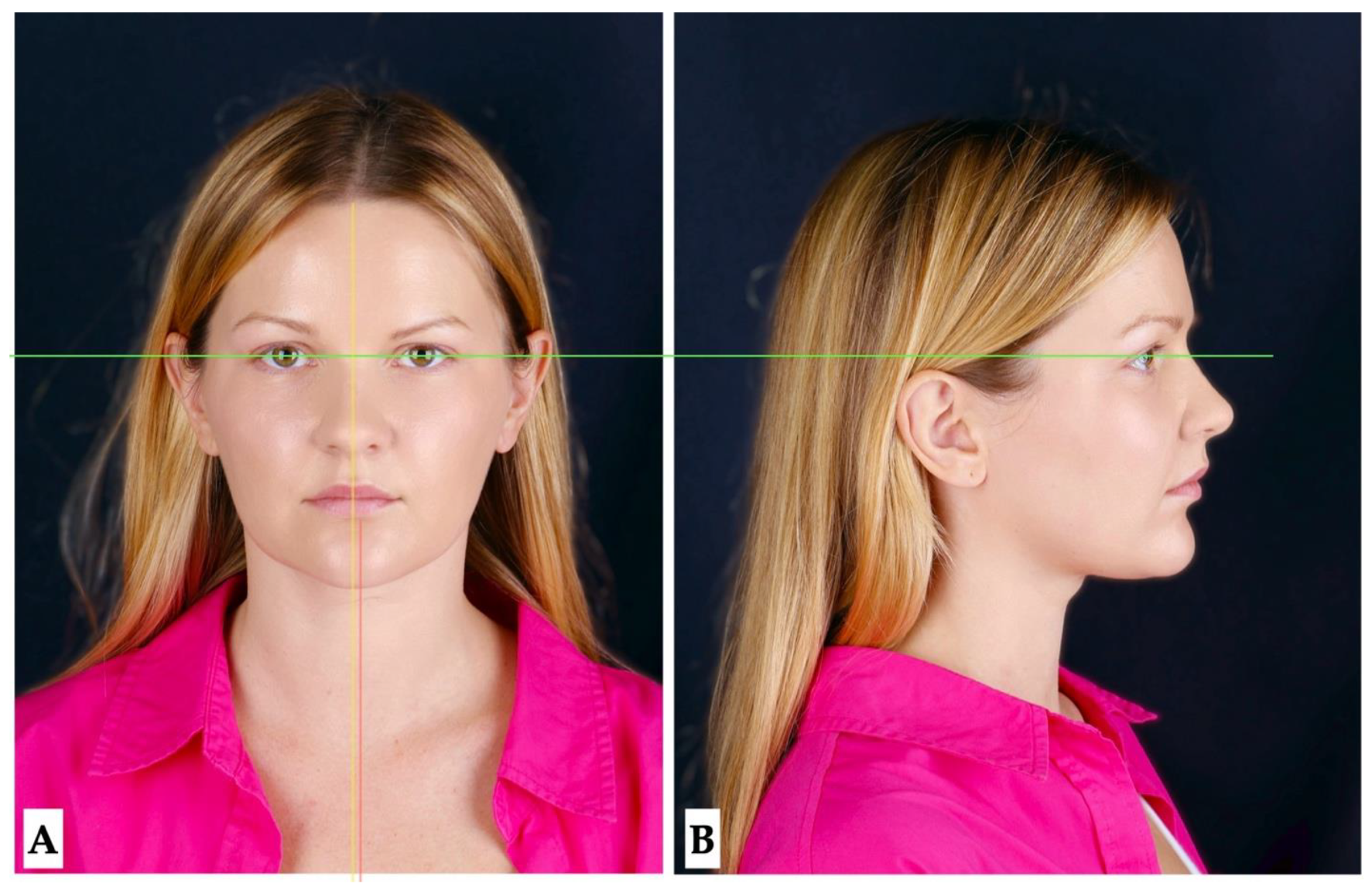
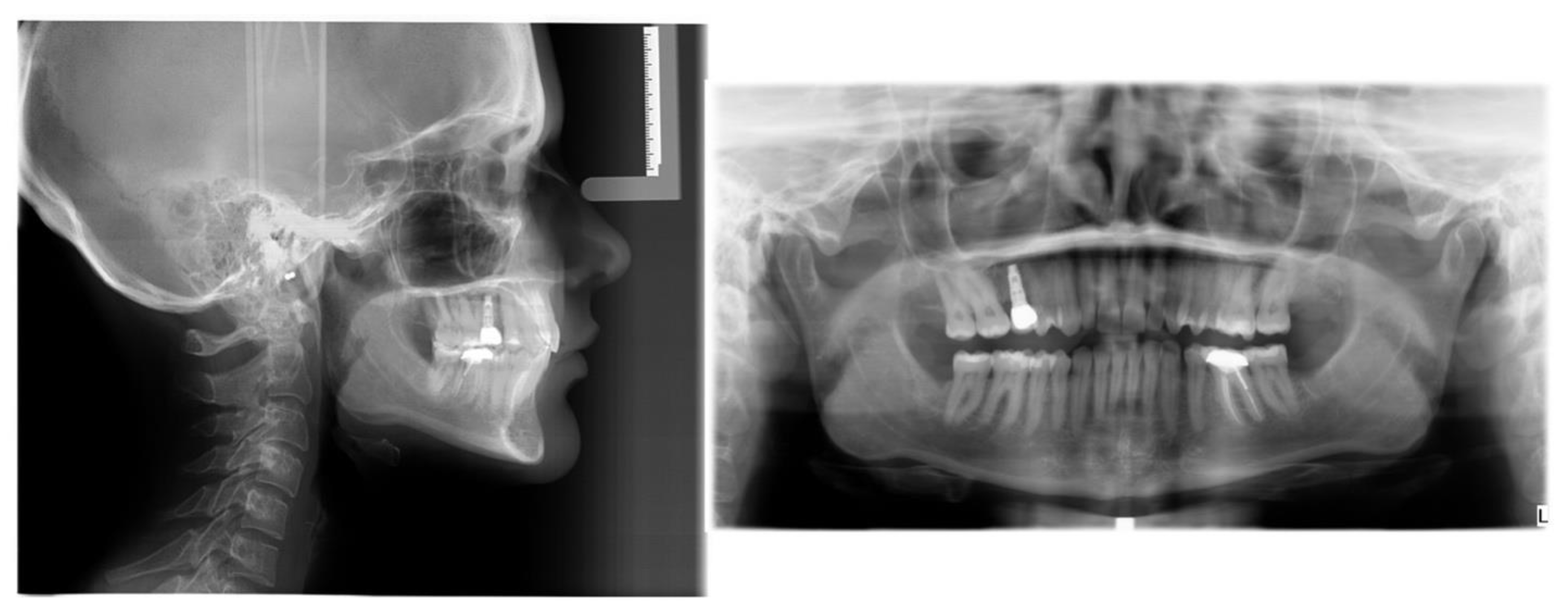
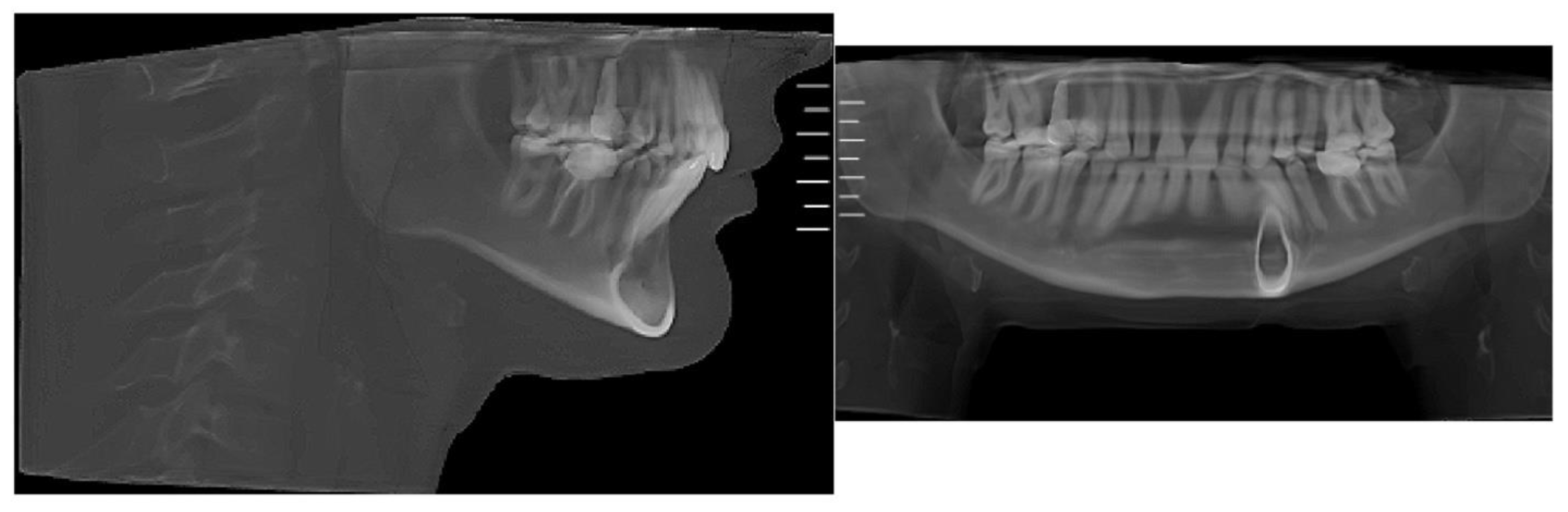
Figure 3.
Pre-treatment lateral cephalometric and panoramic radiographs taken in habitual occlusion.
Figure 3.
Pre-treatment lateral cephalometric and panoramic radiographs taken in habitual occlusion.
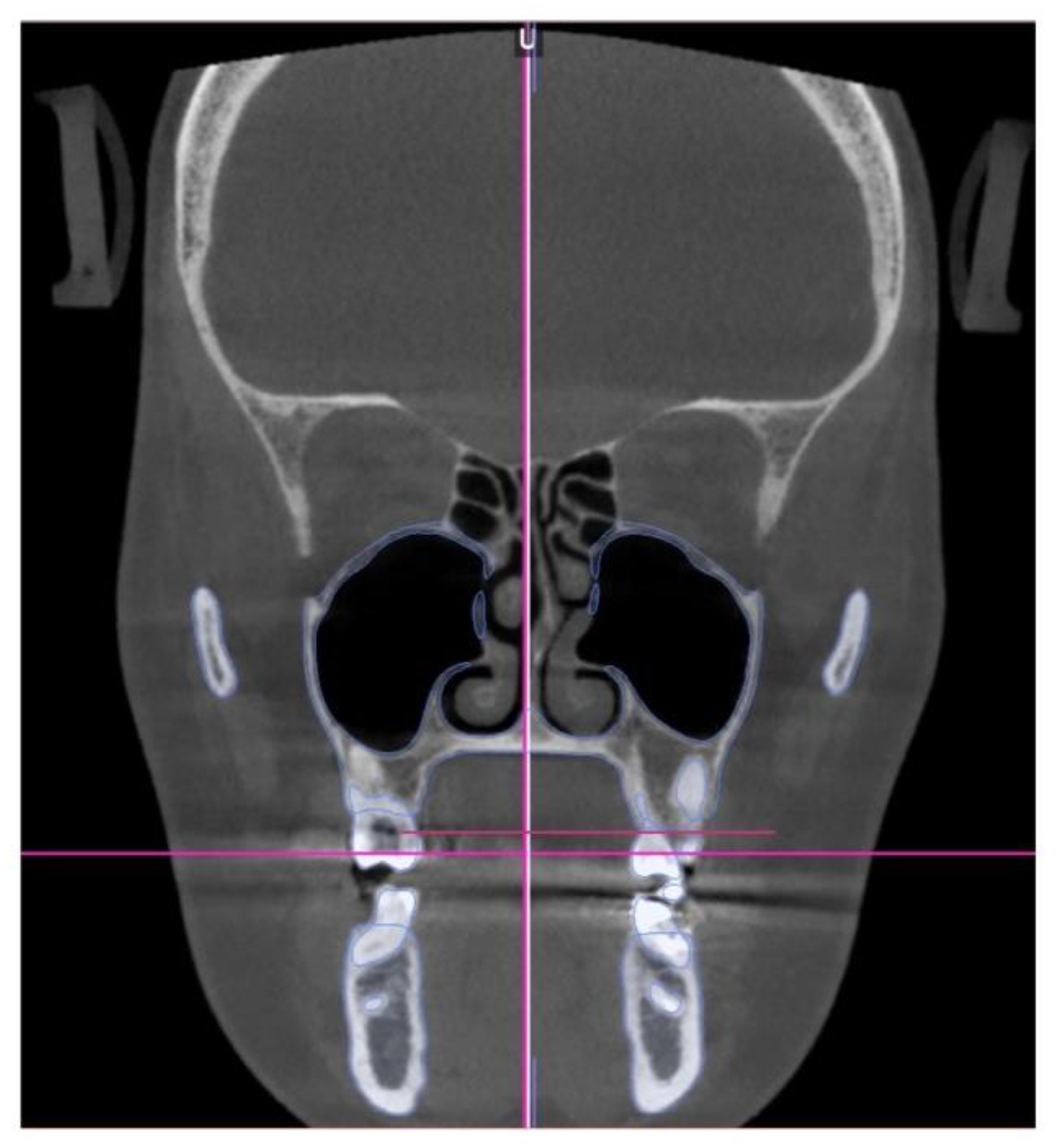
Skeletal analysis:
Orbito-Condylion line was used to orient the maxilla-mandibular complex before and after expansion [13] in sagittal plane, Orbital plane was used for the coronal plane orientation, and ANS-PNS plane was used to orient the pre-treatment maxilla-mandibular complex in axial plane. The limitation of the pre-treatment CBCT record was patient not maintaining habitual occlusion. Due to this limitation only maxillary 3D measurements will be compared. (Figure 4)
Dento-alveolar analysis: dento-alveolar slicing was performed at different levels of the maxillary teeth roots (apical third, half of the root length, and lower third of the root length) to evaluate the symmetry of root positions relative to the buccal cortical plate of the maxillary alveolar process. Upper left quadrant showed clear asymmetry of the root positions with the closer proximity to the buccal cortical plates. (Figure 5 and Figure 6). Palatal plane orientation before treatment is parallel to the constructed Orbital plane as seen on Figure 6, while the maxillary occlusal plane shows definitive canting with the left side occlusal plane located below the right side.
Figure 5.
Pre-treatment axial plane slices visualization: A- axial slice at the level of the ANS with the skull oriented to all three reference planes, this view shows closer proximity of the root arises of the left upper quadrant to the buccal cortical plate of the alveolar process, B - axial view in the same orientation at the level of the 1/2 root length following the same pattern of buccal cortical plate proximity of the UL maxillary roots, C - ANS-PNS and Orbital planes orientation at the level of the lower 1/3 of the root length.
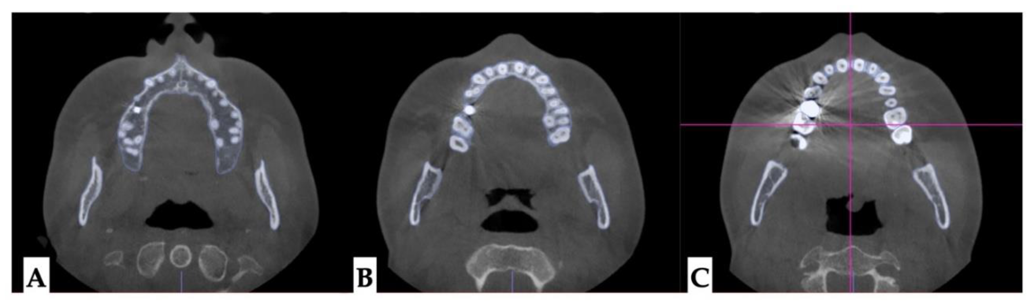
Figure 6.
Pre-treatment axial plane slices visualization: A- axial slice at the level of the ANS with the skull oriented to all three reference planes, this view shows closer proximity of the root arises of the left upper quadrant to the buccal cortical plate of the alveolar process, B- ANS-PNS and Orbital planes orientation at the level of the lower 1/3 of the root length, both views showing asymmetry in UL roots positioning relative to the constructed circle with vertical diameter coinciding with the ANS-PNS plane.
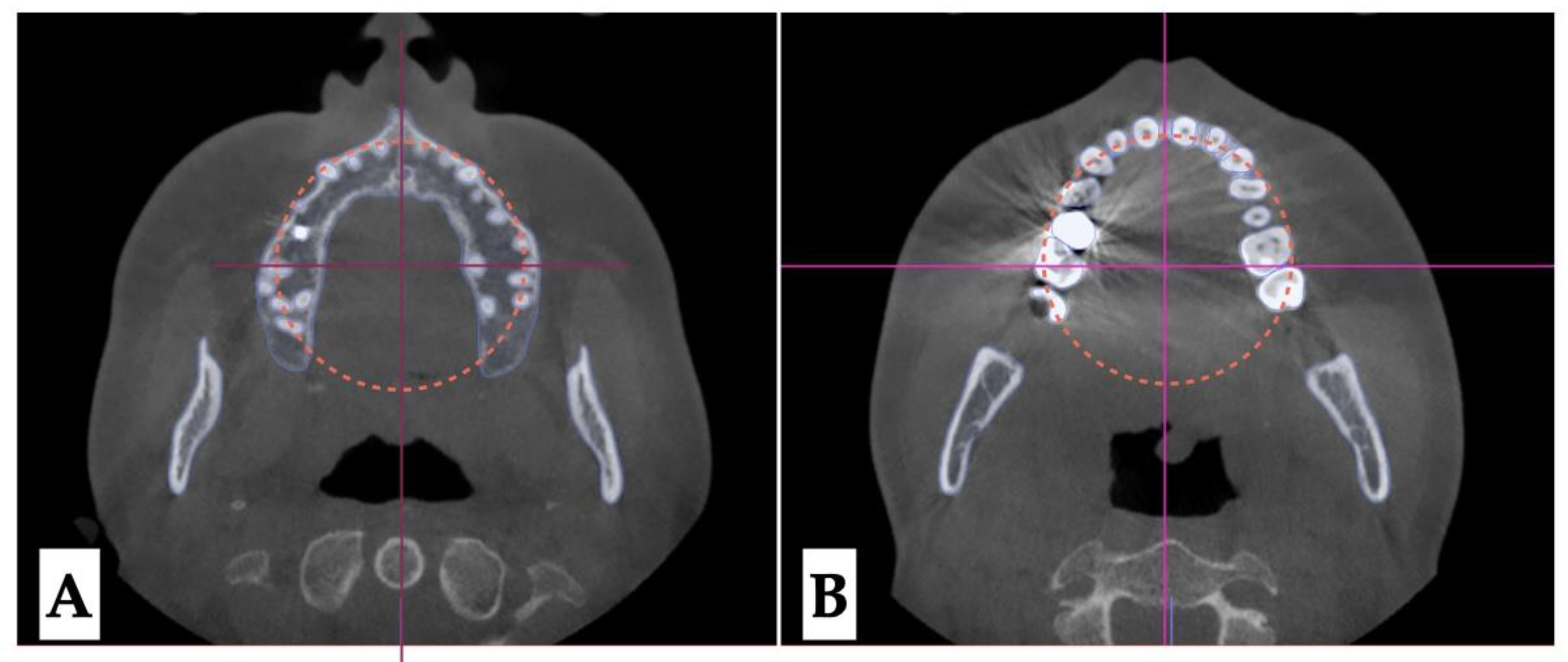
Figure 7.
Pre-treatment coronal plane orientation depicting parallel orientation of the palatal plane relative to the constructed Orbital plane. The vertical dento-alveolar positions of maxillary molars indicate canting of the maxillary occlusal plane. .
Figure 7.
Pre-treatment coronal plane orientation depicting parallel orientation of the palatal plane relative to the constructed Orbital plane. The vertical dento-alveolar positions of maxillary molars indicate canting of the maxillary occlusal plane. .
Dental analysis: Differential inclination of the maxillary incisors is shown in Figure 8.
Lateral cephalometric radiograph and panoramic radiograph immediately after expansion shown in Figure 9.
PROCEDURES AND APPLIANCES
Surgical Protocol All procedures were performed under local anesthesia, initiated with topical application of 20% benzocaine, followed by infiltration of 0.5% bupivacaine (Marcaine) with 1:200,000 epinephrine into the mucosa overlying the midpalatal suture and surrounding tissues.
3D Surgical Guide Design A patient-specific surgical guide was fabricated using Nemocast software (Nemotec, Madrid, Spain). The guide was designed according to the anatomical position of the nasal septum in sagittal, coronal, and axial planes.
Osteotomy Planning and Appliance Design Piezocorticotomy cuts were individually planned for each patient to preserve approximately 10–12 mm of intact midpalatal suture anteriorly near the incisive foramen. The cuts extended posteriorly toward the posterior nasal spine (PNS), enabling midsagittal separation of the palatal processes of the maxilla and the horizontal plates of the palatine bones. Custom 3D printed MARPE appliance was fabricated incorporating 12 mm Powerscrew (Tigerdental, Horbranz, Austria) and 6 anchoring miniscrews (4x1.8x15 mm, 2x1.8x13 mm, Biomaterials Korea, Seoul, Korea).
POSTOPERATIVE ASSESSMENT, ANALYSIS OF OUTCOME, AND ASYMMETRY CORRECTION
Due to the tooth-bone-borne nature of the appliance, its placement is limited by the shape of the hard palate and its outline, the yaw of the palatal (maxillary base) plane, and its relationship to the plane connecting the posterior–superior edges of the pterygomaxillary fissure (Figure 10).
The following series of pre-expansion, expansion, and post-expansion maxillary occlusal views show the progress of 3D-guided piezocorticotomy MARPE expansion. Six mini-screws anchor the MARPE appliance to the bone of the palatal processes of the maxillary bones, with the framework cemented to the maxillary molars, premolars, and canines, including implant crown #4 (Figure 11).
The expansion process lasted for 8 weeks with 1 turn/day, which translates to activation of approximately 0.11 mm/turn. The pattern of midpalatal suture separation was evaluated after the completion of expansion and is shown in Figure 12. The midpalatal suture was completely disarticulated, involving both the ANS and PNS areas. The transverse palatal suture showed signs of disarticulation as well, with the left side having a larger amount of separation.
Post-expansion dentoalveolar movement progression is shown in Figure 13. The initial axial inclinations of maxillary incisors, microdontia with varying cross-sections of the maxillary incisor roots, and the pattern of disarticulation of the transverse suture all contributed to the degree of post-expansion incisor position asymmetry with perceived dominance of the buccal outline of the left maxillary segment compared to the right side. The dentoalveolar tooth positions, along with the differential initial root inclinations, were progressively corrected with directly printed aligner orthodontic movements (Thera-Hartz TA-28, Graphy, Seoul, Korea). Post-alignment axial inclinations of the maxillary incisors are shown in Figure 14.
Figure 15 shows the directly printed aligners during the pre-restorative stages of treatment.
Figure 15.
Directly printed aligners (Thera-Harz, TA-28 resin, Graphy, Seoul, Korea) in post-expansion stage.
Figure 15.
Directly printed aligners (Thera-Harz, TA-28 resin, Graphy, Seoul, Korea) in post-expansion stage.
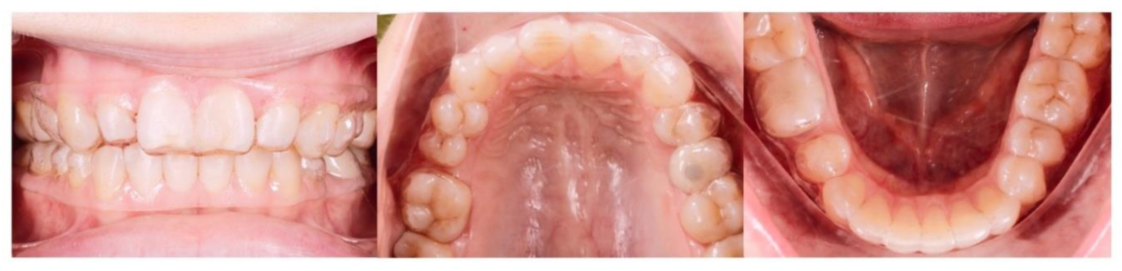
Figure 16.
A - Pre-expansion orientation and width of the mid palatal, and transverse suture; B - immediately post-expansion orientation and disarticulation of the mid palatal and transverse sutures with greater degree of disarticulation of the left transverse suture; C - midpalatal, transverse suture ossification with minimum-to-no-degree of asymmetry 12 months after completion of expansion.
Pre-restorative records
Figure 17.
Post-treatment extra- and intraoral photographs showing facial symmetry, coinciding facial, maxillary, and mandibular midlines. Occlusal intraoral photographs show multiple microdentic teeth including peg-shaped ##7, 10, microdentic #13, #20, missing #21 and space re-opened for the implant crown #21, implant crown #4, and extra space for restoration of microdentic teeth: A- extra-oral view in repose, B- extra-oral view smiling, C - extra-oral profile, D - intra-oral views.
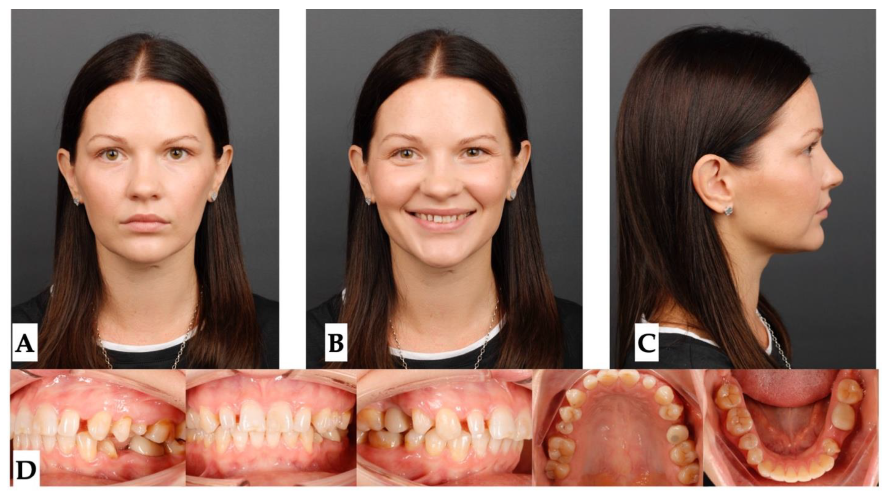
Figure 18.
Pre-restorative lateral cephalometric and panoramic radiographs taken in habitual occlusion.
Figure 18.
Pre-restorative lateral cephalometric and panoramic radiographs taken in habitual occlusion.
DISCUSSION
Multiple studies have shown efficacy of midpalatal suture separation with both Rapid Palatal Expander (RPE) and MARPE expanders in growing individuals emphasizing greater stability during consolidation stage, and lesser bending effects on alveolar processes with MARPE expansion. [14,15]. Other studies show successful applications of MARPE expansion in adult patients emphasizing careful planning for the success of midpalatal suture disarticulation [16] and appliance design and activation planning regarding to the maxillary center of resistance that can control maxillary rotation during expansion. [17]
Current case study describes an occurrence of the asymmetric expansion with 3D guided midpalatal piezocorticotomy assisted MARPE expansion and its management with post-expansion orthodontic movements with direct printed aligners . Post-expansion orthodontic treatment lacks descriptive studies and is limited to case reports. Bud and colleagues described side effects of the MARPE expansion with and without corticopuncture [18] and reported occlusal modifications that occur post-expansion that are related to asymmetrical occlusal relationships prior to the beginning of treatment.
Present study focuses on pre-treatment diagnosis and evaluation for the presence of pre-existing asymmetries and analysis of the asymmetric expansion outcome. As seen from the initial evaluation, patient presented with facial asymmetry related to both mandibular asymmetric position and narrow upper arch due to multiple dento-alveolar deformations and microdentic teeth. Initial root orientation was evaluated as a part of staged analysis, and revealed differential root inclination of the maxillary incisors relative to the buccal cortical plate of the maxillary alveolar process. Root proximity and higher buccal root torque of all maxillary incisors with left incisors being in closer proximity compared to the right side was one of the predisposing factors to pre-existing asymmetry of the maxillary anterior alveolar process in axial plane.
As Almagrami and coauthors have previously pointed out [10], midpalatal suture asymmetry was one of the factors most frequently associated with asymmetrical MARPE expansion. As stated in the case report by Choi and coauthors [17], appliance design can influence force vectors applied during maxillary skeletal expansion with MARPE appliance.
Expansion outcome of the current case shows asymmetry in transverse suture separation that was related to the orientation of the screw relative to the course of the transverse suture and midpalatal suture. Further attachment of the jackscrew on the left side has caused greater lever arm for the rotation of the palatal process of the left maxillary bone with its partial forward displacement. This was further accompanied by the proximity of the incisor roots of the left maxillary anterior alveolar process and resulted in perceived antero-posterior discrepancy between the maxillary alveolar process on both sides of the disarticulated midpalatal suture.
Post-expansion dento-alveolar correction was performed using direct printed aligners (DPA). The efficacy of the DPA has been shown in multiple studies [19,20,21], which describe their higher accuracy, precision, efficacy, and shape-memory effects along with higher degree of root control due to thermoelasticity of the Thera-Hartz resin and appliance design incorporating longer margins. DPAs with shape-memory effects were used for post-expansion orthodontic treatment in both cases to facilitate and improve the quality of orthodontic tooth movements post-expansion. NemoCast (Nemotec, Madrid, Spain) planning software was used to plan orthodontic tooth movements and allow precise positioning of the roots by merging intraoral scans and CBCTs. Aligners were 3D printed using Graphy Thera-Harz TA-28 resin and compatible 3D printers.
Significant improvement in midline orientation, axial root inclination, space re-distribution was achieved over the course of 20 months post-expansion.
4. Conclusions
This case study highlights the efficacy and challenges of MARPE expansion, particularly when asymmetry occurs due to factors such as midpalatal suture orientation, root proximity, and appliance design. The patient presented with pre-existing facial and dental asymmetries that contributed to uneven transverse expansion, with greater displacement on the left side. Post-expansion correction using direct printed aligners (DPA) allowed precise root control and effective redistribution of space, supported by digital planning tools. Over 20 months, treatment achieved significant improvements in midline orientation, root inclination, and overall symmetry..
5. Patents
US and Canada Patent Pending: Piezocorticotomy guide for midpalatal skeletal expansion (Application # 18/919,416).
Author Contributions
Conceptualization, S.K. and V.K.; methodology, S.K. and V.K.; software, S.K.; validation, D.C. and S.K.; formal analysis, V.K. and S.K.; investigation, S.K.; resources, S.K.; data curation, D.C. and S.K.; writing—original draft preparation, S.K.; writing—review and editing, S.K. and V.K.; visualization, D.C.; supervision, S.K.; project administration, S.K. All authors have read and agreed to the published version of the manuscript.
Funding
This research received no external funding.
Institutional Review Board Statement
Ethical review and approval were waived for this study due to its retrospective nature and the exclusive use of fully de-identified data.
Informed Consent Statement
All patients provided informed consent for the use of their de-identified data prior to treatment.
Data Availability Statement
The original contributions presented in this study are included in the article. Further inquiries can be directed to the corresponding author.
Conflicts of Interest
The authors report there are no competing interests to declare.
Abbreviations
The following abbreviations are used in this manuscript:
| MARPE | Mini-Screw-Assisted Rapid Palatal Expansion |
| ANS | Anterior Nasal Spine |
| PNS | Posterior Nasal Spine |
| DPA | Directly Printed Aligners |
| CBCT | Cone-Beam Computer Tomography |
| MSE | Maxillary Skeletal Expander |
References
- D. P. Brunetto, C. E. Moschik, R. Dominguez-Mompell, E. Jaria, E. F. Sant’Anna, and W. Moon, “Mini-implant assisted rapid palatal expansion (MARPE) effects on adult obstructive sleep apnea (OSA) and quality of life: a multi-center prospective controlled trial,” Prog. Orthod., vol. 23, no. 1, p. 3, Feb. 2022. [CrossRef]
- D. Cantarella et al., “Zygomaticomaxillary modifications in the horizontal plane induced by micro-implant-supported skeletal expander, analyzed with CBCT images,” Prog. Orthod., vol. 19, no. 1, p. 41, Oct. 2018. [CrossRef]
- D. Cantarella et al., “Digital Planning and Manufacturing of Maxillary Skeletal Expander for Patients with Thin Palatal Bone,” Med. Devices Auckl. NZ, vol. 14, pp. 299–311, 2021. [CrossRef]
- D. C. Zárate-Guerra and G. Gutiérrez-Tapia, “[Structural changes in the craniofacial complex induced by microimplant-supported skeletal expander - MSE. a review],” Rev. Cient. Odontol. Univ. Cient. Sur, vol. 13, no. 2, p. e243, 2025. [CrossRef]
- B. Barton et al., “Long-term assessment of skeletal and dental asymmetry after conventional and mini-implant-assisted rapid palatal expansion,” Am. J. Orthod. Dentofac. Orthop. Off. Publ. Am. Assoc. Orthod. Its Const. Soc. Am. Board Orthod., vol. 167, no. 4, pp. 399-408.e1, Apr. 2025. [CrossRef]
- Y. Fan et al., “Successful treatment for an adult with bilateral posterior teeth crossbite by miniscrew-assisted rapid palatal expansion: A case report,” Clin. Case Rep., vol. 12, no. 8, p. e9216, Aug. 2024. [CrossRef]
- M. H. Büyükçavuş, E. Albayrak, and Y. Findik, “Miniscrew-assisted Rapid Palatal Expansion Before Orthognathic Surgery for a Patient With Laterognathia,” J. Craniofac. Surg., vol. 36, no. 3, pp. e237–e241, May 2025. [CrossRef]
- T. Takagi and E. Tanaka, “An adult case of unilateral posterior crossbite caused by maxillary transverse deficiency treated with miniscrew-assisted rapid palatal expansion,” J. Stomatol. Oral Maxillofac. Surg., vol. 124, no. 6, p. 101443, Dec. 2023. [CrossRef]
- B. S. ALmaqrami et al., “Condylar changes in adult patients with unilateral posterior crossbite following microimplant-assisted rapid palatal expansion: A retrospective CBCT study,” J. Stomatol. Oral Maxillofac. Surg., vol. 126, no. 4S, p. 102205, Sept. 2025. [CrossRef]
- B. S. Almaqrami, M. S. Alhammadi, M. A. A. Al-Somairi, E. S. ALyafrusee, H. Xiong, and H. He, “Three-dimensional assessment of asymmetric mid-palatal suture expansion assisted by a customized microimplant-supported rapid palatal expander in non-growing patients: Uncontrolled Clinical Trial,” Orthod. Craniofac. Res., vol. 25, no. 2, pp. 234–242, May 2022. [CrossRef]
- K.-A. Kim, S.-H. Oh, B.-H. Kim, and S.-J. Kim, “Asymmetric nasomaxillary expansion induced by tooth-bone-borne expander producing differential craniofacial changes,” Orthod. Craniofac. Res., vol. 22, no. 4, pp. 296–303, Nov. 2019. [CrossRef]
- S. Koval, V. Kolesnyk, and D. Chepanova, “Applications of the Novel Midpalatal Piezocorticotomy Guide for MARPE Midfacial Skeletal Expansion,” J. Clin. Med., vol. 14, no. 13, p. 4728, July 2025. [CrossRef]
- H. K. Vedavathi, P. Roy, P. K. P. Shashanka, and S. Kyathanahalli Subbaiah, “Orbito-Condylion and Orbito-Basion Lines as Alternatives to Frankfurt and Sella- Nasion Lines in Cephalometry,” Iran. J. Orthod., vol. 17, no. 1, pp. 1–6, June 2022. [CrossRef]
- J.-H. Chun et al., “Skeletal and alveolar changes in conventional rapid palatal expansion (RPE) and miniscrew-assisted RPE (MARPE): a prospective randomized clinical trial using low-dose CBCT,” BMC Oral Health, vol. 22, no. 1, p. 114, Apr. 2022. [CrossRef]
- S. Mehta, S. A. Arqub, M. Vishwanath, M. Upadhyay, and S. Yadav, “Biomechanics of conventional and miniscrew-assisted rapid palatal expansion,” J. World Fed. Orthod., vol. 13, no. 3, pp. 105–112, June 2024. [CrossRef]
- C. Carlson, J. Sung, R. W. McComb, A. W. Machado, and W. Moon, “Microimplant-assisted rapid palatal expansion appliance to orthopedically correct transverse maxillary deficiency in an adult,” Am. J. Orthod. Dentofac. Orthop. Off. Publ. Am. Assoc. Orthod. Its Const. Soc. Am. Board Orthod., vol. 149, no. 5, pp. 716–728, May 2016. [CrossRef]
- S.-H. Choi, J. Y. Jeon, K.-J. Lee, and C.-J. Hwang, “Clinical applications of miniscrews that broaden the scope of non-surgical orthodontic treatment,” Orthod. Craniofac. Res., vol. 24 Suppl 1, pp. 48–58, Mar. 2021. [CrossRef]
- E. S. Bud et al., “Observational Study Regarding Possible Side Effects of Miniscrew-Assisted Rapid Palatal Expander (MARPE) with or without the Use of Corticopuncture Therapy,” Biology, vol. 10, no. 3, p. 187, Mar. 2021. [CrossRef]
- T. Torkomian, F. de la Iglesia, and A. Puigdollers, “3D-printed clear aligners: An emerging alternative to the conventional thermoformed aligners? - A systematic review,” J. Dent., vol. 155, p. 105616, Apr. 202. [CrossRef]
- B. Ludwig, K. Ojima, J. Q. Schmid, V. Knode, and R. Nanda, “Direct-printed aligners: A clinical status report,” J. Clin. Orthod. JCO, vol. 58, no. 11, pp. 658–668, Nov. 2024.
- S. Y. Lee et al., “Thermo-mechanical properties of 3D printed photocurable shape memory resin for clear aligners,” Sci. Rep., vol. 12, no. 1, p. 6246, Apr. 2022. [CrossRef]
Figure 4.
Pre-treatment CBCT volume orientation in three planes of space. A, B- orientation in sagittal plane with Orbito-Condylion plane as a reference, C - axial plane orientation with ANS-PNS plane as a reference, and D - coronal plane orientation with Orbital plane as a reference line.
Figure 4.
Pre-treatment CBCT volume orientation in three planes of space. A, B- orientation in sagittal plane with Orbito-Condylion plane as a reference, C - axial plane orientation with ANS-PNS plane as a reference, and D - coronal plane orientation with Orbital plane as a reference line.
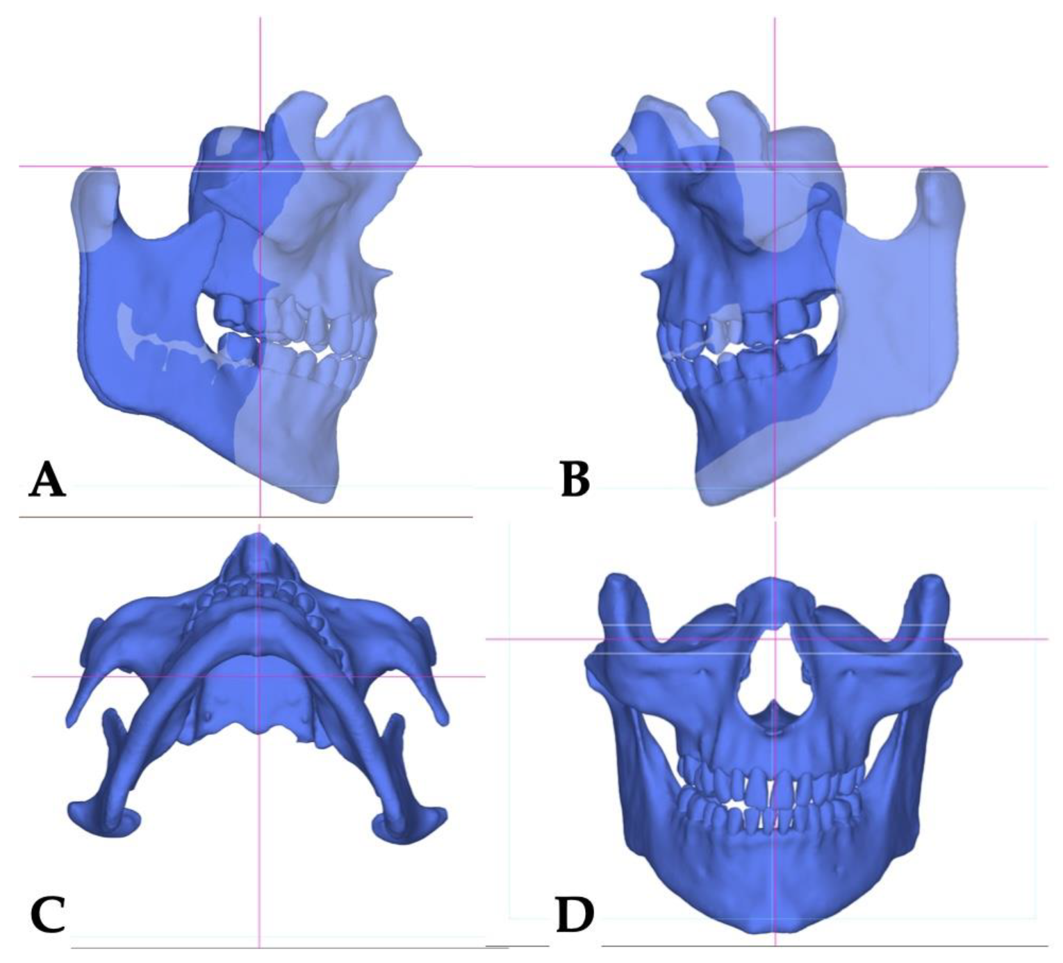
Figure 8.
The sagittal view of the axial cross-section of maxillary incisors: A—Maxillary right lateral incisor; B—maxillary right central incisor; C—maxillary left central incisor; D—maxillary left lateral incisor. The axial inclination of the maxillary left incisors is steeper compared to the right side.
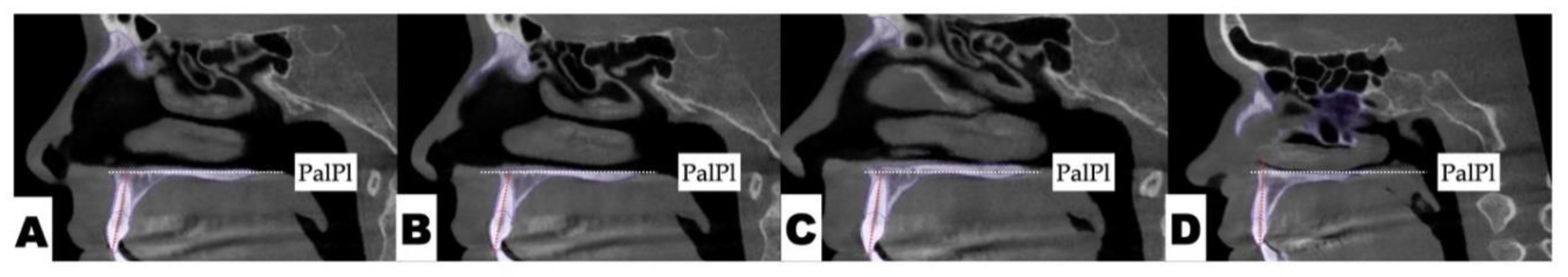
Figure 9.
Post-expansion lateral cephalometric and panoramic radiographs taken in habitual occlusion.
Figure 9.
Post-expansion lateral cephalometric and panoramic radiographs taken in habitual occlusion.
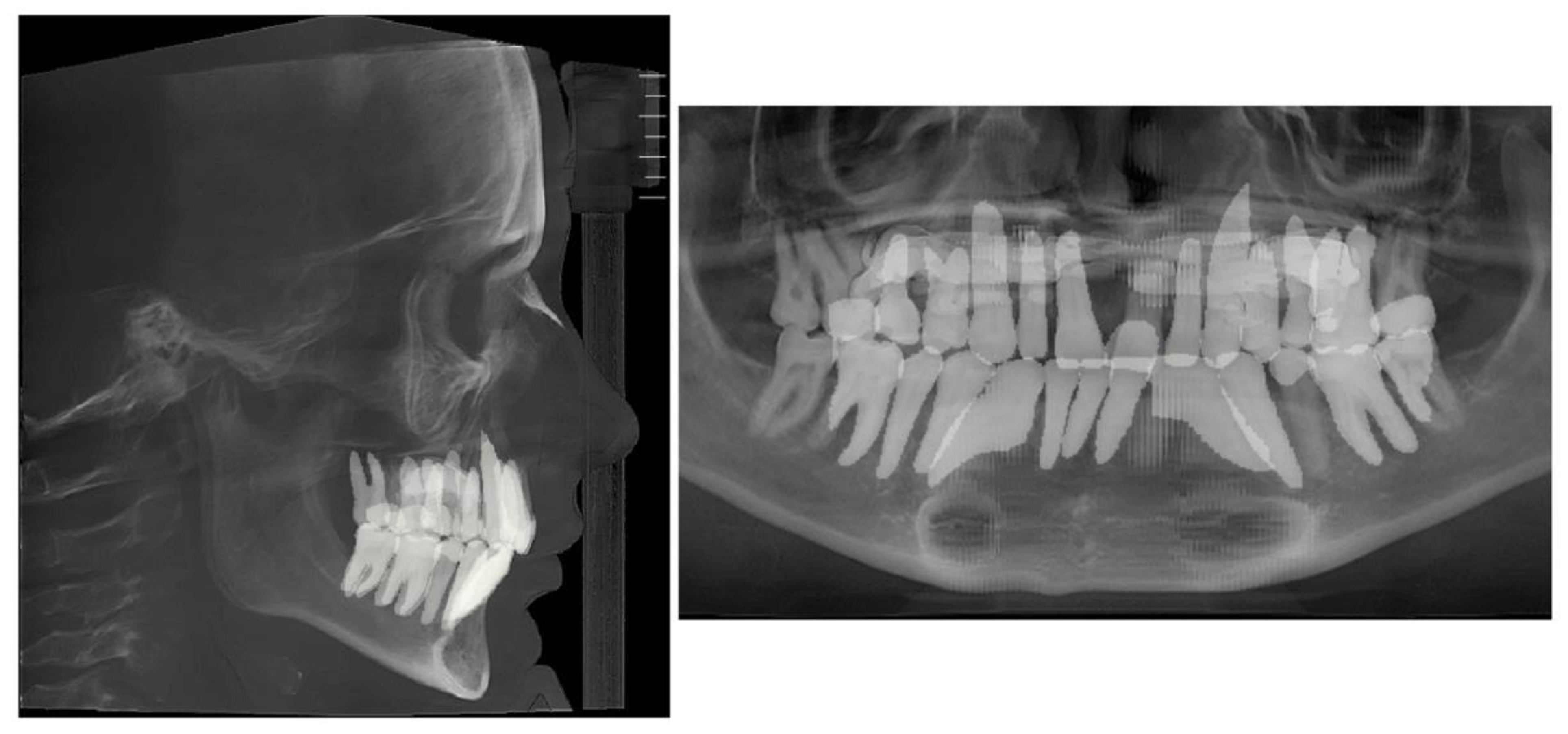
Figure 10.
The initial inclination (yaw) of the maxillary base at the level of the posterior wall of the maxillary sinuses and the inferior orbital fissure. Ort—Orbit; IOF—Inferior Orbital Fissure; MxS—Maxillary Sinus; NS—Nasal Septum; NB—Nasal Base.
Figure 10.
The initial inclination (yaw) of the maxillary base at the level of the posterior wall of the maxillary sinuses and the inferior orbital fissure. Ort—Orbit; IOF—Inferior Orbital Fissure; MxS—Maxillary Sinus; NS—Nasal Septum; NB—Nasal Base.
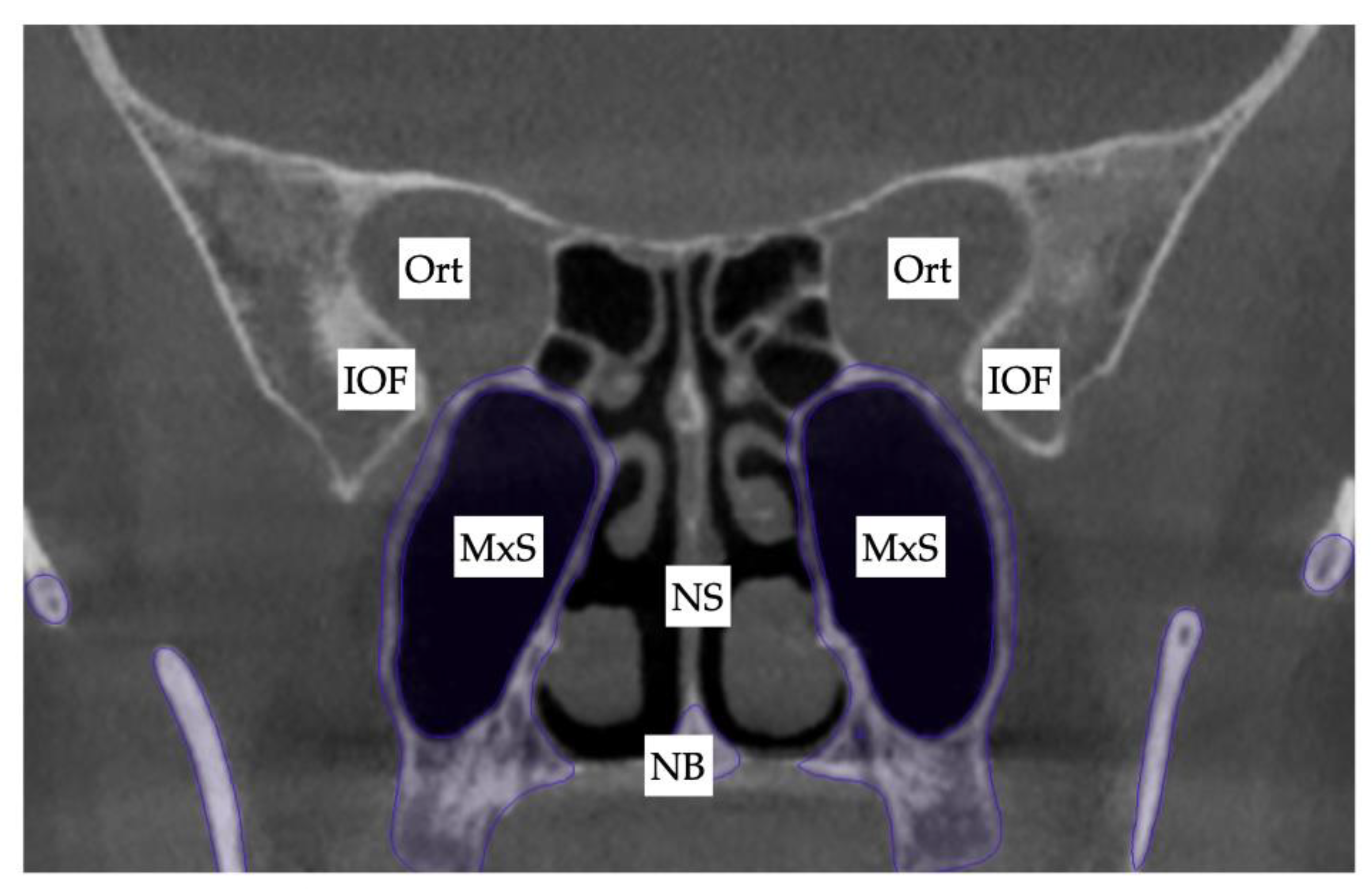
Figure 11.
Process of 3D-guided midpalatal piezocorticotomy-assisted MARPE expansion. A, D—Pre-expansion occlusal and frontal views; B, E—4 weeks of expansion after 3D-guided midpalatal piezocorticotomy-assisted MARPE expansion, activation 1 turn/day (0.11 mm/turn); C, F—post-expansion progress prior to initiation of aligner space closure and alignment.
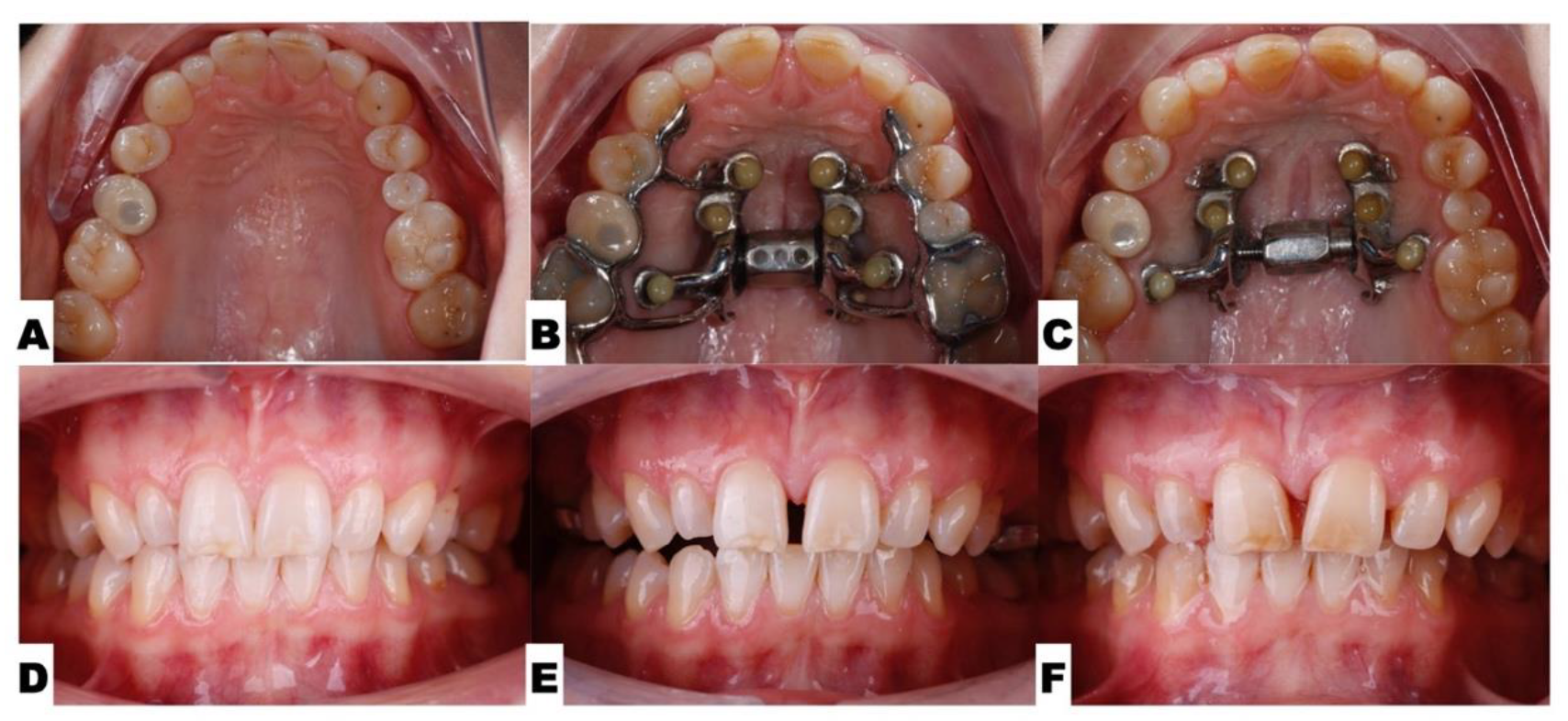
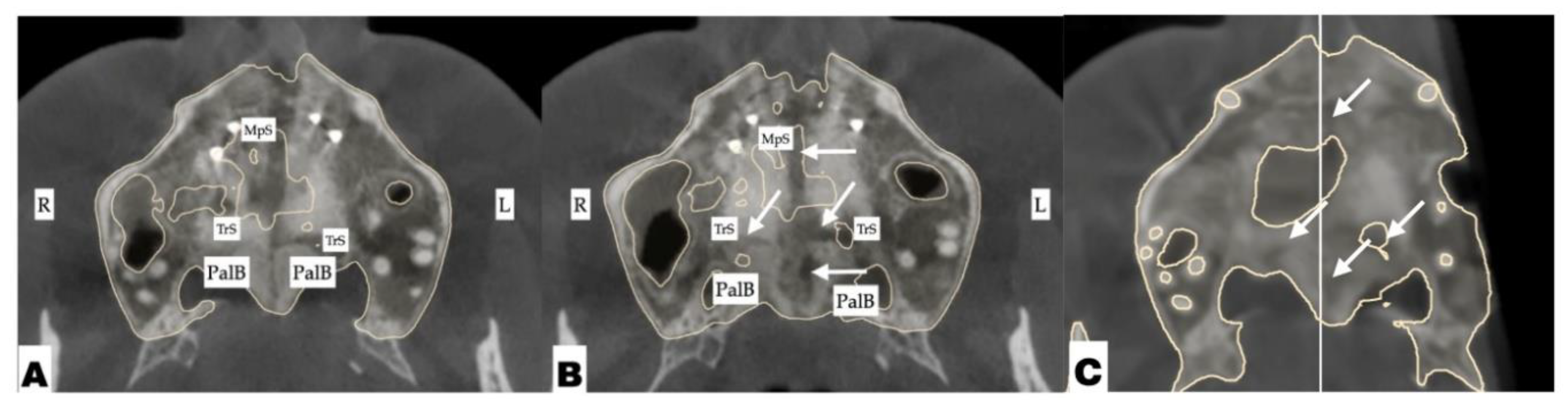
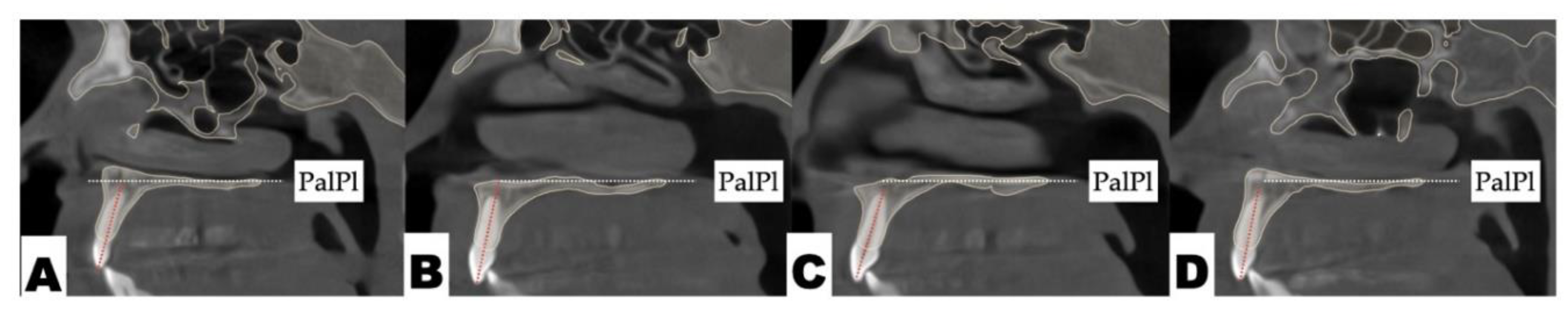
Figure 12.
Disarticulation of the midpalatal and transverse sutures with 3D-guided midpalatal piezocorticotomy-assisted MARPE expansion. Both axial slices show the disarticulation of the transverse suture with a greater degree of separation on the left side. Arrows point to areas of disarticulation. R—Right side; L—left side; MpS—midpalatal suture; TrS—transverse suture; PalB—palatine bone.
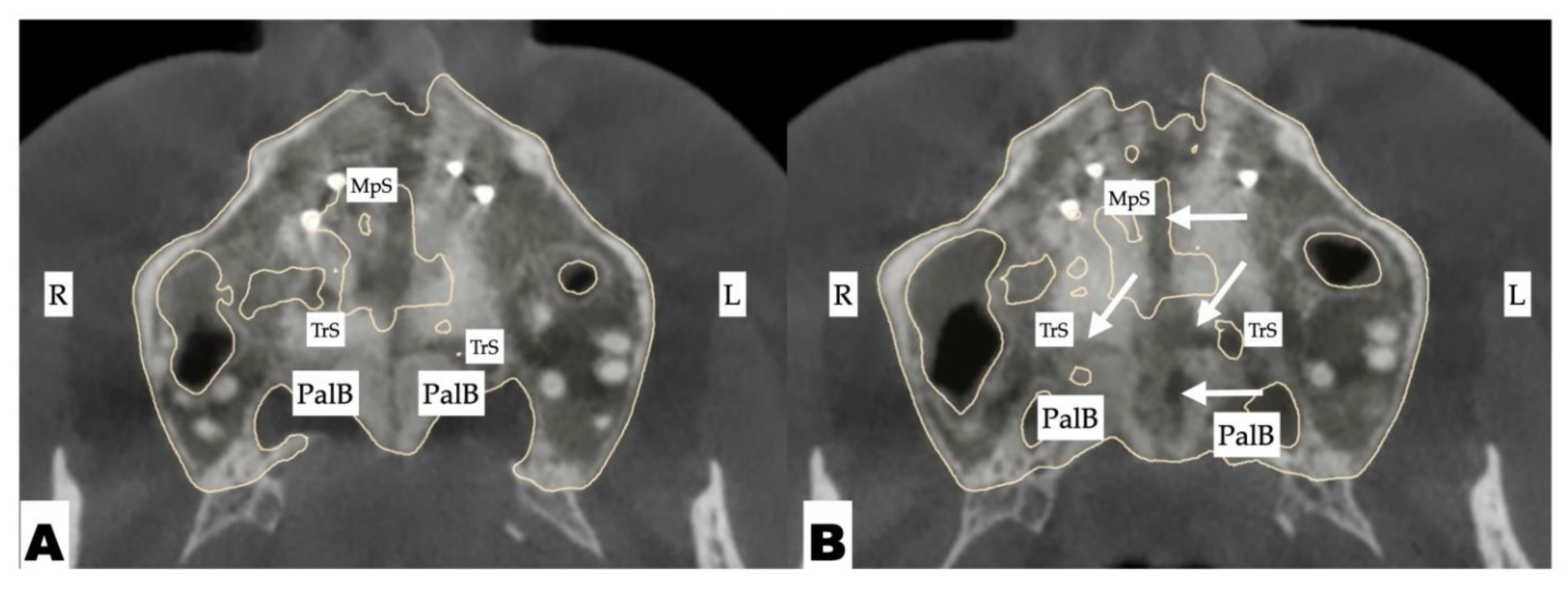
Figure 13.
The progression of post-expansion aligner dentoalveolar movements with redistribution of teeth along the dentoalveolar process for further restorative treatment for microdontia. A—Pre-expansion; B—immediately after completion of 3D-guided midpalatal piezocorticotomy-assisted MARPE expansion; C—distalization of the left posterior teeth initiated with space opening for restorative treatment of lateral incisors and second maxillary left premolar; D-F—progression of direct aligner-assisted tooth movements for premolar de-rotation, molar distalization, and axial inclination correction for maxillary incisors with alignment of incisal edges due to complex root torque movements.
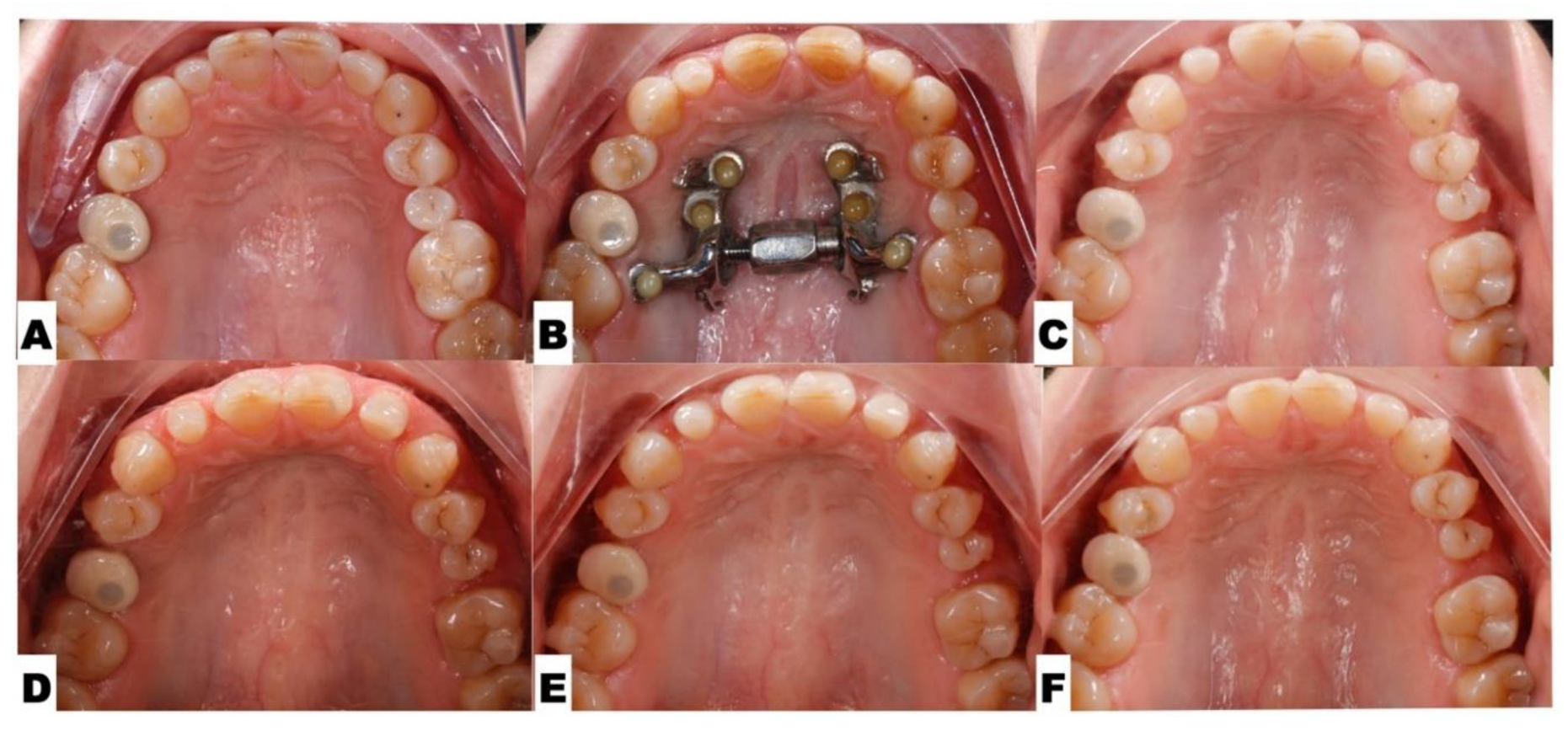
Figure 14.
The sagittal view of the axial cross-section of maxillary incisors after aligner axis correction: A—maxillary right lateral incisor; B—maxillary right central incisor; C—maxillary left central incisor; D—maxillary left lateral incisor. The axial inclination of all maxillary incisors has improved, with a significant reduction in buccal root torque of the maxillary left central and lateral incisors with directly printed aligner orthodontic movements.
Disclaimer/Publisher’s Note: The statements, opinions and data contained in all publications are solely those of the individual author(s) and contributor(s) and not of MDPI and/or the editor(s). MDPI and/or the editor(s) disclaim responsibility for any injury to people or property resulting from any ideas, methods, instructions or products referred to in the content. |
© 2025 by the authors. Licensee MDPI, Basel, Switzerland. This article is an open access article distributed under the terms and conditions of the Creative Commons Attribution (CC BY) license (http://creativecommons.org/licenses/by/4.0/).
Copyright: This open access article is published under a Creative Commons CC BY 4.0 license, which permit the free download, distribution, and reuse, provided that the author and preprint are cited in any reuse.


