Submitted:
11 September 2025
Posted:
12 September 2025
You are already at the latest version
Abstract
The impact of a molten droplet on a solid surface, forming a “splat,” is a fundamental phenomenon observed across numerous industrial surface engineering techniques. For example, thermal spray deposition is widely used to create metal, ceramic, polymer, and composite coatings that are vital for aerospace, biomedical, electronics, and energy applications. Significant progress has been made in understanding droplet impact behavior, largely driven by advancements in high-resolution and high-speed imaging techniques, as well as computational resources. Although droplet impact dynamics, splat morphology, and interfacial bonding mechanisms have been extensively reviewed, a comprehensive overview of the mechanical behaviors of single splats, which are crucial for coating performance, has not been reported. This review bridges that gap by offering an in-depth analysis of bonding strength and residual stress in single splats. The various experimental techniques used to characterize these properties are thoroughly discussed, and a detailed review of the analytical models and numerical simulations developed to predict and understand residual stress evolution is provided. Notably, the complex interplay between bonding strength and residual stress is then discussed, examining how these two critical mechanical attributes are interrelated and mutually influence each other. Subsequently, effective strategies for improving interfacial bonding are explored, and key factors that influence residual stress are identified. Furthermore, the fundamental roles of splat flattening and formation dynamics in determining the final mechanical properties are critically examined, highlighting the challenges in integrating fluid dynamics with mechanical analysis. Thermal spraying serves as the primary context, but other relevant applications are briefly considered. Cold spray splats are excluded because of their distinct bonding and stress generation mechanisms. Finally, promising future research directions are outlined to advance the understanding and control of the mechanical properties in single splats, ultimately supporting the development of more robust and reliable coating technologies.
Keywords:
splat deposition
; thermal spray
; bonding strength
; residual stress
; individual particle
1. Introduction
1.1. Background
The impact of droplets on solid surfaces is a fundamental phenomenon with broad relevance across numerous industrial and scientific domains. Specifically, in processes like thermal spraying, molten or semi-molten particles impact a substrate and undergo rapid solidification, leading to the formation of pancake-shaped structures known as “splats” [1]. Each splat serves as the foundational building block for creating a protective or functional layer. These splats, composed of metals [2], ceramics [3], polymers [4], or composites [5], are widely used in aerospace components [6], biomedical implants [7], electronics [8], and energy systems [9].
Among the industrial deposition techniques, thermal spraying, which encompasses plasma spraying [10], flame spraying [11], and high-velocity oxy-fuel spraying [12], is particularly advantageous owing to its low cost and the ease of depositing thick coatings using a wide range of materials. Distinct from cold spray processes [13,14], where bonding is predominantly achieved through plastic deformation without particle preheating, thermal spraying involves rapid melting and solidification. This unique characteristic gives rise to distinct interfacial bonding phenomena and complex stress evolution that critically affect overall coating performance. Despite the extensive literature on droplet impact dynamics, the mechanical behaviors at the single splat scale, specifically those concerning interfacial bonding strength and residual stress, remain relatively underexplored.
Given the significant influence of drop impact phenomena, previous reviews have comprehensively addressed various factors associated with this complex process. These include the intrinsic aspects of fluid flow [15,16,17], the dynamics of splat solidification [18,19], the distribution of impact forces and stresses [20], and the broader mechanics of splat formation [1,21,22,23,24] and interfacial bonding [25]. Furthermore, reviews have delved into specific applications, such as spray cooling [26], water droplet freezing [27], heterogeneous droplet behavior [28], interactions with hot walls [29], superhydrophobic surfaces [30], and the behavior of complex fluids [31].
These works provide invaluable insights into fluid dynamics and solidification, but they often neglect the subsequent mechanical behavior of individual splats. Moreover, they rarely detail how bonding strength is formed, measured, and influenced by process parameters, and they do not extensively cover how residual stresses evolve and contribute to critical issues like delamination, cracking, and eventual coating failure. This research gap underscores a critical disconnect between the initial fluid dynamics and solidification of splats and the ultimate performance of coatings. Coating performance, particularly its durability and integrity, is fundamentally governed by the mechanical properties derived during deposition and solidification. This gap hinders the rational design of thermal spray processes for specific application requirements because the links between process parameters (fluid dynamics) and final coating reliability (mechanical properties) have not been fully elucidated. This review directly addresses these issues and bridges the gap by uniquely focusing on the mechanical consequences of splat formation, especially the fundamental aspects of bonding mechanisms and residual stress development.
1.2. Interfacial Bonding and Residual Stress of Single Splats
Generally, three primary mechanisms contribute to splat adhesion: physical bonding, mechanical interlocking, and chemical bonding [3]. Physical bonds, often referred to as Van der Waals forces, represent a relatively weak form of interfacial connection [32]. In contrast, mechanical interlocking and chemical bonding are considerably more robust and are the principal targets for enhancing interfacial bonding strength. Chemical bonding is particularly difficult to achieve in thermal spraying, primarily owing to the rapid solidification rates and inherently limited diffusion time [33]. The bonding characteristics of single splats are typically assessed by evaluating their tensile and shear strength, which correspond to the mode I (opening) and mode II (sliding) fractures, respectively. Although several experimental methods have been developed to quantify the bonding strength of single splats over the past couple decades, directly measuring this strength remains a significant challenge.
Residual stress in deposited splats originates from three main phenomena, namely high-velocity impact, rapid cooling contraction, and thermal mismatch, which induce peening stress, quenching stress, and thermal stress, respectively. Peening stress, inherently compressive, results from plastic deformation and serves as the dominant contributor to the residual stress in cold spraying [13]. Quenching stress, conversely, develops as the splat cools from its stress-free temperature to the substrate’s temperature [34]. Thermal stress subsequently emerges during the further cooling of both the splat and the substrate down to ambient temperatures, and the tensile or compressive character depends on the thermal mismatch between splats and substrates. Several factors contribute to the relaxation of these residual stresses, including microcracking, viscous deformation, interfacial defects, and interfacial sliding [34]. Despite ongoing efforts, developing a precise numerical or theoretical model for predicting residual stress in single splats remains a significant challenge.
Furthermore, residual stress affects bonding strength measurements [35,36,37], yet the exact mathematical correlation and underlying mechanisms between these two properties remain largely unknown, warranting further investigation. It is important to note an asymmetry in the current research landscape regarding these two properties. The experimental characterization of interfacial bonding strength has been widely reported in previous studies, whereas the theoretical and numerical analyses are comparatively limited. In contrast, for residual stress, analytical models and numerical simulations aimed at elucidating its complex generation mechanisms and enabling prediction have been actively pursued.
The mechanical behaviors of deposited splats, encompassing both bonding strength and residual stress, are intrinsically influenced by the flattening and solidification processes. These processes, in turn, are dictated by the deposition conditions, such as the particle’s initial temperature, impact velocity, and the substrate’s preheating temperature [38,39,40]. To fully comprehend the stress generation and bonding mechanisms, it is necessary to clarify the fundamental splat formation mechanisms and their subsequent effects on mechanical properties. The transient solidification that occurs immediately after impact plays a pivotal role, directly influencing the subsequent stress generation process, and thus remains a major focus within drop impact studies.
1.3. Structure of This Review
This review is structured to provide a comprehensive analysis of the mechanical properties of single splats. The remainder of the paper is organized as follows:
Section 2 offers a comprehensive overview of the experimental methods specifically designed for evaluating the bonding strength of individual splats, considering both direct and indirect testing techniques.
Section 3 discusses the experimental approaches used to characterize residual stress at the splat level, including methods like curvature measurement, nano-indentation, and advanced microscopy.
Section 4 covers the analytical and numerical models developed for calculating and predicting residual stresses.
Section 5 delves into the complex interrelationship between bonding strength and residual stress, exploring strategies for improving interfacial bonding and identifying key factors that influence residual stress. The fundamental role of splat dynamics in determining these mechanical properties is also discussed.
Finally, Section 6 summarizes the main findings and provides insights into future research directions within this specialized field.
2. Characterization of the Bonding Strength in Single Splats
This section thoroughly reviews the various experimental techniques employed to quantify the bonding strength of individual splats, discussing their principles, applications, and limitations.
Splat–substrate adhesion is fundamentally governed by the dynamics and thermodynamics of splat formation. Key factors influencing the adhesion mechanism include substrate temperature, the kinetic energy of in-flight particles, and surface roughness [41,42,43,44,45,46]. Commonly employed approaches for evaluating the interfacial adhesion strength of thermal spray coatings include the scratch test [47], tensile test [48], indentation test [49], three-point bend test [50], and scraping test [51]. However, because of their microscale features and irregular geometry, fewer methods and results have been published regarding the bonding strength of individual deposited splats. Table 1 provides a summary of the experimental techniques reported in the literature for measuring the bonding strength of single splats. The details of each method are reviewed in the following subsections.
2.1. Tensile Test
The tensile bonding strength of a paraffin wax splat deposited on polymer substrates was examined using a simple pull-off method [52]. In this study, a molten wax drop, 3.1 mm in diameter, was released from heights of 20–50 mm onto porous polyethylene and Teflon substrates. The components of the testing system are shown in Figure 1(a-d), where a cylinder was used to bond the splat surface with a structural epoxy. Pores with diameters of 35 or 70 μm were introduced in the substrate to examine the effect of surface penetration, and the bonding strength was evaluated using an analytical model:
Here, Ar and Ac represent the cross-sectional area of the splat material within the holes and the contact area between the splat and the substrate, respectively. The experimentally determined σ and ε values denote the tensile strength of the splat and the adhesive force per unit area, respectively. The reliability of this equation was verified by comparing the calculated results with the experimental results. As shown in Figure 1(e), the measured maximum forces were comparable to the predicted forces for both pore sizes across various droplet release heights.
2.2. Scraping Test
The scraping test is another method used to measure interfacial shear strength [53,54,55,56,57]. Kang et al. used a cutting blade coupled with a load cell to push a paraffin wax splat away from the substrate along the splat/substrate interface. The force evolution was recorded as a function of the blade’s moving distance [56]. The results are shown in Figure 2(a-d), illustrating the effects of various splat deposition conditions, including (a) substrate temperature (Tsub), (b) free-fall height (H), which relates to impact velocity, and droplet temperature (Tdrop) with (c) low and (d) high residual stress in the splats. Bonding strength was quantified using the parameter K(d):
where K(d) is calculated from the real-time scraping force (F(d)), splat thickness (t(d)), and scraping breadth (b(d)) as a function of scraping displacement (d). Both b(d) and t(d) are determined from splat profiles and displacement-force curves. In this work, the splat diameter was approximately 10 mm. The value of K(d) at the maximum scraping force (Fmax), consistently achieved at a scraping displacement between 2 and 7 mm, was defined as K0 to evaluate the interfacial adhesion strength. Fmax and the calculated K0 for each deposition condition are plotted in Figure 2(e-h). The results indicate that interfacial bonding strength was significantly influenced by the deposition conditions, with superior adhesion achieved at higher substrate preheating temperatures, greater drop heights, and higher droplet temperatures. The scraping test results were compared with residual stress-induced interfacial debonding and numerically calculated stress distributions along the interface. The scraping test findings were mutually consistent with the numerical results and observed debonding phenomena.
A more recent study employed a scraping method to measure the micro-shear strength of a ceramic splat deposited on a metal substrate at supersonic or subsonic velocities, investigating the effect of splat morphology [57]. This study revealed that the mechanical/metallurgical interlocking of submicron/nano-columnar grains and restructured amorphous phases enhanced the micro-adhesive properties of needle-shaped splats. For splashing splats, the adhesive force in the central region was observed to be twice as high as that in the peripheral region, primarily attributed to the formation of an air film [58].
2.3. Indentation Test
The indentation method was employed by Balić et al. to investigate the bonding strength of single splats (Figure 3) [59]. The strain energy release rate of alumina (Al2O3) splats deposited on stainless steel 304 was characterized by directly observing interfacial crack propagation during indentation:
Here, ν represents the splat’s Poisson’s ratio, t is the splat thickness, and E is the splat’s elastic modulus. σ0 is the indentation stress, calculated as the compressive stress induced in the section above the prospective crack, reflecting the response to deformation caused by the indentation volume:
where a is half the length of a prospective interfacial crack. V0 is the indentation volume in the splat, derivable from the indenter tip geometry and indentation depth. Crack length was determined by measuring the radial distance from the indentation axis to the edge of the splat that first exhibited debonding. Consequently, G can be re-expressed by substituting Eq. (4) into Eq. (3):
The calculated G values were within a reasonable range of previously reported values for similar bi-material combinations, specifically the interfacial fracture energy of oxide/metal (Al2O3/Au) interfaces [60]. A significant limitation preventing the widespread application of this method is the need to simultaneously perform the test and scanning electron microscopy (SEM) to capture in-situ images during indentation for accurate crack length determination.
2.4. Focused Ion Beam-Milled Microcantilever Beam Bending Test
Fanicchia et al. carried out beam bending tests on focused ion beam (FIB)-milled microcantilevers to investigate the local adhesion distribution within a single splat [61]. Fracture strength was probed at various locations along the splat/substrate interface using an in-situ SEM indenter. Figure 4(a) presents an SEM micrograph of a cantilever milled within the polycrystalline zone of a single splat. As shown in the inset, electron backscatter diffraction (EBSD) mapping confirmed the polycrystallinity of the solidified structure. Applying the linear elastic bending theory for clamped beams, as proposed by Matoy et al. [62], the maximum bending stress at the substrate/splat interface can be calculated:
where F represents the applied load, l is the bending length, and w and t denote the cantilever beam’s width and thickness, respectively.
Based on the solidification zone where each cantilever was milled, three distinct load-displacement behaviors were observed (Figure 4(b)). Within the epitaxial area (black curve), an initial linear elastic region was followed by plastic deformation, evidenced by slip lines at the cantilever base. No interface crack propagation was observed in any specimens tested from this region, as confirmed by the absence of load drops in their curves. Considering the lack of a critical load (Fc) for the direct application of Eq. (6), an adhoc value was determined at 95% of the curve’s slope in the linear elastic region. This method, therefore, provided an underestimation of the precise adhesion strength.
Conversely, a load drop, indicative of interfacial crack initiation, was observed within the polycrystalline zone outside the epitaxial area (blue curve). In these cases, Fc was defined as the load drop value. For cantilevers located in the polycrystalline zone at the splat rim (red curve), no load was recorded, suggesting that very low adhesion was present before indentation. Figure 4(c) illustrates the calculated fracture strength as a function of the normalized splat radius for all tested cantilevers across different solidification zones. Linear fits within each zone are also presented, along with the norm of the residuals. Strength increased from the splat center toward the edge within the epitaxial zone, likely influenced by impact pressure and temperature effects. Conversely, a decrease in fracture strength was observed within the polycrystalline area characterized by small grain sizes (blue). This reduced adhesion, relative to the epitaxial zone and diminishing toward the outer rim, is attributed to lower splat–substrate interdiffusion and edge curling stress relaxation.
2.5. Scratch Test
The scratch test is a widely adopted method for assessing the shear strength at the splat/substrate interface. Sabiruddin and Bandyopadhyay performed some of the first scratch tests on single splats [63]. In their work, Al2O3 splats deposited on Ni–5wt.%Al and Ni–20wt.%Cr bond coats were subjected to scratching using a Rockwell C-type conical diamond indenter with a radius of 200 µm, at speeds of 0.1 or 0.2 mm/s. A fixed normal load, ranging from 1 to 6 N, was applied during scratching, and images of the scratched splats were used to evaluate scratch resistance. Figure 5(a) provides a schematic representation of this scratch testing procedure. Scratch resistance increased with splat thickness and decreased with the presence of a semi-molten phase, which acted as a defect. Furthermore, the extent of splat damage intensified with the increasing scratching speed and normal load.
In the same year, a similar scratch method was employed to measure the adhesion strength of plasma-sprayed carbon nanotube (CNT)-reinforced Al2O3) splats on a steel substrate, aimed at verifying the impact of CNT addition on the adhesion strength of a single splat [64]. As depicted in Figure 5(b), the lateral force was recorded as a function of scratch distance. The adhesion force was then estimated by subtracting the lateral force on the bare steel substrate from the peak force observed during splat delamination. The splat’s adhesion strength was subsequently calculated as the ratio of the adhesion force to the splat area. CNTs significantly enhanced the adhesion strength of a single Al2O3 splat on steel substrates through two primary mechanisms of mechanical bonding: improved splat wettability due to the higher thermal conductivity and specific heat of CNTs, and enhanced mechanical interlocking caused by the anchoring effect of CNTs. Similar findings were reported by Jambagi et al. [65].
The effects of adding hybrid CNTs and graphene nanoplatelets (GNPs) on the bond strength of Al2O3 splats was further investigated using nano-scratch tests [66]. The adhesion strength for pure Al2O3 was measured at 0.21 ± 0.11 MPa, which increased to 1.08 ± 0.38 MPa following the synergistic incorporation of CNTs and GNPs into the Al2O3 matrix. This improvement was primarily attributed to the nanofillers’ high strength, enhanced melting of splats post-reinforcement, and superior interlocking between splats and substrates. It was also noted that as these property-improved splats accumulate to form a thicker coating, the bulk coating properties tend to exhibit comparable characteristics to individual splats.
Chen et al. investigated the detailed debonding process during a micro-scratch test of plasma-sprayed Fe-based splats [67]. As illustrated by the splat debonding mechanism depicted in Figure 6(a), upon contact with the splat, the forces acting on the indenter are defined by:
where Fn and Fτ are the normal and lateral forces on the indenter, Fnsub and Fτsub are the normal and lateral forces exerted by the substrate on the indenter, and Fnspl and Fτspl are the normal and lateral forces exerted by individual splats on the indenter, respectively. The lateral force, penetration depth, and acoustic emission were recorded with respect to the scratch distance, as shown in Figure 6(b-d) for various substrate temperatures. Three distinct stages were observed during the dislodging process. The adhesion strength of a splat is calculated as the ratio between the adhesion force and the bonding area of the splat:
where P is the adhesion strength of a splat, S is the debonding area of the splat, and Fmax is the maximum lateral force during the debonding process. Fact is the actual lateral resistance of the substrate on the indenter when the splat was debonded, which can be obtained by:
where A is the contact radius between the indenter and the substrate, R is the indenter tip radius, h is the penetration depth of the indenter into the substrate when the splat is dislodged, H is the indentation hardness of the substrate, and k is a constant varying between 0.2 and 1.0. Generally, it can be concluded that splats exhibit higher adhesion strengths with an increase in the substrate preheating temperature. Figure 6(e-j) displays the FIB/SEM morphologies of the center and the edge positions of the splat/substrate interface. The splat deposited on the substrate preheated to 400 °C was well-bonded to the substrate, as shown in Figure 6(e-f). However, with the decreasing substrate preheating temperature, some cracks and pores were observed at the interface. The formation mechanism of these poorly bonded regions may be related to the flattening process of the molten droplet [68].
2.6. Short Summary
The experimental techniques used to characterize the bonding strength of single splats, including tensile testing, scraping tests, indentation methods, microcantilever bending, and scratch testing have been comprehensively evaluated. Tensile and scraping tests offer relatively straightforward force measurements, but scraping is particularly useful for capturing interfacial failure under controlled loading. Nonetheless, these methods are more applicable to relatively soft materials and weak bonding. Indentation and microcantilever bending enable quantification of the fracture energy and local adhesion properties with high spatial resolution, though they necessitate complex sample preparation and advanced imaging tools such as FIB and SEM. Scratch tests facilitate high-throughput evaluation and broad application; however, data processing remains challenging because of the variability in splat geometry and lateral force distribution.
Comparative analysis indicates that FIB-fabricated microcantilever bending and instrumented scraping tests provide accurate and localized assessments of adhesion, especially when supported by in-situ or post-test imaging. Experimental results consistently demonstrate that higher substrate preheating temperatures and elevated impact velocities enhance bonding strength by promoting mechanical interlocking, localized plastic deformation, and metallurgical bonding at the splat/substrate interface. To improve experimental repeatability and enhance mechanistic understanding, future studies should develop characterization strategies that integrate quantitative force measurements with high-resolution imaging and real-time monitoring.
3. Characterization of the Residual Stress in Single Splats
The residual stress developed in a single deposited splat is illustrated in Figure 7 [34,69]. Initially, a tensile quenching stress forms within the splat as it rapidly cools to the substrate’s preheating temperature. This quenching stress can induce cracking perpendicular to the substrate surface, leading to a lamellar structure that is often found in thermal barrier coatings. Following rapid cooling, thermal stress arises as the splat and substrate cool down to room temperature, based on the thermal mismatch between the two materials. For ceramic splats on metal substrates, this thermal stress is compressive. Consequently, the final residual stress in the splat may be compressive, particularly with a high substrate preheating temperature or a significant thermal mismatch [70]. A high impact velocity of the particles can also generate compressive peening stress due to plastic deformation, a dominant factor contributing to residual stress in cold spray deposits [14]. Although the residual stress in a single splat differs from that in a complete coating—being influenced by factors such as splat interaction—the stress at the splat level inevitably affects the final stress within the coating [71]. Table 2 summarizes the experimental techniques used for characterizing residual stress in single splats, which are reviewed in detail in the following subsections.
3.1. X-Ray Diffraction
X-ray diffraction (XRD) is the most widely used method for measuring the residual stress in thin coatings [72]. The sin2ψ method is commonly used [73] because the spacing between the atomic lattice planes can reliably be determined based on Bragg’s Law [74]. The first results for single splats may have been reported by Sampath and coworkers [75,76], where the residual stress of plasma-sprayed molybdenum (Mo) splats on steel and aluminum (Al) substrates was measured by using a Bruker GADDS micro-diffractometer, employing Cr radiation and reflection from the (211) planes. They observed that the residual stress decreased with increasing substrate preheating temperature. This is attributed to the greater coefficient of thermal expansion (CTE) for the substrates, which generates compressive thermal stress in the coating, given that Mo has a much lower CTE than steel and Al. At low substrate temperatures, the quenching stress component dominates and offsets the effect of differential thermal expansion, even for large CTE differences. At higher substrate temperatures, differential thermal expansion is enhanced and dominates. In this case, the thermal contraction of both substrate metals (steel and Al) exceeds that of Mo, placing the splat under compression.
These researchers also investigated the effect of spray power on residual stress, demonstrating that higher spray power led to a higher velocity and temperature of the impacted particles [77]. Figure 8(a) illustrates the measured residual stress under various spray powers, revealing that compressive stresses were present across all conditions. This is attributed to the significant thermal expansion mismatch between the steel substrate and the Mo splat, coupled with the substantial temperature drop (from approximately 200 °C to room temperature). The residual stress exhibits a decreasing trend with higher power spray conditions. At lower power conditions, the splats are larger and more contiguous, with minimal evidence of substrate melting. As a result, the is being retained within the splat itself. As shown in Figure 8(b-d), at higher power conditions, the splats fragment to a greater extent, and a larger amount of substrate melting occurs. These phenomena can induce stress relaxation mechanisms in the splats, thereby resulting in a lower net residual stress. More recently, to verify their numerical model, Jia et al. used an XtaLAB Synergy-I micro diffractometer employing Cr radiation and reflection from the (211) crystal planes to measure the residual stress in air plasma-sprayed Mo splats bonded with stainless steel 304 [78].
3.2. Raman Spectroscopy
Considering that Raman spectroscopy can effectively determine strain for materials like zirconia (ZrO2), which possesses a Raman-active tetragonal phase, and given the linear relationship between the applied stress in ZrO2 coatings and the Raman shift, this technique was employed to investigate the residual stress of plasma-sprayed and laser-remelted ZrO2 splats [79]. The as-received ZrO2 powder was ground and assumed to be stress-free. Then, splats were thermally sprayed onto a 316 stainless steel substrate with an intermediate NiCrAlY bond coat. During the test, a He-Ne laser with a wavelength of 633 nm was used to irradiate the splats. Raman spectroscopy of the as-received powder was performed first, and a tetragonal peak observed at 638.35 cm−1 was chosen as a reference. A peak shift above this wavenumber indicates compressive residual stress, and vice versa. A shift of 1 cm−1 corresponded to a residual stress of 220 MPa. Figure 9(a-b) illustrates the variation in residual stress within a single splat deposited at different in-flight particle velocities and temperatures. These velocities and temperatures were calculated by averaging data obtained from 1000 particles. In all cases, the stress was found to be tensile. Contrary to other reported findings [77], the splat residual stress did not exhibit a direct correlation with either the in-flight particle velocity or temperature.
Figure 9(c) shows a typical laser-remelted ZrO2 splat with a dendritic structure present on its top surface. Figure 9(d) displays the stress retained in a set of laser-remelted splats. The average stress in remelted splats is significantly lower (ranging from 0.2–0.9 GPa) than that of an as-sprayed splat. Notably, a laser-remelted splat forms a large molten pool that cools more slowly than an as-sprayed splat; the associated cooling rates during plasma spraying and laser remelting are approximately 106 and 102 K/s, respectively [80] Laser remelting also induces an annealing effect on the metal surrounding the splat. Moreover, the residual stress significantly decreased with a reduction in the substrate preheating temperature, suggesting the dominant role of thermal stress in the residual stress of a single splat, given the absence of inter-splat boundaries [76].
3.3. Focused Ion Beam–Digital Image Correlation
Sebastiani et al. combined FIB microscale ring-core milling with digital image correlation (DIC) for relaxation strain mapping, providing sub-micrometer spatial resolution for residual stress evaluation in both splat microstructures and amorphous materials [81,82,83,84]. For splat measurements, a 100 nm-thick platinum layer was initially electron-beam deposited onto a circular area (3 µm in diameter). Subsequently, a grid of small dots (each approximately 60 nm in diameter and depth) was exclusively milled in the platinum layer by FIB (Figure 10(a)). This operation established a reference surface for relaxation strain analysis, ideally unaffected by artifacts during the milling process [81,82,83]. An annular trench (3 µm inner diameter) was then FIB milled in a stepwise fashion around the platinum-coated region. A series of high-resolution SEM micrographs of the patterned area were acquired before and after each milling step (Figure 10(b-c)), maintaining consistent contrast and brightness values from the original reference image. The drift of the ion and electron beams was automatically monitored and corrected after each milling step. Residual stresses within the circular area inside the trench progressively relaxed as the trench depth increased, resulting in measurable strains on the top surface. The sequence of high-resolution micrographs obtained during milling was then used as the input for DIC to determine the relaxation strain profiles along two orthogonal directions at each incremental milling step, defined by a fixed incremental depth. From these relaxation strain profiles, the average strain at a fixed depth was obtained by polynomial fitting of all the strain data.
Ni−5wt.%Al, Al2O3, and (Al2O3–13wt.%TiO2)−8wt.%ZrO2−8wt.%CeO2 single splats were plasma sprayed onto a 150 μm-thick Ni−5wt.%Al bond coat that was first sprayed onto a stainless steel substrate. The relaxation x-strain versus milling depth profiles, obtained via incremental FIB ring-core milling and DIC, are plotted in Figure 10(d-f), along with the polynomial fitting of the experimental data. No significant differences were detected between the x- and y-strains, suggesting the presence of an equal-biaxial stress state. The standard deviation of strain data was calculated as the 99% confidence limit of the strain versus depth interpolated profile. In Al2O3 splats, microcracking occurred to relax quenching stresses when these stresses exceed the material’s tensile strength. In Al2O3−TiO2−ZrO2−CeO2 lamellae obtained from agglomerated nanostructured powders, a glassy structure developed owing to the suppression of crystallization phenomena. Consequently, quenching stresses were relaxed without microcracking, attributed to viscous flow above the glass transition temperature. These quenching stress-free, non-cracked glassy splats may be critical for the overall strength and toughness of Al2O3−TiO2−ZrO2−CeO2 coatings. Conversely, the stress state of Ni−Al splats was dominated by quenching stress, which was only partially relaxed by edge curling and/or yielding.
3.4. High-Resolution Electron Backscatter Diffraction via Cross-Correlation-Based Pattern Shift Analysis
Fanicchia et al. measured the residual stress in thermally sprayed CoNiCrAlY single splats using a high-resolution EBSD (HR-EBSD) method [61]. Residual stresses and the geometrically necessary dislocation (GND) density were measured by HR-EBSD through cross-correlation-based pattern shift analysis [85]. GNDs are formed in crystalline materials to maintain local continuity following plastic deformation, and their density (ρgnd), which is proportional to the gradient in local lattice rotation, can therefore be used to quantify the amount of plastic strain stored within the material [86]. In their work, the GND density was calculated using Nye’s approach [87], based on the lattice curvature tensor derived from cross-correlation pattern shift analysis. The density obtained via this method represents a lower bound of the total dislocation density [88]. Figure 11 displays (a) the calculated GND density and (b) the normal component of the linear elastic residual stress state in the specimen’s Y-direction (in-plane). A tensile in-plane linear elastic residual stress, reaching maximum levels of 1–2 GPa, was measured both within the splat and in the substrate. In the substrate, this stress decreased radially from the splat center. The measured stress is lower than the theoretical quenching stress (6.8 GPa), confirming the significant influence of stress relaxation mechanisms.
3.5. Strain Evolution Measured Using Strain Gauges
The evolution of quenching strain during the impact and cooling of a single molten droplet was thoroughly investigated by Sakaguchi and coworkers [89,90,91]. They developed a free-fall drop impact testing setup (Figure 12(a)), which enabled the precise control of the droplet temperature, impact velocity, and substrate temperature. A bi-axial strain gauge and several thermocouples were attached to the back surface of the stainless steel substrate to monitor its strain and temperature during the impact and deposition of a paraffin wax droplet. The measured total strain (εtotal) consists of three components:
where εq represents the quenching strain resulting from the solidification and rapid cooling of impacted splats. εa and εc are thermal strains caused by the thermal mismatch between the substrate and the strain gauge and by the temperature distribution in the substrate due to transient heat transfer from the droplet, respectively. εa and εc were determined from pre-tests and subsequently subtracted from the measured total strain (εtotal) to obtain εq. Typical quenching strain and temperature values are plotted as a function of the time after impact in Figure 12(b), illustrating a scenario where three splats were deposited in a piled-up manner. Here, the two quenching strains, namely εq(Ch. 1) and εq(Ch. 2), measured using the bi-axial strain gauge, exhibited almost comparable values. This confirms that in-plane equi-biaxial strains, εrr and εθθ, are generated in both the circular substrate and the splat. The tensile quenching strain increased as the number of droplets increased but decreased at the third drop because of interfacial delamination. As plotted in Figure 12(c), εq at the steady state of the first drop was found to increase with a reduction in substrate temperature, owing to a greater temperature drop from the stress-free temperature. A higher quenching strain was measured under a lower impact velocity of 0.99 m/s, compared with 1.4 m/s. This may be caused by the formation of a thicker splat at lower impact velocities. However, the quenching strain was significantly released when cracking or interfacial debonding occurred, indicating that the quenching stress had exceeded the splat’s strength.
3.6. Short Summary
The methodologies developed for characterizing residual stress in individual splats have been reviewed herein, emphasizing techniques such as XRD, Raman spectroscopy, FIB–DIC, HR-EBSD, and embedded strain gauge measurements. XRD and Raman spectroscopy provide average stress information, with Raman being particularly effective for ceramic splats with suitable Raman activity. Conversely, FIB–DIC and HR-EBSD offer superior spatial resolution and can resolve stress and strain fields at the sub-splat scale. Strain gauge methods enable real-time dynamic stress monitoring during droplet impact but are limited to splats with low temperatures and moderate velocities. The reviewed literature highlights a consistent trend: increasing the substrate temperature significantly reduces the quenching-induced tensile residual stress, which is due to slower thermal gradients and enhanced compliance at the splat/substrate interface. A promising direction for future research lies in combining in-situ stress monitoring (e.g., strain gauges) with high-resolution post-deposition analysis (e.g., FIB–DIC), thereby achieving more complete temporal and spatial mappings of stress evolution and relaxation phenomena.
4. Analytical Models and Numerical Simulations of the Residual Stress in Single Splats
4.1. Analytical Models
The analytical models and numerical simulations for predicting residual stress are summarized in Table 3. The lateral stress generated in a single splat was first analyzed by Kuroda et al., as illustrated in Figure 13(a) [34]. A simple equation was proposed to represent the maximum quenching stress:
where αd is the CTE of the splat, ΔT is the difference between the melting point of the splat and the substrate temperature, and E0 is the splat’s elastic modulus. Assuming that the interfacial bonding between the splat and the underlying solid is perfect and that the temperature change experienced by the splat during cooling is sufficiently large, then lateral tensile stress, which is much higher than the yield strength under uniaxial loading, can readily develop. This is because plastic flow in a thin film bonded to a rigid substrate is strongly constrained. However, several stress relaxation processes may
reduce the stress in the splat below its maximum value σ0 (Figure 13(b)). For example, if the material is brittle, microcracking can significantly reduce stress. Assuming that the interfacial bonding between the deposit and the substrate is perfect and the materials behave elastically during the cooling period, the final residual stress, σr(T0), in the deposit can be expressed simply as the sum of the quenching stress and that arising from differential thermal contraction:
where σq(Ts) is the average of the lateral stress built up in the splats, Ed(T) is the elastic modulus of the coating at temperature T, and αd and αs are the thermal expansivities of the deposit and the substrate, respectively. A gap is often observed between theoretically predicted and measured stresses, primarily due to various stress relaxation activities. Therefore, a correction coefficient is required for accurate stress prediction [92]. As presented in Section 4.2, additional correlation coefficients were proposed by Jia et al. [78] to predict the deposition stress more accurately, based on comparisons between theoretical and experimental/numerical results.
4.2. Numerical Simulations
Numerical prediction of the stress generated in individual splats dates back to 1996, when Chin et al. proposed 2D thermal and mechanical models using the finite element method (FEM) [93]. These models examined the transient and steady-state distributions of temperature and stress along the centerline of a single, initially molten metal droplet deposited onto a comparatively large substrate. Both the droplet and substrate materials are carbon steels. The dimensions of the 2D model and the thermal and mechanical boundary conditions used to simulate a typical micro-casting scenario are shown in Figure 14(a-b). To account for time-dependent creep deformation, a secondary (steady-state) creep law for a medium carbon steel in the austenitic phase is employed:
where is the equivalent creep strain rate, σ is the Mises equivalent stress, and T is the absolute temperature. A, B, C, and n are fitted constants. Figure 14(c-d) presents the centerline radial stress distributions at discrete times and different substrate-preheat temperatures, indicating that high steady-state tensile stresses are generated in the deposited droplet and the top portion of the substrate. These tensile stresses extend approximately 2.5 droplet thicknesses into the substrate. Additionally, moderate levels of preheat can significantly reduce residual stresses. This reduction in stress magnitude is accompanied by an increase in the depth to which residual tensile stresses are present in the substrate. Xue et al. used ANSYS, a commercial finite element (FE) code, to simulate heat transfer during the cooling of the splat and the substrate, as well as examine splat deformation caused by thermal stresses [94]. The splat–substrate system was assumed to be thermo-elastic, and the calculation results for the thermal stress with different assigned curling-up angles are provided in Figure 14(e-g).
Recently, several numerical studies have investigated the stresses in individual impacting particles [78,90,91,95,96,97]. Abubakar et al. developed a hybrid model combining a point cloud (PC) and FEs to simulate the spray process and associated residual stresses in yttria-stabilized ZrO2 (YSZ) splats deposited on SS310 [96,97]. Plastic deformation was simulated using the von Mises criterion. Droplet deposition modeling and associated deformation were modeled using a PC and smooth particle hydrodynamics (SPH), a meshless approach developed for simulating violent fluid flows. The conversion of the PC to an FE mesh of the splat was achieved using various algorithms [98,99,100,101] designed for PC processing, as illustrated in Figure 15(a-d). Using the numerically generated FE mesh, FE analysis was conducted to effectively predict the temperature evolution and residual stresses during the process. The distribution of residual stress along the axial and radial directions is presented in Figure 15(e-f), and the colormap for stress distribution along the x- and y-directions is given in Figure 15(g-h). Figure 15(e) shows that the compressive residual stresses developed in the near-interface region of the coating are balanced by corresponding tensile stresses on the substrate side. Figure 15(f) indicates that an equi-biaxial residual stress field develops in the coating layer. Furthermore, higher compressive stresses are observed at the edges of the splat than at the center owing to the thinness of the edges. After modeling single-drop deposition, the authors further verified that this approach can be applied to a realistic case involving multiple droplet depositions and their interactions. Both the deposition (quenching) and post-deposition (mismatch) stresses are integrated to obtain the final residual field. Deposition stresses are predicted to be low and tensile, whereas post-deposition stresses are predicted to be high and compressive.
Fardan et al. employed ABAQUS/Explicit and the Eulerian method to model the residual stress for molten YSZ splats (30 µm in diameter) impacting stainless steel substrates at velocities of 100, 150, 190, and 240 m/s [95]. Considering the high impact velocity and temperature, the elastic–plastic response of the stainless steel and YSZ splat was calculated using the Johnson–Cook model:
where ε is the equivalent plastic strain, is the dimensionless plastic strain rate, and T* is the homologous temperature. The five material constants A, B, n, C, and m represent the static yield strength, strain-hardening exponent, strain-hardening modulus, strain-rate-sensitive coefficient, and thermal-softening exponent, respectively. The low thermal conductivity of the ceramic powder induces a temperature gradient. The temperature-dependent viscosity is expressed by:
Figure 16 presents the evolution of in-plane residual stresses acting in the XZ plane for an initial substrate temperature of 423 K with a YSZ particle impacting at 240 m/s and an initial particle temperature ranging from 3250 to 3067 K. Figure 16(a) shows the residual stresses in the YSZ particle (sectional isometric view), and Figure 16(b) shows the residual stresses in the stainless steel substrate (front view). Tensile stresses are represented using the color spectrum, and compressive stresses are represented in gray/black. The through-thickness residual stress profiles obtained within the coating for a single particle are tensile, whereas the substrate exhibits a mixture of tensile and compressive residual stresses. The effect of thermal contact resistance was verified, and it was found to influence the through-thickness residual stresses in both the coating and the substrate. The nature of the stresses remains the same, but the magnitude obtained for lower thermal conductance is slightly higher.
Kang et al. developed an elastic and a coupled thermomechanical FE model to estimate the distribution and evolution of the stress and strain during the cooling of a paraffin droplet free-fall impacting a stainless steel substrate [90,91]. A 2D axial-symmetric model, illustrated in Figure 17(a), was used to calculate the residual stress distribution of the deposited splat based on experimentally measured quenching strain at the substrate’s back surface, as described in Section 3.5. A static elastic simulation was performed, where thermal stress was generated by the splat’s temperature drop from a specific temperature, Tsf, to the substrate preheating temperature. The factors influencing residual stress, such as creep and interfacial defects, were neglected, and the value of Tsf was determined so that the calculated quenching strain equaled the measured value; therefore, the calculated stress distributions were also identical to the actual stresses. Figure 17(b-c) summarizes the residual radial stress at the substrate center as a function of substrate temperature and impact velocity for two types of splat materials. The residual radial stress was found to increase with decreasing substrate preheating temperatures, attributed to a greater temperature drop from the stress-free temperature. Additionally, higher radial stress was calculated under a greater impact velocity (free-falling height). The residual stress was significantly released upon the appearance of cracking when the residual radial stress exceeded the material strength. Figure 17(d-e) shows distributions of the peeling stress, σzz, and shear stress, τrz, along the splat/substrate interface as a function of the distance from the center under various substrate temperatures. The maximum tensile peeling stress and maximum shear stress are located at the periphery of the splat and increase with decreasing substrate temperatures. These results align well with experimental observations of interfacial debonding, which are more likely to occur at lower substrate temperatures and initiate at the periphery.
To directly calculate and verify the evolution of strain at the substrate’s back surface during the cooling of the paraffin splat, a coupled thermomechanical simulation was performed, incorporating creep deformation using a time-hardening model:
where ε is the creep strain, σ is the stress, and t is the creep time.A, m, and n are temperature-dependent constants, determined by a four-point bending test with a temperature interval of 5 or 10 °C from the splat’s stress-free temperature to the substrate preheating temperature. The temperature-dependent elastic modulus of the splat was measured by a three-point bending test, and the stress-free temperature was defined as the value when the elastic modulus is almost zero [91]. Figure 17(f-g) presents a comparison of the quenching strain evolution determined by measurements and simulation, where the red curve indicates that creep was neglected and the blue curve refers to the inclusion of creep deformation in the simulation model. It can, therefore, be concluded that approximately one-third of the quenching strain was released by creep deformation, suggesting significant stress relaxation due to high-temperature viscous deformation. However, the calculated value was still almost twice that of the measurements, implying that other factors, such as interfacial sliding or defects, may contribute to stress release.
Recently, Jia et al. used volume of fluid (VOF) and FEM techniques to establish numerical models for analyzing the evolution of deposition stress and strain during the splat formation process on a groove-patterned substrate prepared by laser surface texturing, in the context of Mo droplet deposition [78]. The reliability of the simulation model was validated by examining the stress and morphology of planar substrate splats by XRD and SEM. The measured groove profile data were used to construct a groove for the numerical model of the substrate, as shown in Figure 18(a). The standard Flow-3D mesh was employed to generate the new FE mesh for the groove wall and solidified regions. When tetrahedron elements were used, the standard grid was split into five tetrahedra, as shown in Figure 18(c-d). A network of springs was employed at different nodal locations to maintain the position of the interface. These springs were designed to be weak enough not to affect the stresses, yet secure enough to ensure the desired stability, as presented in Figure 18(e). The calculation results for variations in mean isotropic deposition stress within the splat are presented in Figure 18(f). The von Mises stress located at the splat’s bottom center interface is displayed in Figure 18(g). The distribution of the maximum principal deposition stress is shown in Figure 18(h). All results suggest that deposition stress is generated in the solidification layer of the splat as the droplet solidifies, resulting in tensile stress. The mean isotropic stress of the splat is 176 MPa, primarily concentrated at the interface. The von Mises stress, also concentrated at the interface, reaches a maximum value of 141 MPa at the top interface. The groove walls undergo compressive stress, with the maximum stress occurring at the center of the groove spreading area. Deposition stress induces cracking, yielding, and slipping of the splat, leading to a 24.6% reduction in stress due to stress relaxation. Correction coefficients for the deposition stress prediction theory equation obtained from simulation and experimentation are λ = 0.119 and 0.096, respectively, and deposition stress decreases with an increase in deposition temperature:
where Ec and υc are the elastic modulus and Poisson’s ratio of the coating, respectively. αc is the CTE of the coating. Td and T0 are the deposition and droplet temperatures, respectively.
4.3. Short Summary
A critical review of analytical formulations and numerical simulations for modeling residual stress evolution in individual splats has been provided. Analytical models based on classical thermoelasticity and simplified thermal mismatch assumptions offer quick estimations of average residual stress. However, these models cannot generally account for localized effects and stress relaxation mechanisms. In contrast, numerical simulations, particularly those employing FEM, SPH, and VOF approaches, enable detailed analysis of stress distributions and evolutions, considering elastic, plastic, and creep deformation during both the impact and cooling stages. Among these, multi-physics FEM models that incorporate temperature-dependent material properties, interface thermal contact resistance, and substrate compliance have demonstrated good agreement with experimental data, such as those obtained from FIB–DIC or strain gauge techniques. Across all models, higher substrate temperatures generally reduce residual tensile stress by facilitating gradual thermal contraction. Analytical models remain valuable for initial parameter screening and theoretical insight, whereas numerical simulations are essential for predictive modeling and optimizing process parameters. Future developments should prioritize integrating multiscale simulation frameworks, where individual splat behavior influences bulk coating performance, and advancing data-driven approaches, such as machine learning, to accelerate process optimization and enhance predictive accuracy.
5. The Interplay of Bonding Strength and Residual Stress in Single Splats: Mechanisms and Control Strategies
5.1. Correlation Between Residual Stress and Interfacial Bonding Strength
In thermally sprayed coating systems, it is well known that residual stress can significantly affect measurements of interfacial bonding strength. Thouless et al. proposed that if residual stresses are relaxed during debonding, an additional contribution to the energy release rate is expected to influence the measurements [35]. Therefore, residual stresses should be considered to ensure the accurate interpretation of bonding strength measurements. Numerous studies have examined the effect of residual stress on the strain energy release rate of layered structures, particularly adhesively bonded joints [102,103,104,105]. A primary conclusion from these works is that the residual stress-induced energy release rate cannot be neglected when calculating the total energy release rate.
Tonshoff et al. investigated the effect of residual stress, introduced by pre-substrate treatment, on the interfacial bonding strength of sputtered PVD coatings during cutting machining [36]. They found that gradient compressive residual stress enhanced the adhesion strength and performance of coated cutting tools by compensating for high tensile loads during cutting processes. Yang et al. experimentally explored the effect of residual stress on the bonding strength of thermally sprayed hydroxyapatite coatings on Ti-6Al-4V substrates [37]. The residual stress and bonding strength were measured by XRD and tensile testing, respectively, with their correlation shown in Figure 19(a). H1 (= 25 °C), H2 (= 160 °C), and H3 (= 250 °C) denote various substrate temperatures. C1 (= air gas), C2 (= air/CO2 mixed gas), and C3 (= no cooling gas) refer to various cooling media. It was demonstrated that coatings with higher compressive residual stress exhibited lower bonding strength, which was explained by the possibility that compressive stress could cause the coating to delaminate from the substrate. Godoy et al. examined the effect of coating thickness on bonding strength, observing a decrease with increasing coating thickness (Figure 19(b)) [106]. Their results suggested that the residual stress at the interface, rather than within the coating itself, influences interfacial bonding. Yang et al. also studied the effects of vacuum heat treatment on the residual stress and bonding strength of thermal-sprayed coatings [107]. They found that at a heating temperature of 500–600 °C, the compressive residual stress was released, thereby enhancing the bonding strength. However, at higher heating temperatures, the interfacial adhesion force was weakened by increased compressive residual strain.
Nie et al. investigated the effect of residual stress on the energy release rate based on elasticity theory and FE analysis [108]. Their results show that the characteristics of variation in the energy release rate with respect to residual stresses are influenced by the critical buckling stress and the geometry of the cracked system, including the crack size and central deflection. Huang et al. investigated the effect of residual stress on the interfacial adhesion strength of SiN thin films deposited on glass substrates by plasma-enhance chemical vapor deoposition [109]. According to the nano-scratch tests, the interface adhesion energy decreased from 1.8 to 1.5 J/m2 with decreasing residual compressive stress and increasing tensile stress. Residual compressive stresses may blunt crack tips and inhibit crack propagation, whereas residual tensile stresses may magnify the effect of applied shear stresses during the scratch tests, thereby enlarging crack opening and facilitating crack propagation. Consequently, a decrease in residual compressive stress and an increase in tensile stress would accelerate interface failure and lower the interface adhesion energy. Okajima et al. [110] employed a 2D FEM model to calculate the interfacial stress intensity factors (KI) during tensile tests of coatings, where a circumferential pre-crack was introduced at the periphery. In this model, residual stress was considered by comparing results with those from a specially designed model without a top coating. The results suggested that compressive residual stress within the coating promotes the closure of interfacial cracks, even without considering crack–surface contact. Therefore, the tensile stress around the crack tip cancels the residual stress, leading to a decrease in KI. In contrast, compressive residual stress with contact between interfacial crack surfaces intensified the tensile stress around the crack tip because of the reaction force from the contact point; hence, KI was increased by the residual stress in this specific case.
Few works have focused on situations involving single splats. The only relevant study was published in 2022 by Kang et al. [56], who experimentally investigated the effect of residual stress in a deposited paraffin wax splat, bonded with a stainless steel substrate, on the bonding shear strength, with particular consideration of the deposition conditions. Owing to the low melting point of the paraffin wax, the residual stress could be controlled by the self-stress relaxation process of the paraffin splat, which originates from creep deformation. During stress relaxation testing, approximately 70% of the tensile residual stress was released after the splat was held at 20 °C for 20 h [91]. By employing this method, the residual stress can be precisely controlled, becoming the only variable affecting bonding strength. Figure 20(a) plots the measured scraping forces and calculated K(d) as a function of scraping distance, where K(d) is a parameter indicating bonding strength (Eq. (2)). Lower scraping forces and K(d) were measured for higher residual stress. This is because the measured scraping force was partly relieved by the tensile residual stress, resulting in a lower measured scraping force and lower bonding strength for splats with high residual stress. The effect of droplet temperature at impact is shown in Figure 20(b), where interfacial bonding increased with increasing droplet temperature for both low and high residual stress conditions. This can be explained by stronger interfacial bonding at higher droplet temperatures [111,112].
Nonetheless, predictive models that quantitatively link residual stress to interfacial bonding strength at the splat level have not been developed. Future work should address this while incorporating local stress fields, interfacial fracture mechanics, and contact phenomena. Additionally, identifying dominant stress components (e.g., interfacial shear, radial tensile, or compressive stresses) and their contributions to crack initiation and propagation is essential for building a mechanistic understanding of splat adhesion.
5.2. Factors Influencing Residual Stress of Single Splats
The evolution of residual stress in single splats is governed by a complex interplay of deposition parameters, material properties, and thermomechanical interactions during and after impact. Unlike macroscopic coatings, where stress distributions can be averaged over many layers, residual stress at the splat scale is highly localized and sensitive to transient conditions. Although important thermal spray variables, such as in-flight velocity and temperature, are often considered significant for coating properties, several studies have shown that their effect on the final residual stress in single splats is relatively limited under certain conditions [76,79], as illustrated in Figure 9(a-b). Instead, the stress state is predominantly dictated by substrate preheating temperature, splat–substrate thermal mismatch, and post-deposition stress relaxation mechanisms.
Substrate preheating temperature is recognized as the dominant factor influencing the magnitude and sign of residual stress [93,95]. Residual stress in thermal spray splats is primarily composed of quenching stress and thermal stress. At low substrate temperatures, quenching stresses tend to dominate, often resulting in tensile residual stress due to the steep temperature gradient at the interface and rapid quenching [95]. As the substrate temperature increases, the contribution of thermal stress becomes more significant, and depending on the thermal expansion mismatch between the splat and substrate materials, the residual stress may shift from tensile to compressive [73,76,78]. For instance, in the case of ceramic splats deposited onto metal substrates, the lower thermal expansion coefficient of the ceramic results in compressive thermal stresses during cooling [79]. Combined experimental–numerical approaches have shown that interfacial stresses increase as the substrate temperature decreases, although these stresses can be partially relaxed by mechanisms such as interfacial debonding or microcracking [90].
Residual stress relaxation can occur via several mechanisms, which are influenced by the splat’s material behavior and impact conditions. Typical mechanisms include interfacial cracking [84,90], edge curling [84,90,94], creep deformation [84,91,93], and plastic yielding [34]. Cracking is especially prevalent in brittle ceramic splats, where microcracks can penetrate the splat surface and significantly release local tensile stress near the crack tips. Edge curling, often observed in thermally sprayed metallic splats, relieves through-thickness tensile stress. In materials that undergo time-dependent deformation, such as amorphous or glassy ceramics, viscous flow above the glass transition temperature can lead to near-complete relaxation of quenching stress without any visible cracking [84]. For example, amorphous Al2O3–TiO2–ZrO2–CeO2 splats showed considerable compressive residual stress due to this flow mechanism, in contrast to the partially relaxed tensile stress seen in polycrystalline Ni–Al splats, where yielding and edge curling dominate [84].
Numerical simulations have further elucidated the sensitivity of residual stress to interfacial thermal conductance. Fardan et al. [95] investigated the effect of varying thermal conductivity in YSZ splats using FEM modeling and found that although the general temporal and spatial patterns of stress distribution remained consistent, lower thermal conductance resulted in higher peak residual stresses. This highlights the importance of interfacial heat transfer efficiency, particularly in systems with thermal barriers or poorly bonded interfaces.
In summary, the residual stress state of single splats is primarily controlled by substrate preheating temperature and splat–substrate material properties, rather than by particle in-flight conditions. Understanding and optimizing these factors and accounting for relevant relaxation mechanisms are critical for minimizing stress-related defects, such as cracking, delamination, or curling up, and for ensuring reliable splat properties.
5.3. Strategies for Improving Interfacial Bonding
5.3.1. Optimizing the Substrate Preheating Temperature
Substrate preheating can evaporate adsorbates/condensates and oxide layers, thereby promoting good wetting at the interface between the flattened particles and the substrate. As a result, disk-shaped splats can be formed that exhibit beneficial interfacial bonding characteristics [25,41,113,114]. Experiments have verified that the adhesion strength of the coating changes with the increasing substrate temperature, and its dependence on substrate temperature corresponds to that of the splat pattern, as shown in Figure 21 [115]. Furthermore, when the preheating temperature exceeds the critical bonding temperature, the splat/substrate interface exhibits epitaxial growth behavior with chemical metallurgical bonding [113]. However, excessive preheating inevitably affects the surface roughness and crystallographic properties of the substrate, which is unacceptable for thermal barrier coatings in engineering applications. Fukumoto et al. systematically investigated the effects of substrate temperature and ambient pressure on the flattening behaviors of several metallic splats thermally sprayed on polished metallic substrates [115]. They found that the transition behavior from splash splat to disk splat was observed in most metallic materials by reducing the ambient pressure or increasing the substrate temperature. This indicates that the desorption of adsorbates can independently affect the flattening behavior, leading to a transition from splashes to disks. Based on a balance of inertia and viscous or surface tension contributions, the formation of disk-shaped and splashing splats is primarily determined by five dimensionless parameters during particle impingement [17]. High particle velocity induces finger-shaped splashing splats that are closely related to the Weber number and the Ohnesorge number [116,117,118]. Accompanied by air entrapment, this process generates a porous structure [119,120,121]. The presence of strain and solidification following impingement synergistically produces grain refinement and mechanical interlocking bonding at the splat/substrate interface [44,45,46].
5.3.2. Improving Particle Impact Velocity
The effect of impact velocity on splashing and, consequently, bonding has been explained by Fauchais et al. using the Sommerfeld number (K) [21]. Splashing occurs when K exceeds a critical value, which is given by:
where ρ is the droplet density, d is the particle diameter, υ is the mean particle velocity, γ is the dynamic viscosity of the droplet, and η is the surface tension of the droplet. As shown in Figure 22, the net-shaped splat gradually transformed into a finger-shaped one with an increase in the correlated K number of in-flight droplets [55].
Focusing on low-velocity impact without splashing, Kang et al. experimentally studied the bonding strength and debonding behavior of a paraffin droplet deposited on a stainless steel substrate, examining the effect of impact velocities [56]. The scraping results demonstrated that bonding strength improved as the impact velocity increased from 0.63 to 0.99 m/s. This finding showed some consistency with debonding behaviors, where debonding was more likely to occur under a lower impact velocity. Wang et al. used nano-scratch tests to measure the bonding strength of supersonic or subsonic ceramic splats thermally sprayed on metal substrates [57]. Figure 23 presents the experimental results for subsonic and supersonic splats. As depicted in Figure 23(a-d), subsonic splats were quickly peeled off the substrate following nano-scratch measurements. Based on statistical analysis, as shown in Figure 23(e-f), the two experimental conditions revealed a similar trend for increasing and decreasing levels of adhesion. Compared with those of subsonic splats, the average adhesive force and shear strength of supersonic splats increased by 58% and 56%, respectively. Moreover, the adhesive force of the central region was approximately twice that of the peripheral region of splats (Figure 23(e)), which was mainly attributed to the formation of an air film.
5.4. Role of Deposition Dynamics in Determining Mechanical Properties
The deposition dynamics of single splats significantly influence their mechanical behaviors. Therefore, studying the flattening and solidification of deposited splats is expected to provide an in-depth understanding of the subsequent mechanical properties and performance of splats. It is known that deposition conditions, such as particle initial temperature [38], deposition velocity [39], substrate preheating temperature [40], and surface treatment [122], affect impact outcomes like spreading factors, splashing, fragmentation, and debonding. Many efforts have been made to optimize these deposition conditions and achieve desired splat properties. Notably, transient solidification at the splat/substrate interface plays a key role, not only in affecting spreading dynamics but also in dominating the interfacial microstructure, which directly influences the thermal and mechanical properties of coating systems [123,124,125]. This aspect deserves more attention and may further elucidate the factors regulating stress formation, especially during phase change and initial solidification. However, interfacial solidification has rarely been studied becasue of the experimental difficulties.
Recently, transparent substrates have been employed to observe interfacial phenomena during drop impact on a solid surface, with a special emphasis on gas traps [126], vapor films at the interface [127], and boiling on superheated substrates [128]. Kang et al. thoroughly studied the impact dynamics and transient solidification of molten paraffin droplets on solid substrates [129,130]. Figure 24(a) illustrates the experimental setup used for assessing isothermal and non-isothermal impacts of a paraffin wax droplet on metal and transparent substrates. The change in geometry during impact was recorded using a high-speed camera (Figure 24(b-c)). Transparent substrates, including polycarbonate, quartz glass, and sapphire glass, were placed above a 45° tilted mirror for direct observation of the transient solidification at the interface. Figure 24(d) shows photographs of the bottom surface of impacted splats, where the splat contrast changed from black to white during solidification. The degree of interfacial solidification was quantified using the gray value: a greater gray value suggests a higher rate of solidification at the interface, and the splat is fully solidified at the interface when the gray value reaches a stable value. By comparing experimental results and numerical simulations, the gray values appear to be a good indicator for interfacial transient solidification. Furthermore, transient solidification significantly affects subsequent flattening behaviors, even though the solid layer is relatively thin, with a volume ratio of less than 2%.
Given that the fluid dynamics and mechanical aspects of splat formation have been bifurcated in the literature, a unified treatment remains elusive. Several studies have attempted to couple these aspects using separate models; for instance, fluid spreading and heat transfer are commonly modeled using finite volume methods or SPH, whereas stress development and cracking are handled using FEM. However, the distinct time scales and numerical constraints of these approaches pose substantial challenges for full integration. Overcoming these constraints is critical for developing predictive simulations that capture the complete splat evolution from impact dynamics to mechanical stabilization.
5.5. Short Summary
The interplay between two critical mechanical properties, namely bonding strength and residual stress, have been comprehensively reviewed in single splats. Compressive residual stresses may enhance or weaken bonding depending on the fracture mechanics, and tensile stresses generally reduce interfacial integrity by promoting crack opening and delamination. Regarding residual stress, the substrate preheating temperature is a crucial factor because it governs the balance between quenching and thermal stresses. Stress levels can also be partially relieved by relaxation mechanisms, including edge curling, microcracking, plastic yielding, and viscous or creep deformation, where the dominant mechanism depends on the splat’s material behavior. Two primary approaches for improving bonding have been emphasized: increasing the substrate preheating temperature and optimizing the particle impact velocity. For practical applications, it is recommended that substrate temperature and particle velocity be jointly optimized to enhance bonding while minimizing residual stresses. Furthermore, future research should emphasize integrating process control with in-situ diagnostics and multiscale modeling to guide material and process design for reliable and well-adhered splat formation. The complex interplay between deposition dynamics and mechanical properties in individual splats has also been highlighted. The transient solidification and spreading dynamics govern the initial contact conditions, which are foundational to mechanical outcomes. Predictive models that fully capture this multi-physics problem—including fluid dynamics, heat transfer, phase change, and stress evolution—remain underdeveloped and warrant further development.
6. Summary and Perspective
6.1. Summary
This review covers the experimental methodologies and analytical models developed to investigate bonding strength and residual stress at the level of individual splats, focusing on the strategies for improving interfacial bonding and the factors influencing residual stress. Particular attention has been paid to the correlations between these two mechanical factors and how deposition dynamics influence the mechanical behavior of splats. The major conclusions are summarized as follows:
- Characterization of bonding strength: Various techniques have been employed to measure the bonding strength at the splat/substrate interface. The scratch test remains the most widely applied owing to its relative simplicity and sensitivity to interfacial adhesion. However, more refined approaches, such as tensile loading, indentation, scraping, and FIB-milled microcantilever bending, have been used to capture interfacial fracture behavior under different loading modes. These studies collectively reveal that bonding strength is significantly influenced by particle impact velocity, substrate preheating, and interfacial solidification dynamics. Enhanced bonding typically results from higher kinetic energy, increased interfacial temperature, and improved chemical or metallurgical bonding during rapid solidification.
- Measurement and modeling of residual stress: Residual stress in single splats arises from thermal contraction during solidification and quenching, as well as mismatched thermal expansion between the splat and substrate during subsequent cooling. Experimental methods, such as XRD, micro-indentation, and curvature measurements, have enabled residual stress quantification, but in-situ techniques remain limited. FE simulations combined with thermal and mechanical modeling provide insight into transient stress evolution and distribution. These models have evolved to incorporate elastic, plastic, and time-dependent deformation mechanisms and increasingly use fluid dynamics outputs as initial conditions for mechanical simulations.
- Coupling of bonding strength and residual stress: Bonding strength and residual stress are interrelated through their dependence on splat formation dynamics. Residual tensile stress can weaken the interface by partially offsetting externally applied stress during testing, thereby reducing apparent adhesion strength. Conversely, stress relaxation mechanisms, such as cracking, interfacial debonding, plastic yielding, and edge curling, may alter the stress state. As a result, the mechanical stability of a splat is not only a function of initial bonding but also of the stress evolution and dissipation during cooling.
- Influence of deposition conditions: The mechanical outcomes of splats are governed by the interplay between particle velocity, temperature, substrate conditions, and material properties. Substrate preheating is particularly influential because it alters the cooling rate, quenching stress magnitude, and solidification front behavior. Furthermore, material-dependent properties, such as the thermal conductivity and CTE, control stress accumulation and relaxation behaviors across different splat–substrate systems.
6.2. Perspective
Although significant progress has been made in understanding the mechanical behavior of single splats, several fundamental challenges and opportunities for future research remain:
- The mechanisms governing splat–substrate bonding and stress development are strongly influenced by transient phenomena during impact and solidification. However, real-time observation of interfacial phase changes, temperature gradients, and bonding formation remains largely inaccessible. The development of in-situ detection techniques, such as high-speed imaging, high-speed thermal mapping, or electron microscopy with time-resolved capabilities, may provide unprecedented insight into interfacial processes at the sub-microsecond scale.
- Most current techniques for measuring bonding strength are either qualitative or subject to high variability because of the sample preparation and loading conditions. There is a critical need to establish standardized, reproducible methods for quantifying interfacial tensile and shear strength. This would not only improve comparability across studies but also enable more precise evaluation of the interfacial properties.
- Capturing the spatial and temporal evolution of residual stress during splat cooling remains a key issue. In-situ methods, such as DIC and laser-based strain mapping, combined with advanced modeling that accounts for inelastic deformation and stress relaxation, are essential for the accurate prediction of residual stress states. Furthermore, modeling frameworks should include imperfect bonding, interfacial sliding, and phase-dependent mechanical properties.
- A major gap in current computational approaches is the separation between fluid dynamics simulations (governing droplet spreading and solidification) and mechanical modeling (describing stress evolution). A unified multi-physics model that integrates hydrodynamics, heat transfer, phase transformation, and stress generation within a single simulation framework is highly desirable. Such a model is expected to enable the predictive design of deposition processes based on targeted mechanical outcomes at the splat scale.
Acknowledgments
This work was supported by JSPS KAKENHI Grant-in-Aid for Scientific Research (B) 24K00755, and the National Natural Science Foundation of China (52505162). We thank Robert Ireland, PhD, from Edanz (https://jp.edanz.com/ac) for editing a draft of this manuscript.
References
- Chandra, S.; Fauchais, P. Formation of solid splats during thermal spray deposition. Journal of Thermal Spray Technology 2009, 18, 148–180. [Google Scholar] [CrossRef]
- Berger, L.-M. Application of hardmetals as thermal spray coatings. International Journal of Refractory Metals and Hard Materials 2015, 49, 350–364. [Google Scholar] [CrossRef]
- Li, C.-J.; et al. The bonding formation during thermal spraying of ceramic coatings: a review. Journal of Thermal Spray Technology 2022, 31, 780–817. [Google Scholar] [CrossRef]
- Petrovicova, E.; Schadler, L.S. Thermal spraying of polymers. International Materials Reviews 2002, 47, 169–190. [Google Scholar] [CrossRef]
- Sathish, M.; Radhika, N.; Saleh, B. Duplex and composite coatings: a thematic review on thermal spray techniques and applications. Metals and Materials International 2023, 29, 1229–1297. [Google Scholar] [CrossRef]
- Dorfman, M.R.; et al. Perspective: challenges in the aerospace marketplace and growth opportunities for thermal spray. Journal of Thermal Spray Technology 2022, 31, 672–684. [Google Scholar] [CrossRef] [PubMed]
- Prashar, G.; Vasudev, H. Thermal sprayed composite coatings for biomedical implants: a brief review. Journal of Thermal Spray and Engineering 2020, 2, 50–55. [Google Scholar] [CrossRef] [PubMed]
- Kitamura, J.; Tang, Z.; Mizuno, H.; Sato, K.; Burgess, A. Structural, mechanical and erosion properties of yttrium oxide coatings by axial suspension plasma spraying for electronics applications. Journal of Thermal Spray Technology 2011, 20, 170–185. [Google Scholar] [CrossRef]
- Sampath, S. Thermal spray applications in electronics and sensors: past, present, and future. Journal of Thermal Spray Technology 2010, 19, 921–949. [Google Scholar] [CrossRef]
- Von Niessen, K.; Gindrat, M. Plasma spray-PVD: a new thermal spray process to deposit out of the vapor phase. Journal of Thermal Spray Technology 2011, 20, 736–743. [Google Scholar] [CrossRef]
- Rodriguez, Regina MH Pombo, et al. “Comparison of aluminum coatings deposited by flame spray and by electric arc spray.” Surface and Coatings Technology 202.1 (2007): 172-179. [CrossRef]
- Picas, J.A.; Forn, A.; Matthäus, G. HVOF coatings as an alternative to hard chrome for pistons and valves. Wear 2006, 261, 477–484. [Google Scholar] [CrossRef]
- Lett, S.; et al. Residual stresses development during cold spraying of Ti-6Al-4V combined with in situ shot peening. Journal of Thermal Spray Technology 2023, 32, 1018–1032. [Google Scholar] [CrossRef]
- Moridi, A.; et al. Fatigue behavior of cold spray coatings: The effect of conventional and severe shot peening as pre-/post-treatment. Surface and Coatings Technology 2015, 283, 247–254. [Google Scholar] [CrossRef]
- Rein, M. Phenomena of liquid drop impact on solid and liquid surfaces. Fluid Dynamics Research 1993, 12, 61–93. [Google Scholar] [CrossRef]
- Yarin, A.L. Drop impact dynamics: splashing, spreading, receding, bouncing…. Annual Review of Fluid Mechanics 2006, 38, 159–192. [Google Scholar] [CrossRef]
- Josserand, C.; Thoroddsen, S.T. Drop impact on a solid surface. Annual Review of Fluid Mechanics 2016, 48, 365–391. [Google Scholar] [CrossRef]
- Dykhuizen, R.C. Review of impact and solidification of molten thermal spray droplets. Journal of Thermal Spray Technology 1994, 3, 351–361. [Google Scholar] [CrossRef]
- Tiwari, A.; Samanta, R.; Chattopadhyay, H. Droplet solidification: Physics and modelling. Applied Thermal Engineering 2023, 228, 120515. [Google Scholar] [CrossRef]
- Cheng, X.; Sun, T.-P.; Gordillo, L. Drop impact dynamics: Impact force and stress distributions. Annual Review of Fluid Mechanics 2022, 54, 57–81. [Google Scholar] [CrossRef]
- Fauchais, P.; et al. Knowledge concerning splat formation: an invited review. Journal of Thermal Spray Technology 2004, 13, 337–360. [Google Scholar] [CrossRef]
- Li, L.; et al. Particle characterization and splat formation of plasma sprayed zirconia. Journal of Thermal Spray Technology 2006, 15, 97–105. [Google Scholar] [CrossRef]
- Sobolev, V.V.; Guilemany, J.M. Flattening of droplets and formation of splats in thermal spraying: a review of recent work—part 1. Journal of Thermal Spray Technology 1999, 8, 87–101. [Google Scholar] [CrossRef]
- Sobolev, V.V.; Guilemany, J.M. Flattening of droplets and formation of splats in thermal spraying: A review of recent work—Part 2. Journal of Thermal Spray Technology 1999, 8, 301–314. [Google Scholar] [CrossRef]
- Li, C.-J.; Yang, G.-J.; Li, C.-X. Development of particle interface bonding in thermal spray coatings: a review. Journal of Thermal Spray Technology 2013, 22, 192–206. [Google Scholar] [CrossRef]
- Kim, J. Spray cooling heat transfer: The state of the art. International Journal of Heat and Fluid Flow 2007, 28, 753–767. [Google Scholar] [CrossRef]
- Akhtar, S.; et al. A comprehensive review of modeling water solidification for droplet freezing applications. Renewable and Sustainable Energy Reviews 2023, 188, 113768. [Google Scholar] [CrossRef]
- Bolleddula, D.A.; Berchielli, A.; Aliseda, A. Impact of a heterogeneous liquid droplet on a dry surface: Application to the pharmaceutical industry. Advances in Colloid and Interface Science 2010, 159, 144–159. [Google Scholar] [CrossRef]
- Liang, G.; Mudawar, I. Review of drop impact on heated walls. International Journal of Heat and Mass Transfer 2017, 106, 103–126. [Google Scholar] [CrossRef]
- Khojasteh, D.; et al. Droplet impact on superhydrophobic surfaces: A review of recent developments. Journal of Industrial and Engineering Chemistry 2016, 42, 1–14. [Google Scholar] [CrossRef]
- Shah, P.; Driscoll, M.M. “Drop impact dynamics of complex fluids: A review.” Soft Matter (2024).
- DelRio, F.W.; et al. The role of van der Waals forces in adhesion of micromachined surfaces. Nature Materials 2005, 4, 629–634. [Google Scholar] [CrossRef]
- Pawlowski, Lech. The science and engineering of thermal spray coatings. John Wiley & Sons, 2008.
- Kuroda, S.C.T.W.; Clyne, T.W. The quenching stress in thermally sprayed coatings. Thin Solid Films 1991, 200, 49–66. [Google Scholar] [CrossRef]
- Thouless, M.D.; Jensen, H.M. The effect of residual stresses on adhesion measurements. Journal of Adhesion Science and Technology 1994, 8, 579–586. [Google Scholar] [CrossRef]
- Tönshoff, H.K.; Seegers, H. Influence of residual stress gradients on the adhesion strength of sputtered hard coatings. Thin Solid Films 2000, 377, 340–345. [Google Scholar] [CrossRef]
- Yang, Yung-Chin, and Edward Chang. “Influence of residual stress on bonding strength and fracture of plasma-sprayed hydroxyapatite coatings on Ti–6Al–4V substrate.” Biomaterials 22.13 (2001): 1827-1836. [CrossRef]
- Sampath, S.; Jiang, X. Splat formation and microstructure development during plasma spraying: deposition temperature effects. Materials Science and Engineering: A 2001, 304, 144–150. [Google Scholar] [CrossRef]
- Almohammadi, H.; Amirfazli, A. Droplet impact: Viscosity and wettability effects on splashing. Journal of Colloid and Interface Science 2019, 553, 22–30. [Google Scholar] [CrossRef]
- Paredes, Ramon SC, S. C. Amico, and A. S. C. M. d’Oliveira. “The effect of roughness and pre-heating of the substrate on the morphology of aluminium coatings deposited by thermal spraying.” Surface and Coatings Technology 200.9 (2006): 3049-3055. [CrossRef]
- Yang, G.-J.; et al. Critical bonding temperature for the splat bonding formation during plasma spraying of ceramic materials. Surface and Coatings Technology 2013, 235, 841–847. [Google Scholar] [CrossRef]
- Hassani-Gangaraj, M.; et al. In-situ observations of single micro-particle impact bonding. Scripta Materialia 2018, 145, 9–13. [Google Scholar] [CrossRef]
- He, Peng-fei, et al. “Influence of in-flight particle characteristics and substrate temperature on the formation mechanisms of hypereutectic Al-Si-Cu coatings prepared by supersonic atmospheric plasma spraying.” Journal of Materials Science & Technology 87 (2021): 216-233. [CrossRef]
- Liu, Z.; et al. Formation of refined grains below 10 nm in size and nanoscale interlocking in the particle–particle interfacial regions of cold sprayed pure aluminum. Scripta Materialia 2020, 177, 96–100. [Google Scholar] [CrossRef]
- Reddy, C.D.; et al. Impact induced metallurgical and mechanical interlocking in metals. Computational Materials Science 2021, 192, 110363. [Google Scholar] [CrossRef]
- Jia, D.; et al. Splat formation mechanism of droplet-filled cold-textured groove during plasma spraying. Applied Thermal Engineering 2020, 173, 115239. [Google Scholar] [CrossRef]
- Harfouche, M.M.; et al. Scratch adhesion testing of thick HVOF thermal sprayed coatings. Journal of Thermal Spray Technology 2024, 33, 1158–1166. [Google Scholar] [CrossRef]
- Kromer, R.; et al. Laser surface texturing to enhance adhesion bond strength of spray coatings–Cold spraying, wire-arc spraying, and atmospheric plasma spraying. Surface and Coatings Technology 2018, 352, 642–653. [Google Scholar] [CrossRef]
- Wang, L.; et al. Microstructure and indentation mechanical properties of plasma sprayed nano-bimodal and conventional ZrO2–8wt% Y2O3 thermal barrier coatings. Vacuum 2012, 86, 1174–1185. [Google Scholar] [CrossRef]
- Zhu, Q.; et al. Investigation on interfacial fracture toughness of plasma-sprayed TBCs using a three-point bending method. Surface and Coatings Technology 2018, 353, 75–83. [Google Scholar] [CrossRef]
- Kaneko, K. Evaluation of the shearing strength of a WC-12Co thermal spray coating by the scraping test method. Coatings 2015, 5, 278–292. [Google Scholar] [CrossRef]
- Dadvar, S.; Chandra, S.; Ashgriz, N. Adhesion of wax droplets to porous polymer surfaces. The Journal of Adhesion 2015, 91, 538–555. [Google Scholar] [CrossRef]
- Kang, S.-K.; Lee, D.-B.; Cho, N.-S.i. Fiber/epoxy interfacial shear strength measured by the microdroplet test. Composites Science and Technology 2009, 69, 245–251. [Google Scholar] [CrossRef]
- Song, S.A.; et al. A novel coating method using zinc oxide nanorods to improve the interfacial shear strength between carbon fiber and a thermoplastic matrix. Composites Science and Technology 2016, 134, 106–114. [Google Scholar] [CrossRef]
- Wang, Y.; et al. Flattening and solidification behavior of in-flight droplets in plasma spraying and micro/macro-bonding mechanisms. Journal of Alloys and Compounds 2019, 784, 834–846. [Google Scholar] [CrossRef]
- Kang, C.; et al. Adhesion strength of paraffin droplet impacted and solidified on metal substrate. Results in Physics 2022, 34, 105310. [Google Scholar] [CrossRef]
- Wang, Y.; et al. Wide-velocity range high-energy plasma sprayed yttria-stabilized zirconia thermal barrier coating—Part I: Splashing splat formation and micro-adhesive property. Surface and Coatings Technology 2024, 476, 130280. [Google Scholar] [CrossRef]
- de Ruiter, J.; et al. Dynamics of collapse of air films in drop impact. Physical Review Letters 2012, 108, 074505. [Google Scholar] [CrossRef]
- Balić, E.E.; et al. Fundamentals of adhesion of thermal spray coatings: adhesion of single splats. Acta Materialia 2009, 57, 5921–5926. [Google Scholar] [CrossRef]
- Turner, M.R.; Evans, A.G. An experimental study of the mechanisms of crack extension along an oxide/metal interface. Acta Materialia 1996, 44, 863–871. [Google Scholar] [CrossRef]
- Fanicchia, F.; et al. Residual stress and adhesion of thermal spray coatings: Microscopic view by solidification and crystallisation analysis in the epitaxial CoNiCrAlY single splat. Materials & Design 2018, 153, 36–46. [Google Scholar] [CrossRef]
- Matoy, K.; et al. A comparative micro-cantilever study of the mechanical behavior of silicon based passivation films. Thin Solid Films 2009, 518, 247–256. [Google Scholar] [CrossRef]
- Sabiruddin, K.; Bandyopadhyay, P.P. Scratch induced damage in alumina splats deposited on bond coats. Journal of Materials Processing Technology 2011, 211, 553–559. [Google Scholar] [CrossRef]
- Keshri, A.K.; Lahiri, D.; Agarwal, A. Carbon nanotubes improve the adhesion strength of a ceramic splat to the steel substrate. Carbon 2011, 49, 4340–4347. [Google Scholar] [CrossRef]
- Jambagi, S.C.; Bandyopadhyay, P.P. Plasma sprayed carbon nanotube reinforced splats and coatings. Journal of the European Ceramic Society 2017, 37, 2235–2244. [Google Scholar] [CrossRef]
- Pandey, K.K.; et al. Mechanical property and adhesion strength of carbon nanofillers reinforced alumina single splats using in-situ picoindentation and nanoscratch test. Ceramics International 2021, 47, 26800–26807. [Google Scholar] [CrossRef]
- Chen, Shu-ying, et al. “Evaluation of adhesion strength between amorphous splat and substrate by micro scratch method.” Surface and Coatings Technology 344 (2018): 43-51. [CrossRef]
- Salimijazi, H.R.; et al. Study of solidification behavior and splat morphology of vacuum plasma sprayed Ti alloy by computational modeling and experimental results. Surface and Coatings Technology 2007, 201, 7924–7931. [Google Scholar] [CrossRef]
- Arai, M.; Wada, E.; Kishimoto, K. Residual stress analysis of ceramic thermal barrier coating based on thermal spray process. Journal of Solid Mechanics and Materials Engineering 2007, 1, 1251–1261. [Google Scholar] [CrossRef]
- Jing, F.; et al. Critical compressive strain and interfacial damage evolution of EB-PVD thermal barrier coating. Materials Science and Engineering: A 2020, 776, 139038. [Google Scholar] [CrossRef]
- Mutter, M.; et al. Correlation of splat morphologies with porosity and residual stress in plasma-sprayed YSZ coatings. Surface and Coatings Technology 2017, 318, 157–169. [Google Scholar] [CrossRef]
- Matejicek, J.; Sampath, S.; Dubsky, J. X-ray residual stress measurement in metallic and ceramic plasma sprayed coatings. Journal of Thermal Spray Technology 1998, 7, 489–496. [Google Scholar] [CrossRef]
- Luo, Q.; Jones, A.H. High-precision determination of residual stress of polycrystalline coatings using optimised XRD-sin2ψ technique. Surface and Coatings Technology 2010, 205, 1403–1408. [Google Scholar] [CrossRef]
- Pope, C.G. X-ray diffraction and the Bragg equation. Journal of Chemical Education 1997, 74, 129. [Google Scholar] [CrossRef]
- Jiang, X.; Matejicek, J.; Sampath, S. Substrate temperature effects on the splat formation, microstructure development and properties of plasma sprayed coatings: Part II: case study for molybdenum. Materials Science and Engineering: A 1999, 272, 189–198. [Google Scholar] [CrossRef]
- Matejicek, J.; Sampath, S. Intrinsic residual stresses in single splats produced by thermal spray processes. Acta Materialia 2001, 49, 1993–1999. [Google Scholar] [CrossRef]
- Vaidya, A.; et al. An integrated study of thermal spray process–structure–property correlations: A case study for plasma sprayed molybdenum coatings. Materials Science and Engineering: A 2005, 403, 191–204. [Google Scholar] [CrossRef]
- Jia, D.; et al. Splat deposition stress formation mechanism of droplets impacting onto texture. International Journal of Mechanical Sciences 2024, 266, 109002. [Google Scholar] [CrossRef]
- Das, B.; Brodard, P.; Bandyopadhyay, P.P. Raman spectroscopy assisted residual stress measurement of plasma sprayed and laser remelted zirconia splats and coatings. Surface and Coatings Technology 2019, 378, 124920. [Google Scholar] [CrossRef]
- Tsai, P.-C.; Hsu, C.-S. High temperature corrosion resistance and microstructural evaluation of laser-glazed plasma-sprayed zirconia/MCrAlY thermal barrier coatings. Surface and Coatings Technology 2004, 183, 29–34. [Google Scholar] [CrossRef]
- Korsunsky, A.M.; Sebastiani, M.; Bemporad, E. Focused ion beam ring drilling for residual stress evaluation. Materials Letters 2009, 63, 1961–1963. [Google Scholar] [CrossRef]
- Korsunsky, A.M.; Sebastiani, M.; Bemporad, E. Residual stress evaluation at the micrometer scale: Analysis of thin coatings by FIB milling and digital image correlation. Surface and Coatings Technology 2010, 205, 2393–2403. [Google Scholar] [CrossRef]
- Sebastiani, M.; et al. Depth-resolved residual stress analysis of thin coatings by a new FIB–DIC method. Materials Science and Engineering: A 2011, 528, 7901–7908. [Google Scholar] [CrossRef]
- Sebastiani, M.; et al. High resolution residual stress measurement on amorphous and crystalline plasma-sprayed single-splats. Surface and Coatings Technology 2012, 206, 4872–4880. [Google Scholar] [CrossRef]
- Wilkinson, A.J.; Meaden, G.; Dingley, D.J. High-resolution elastic strain measurement from electron backscatter diffraction patterns: New levels of sensitivity. Ultramicroscopy 2006, 106, 307–313. [Google Scholar] [CrossRef]
- Arsenlis, A.; Parks, D.M. Crystallographic aspects of geometrically-necessary and statistically-stored dislocation density. Acta Materialia 1999, 47, 1597–1611. [Google Scholar] [CrossRef]
- Nye, J.F. Some geometrical relations in dislocated crystals. Acta Metallurgica 1953, 1, 153–162. [Google Scholar] [CrossRef]
- Kysar, J.W.; et al. Experimental lower bounds on geometrically necessary dislocation density. International Journal of Plasticity 2010, 26, 1097–1123. [Google Scholar] [CrossRef]
- Amano, A.; et al. Measurement of quenching strain in paraffin drop test modelling thermal spray process. Trans JSME 2017, 83, 1–14. [Google Scholar]
- Kang, C.; et al. Quenching stress and fracture of paraffin droplet during solidification and adhesion on metallic substrate. Surface and Coatings Technology 2019, 374, 868–877. [Google Scholar] [CrossRef]
- Kang, C.; Sakaguchi, M.; Inoue, H. Contribution of creep to strain evolution in a paraffin droplet during and after rapid solidification on a metal substrate. Surface and Coatings Technology 2020, 399, 126145. [Google Scholar] [CrossRef]
- Valente, T.; et al. Finite element analysis of residual stress in plasma-sprayed ceramic coatings. Proceedings of the Institution of Mechanical Engineers, Part L: Journal of Materials: Design and Applications 2004, 218, 321–330. [Google Scholar] [CrossRef]
- Chin, R.K.; Beuth, J.L.; Amon, C.H. Thermomechanical modeling of molten metal droplet solidification applied to layered manufacturing. Mechanics of Materials 1996, 24, 257–271. [Google Scholar] [CrossRef]
- Xue, M.; Chandra, S.; Mostaghimi, J. Investigation of splat curling up in thermal spray coatings. Journal of Thermal Spray Technology 2006, 15, 531–536. [Google Scholar] [CrossRef]
- Fardan, A.; Ahmed, R. Modeling the evolution of residual stresses in thermally sprayed YSZ coating on stainless steel substrate. Journal of Thermal Spray Technology 2019, 28, 717–736. [Google Scholar] [CrossRef]
- Abubakar, A.A.; Arif, A.F.M. A hybrid computational approach for modeling thermal spray deposition. Surface and Coatings Technology 2019, 362, 311–327. [Google Scholar] [CrossRef]
- Abubakar, A.A.; et al. Splats formation, interaction and residual stress evolution in thermal spray coating using a hybrid computational model. Journal of Thermal Spray Technology 2019, 28, 359–377. [Google Scholar] [CrossRef]
- Kamberov, G.; Kamberova, G.; Jain, A. “3D shape from unorganized 3D point clouds.” International Symposium on Visual Computing. Berlin, Heidelberg: Springer Berlin Heidelberg, 2005.
- Garland, M.; Zhou, Y. Quadric-based simplification in any dimension. ACM Transactions on Graphics (TOG) 2005, 24, 209–239. [Google Scholar] [CrossRef]
- Boyé, S.; Guennebaud, G.; Schlick, C. “Least squares subdivision surfaces.” Computer Graphics Forum. Vol. 29. No. 7. Oxford, UK: Blackwell Publishing Ltd, 2010.
- Kazhdan, M.; Hoppe, H. Screened Poisson surface reconstruction. ACM Transactions on Graphics (ToG) 2013, 32, 1–13. [Google Scholar] [CrossRef]
- Clyne, T.W.; Gill, S.C. Residual stresses in thermal spray coatings and their effect on interfacial adhesion: a review of recent work. Journal of Thermal Spray Technology 1996, 5, 401–418. [Google Scholar] [CrossRef]
- Nairn, J.A. On the calculation of energy release rates for cracked laminates with residual stresses. International Journal of Fracture 2006, 139, 267–293. [Google Scholar] [CrossRef]
- Guo, S.; Dillard, D.A.; Nairn, J.A. Effect of residual stress on the energy release rate of wedge and DCB test specimens. International Journal of Adhesion and Adhesives 2006, 26, 285–294. [Google Scholar] [CrossRef]
- Shimamoto, K.; Sekiguchi, Y.; Sato, C. The critical energy release rate of welded joints between fiber-reinforced thermoplastics and metals when thermal residual stress is considered. The Journal of Adhesion 2016, 92, 306–318. [Google Scholar]
- Godoy, C.; Souza, E.A.; Lima, M.M.; Batista, J.C.A. Correlation between residual stresses and adhesion of plasma sprayed coatings: effects of a post-annealing treatment. Thin Solid Films 2002, 420, 438–445. [Google Scholar] [CrossRef]
- Yang, Y.-C. Influence of residual stress on bonding strength of the plasma-sprayed hydroxyapatite coating after the vacuum heat treatment. Surface and Coatings Technology 2007, 201, 7187–7193. [Google Scholar] [CrossRef]
- Nie, P.; et al. Effects of residual stresses on interfacial adhesion measurement. Mechanics of Materials 2009, 41, 545–552. [Google Scholar] [CrossRef]
- Huang, Y.-C.; Chang, S.-Y.; Chang, C.-H. Effect of residual stresses on mechanical properties and interface adhesion strength of SiN thin films. Thin Solid Films 2009, 517, 4857–4861. [Google Scholar] [CrossRef]
- Okajima, Y.; Sakaguchi, M.; Inoue, H. A finite element assessment of influential factors in evaluating interfacial fracture toughness of thermal barrier coating. Surface and Coatings Technology 2017, 313, 184–190. [Google Scholar] [CrossRef]
- Yao, S.-W.; et al. Conditions and mechanisms for the bonding of a molten ceramic droplet to a substrate after high-speed impact. Acta Materialia 2016, 119, 9–25. [Google Scholar] [CrossRef]
- Chao, Yan-pu, et al. “Remelting and bonding of deposited aluminum alloy droplets under different droplet and substrate temperatures in metal droplet deposition manufacture.” International Journal of Machine Tools and Manufacture 69 (2013): 38-47. [CrossRef]
- Yao, S.-W.; et al. Epitaxial growth during the rapid solidification of plasma-sprayed molten TiO2 splat. Acta Materialia 2017, 134, 66–80. [Google Scholar] [CrossRef]
- Sampath, S.; et al. Substrate temperature effects on splat formation, microstructure development and properties of plasma sprayed coatings Part I: Case study for partially stabilized zirconia. Materials Science and Engineering: A 1999, 272, 181–188. [Google Scholar] [CrossRef]
- Fukumoto, M.; et al. Splash splat to disk splat transition behavior in plasma-sprayed metallic materials. Journal of Thermal Spray Technology 2007, 16, 905–912. [Google Scholar] [CrossRef]
- Duan, R.-Q.; Koshizuka, S.; Oka, Y. Two-dimensional simulation of drop deformation and breakup at around the critical Weber number. Nuclear Engineering and Design 2003, 225, 37–48. [Google Scholar] [CrossRef]
- Xiao, F.; Dianat, M.; McGuirk, J.J. A robust interface method for drop formation and breakup simulation at high density ratio using an extrapolated liquid velocity. Computers & Fluids 2016, 136, 402–420. [Google Scholar] [CrossRef]
- Nykteri, G.; Gavaises, M. Droplet aerobreakup under the shear-induced entrainment regime using a multiscale two-fluid approach. Physical Review Fluids 2021, 6, 084304. [Google Scholar] [CrossRef]
- Shukla, R.K.; et al. Numerical study of pore formation in thermal spray coating process by investigating dynamics of air entrapment. Surface and Coatings Technology 2019, 378, 124972. [Google Scholar] [CrossRef]
- Li, D.; et al. Numerical analysis on air entrapment during a droplet impacts on a dry flat surface. International Journal of Heat and Mass Transfer 2017, 115, 186–193. [Google Scholar] [CrossRef]
- Qu, M.; et al. “Observations of nanoporous foam arising from impact and rapid solidification of molten Ni droplets.” Applied Physics Letters 90.25 (2007). [CrossRef]
- Tran, A.T.T.; et al. Effects of surface chemistry on splat formation during plasma spraying. Journal of Thermal Spray Technology 2008, 17, 637–645. [Google Scholar] [CrossRef]
- Xing, Y.-Z.; et al. Improvement of interfacial bonding between plasma-sprayed cast iron splat and aluminum substrate through preheating substrate. Surface and Coatings Technology 2017, 316, 190–198. [Google Scholar] [CrossRef]
- Wang, J.; et al. Effect of substrate temperature on the microstructure and interface bonding formation of plasma sprayed Ni20Cr splat. Surface and Coatings Technology 2019, 371, 36–46. [Google Scholar] [CrossRef]
- Guo, L.; et al. Interface structure, mechanics and corrosion resistance of nano-ceramic composite coated steels. Applied Surface Science 2024, 669, 160525. [Google Scholar] [CrossRef]
- Chantelot, P.; Lohse, D. Drop impact on superheated surfaces: from capillary dominance to nonlinear advection dominance. Journal of Fluid Mechanics 2023, 963, A2. [Google Scholar] [CrossRef]
- Castanet, G.; et al. “Transient evolution of the heat transfer and the vapor film thickness at the drop impact in the regime of film boiling.” Physics of Fluids 30.12 (2018). [CrossRef]
- Tran, T.; et al. Drop impact on superheated surfaces. Physical Review Letters 2012, 108, 036101. [Google Scholar] [CrossRef] [PubMed]
- Kang, C.; Ikeda, I.; Sakaguchi, M. Recoil and solidification of a paraffin droplet impacted on a metal substrate: Numerical study and experimental verification. Journal of Fluids and Structures 2023, 118, 103839. [Google Scholar] [CrossRef]
- Kang, C.; Ikeda, I.; Sakaguchi, M. Spreading dynamics associated with transient solidification of a paraffin droplet impacting a solid surface. International Journal of Heat and Mass Transfer 2024, 228, 125672. [Google Scholar] [CrossRef]
Figure 1.
(a) Cylinder used for splat removal. (b) Sample holder. (c) Cylinder attached to the splat with epoxy. (d) Enlarged view of the attachment. (e) Comparison of the predicted maximum pull-off forces with those measured on porous polyethylene surfaces (blue diamonds, 35 μm pores; green triangles, 70 μm pores). The numbers (20, 30, 40, and 50) indicate the droplet release heights in millimeters. [52].
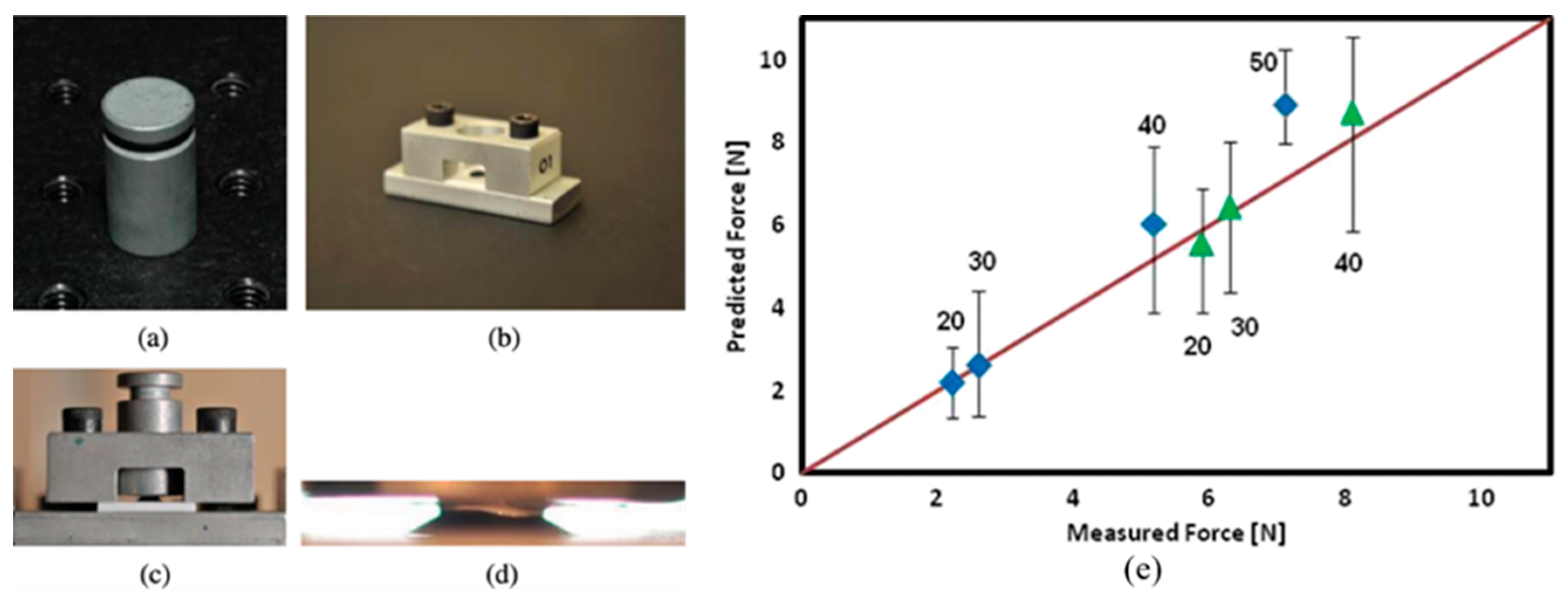
Figure 2.
(a-d) Measured scraping forces as a function of scraping displacement, investigating the effects of (a) substrate pre-set temperature (Tsub), (b) drop height (H), and (c) droplet temperature (Tdrop) under low and (d) high residual stress. (e-g) The effects of (e) substrate pre-set temperature, (f) drop height, and (g) droplet temperature on Fmax and K0. (h) The effects of droplet temperature and residual stress on K0. [56].
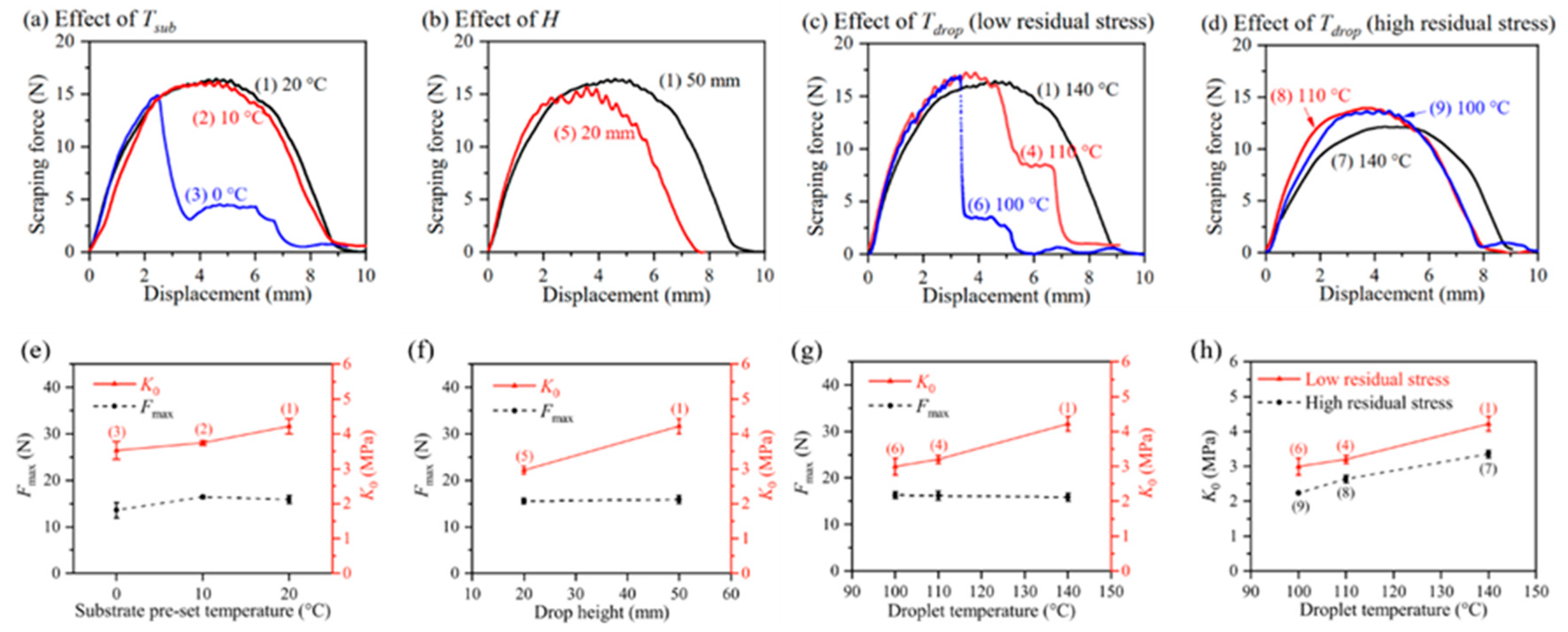
Figure 3.
Secondary electron images obtained during nano-indentation: (a) pre-indentation, (b) during indentation, and (c) post-indentation. [59].
Figure 3.
Secondary electron images obtained during nano-indentation: (a) pre-indentation, (b) during indentation, and (c) post-indentation. [59].
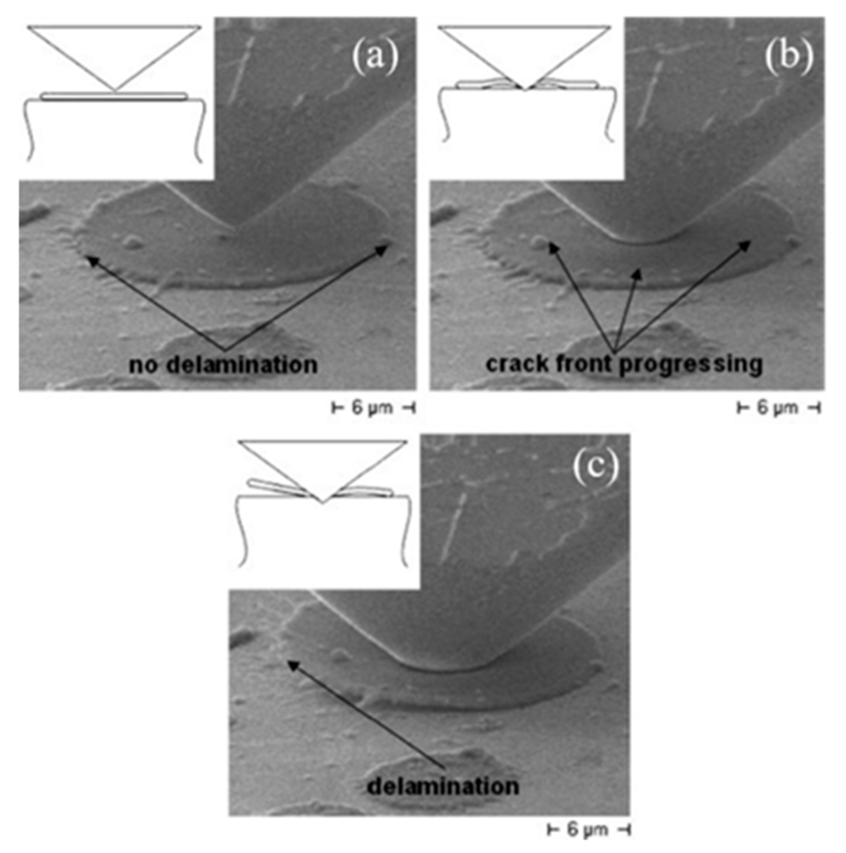
Figure 4.
(a) SEM micrograph illustrating the geometric dimensions and loading conditions used for examining FIB-milled cantilevers. The crystallographic orientation of each cantilever was determined via EBSD (inset). (b) Typical load-displacement curves obtained from cantilevers milled in the three crystallization regions of a single splat, along with respective post-bending SEM micrographs obtained at the interface. (c) The calculated fracture strength as a function of the normalized distance from the splat center; uncertainty was determined as the standard error of regression in each region. [61].
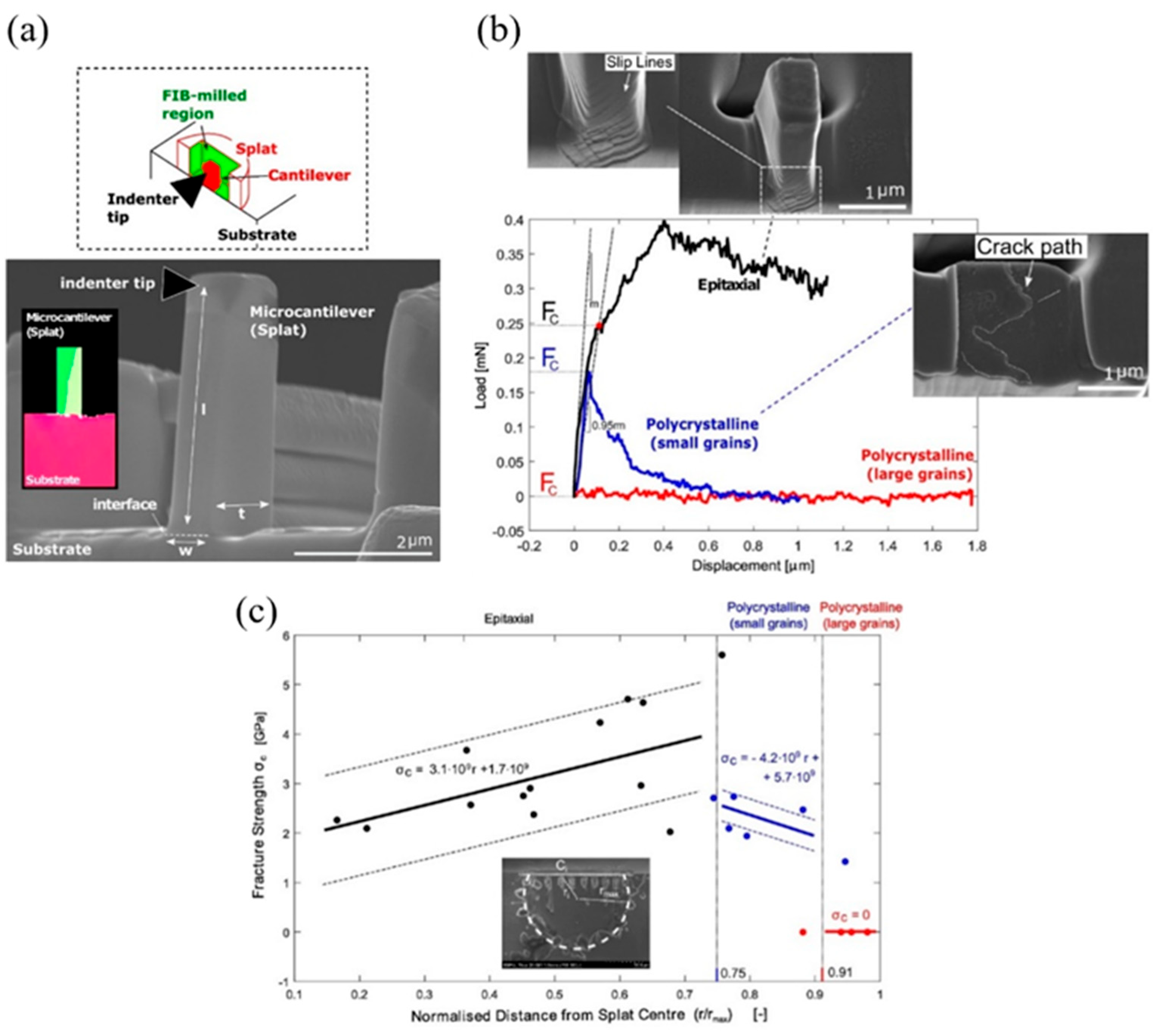
Figure 5.
(a) Schematic representation of the scratch testing procedure on splats [63], (b) schematic of the scratch test on the single splat, where a typical lateral force vs. scratch distance curve during scratching on the single splat is shown [64].
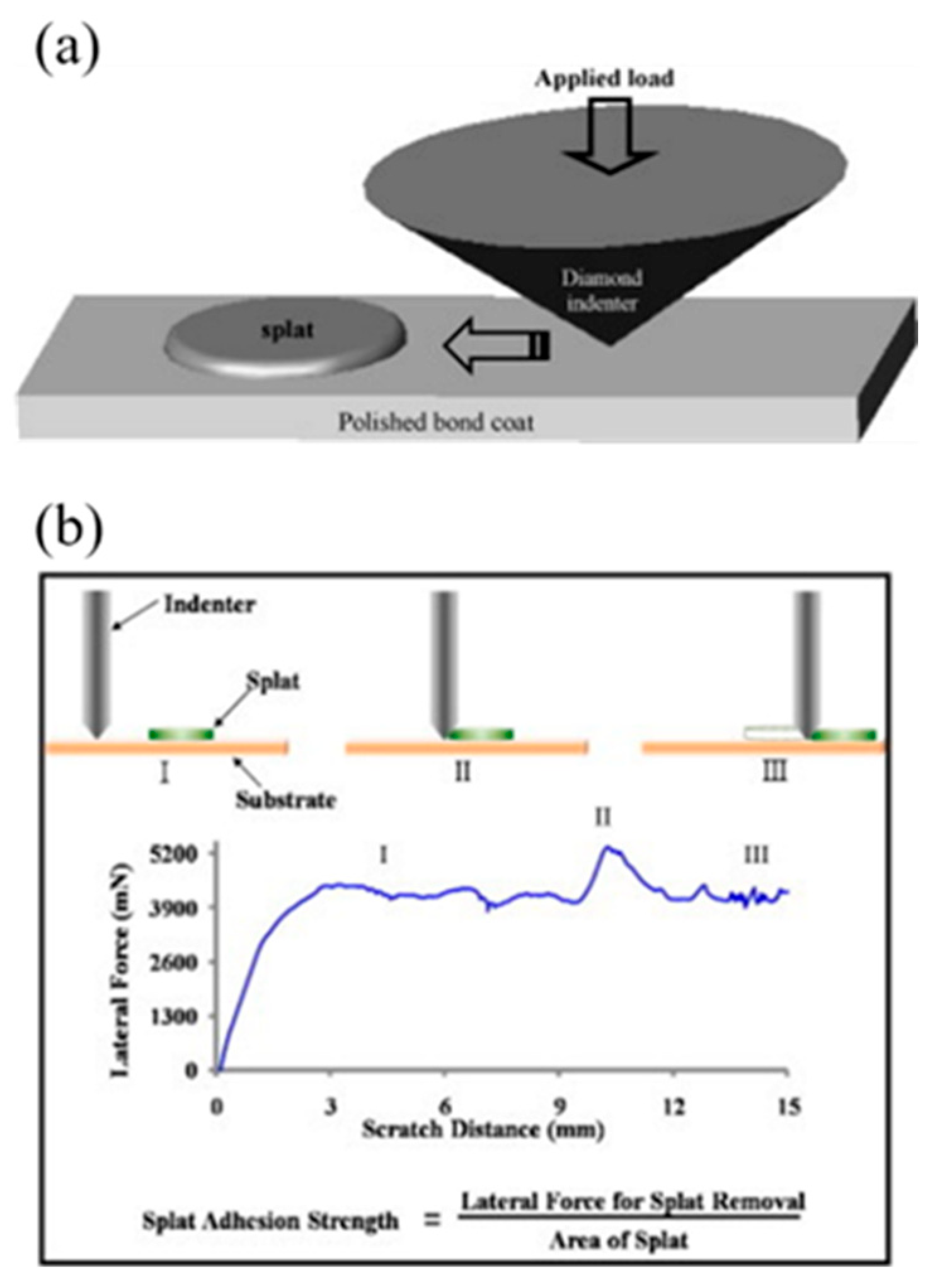
Figure 6.
(a) Schematic of the splat debonding mechanism. Curves of the penetration depth, lateral force, and acoustic emission signals against scratch distance for splats deposited on substrates preheated to (b) 400 °C, (c) 200 °C, and (d) 25 °C. FIB/SEM morphologies of splat/substrate interfaces: (e)–(f) center and edge positions (400 °C), (g)–(h) center and edge positions (200 °C), and (i)–(j) center and edge positions (25 °C). [67].
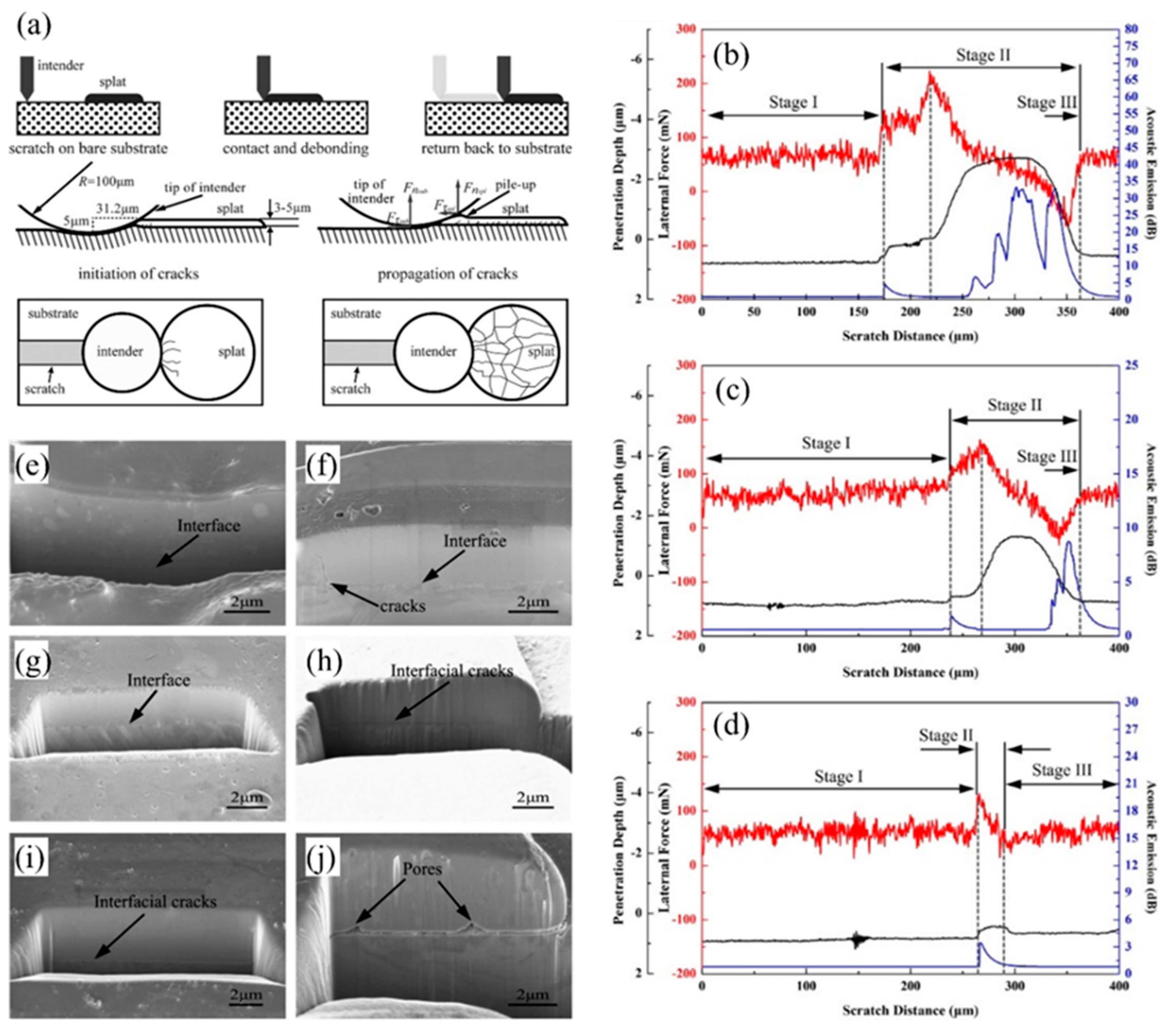
Figure 7.
Schematic illustration of the impact, spreading, and solidification of a single splat. [69].
Figure 7.
Schematic illustration of the impact, spreading, and solidification of a single splat. [69].
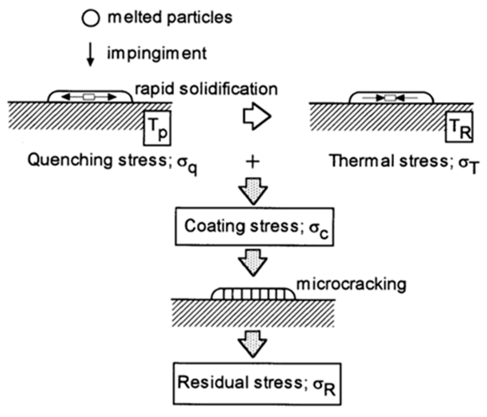
Figure 8.
(a) Residual stress measured in Mo splats by XRD, thermal sprayed on stainless substrates under various spray powers. Micrographs of splats formed under (b) low, (c) medium, and (d) high spray power conditions. [77].
Figure 8.
(a) Residual stress measured in Mo splats by XRD, thermal sprayed on stainless substrates under various spray powers. Micrographs of splats formed under (b) low, (c) medium, and (d) high spray power conditions. [77].
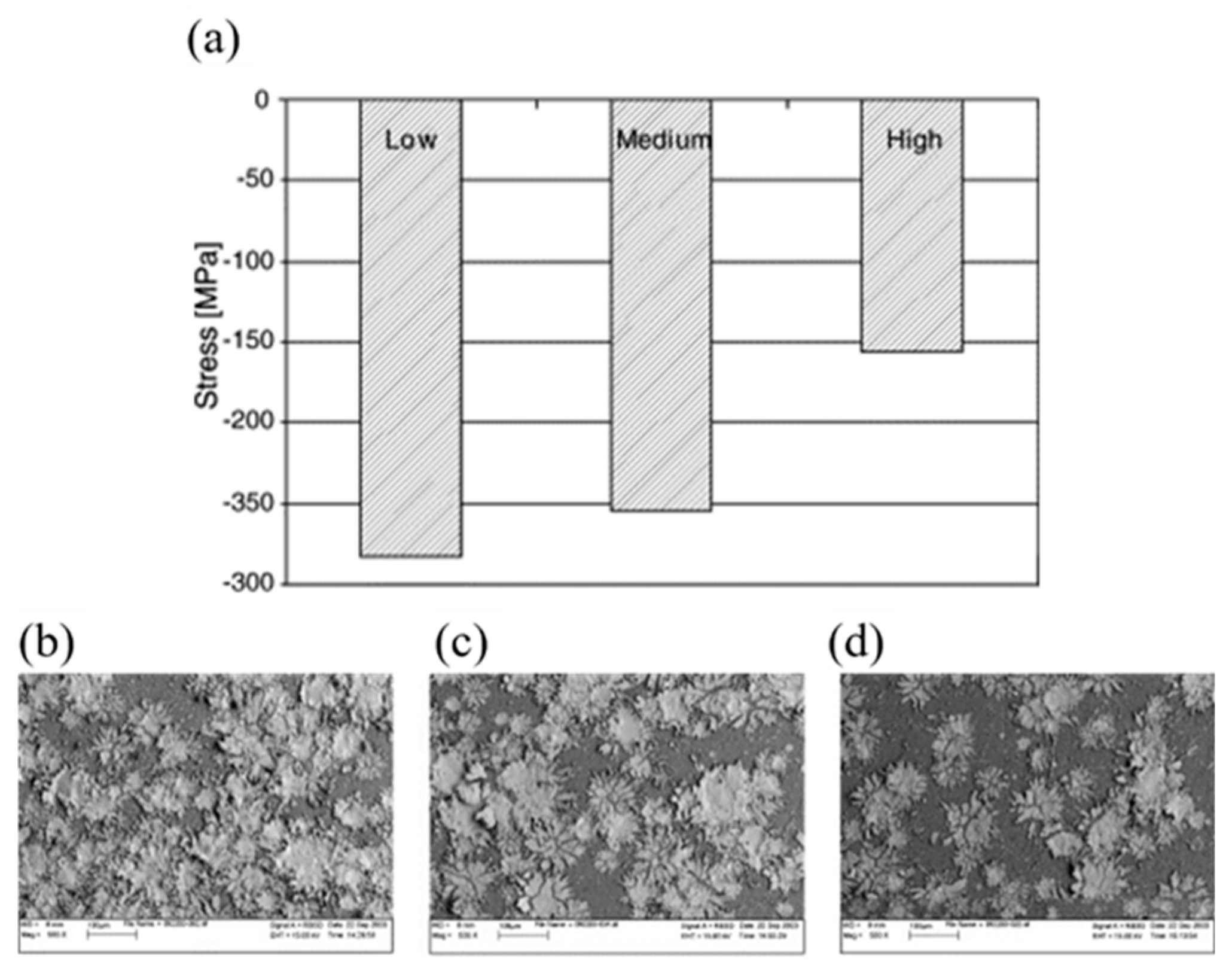
Figure 9.
Variation of the residual stress in a single splat deposited at different (a) particle velocities and (b) temperatures. (c) Secondary electron image of a typical remelted splat. (d) Residual stress harbored by a set of laser-remelted single splats. [79].
Figure 9.
Variation of the residual stress in a single splat deposited at different (a) particle velocities and (b) temperatures. (c) Secondary electron image of a typical remelted splat. (d) Residual stress harbored by a set of laser-remelted single splats. [79].
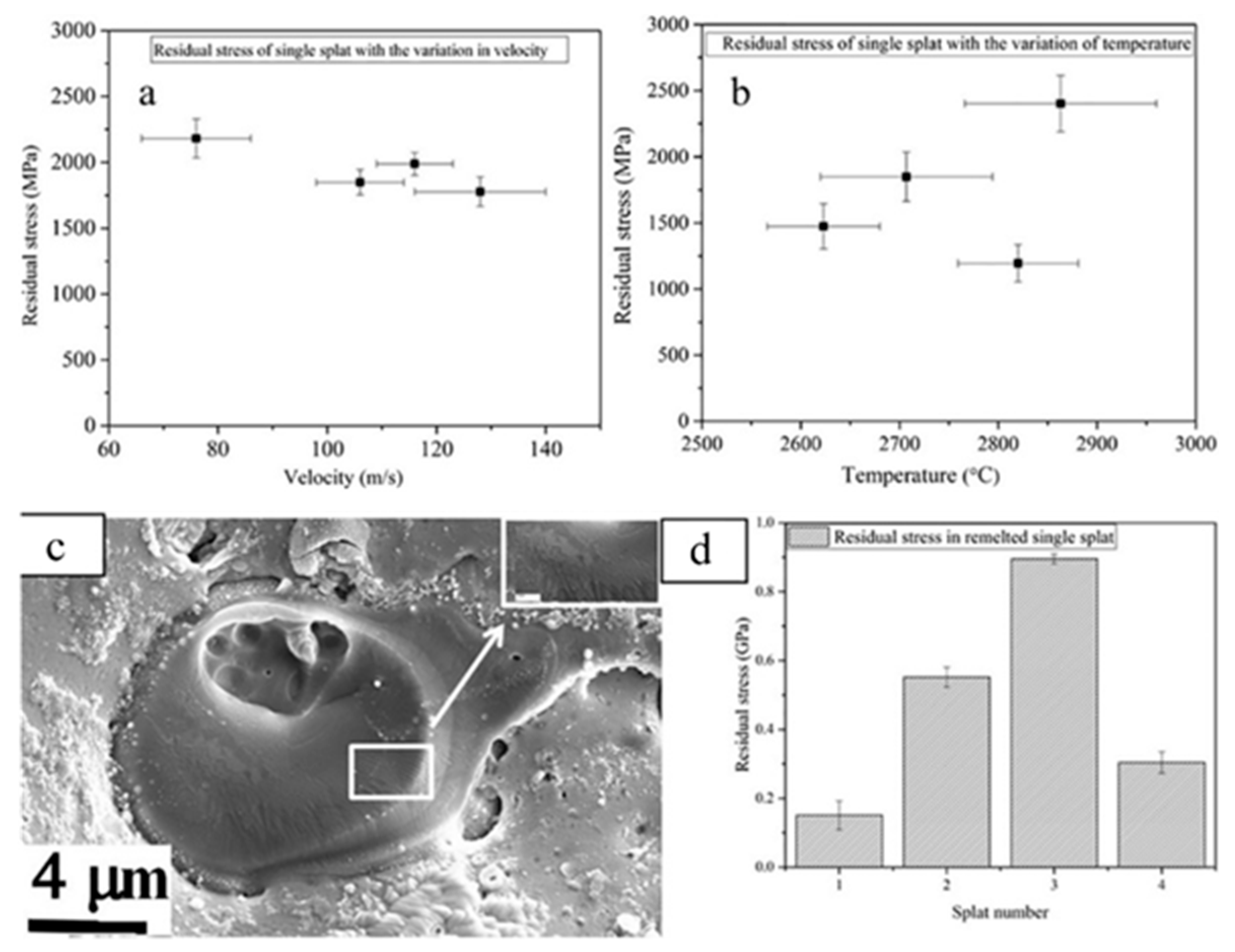
Figure 10.
(a) Example of a micron-scale ring-core FIB–DIC test. (b) Example of a high-magnification micrograph acquired before and (c) after milling. (d) Relaxation strain vs. milling depth for the Al2O3 splats for both large (microcracks) and the small (no cracks) splats, with SEM images of splats. (e) Relaxation strain vs. milling depth for the Al2O3−TiO2−ZrO2−CeO2 and (f) Ni-5wt.%Al splats. [84].
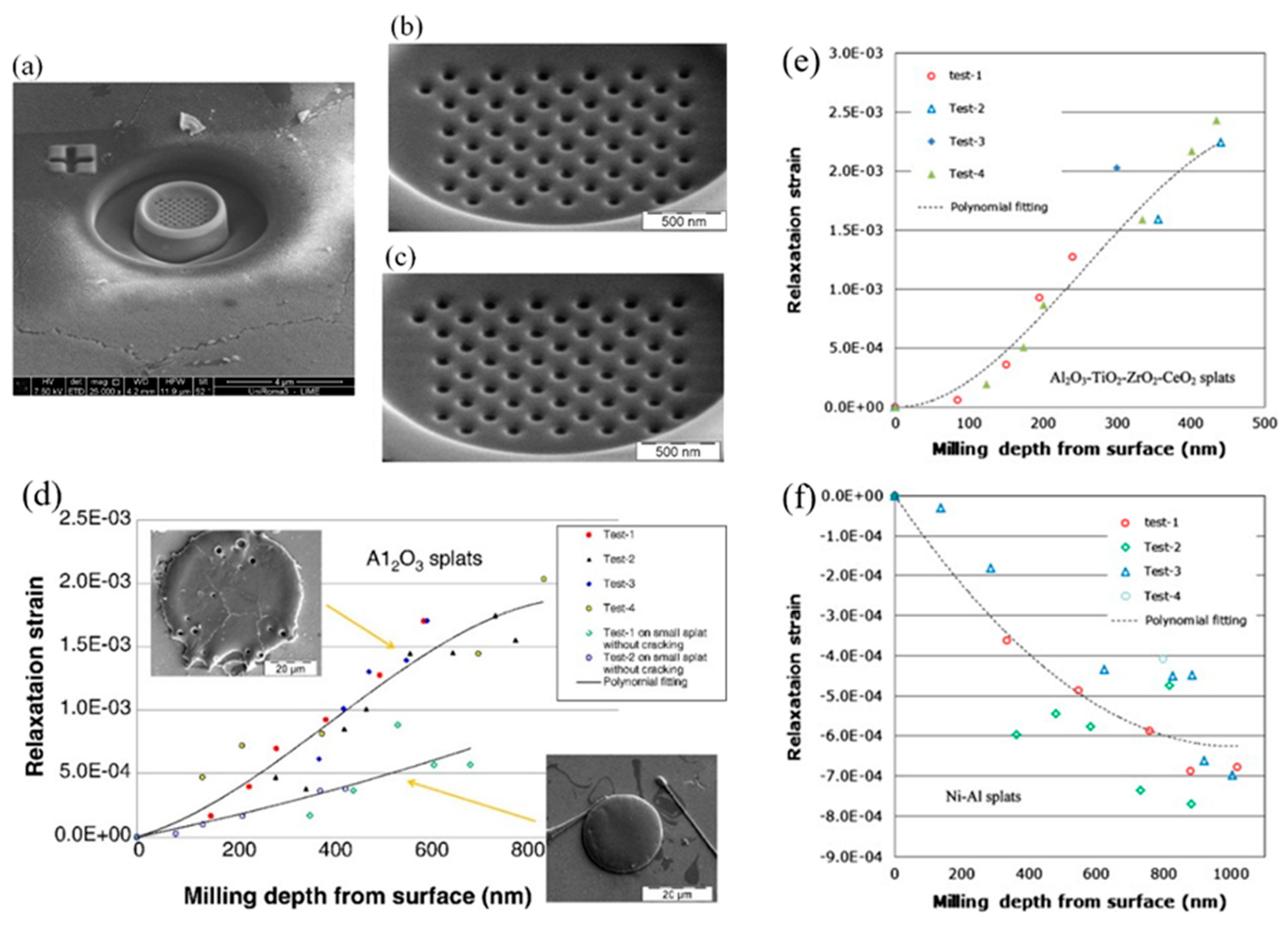
Figure 11.
(a) Distribution of the (GND) density within and below the single splat cross-section, illustrating the tendency for slip system activation. (b) In-plane σY linear elastic residual stress for the same system, showing a radially decreasing trend from the splat center and a low magnitude in areas corresponding to the onset of polycrystalline growth (stress relaxation areas). [61].
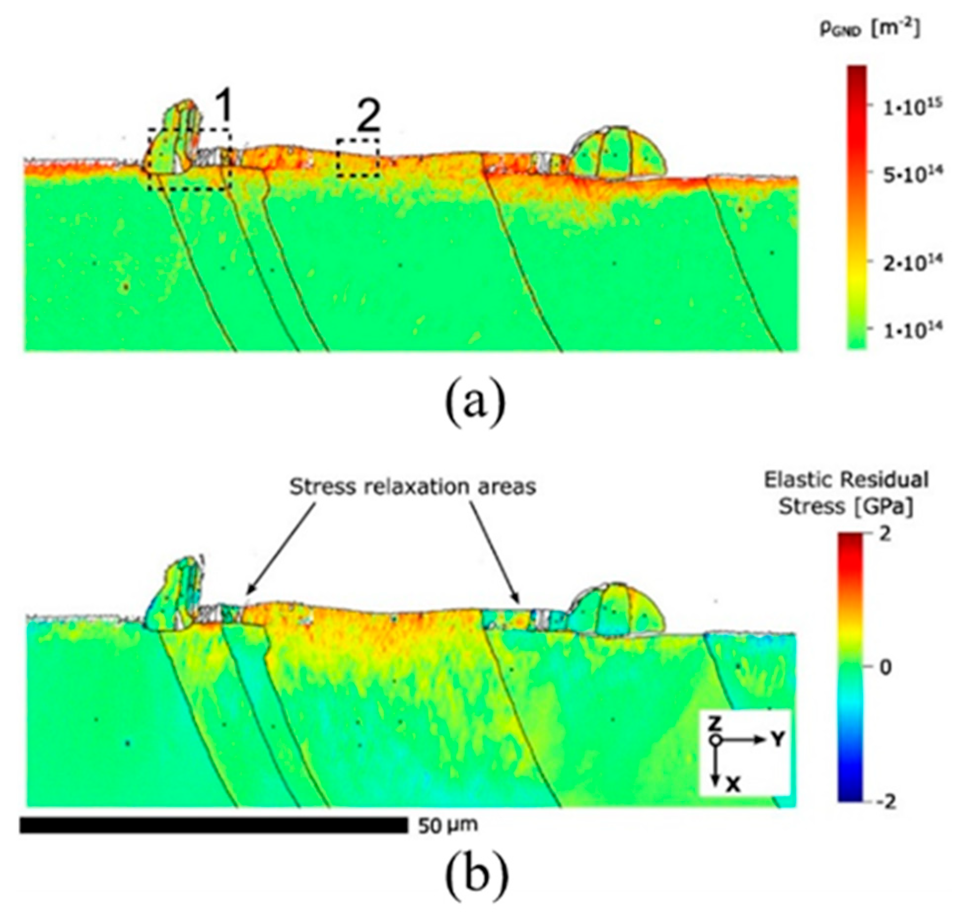
Figure 12.
(a) Experimental setup. (b) Example of measurements showing the variations in quenching strains (εq) and substrate temperature (T1) during the first, second, and third drops. (c) Measured εq during the steady state of the first drop as a function of T1 at impact velocities of 0.99 m/s (H = 50 mm) and 1.4 m/s (H = 100 mm). [90].
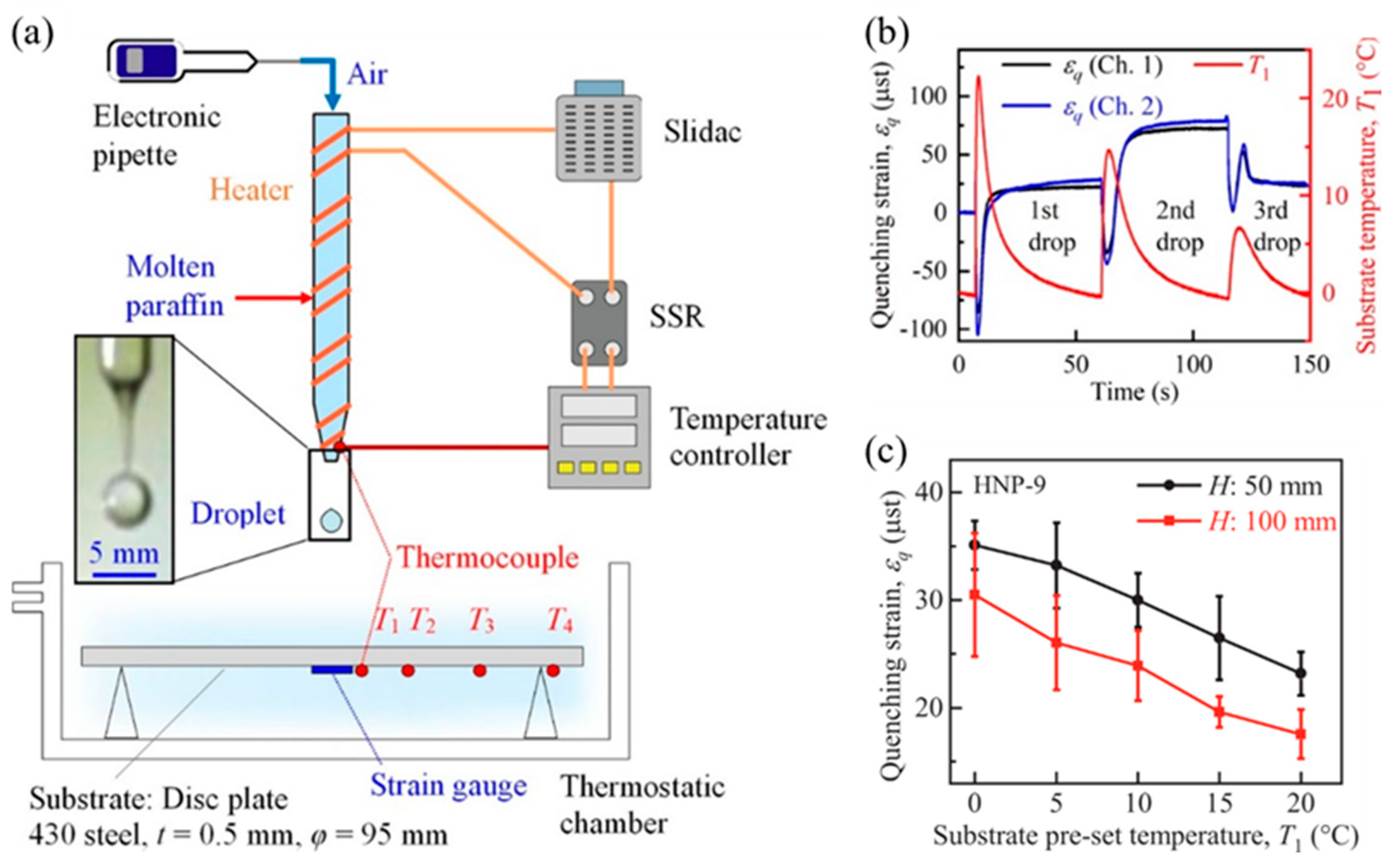
Figure 13.
(a) Schematic depiction of the impact, spreading, and cooling of a single splat. (b) Schematic illustration of the stress distributions within a single splat before and after various forms of stress relaxation. [34].
Figure 13.
(a) Schematic depiction of the impact, spreading, and cooling of a single splat. (b) Schematic illustration of the stress distributions within a single splat before and after various forms of stress relaxation. [34].
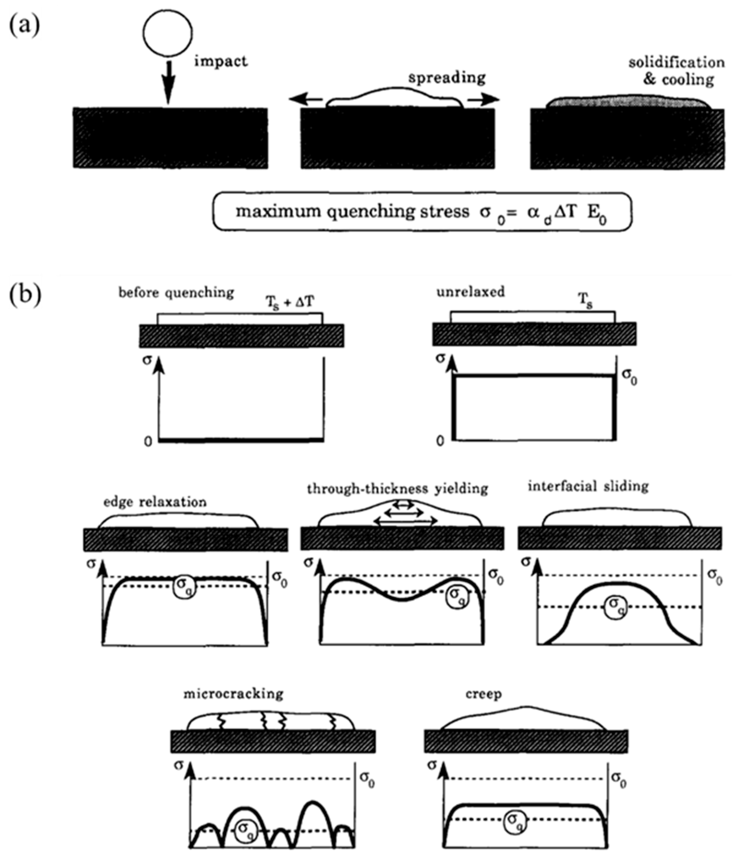
Figure 14.
(a) 2D model dimensions. (b) 2D thermal and mechanical boundary conditions. (c) 2D centerline radial stress distributions at discrete times. (d) Effect of substrate preheat on steady-state 2D radial stress distributions [93]. (e-f) Typical simulation results of the temperature distribution and structural deformation of the aluminum alloy splat and tool steel substrate at time 0.1 s: (e) temperature distribution, (f) stress distribution. (g) Magnified stress distribution and deformation of the splat (temperatures are in K, stresses are in Pa) [94].
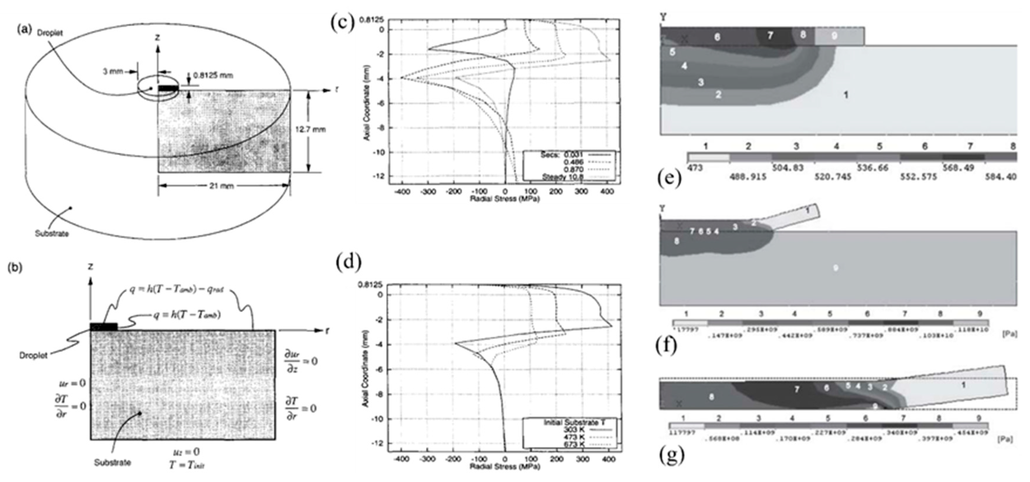
Figure 15.
(a)–(b) Surface topology identification using alpha-shape. (c)–(d) Generation of the STL mesh using normal vectors at point sets and Poisson surface reconstruction. (e) Residual stress profile along the axial direction and (f) the radial direction. Residual stress developed in the (g) x-direction and (h) y-direction for a single splat. [96].
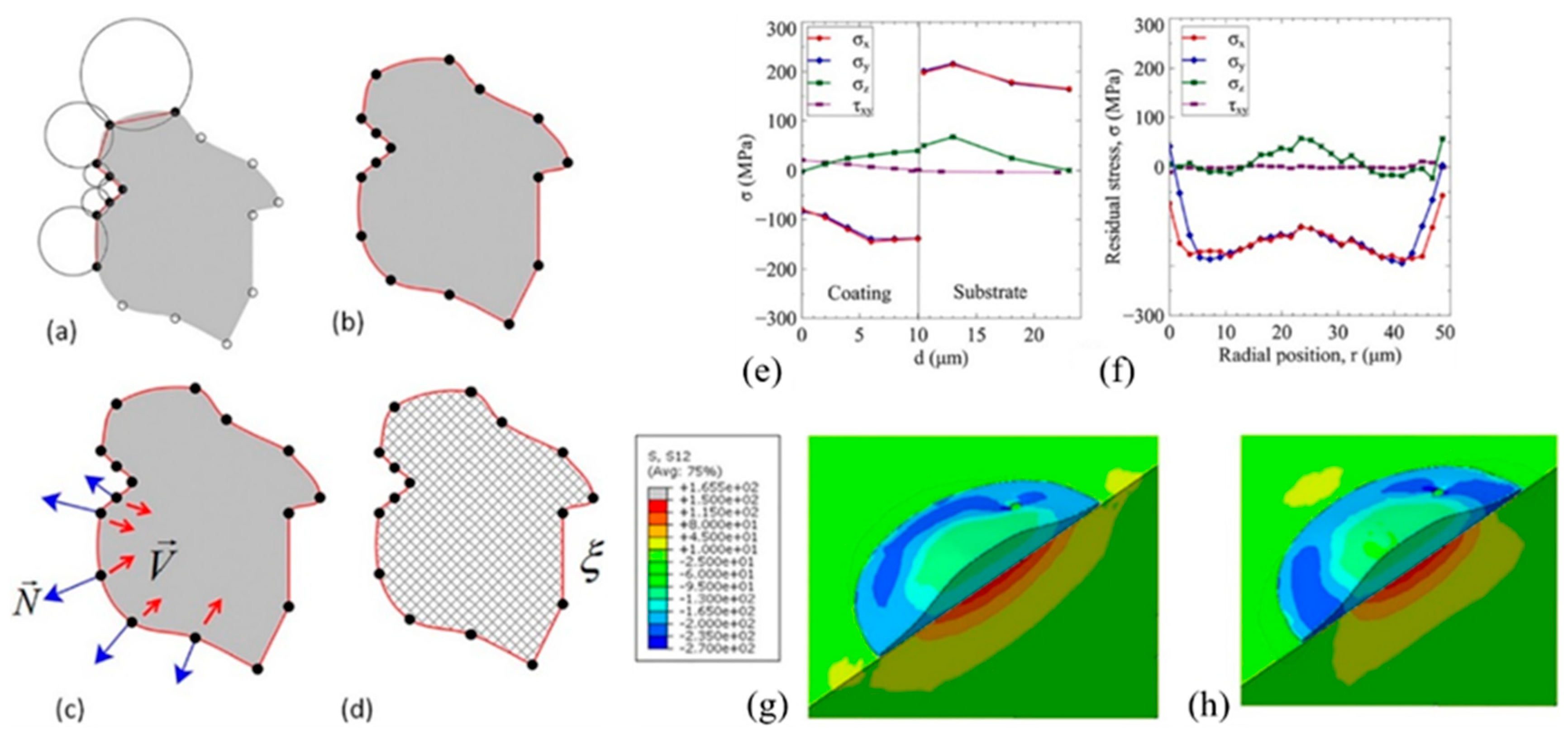
Figure 16.
Residual stresses acting in the XZ plane for an initial substrate temperature of 423 K with a YSZ particle impacting at 240 m/s, and the initial temperature of the particle ranges from 3250 to 3067 K. (a) Residual stresses in the YSZ particle (sectional isometric view). (b) Residual stresses in the stainless steel substrate (front view). [95].
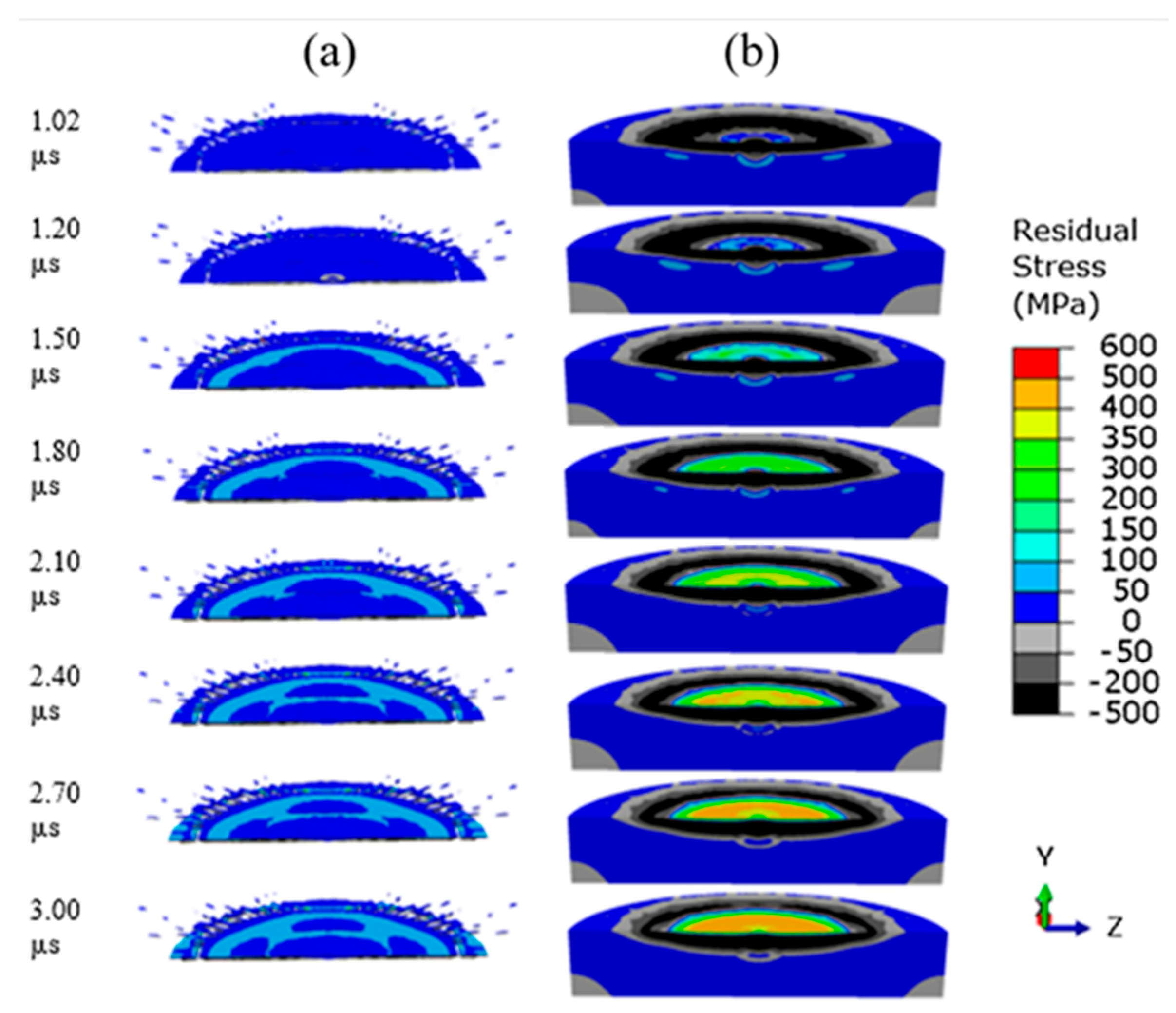
Figure 17.
(a) 2D axial-symmetric model. (b-c) Splat stress (σrr) and tensile strength for (b) candle wax and (c) HNP-9 with a changing pre-set substrate temperature at drop heights of 50 and 100 mm. Open symbols in (b) indicate that cracking occurred. (d-e) FEM results for (d) peeling stress (σzz) and (e) shear stress (τrz) distributions along the interface when substrate pre-set temperatures were 10, 15, and 20 °C [90]. (f-g) Comparison of experimental and numerical results for quenching strain variation under a pre-set substrate temperature of 20 °C and a drop height of 50 mm for (f) HNP-9 and (g) candle wax [91].
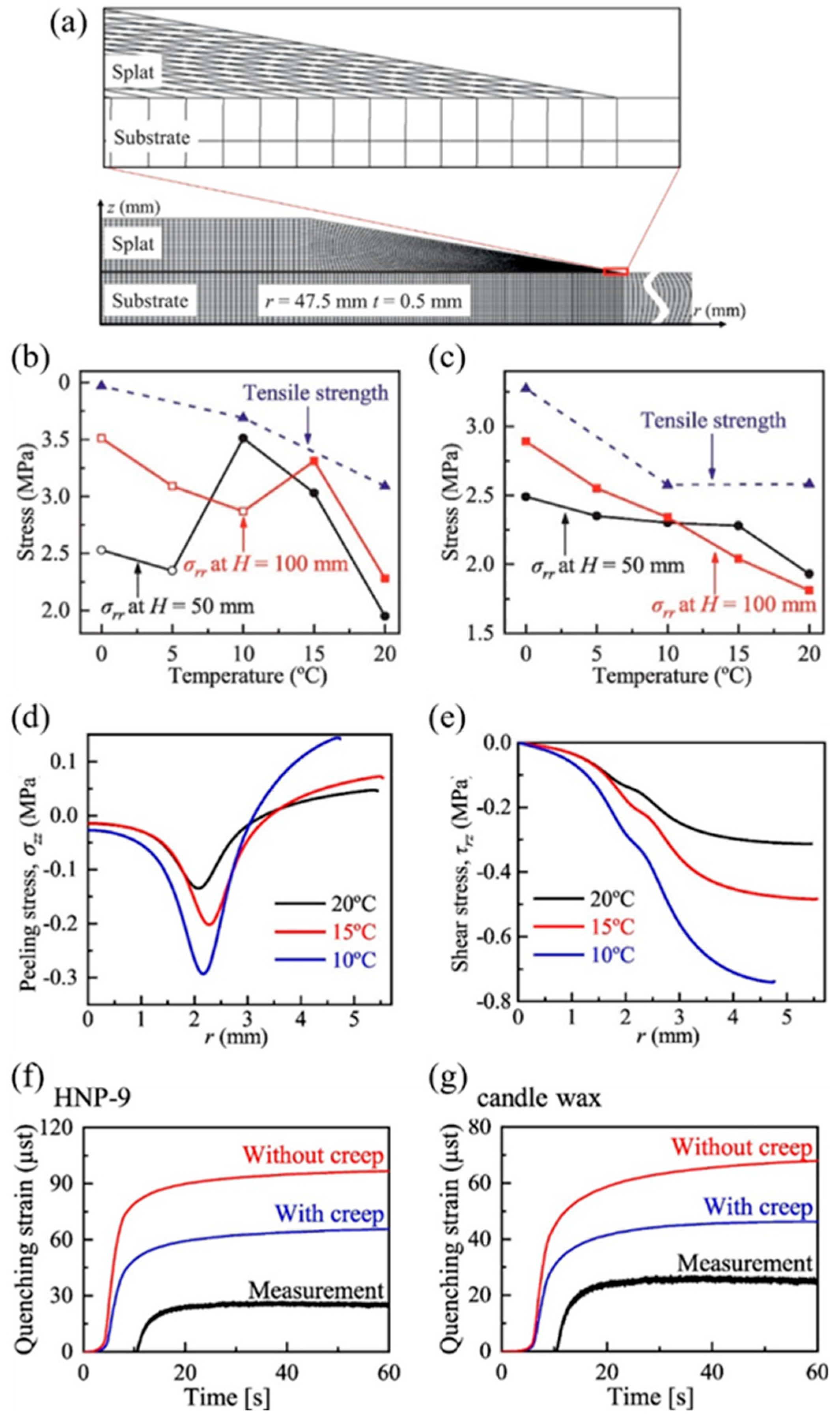
Figure 18.
(a-e) Development process of a numerical model used for determining splat deposition stress during droplet impact on textured grooves. (a) Groove model. (b) Droplet impact simulation. (c) and (d) Mesh block 1 from the VOF method directly converted into a tetrahedral FEM model. (e) Established coupling relationship between the solidified and non-solidified states of the splat. (f-h) Mean isotropic stress, von Mises stress, and principal stresses in a splat: (f) time-varying mean isotropic stress, (g) time-varying von Mises stress, and (h) distribution of the maximum principal stress. [78].
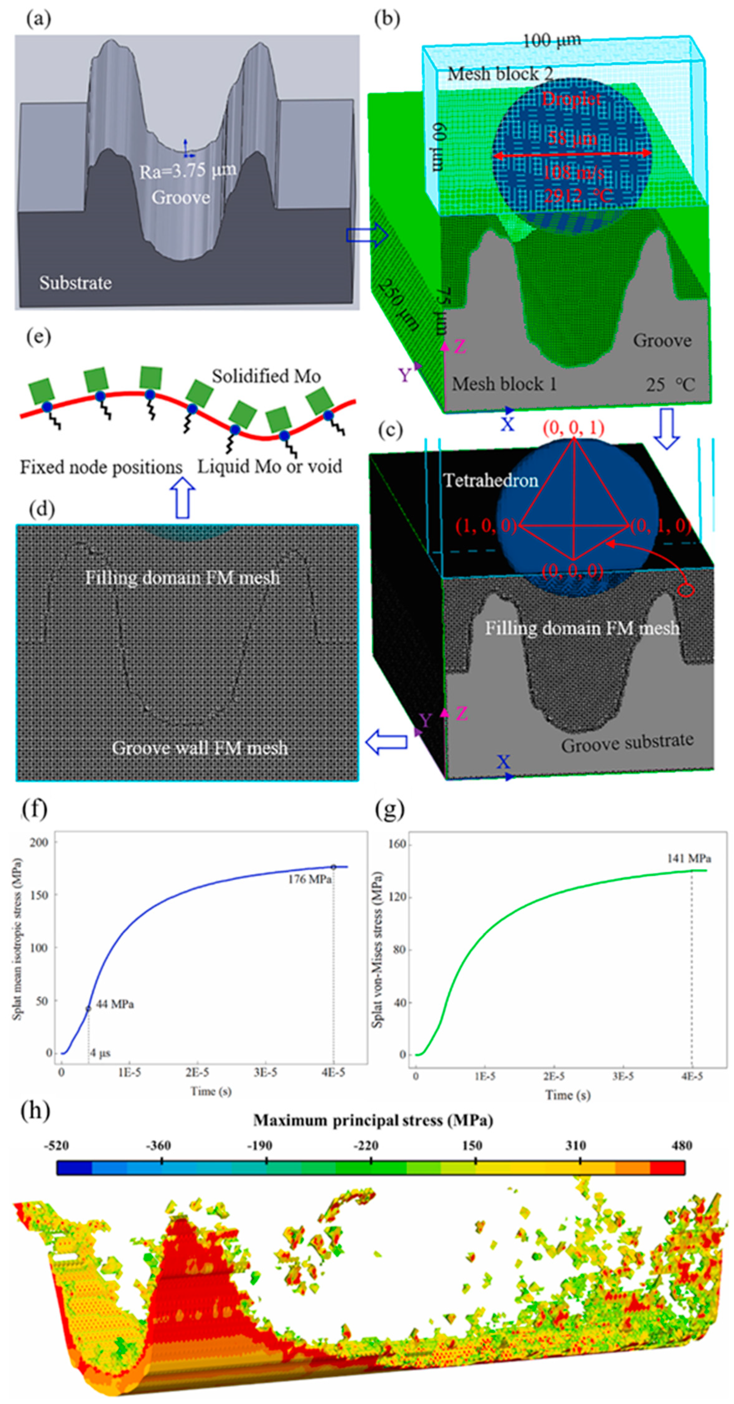
Figure 19.
(a) Variation of bonding strength of the H1, H2, H3, C1, C2-, and C3 hydroxyapatite coatings with compressive residual stresses [37]. (b) Adhesion strength of NiCrAl coatings deposited at different thicknesses on AISI 1020 substrates [106].
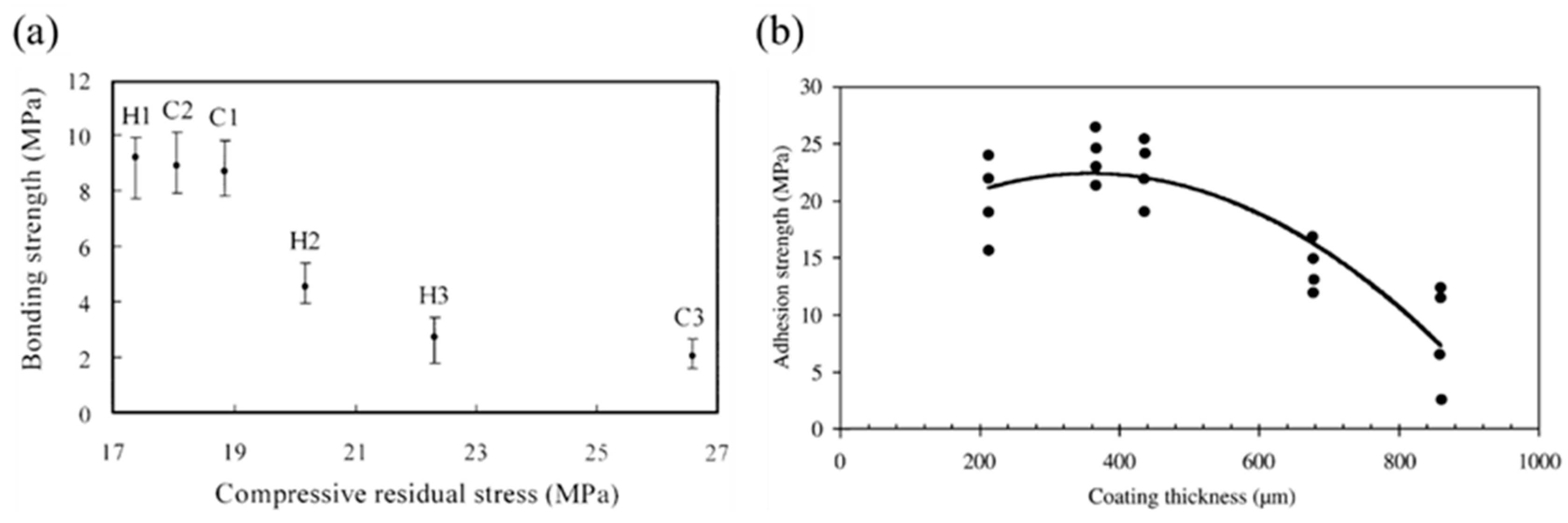
Figure 20.
(a) Evolution of the scraping forces and K(d) with scraping displacement in scraping tests. (b) Maximum scraping forces (Fmax) and calculated K0 reveal the effects of droplet temperature and residual stress. [56].
Figure 20.
(a) Evolution of the scraping forces and K(d) with scraping displacement in scraping tests. (b) Maximum scraping forces (Fmax) and calculated K0 reveal the effects of droplet temperature and residual stress. [56].
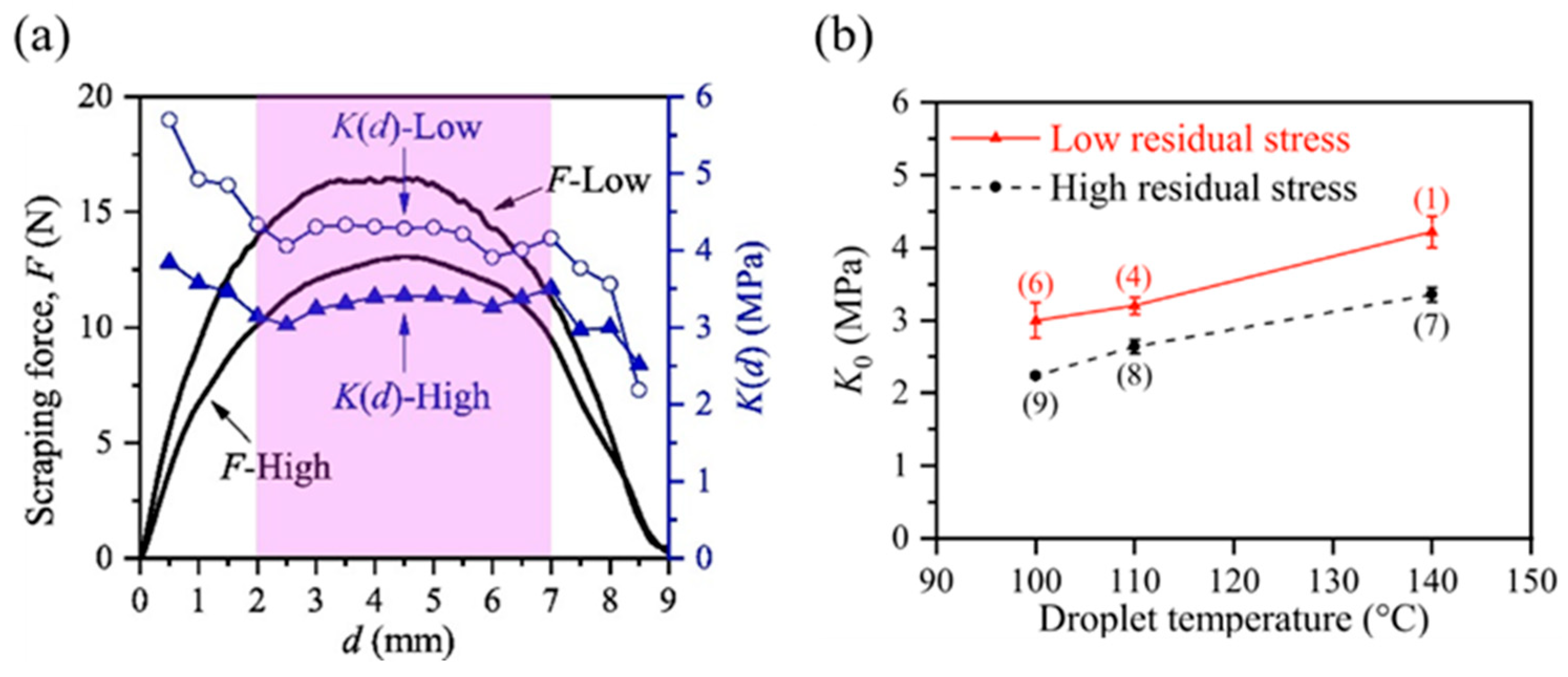
Figure 21.
Dependence of the fraction of disk splats and coating adhesion strength on substrate temperature. [115].
Figure 21.
Dependence of the fraction of disk splats and coating adhesion strength on substrate temperature. [115].
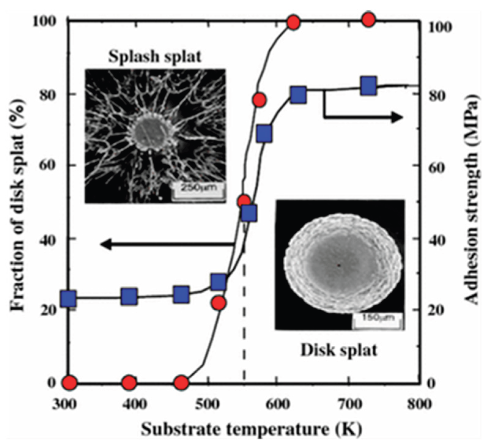
Figure 22.
The relationship between the Sommerfeld number and splat–substrate micro-bonding properties. [55].
Figure 22.
The relationship between the Sommerfeld number and splat–substrate micro-bonding properties. [55].
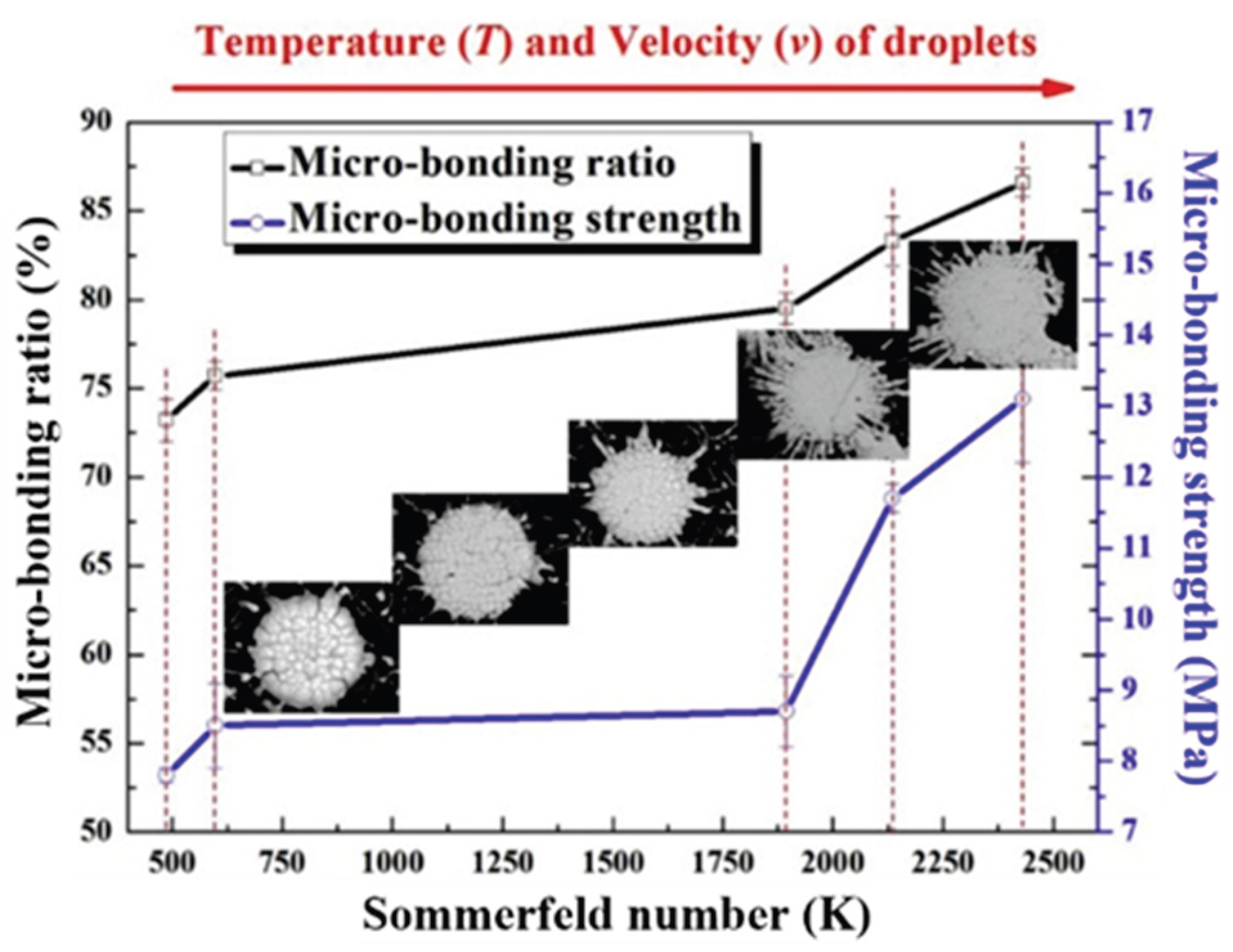
Figure 23.
Nano-scratch curve and morphology of (a) S1, (b) S6, (c) S8, and (d) S10 splats. (e) Failure load corresponding to the detachment of the center region or the peripheral region from the substrate. (f) Shear force and strength of different splats. S1–S5 splats were subsonic, and S6–S10 were supersonic. [57].
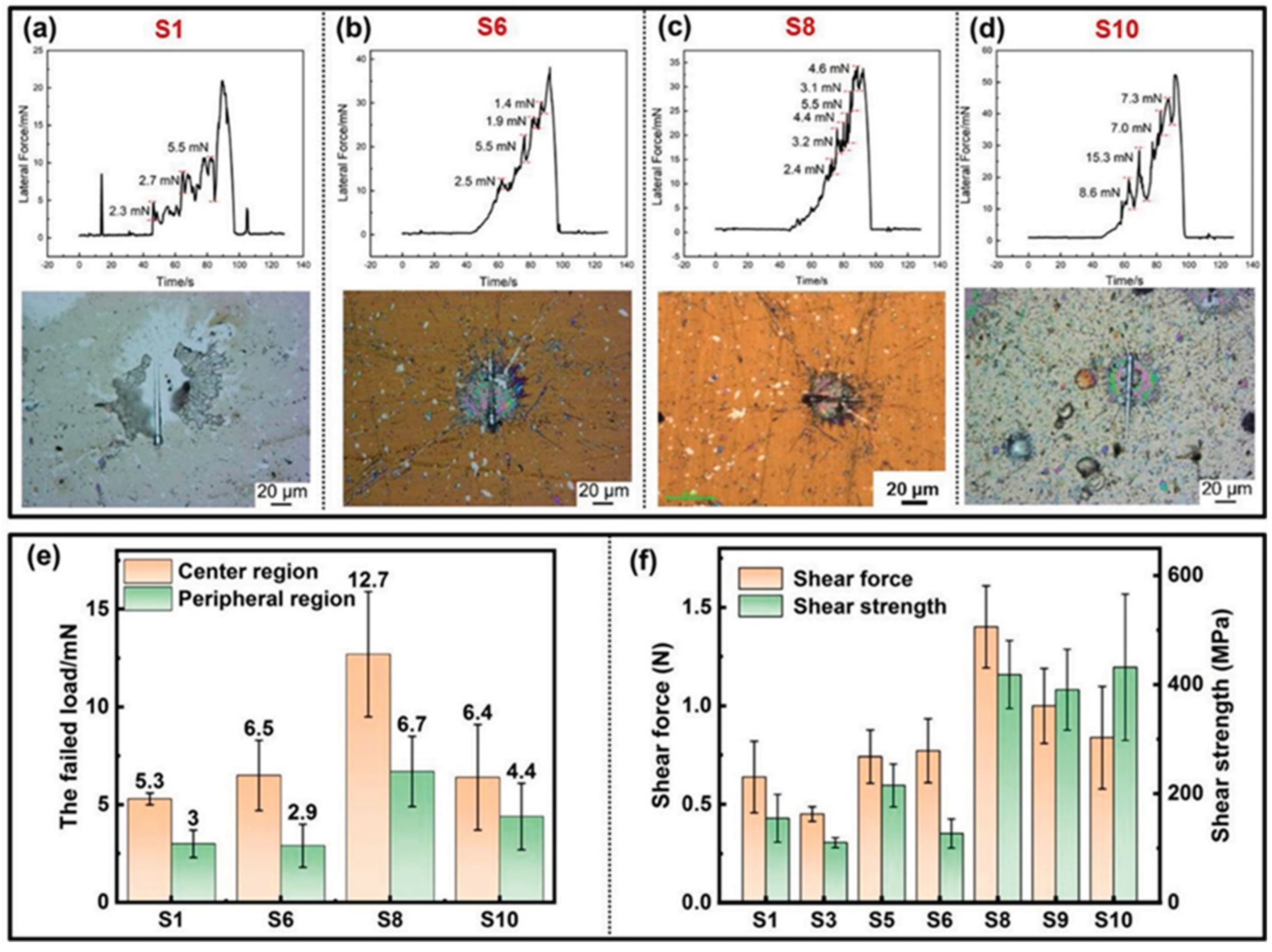
Figure 24.
(a) Illustration of the setup used for droplet impact testing. For the warm substrate, a mirror was placed below the transparent substrate to observe the bottom surface of the impacted droplet with a high-speed camera [130]. (b) Time-evolution of droplet impacts on an isothermal surface and (c) on a non-isothermal surface [129]. (d) Time-evolution of the splat-substrate interface, to quantify the transient solidification [130].
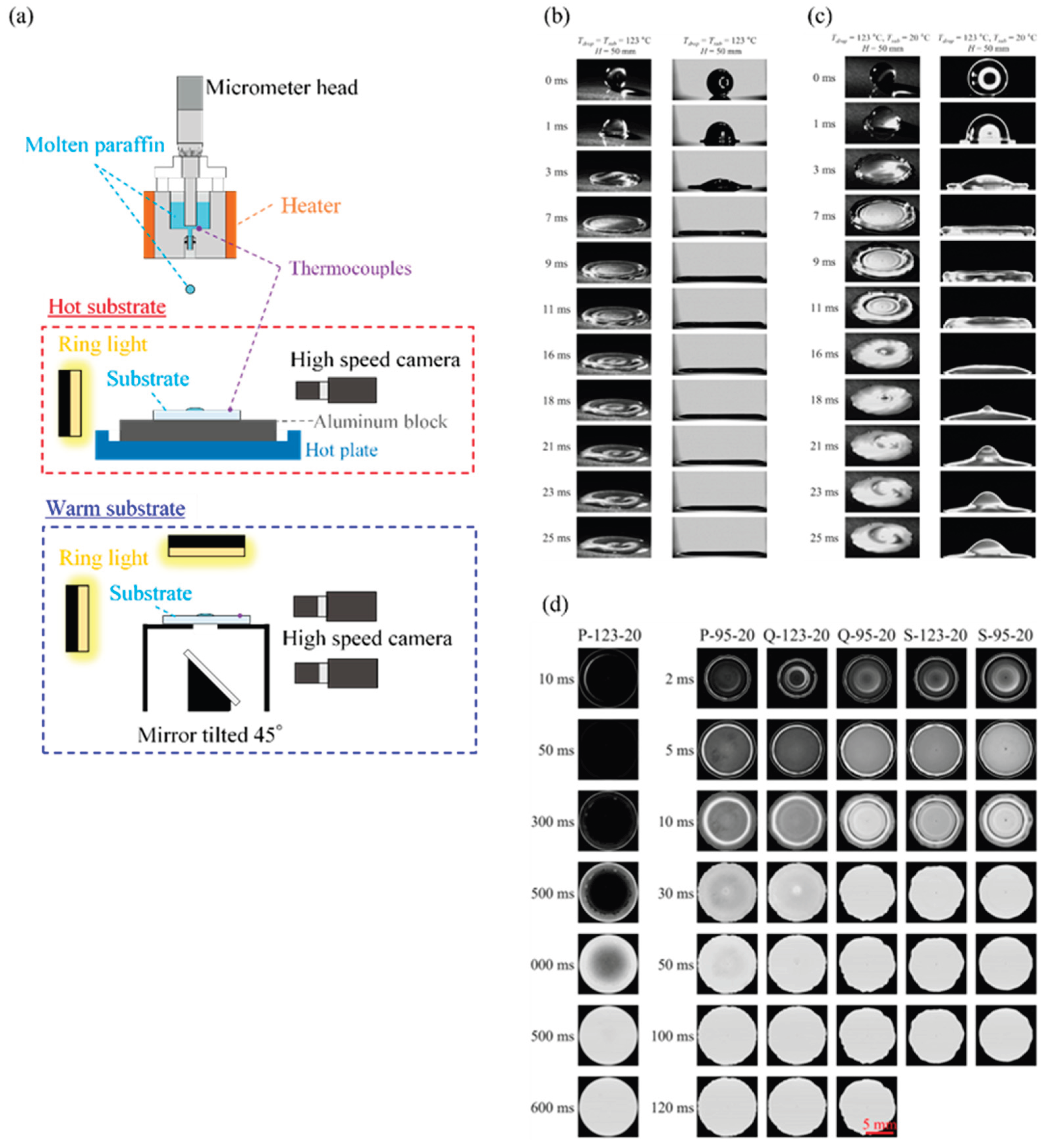

Table 1.
Summary of the experimental techniques used to determine bonding strength.
| Splat material | Substrate material | Method | Reference |
|---|---|---|---|
| Wax | Teflon, polyethylene | Tensile | [52] |
| ZnO nanorods on carbon fibers | Thermoplastic matrix | Scraping | [54] |
| Epoxy resin | Single carbon fiber | Scraping | [53] |
| Thermoplastic matrix | Single carbon fiber | Scraping | [54] |
| ZrO2-8 wt.%Y2O3 | CoNiCrAlY bond coat + nickel-base superalloy |
Scraping | [55] |
| Wax | 430 stainless steel | Scraping | [56] |
| ZrO2-8 wt.%Y2O3 | Stainless steel | Scraping | [57] |
| Al2O3 | Stainless steel 304 | Indentation | [59] |
| CoNiCrAlY | Ni-based superalloy | FIB-milled microcantilever beam bending |
[61] |
| Al2O3 | Ni-based superalloy | Scratch | [63] |
| Al2O3 with multiwall carbon nanotubes | Steel | Scratch | [64] |
| Al2O3, TiO2 | C20 steel | Scratch | [65] |
| Carbon nanofiller-reinforced Al2O3 | AISI 1020 steel | Scratch | [66] |
| Fe-based amorphous alloy | AISI 1045 steel | Scratch | [67] |
FIB, focused ion beam.
Table 2.
Summary of the experimental techniques used to determine residual stress.
| Splat material | Substrate material | Method | Reference |
|---|---|---|---|
| Mo | Steel, Al | XRD | [75] |
| Mo | Stainless steel | XRD | [76] |
| Mo | Stainless steel | XRD | [77] |
| Mo | Stainless steel 304 | XRD | [78] |
| YSZ | NiCrAlY bond coat + 316 stainless steel substrate |
Raman spectroscopy | [79] |
| Ni−5wt.%Al | Stainless steel | FIB–DIC material removal | [83] |
| Ni−5wt.%Al, Al2O3, (Al2O3−13wt.%TiO2)−8wt.%ZrO2−8wt.%CeO2 |
Ni−5wt.%Al bond coat + stainless steel substrate | HR-EBSD | [61] |
| Wax | Stainless steel 430 | Reverse calculation from strain | [89] |
| Wax | Stainless steel 430 | Reverse calculation from strain | [90] |
| Wax | Stainless steel 430 | Reverse calculation from strain | [91] |
YSZ, yttria-stabilized zirconia; XRD, X-ray diffraction; FIB, focused ion beam; HR-EBSD, high-resolution electron backscatter diffraction
Table 3.
Summary of the analytical methods used to determine residual stress.
| Splat material | Substrate material | Deformation | Method | Code | Reference |
|---|---|---|---|---|---|
| - | - | Elastic | Elastic model | - | [34] |
| Mo | Stainless steel 304 | Elastic | Elastic model with correction coefficients | - | [78] |
| YSZ | Steel alloy | Elastic–plastic | SPH-FEM | ABAQUS/Standard + ABAQUS/Explicit | [96] |
| Mo | Stainless steel 304 | Elastic | VOF + FEM | FLOW-3D + ABAQUS | [78] |
| Carbon steel | Carbon steel | Elastic, creep | FEM | ABAQUS | [93] |
| Al alloy, Bi | Steel | Elastic | FEM | ANSYS | [94] |
| YSZ | Stainless Steel | Elastic–plastic | FEM | ABAQUS/Explicit | [95] |
| Wax | Stainless steel 430 | Elastic | FEM | ABAQUS/Standard | [90] |
| Wax | Stainless steel 430 | Elastic, creep | FEM | ABAQUS/Standard | [91] |
YSZ, yttria-stabilized zirconia; SPH, smooth particle hydrodynamics; VOF, volume of fluid; FEM, finite element method.
Disclaimer/Publisher’s Note: The statements, opinions and data contained in all publications are solely those of the individual author(s) and contributor(s) and not of MDPI and/or the editor(s). MDPI and/or the editor(s) disclaim responsibility for any injury to people or property resulting from any ideas, methods, instructions or products referred to in the content. |
© 2025 by the authors. Licensee MDPI, Basel, Switzerland. This article is an open access article distributed under the terms and conditions of the Creative Commons Attribution (CC BY) license (http://creativecommons.org/licenses/by/4.0/).
Copyright: This open access article is published under a Creative Commons CC BY 4.0 license, which permit the free download, distribution, and reuse, provided that the author and preprint are cited in any reuse.


