
Submitted:
01 September 2025
Posted:
03 September 2025
Read the latest preprint version here
Abstract
The irreversible cyclic strain/stress in battery electrodes during ion intercalation/deintercalation drives mechanical energy dissipation, accelerating cycle life degradation. However, the lack of quantitative methods to assess this dissipation hinders a mechanistic understanding of mechanical behavior in electrochemical systems. Here, a theoretical framework is proposed to quantify stress and strain energy evolution in practical heterogeneous composite electrodes. Under assumptions of plane stress and elastic deformation, the average stress/strain energy per cycle can be derived for battery electrode during dynamic ion insertion/extraction.
Keywords:
chemical stress
; strain energy
; chemical strain
; composite electrode
; ion insertion
Stress and strain energy evolution during battery cycling critically governs electrode degradation and performance decline. [1,2] During electrochemical cycling, ion concentration variations induce dimensional/volume changes in electrodes. These changes generate two distinct stress contributions: (1) diffusion-induced stresses arising from concentration gradients within active particles,[3,4] and (2) macroscopic electrode level stresses in film-substrate electrode systems caused by constraints from inactive cell components (e.g., current collectors) and geometric limitations. [2,5,6,7,8,9] These stresses trigger mechanical degradation through electrode fracturing, particle disintegration, and contact loss at interfaces, ultimately causing capacity fade and cell failure. [6,10,11,12,13] Meanwhile, the strain energy accumulated during deformation drives crack initiation and propagation as stored energy converts to surface energy during fracture. [14] Notably, cracks often originate at active/inactive material interfaces, emphasizing the necessity to study DIS and strain energy evolution at electrode levels.
Real-time observation techniques, such as in situ X-ray or electron-based microscopy, reveal atomic-scale deformation mechanisms but lack direct stress/strain quantification in practical porous composite electrodes composed of active particles, binders, and conductive agents. [15,16,17] Such investigations were made possible by the use of digital image correlation (DIC) or laser-based techniques employing Stoney’s equation combined with chemo-mechanical modeling. [9,18,19,20,21] Although theoretical studies have addressed DIS and strain energy at particle scales, [14,22,23,24,25] electrode-level investigations remain limited. Bridging this gap is essential to mitigate fracture-related degradation and optimize next-generation batteries through stress-engineered electrode designs.
In this work, a theoretical framework was developed for estimating stress and strain energy generation during ion insertion/extraction in practical battery electrodes with current collector substrates. To simplify the analysis, we assumed a homogeneous ion concentration distribution within the electrode. The electrode’s porous structure ensures that ion diffusion predominantly occurs across the ligaments of the porous network rather than through the bulk thickness, thereby minimizing significant global concentration gradients. We further adopted a plane stress assumption and treated the deformation as purely elastic. Under plane stress and linear elasticity assumptions, the in-plane stress components and are expressed as:
where and are effective Young’s modulus and effective Poisson ratio of the composite electrode, respectively. and are the strain components along the x- and y-directions. The shear stress is given by:
where is effective shear modulus of the composite electrode, and is shear strain. For isotropic battery electrodes ( and ), and simplify to:
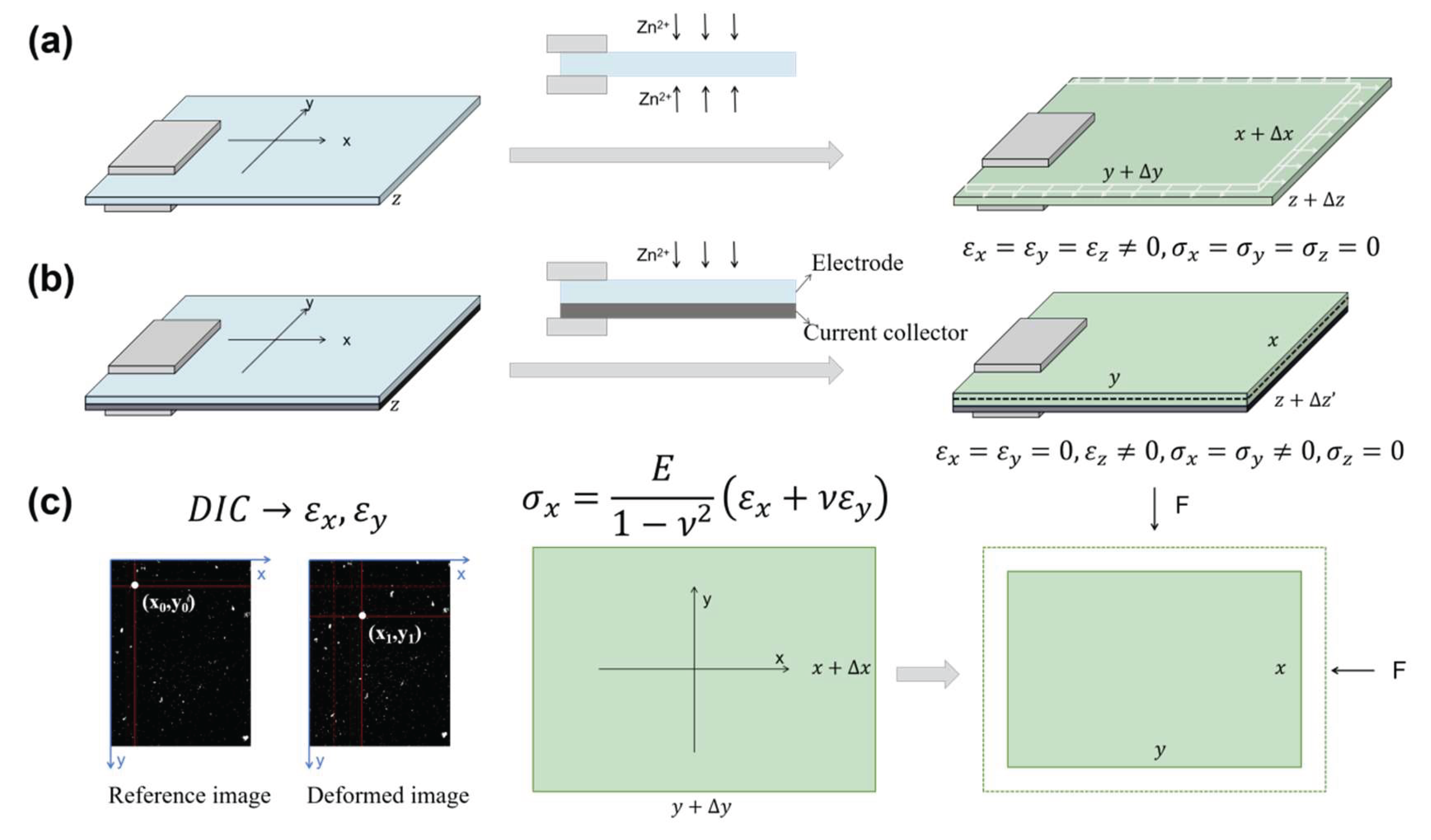
In freestanding electrodes (Figure 1a), ion insertion induces free volumetric expansion, generating isotropic tensile strains () across all directions. This strain can be experimentally measured by the Digital-Image-Correlation (DIC)-based approach. In practical electrodes where the active layer is bonded to current collectors (Figure 1b), however, this expansion is mechanically constrained by the substrate (e.g., Cu foil) and battery casing, resulting in bilayer stresses in film-substrate electrodes. Without casing constraints, this bilayer would bend, which is the principle exploited in traditional laser curvature methods for stress measurement. Under such conditions, total strain () comprises both bending strain and chemical strain (). The present study specifically examines film-substrate bilayer electrodes constrained within coin/pouch cells where the casing suppresses bending deformation. Consequently, the total strain equates solely to chemical strain from ion insertion. Due to the thin-film-substrate geometry of the electrode, we assume uniform stress distribution along the thickness direction.
If the bilayer electrode’s initial pre-cycling state was used as reference, the in-plane strains (x, y directions), , are approximately zero due to rigid current collector constraints, while the through-thickness strain (z-direction), , develops freely as the soft separator imposes negligible constraint, especially in pouch cells. This represents a reasonably valid approximation for systems with small volume change. It is also worth noting that local in-plane strains may not be strictly zero due to inhomogeneous deformation, which would affect the calculation of the spatial stress/strain energy distributions. For systems with small overall volume change, we consider in-plane strains negligible compared to freestanding electrode strains and thus exclude them from the current model.
To model these systems, we define the freestanding electrode at a given ion concentration as the reference state. The practical electrode (with identical ion content) is then conceptualized as the freestanding electrode compressed biaxially until its in-plane dimensions match those of the constrained system (Figure 1c). Assuming , the stress generated during ion insertion can be estimated by eq. (3), provided is measured as a function of ion concentration and stress-concentration coupling effects are neglected. For cases where , the effective strain () must substitute in eq. (3), necessitating experimental determination of .
Under a plane-stress state, the strain energy density (ue) is given by:
For isotropic conditions ( and ), this simplifies to:
The total strain energy (U) is then calculated by integrating over the electrode volume V:
where is the electrode volume and is a function of ion concentration.
The volumetric strain () during the “compression” of the freestanding electrode is expressed as:
Under plane stress (), Hooke’s law yields . Then, we have:
The electrode volume and its differential form are given by:
and
Substituting eq. (10) into eq. (6) gives the total strain energy U as follows:
The boundary condition at necessitates , yielding:
By experimentally measuring as a function of ion concentration and determining and , both stress and strain energy generated during cycling of the battery electrode can be quantified using eq. (3) and eq. (12).
To determine the effective Young’s modulus () and Poisson’s ratio () of the composite electrode, we can assume remains constant throughout the analysis, and is bounded using micromechanical homogenization frameworks. The actual electrode is a composite comprising active materials, conductive additive (Super P), and binder PVDF. We assume that the modulus of the three components is independent of the ion concentration. For the idealized non-porous binary composite comprising conductive additive Super P and binder PVDF, the lower bound of the effective bulk modulus (Km,l) and effective shear modulus (Gm,l) can be calculated using the iso-stress (Reuss series) homogenization framework as follows:[26]
The upper bound of the effective bulk modulus (Km,u) and effective shear modulus (Gm,u) can be calculated using the iso-strain (Voigt parallel) homogenization framework as follows:[27]
where and are the volume fractions of Super P and PVDF in the non-porous binary composite. and denote the bulk moduli of Super P and PVDF, respectively, while and represent their corresponding shear moduli. and are the volume of the Super P and PVDF, respectively.
To account for the inherent porosity of practical electrodes, the effective bulk modulus (Kpm) requires porosity-dependent corrections:[28,29]
where , and , representing the densities of the fully dense and porous Super P/PVDF binary composite matrix. and are the global volume fractions of Super P and PVDF within the fully dense matrix. and are the global volume fractions of Super P and PVDF within the porous --matrix. corresponds to Poisson’s ratio of the porous matrix. Substituting and in eq. (15) with , or , yields the lower bound and upper bound of the effective bulk modulus (Kpm) of porous Super P/PVDF binary composite matrix.
The effective bulk modulus Ke of the whole porous electrode is given by:[28]
where , , , , , and . is the volumetric fraction of active material within the porous composite electrode. and are bulk modulus and Poisson ratio of the active material. Then, the effective Young’s modulus of the whole porous electrode can be calculated by:
Using the above theoretical framework and in situ DIC-measured chemical strain data, the stress and strain energy in practical battery electrodes under operational cycling conditions can be calculated.
In conclusion, a theoretical framework was developed to quantify stress and strain energy evolution in practical battery electrodes with current collectors during ion insertion/extraction cycles. The model integrates in situ strain data from freestanding electrodes, measured via DIC, under plane stress conditions and linear elastic assumptions. To estimate the effective mechanical properties of composite electrodes, iso-stress (Reuss) and iso-strain (Voigt) homogenization models were employed combined with porosity-dependent corrections, to compute bounds for the effective Young’s modulus. This work establishes a foundational methodology for assessing stress evolution and mechanical energy dissipation during battery cycling.
References
- M. K. S. Verma, S. Basu, K. S. Hariharan, S. M. Kolake, T. Song, and J. Jeon, Journal of The Electrochemical Society 164, A3426 (2017).
- K. Li, S. Wang, X. Shi, and Y. Huang, Acta Mechanica Solida Sinica (2025).
- Verma, A. Singh, and A. Colclasure, JOM 76, 1171 (2024).
- X. Zhang, W. Shyy, and A. Marie Sastry, Journal of The Electrochemical Society 154, A910 (2007).
- V. A. Sethuraman, N. Van Winkle, D. P. Abraham, A. F. Bower, and P. R. Guduru, J Power Sources 206, 334 (2012).
- A. Mukhopadhyay, A. Tokranov, X. Xiao, and B. W. Sheldon, Electrochimica Acta 66, 28 (2012).
- J. M. Tarascon and M. Armand, Nature 414, 359 (2001).
- Tokranov, B. W. Sheldon, P. Lu, X. Xiao, and A. Mukhopadhyay, Journal of The Electrochemical Society 161, A58 (2014).
- A. Mukhopadhyay, A. Tokranov, K. Sena, X. Xiao, and B. W. Sheldon, Carbon 49, 2742 (2011).
- D. Zane, A. Antonini, and M. Pasquali, J Power Sources 97-98, 146 (2001).
- Mukhopadhyay and B. W. Sheldon, Prog Mater Sci 63, 58 (2014).
- Y. Zhu and C. Wang, J Power Sources 196, 1442 (2011).
- W. Sheldon, S. K. Soni, X. Xiao, and Y. Qi, Electrochemical and Solid-State Letters 15, A9 (2011).
- R. Deshpande, Y.-T. Cheng, M. W. Verbrugge, and A. Timmons, Journal of The Electrochemical Society 158, A718 (2011). [CrossRef]
- S.-C. Chao, Y.-C. Yen, Y.-F. Song, Y.-M. Chen, H.-C. Wu, and N.-L. Wu, Electrochemistry Communications 12, 234 (2010).
- Y. Tian, A. Timmons, and J. R. Dahn, Journal of The Electrochemical Society 156, A187 (2009). [CrossRef]
- L. Y. Beaulieu, K. W. Eberman, R. L. Turner, L. J. Krause, and J. R. Dahn, Electrochemical and Solid-State Letters 4, A137 (2001). [CrossRef]
- E. Chason and B. W. and Sheldon, Surface Engineering 19, 387 (2003). [CrossRef]
- V. A. Sethuraman, M. J. Chon, M. Shimshak, V. Srinivasan, and P. R. Guduru, J Power Sources 195, 5062 (2010). [CrossRef]
- V. A. Sethuraman, V. Srinivasan, A. F. Bower, and P. R. Guduru, Journal of The Electrochemical Society 157, A1253 (2010). [CrossRef]
- V. A. Sethuraman, M. J. Chon, M. Shimshak, N. Van Winkle, and P. R. Guduru, Electrochemistry Communications 12, 1614 (2010). [CrossRef]
- Y.-T. Cheng and M. W. Verbrugge, J Power Sources 190, 453 (2009). [CrossRef]
- Y. Hu, X. Zhao, and S. Zhigang, Journal of Materials Research 25, 1007 (2010). [CrossRef]
- H.-Y. Shadow Huang and Y.-X. Wang, Journal of The Electrochemical Society 159, A815 (2012). [CrossRef]
- X. Xiao, P. Liu, M. W. Verbrugge, H. Haftbaradaran, and H. Gao, J Power Sources 196, 1409 (2011).
- A. Reuss, 9, 49 (1929).
- W. Voigt, Annalen der Physik 274, 573 (1889). [CrossRef]
- E. M. C. Jones, M. N. Silberstein, S. R. White, and N. R. Sottos, Experimental Mechanics 54, 971 (2014). [CrossRef]
- L. J. Gibson and M. F. Ashby, Cellular Solids: Structure and Properties (Cambridge University Press, Cambridge, 1997), 2 edn., Cambridge Solid State Science Series.
Figure 1.
Illustration of (a) the chemical strain generation in freestanding electrode, (b) stress generation in practical electrode with current collector during ion insertion, and (c) the methodology to estimate stress in the practical electrode using the experimentally measured chemical strain.
Figure 1.
Illustration of (a) the chemical strain generation in freestanding electrode, (b) stress generation in practical electrode with current collector during ion insertion, and (c) the methodology to estimate stress in the practical electrode using the experimentally measured chemical strain.
Disclaimer/Publisher’s Note: The statements, opinions and data contained in all publications are solely those of the individual author(s) and contributor(s) and not of MDPI and/or the editor(s). MDPI and/or the editor(s) disclaim responsibility for any injury to people or property resulting from any ideas, methods, instructions or products referred to in the content. |
© 2025 by the authors. Licensee MDPI, Basel, Switzerland. This article is an open access article distributed under the terms and conditions of the Creative Commons Attribution (CC BY) license (http://creativecommons.org/licenses/by/4.0/).
Copyright: This open access article is published under a Creative Commons CC BY 4.0 license, which permit the free download, distribution, and reuse, provided that the author and preprint are cited in any reuse.


