1. Introduction
The problems of tracking stands for solar energy collectors have been widely studied recently because they can considerably increase the efficiency of solar panel systems by increasing the energy output and thus decreasing the price of energy produced [
2,
3,
6]. The maximum intensity of energy from the Sun absorbed by a plane perpendicular to direct solar radiation is approximately
. Assuming that quality collectors based on crystalline silicone are approximately 18–23 % efficient, the maximum output for a collector area
S = 1 m
2 is
Pmax = 200 W. This value decreases for inclined incidence. If we install a sun tracking device with a collector that is able to position the panel so that it is always perpendicular to the solar radiation, the energy output will be greater. The amount of energy produced
W is defined as
.
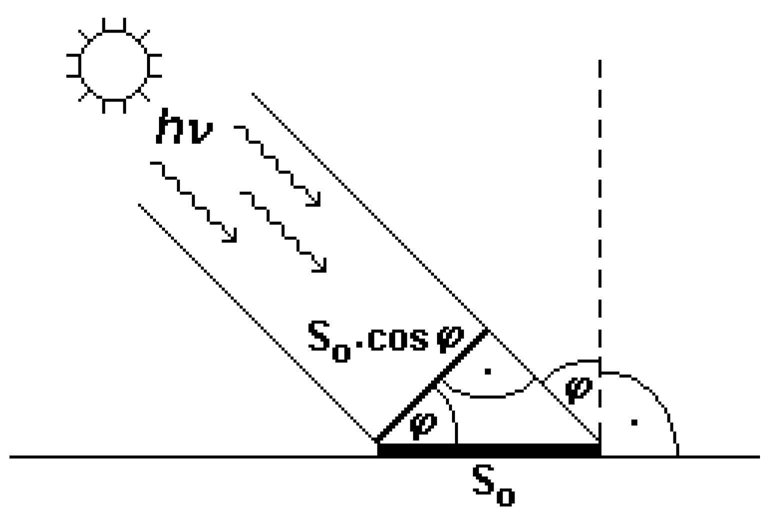
The theoretical calculation is as follows. The maximum radiation intensity absorbed by a plane perpendicular to the solar radiation is assumed to be . We assume an average day length (i.e., the sun above the horizon) of t = 12 hours = 43 200 s. Now, we compare a collector with an active area tracking the sun ideally with a fixed collector of the same size that is perpendicular to solar radiation at noon only.
a) For the fixed collector, the projection of its area onto the plane perpendicular to the solar radiation is
S =
S0 cos
φ, where
φ is the angle of incidence (see
Figure 1). During the day, the angle of incidence varies within the interval
. The angular velocity of the Sun in the sky is
. The differential of the incident energy is d
W =
I S d
t. Disregarding atmospheric effects, the energy absorbed by the collector area
S0 = 1 m
2 per day is as follows:
b) For a collector with a tracking device that follows the Sun perfectly, the energy absorbed by the collector of area
S0 = 1 m
2 per day can be obtained as follows (again neglecting the atmosphere effects):
If we could avoid atmospheric effects, the increase in incident solar energy (after multiplication by the efficiency and produced energy) would reach 57%. Under terrestrial conditions, after sunrise and before sunset, solar radiation must pass through a thick layer of atmosphere; hence, the intensity of radiation falling onto a plane perpendicular to the direction of the radiation is much lower than that at noon. In addition, the sun can be above the horizon for longer than 12 hours daily at higher geographic latitudes. The influence of diffuse circumsolar radiation and diffuse isotropic radiation also must be considered. The increased energy produced can reach a maximum of 40% on the Earth’s surface [
1,
4,
5,
7,
8,
9].
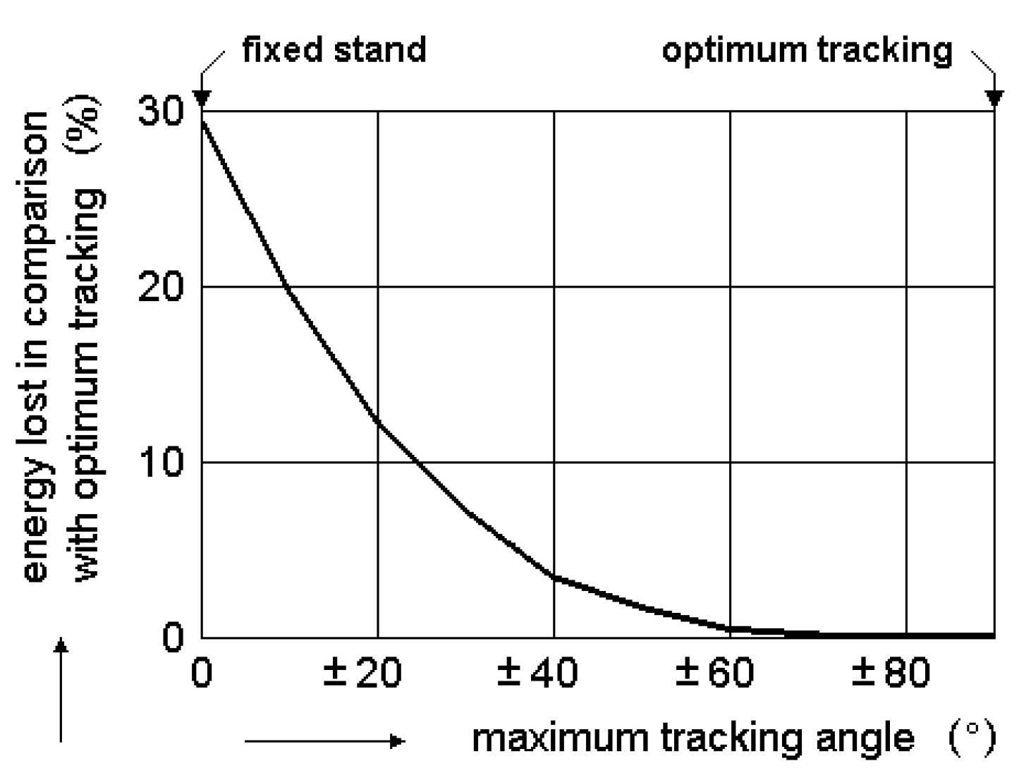
It is important to consider the system’s maximum angle of rotation. We noted that after sunrise and before sunset, the sun shines through a thick layer of the atmosphere. It is therefore obvious that, at the Earth’s surface, tracking a full ± 90° range of angles is unnecessary.
Figure 2 shows that sun tracking over a range of angles wider than ± 60° does not substantially influence the energy produced [
7,
10,
11,
12].
There are many designs of sun tracking devices in operation [
13,
14]. Some designs have been successfully applied in practice, whereas others have worked well in the laboratory [
15]. It is impossible to describe all the principles for sun tracking devices here. Solar trackers for flat plate PV panels and low-concentration (typically approximately 2x) flat plate PV systems (such as V-troughs,
Figure 3d) represent the vast majority of solar tracker applications [
16,[16,1[7]. On the other hand, the use of solar trackers for rare high
-concentration PV systems is more difficult, and a detailed description is beyond the scope of this article [
12].
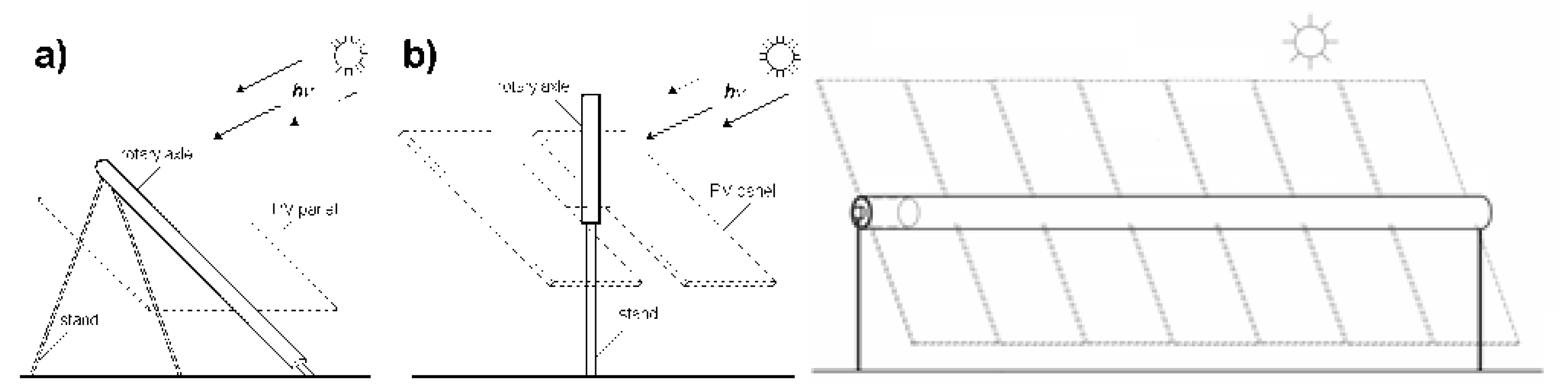
We describe several of the most important tracker principles, which are widely used in practice. There are also numerous variations of tracking stands; the common assembly with a polar rotary axle is shown in
Figure 3a. A less common variant with a vertical rotary axle is shown in
Figure 3b; this is suitable at higher geographic latitudes, where the changes in the Sun’s angle above the horizon are smaller [
18,
19].
Recently, horizontal axis trackers have become very popular.
Figure 3c
The vast majority of single-axis trackers follow the Sun in the east‒west direction (azimuth). Dual-axis (
Figure 3d, e) trackers are also available [
20,
21].
The energy gain of dual-axis trackers (typically approximately +35% is greater than that of single-axis trackers (typically approximately +30%) [
22,
23].
The dual-axis system tracks both the elevation and azimuth of the Sun [
24]. The dual-axis trackers are more complex (2 driving units are needed), more expensive and less reliable. Therefore, single-axis trackers have recently become much more common. Single-axis trackers will be discussed in more detail [
25,
26].
2. Trackers Based on the Clockwork Principle
Trackers can be based on the clockwork principle or on the principle of computer-controlled incremental servo drives with self-locking transmission [
27]. They can be very precise; they operate under weather conditions and can even operate in the dark. If computer-controlled incremental servo drives are used, one computer can control several tracking stands, and the motion of stands can be preprogrammed for the whole year. However, such systems are complicated and expensive, and moreover, the more complicated the system is, the greater its failure or breakdown probability. If the radiation concentration is low or zero, high-precision tracking is unnecessary. The potential of these expensive mechanisms is not fully understood. The cosine of the angle of incidence for angles
φ ≤ ± 5° differs only in the third decimal place (see theoretical calculation above).
3. Sensor-Based Trackers
3.1. Trackers Based on the Principles of Freon Evaporation and Condensation
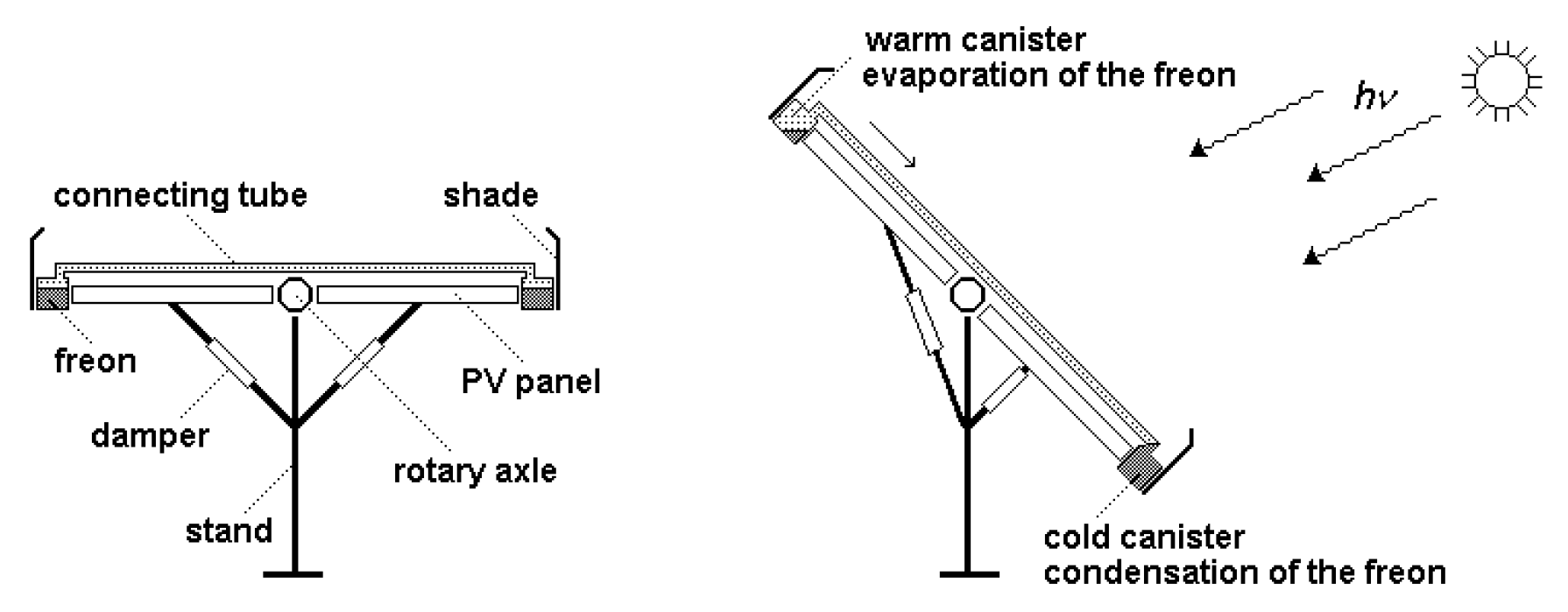
Trackers based on the principles of freon evaporation and condensation [
28,
29] are simple, but their tracking precision is inferior. Their scheme is shown in
Figure 4. Tanks with freons are attached to both sides of the levelled solar panel system. The tanks are connected by a tube and protected from direct solar radiation by screens. Direct solar radiation falls only on the tank that is on the side of the panel farther from the Sun and heats it. The freon evaporates, and its vapors condense in the cooler tank on the side of the panel closer to the Sun. This side becomes heavier, and the force of gravity pulls it downward. The whole solar PV system thus turns toward the Sun so that the angle of incidence of solar radiation on the PV panels decreases. Dampers are necessary to dampen impacts after tilting and vibrations are caused, e.g., by the wind. Such a system, operating on this principle and manufactured, can be seen in
Figure 4 [
30]
.
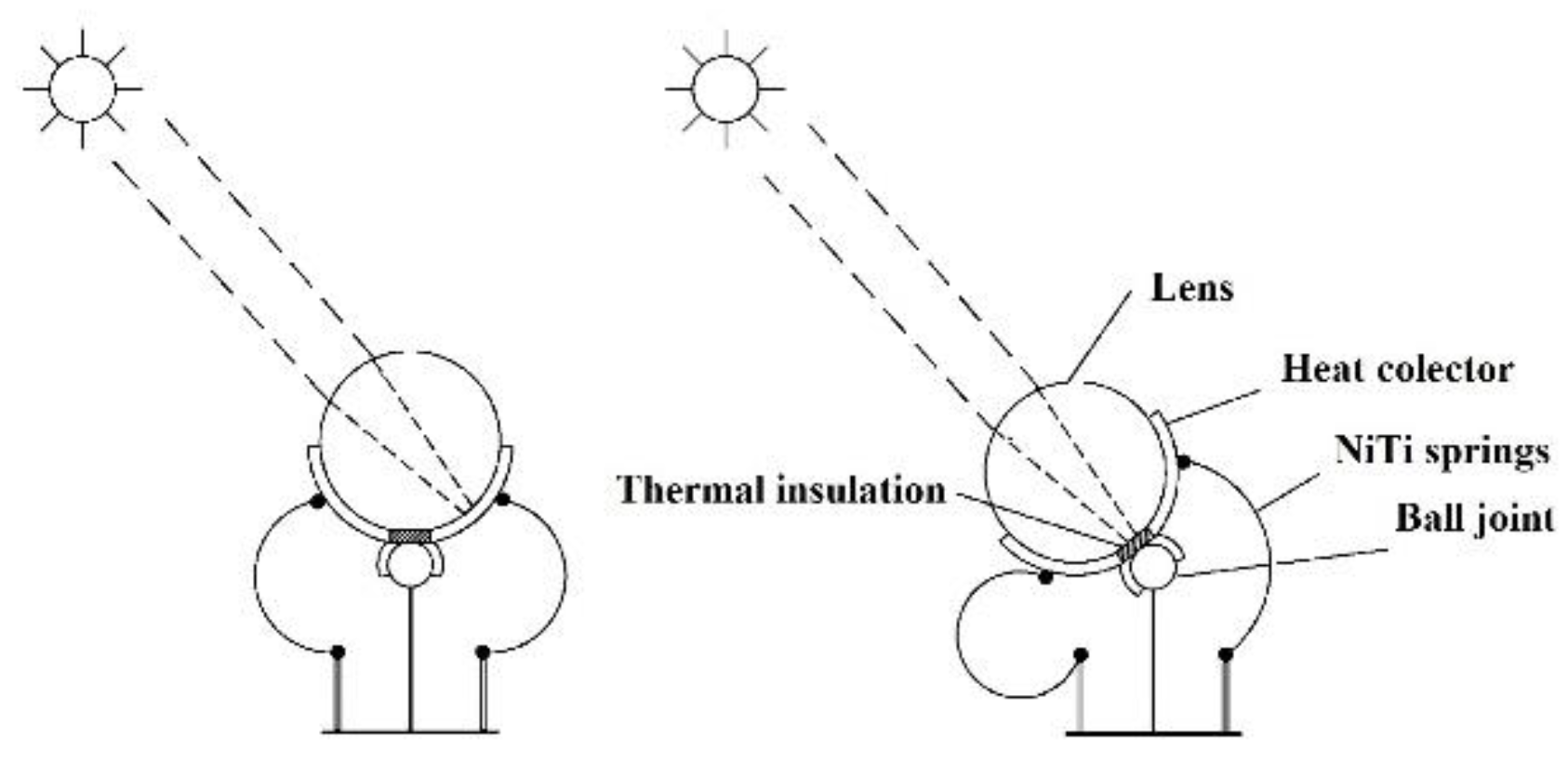
3.2. Trackers Based on the Principle of Springs Made of Shape-Memory Alloys
These trackers use the principle of shape-memory alloys, e.g., NiTi, CuZnAl, etc. Such alloys, if deformed, “remember” their original shape and, when reaching a certain so-called transformation temperature, return to it. Alloys with two-way shape memory return after the temperature is reduced to the deformed shape. If a component with one-way shape memory is used, an additional component—e.g., a classical spring—must be used to return the deformed shape of the alloy. These characteristics enable components made from these alloys to perform mechanical work when heated and cooled repeatedly. [
31]
Early design (
Figure 5) was presented at the Congress of the International Astronautical Federation (IAF) in Rome (1981), [
32].
There are various designs of trackers that are based on this principle. We present a concept [
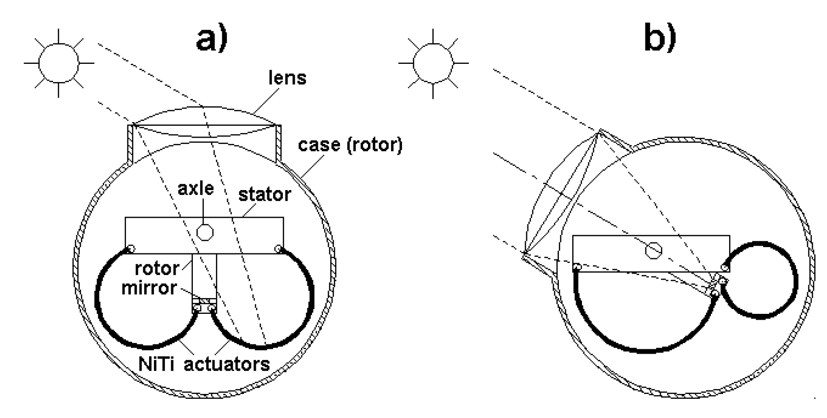
33] consisting of a stator, with a rotor rotationally connected to it and a lens to concentrate solar radiation. The actuators are springs made of nickel‒titanium-shaped memory alloy shaped like concave metal sheets placed at the lens focus. System operation is based on the fact that the actuators, placed in a case, are surface-finished to absorb solar radiation energy. One end is attached to the rotor, the other to the stator, making direct transfer of force from the actuator to the rotor possible. A convex lens mounted to the case is connected to the rotor, and its focus lies at the end of the actuator connected to the rotor. Connecting the lens to the rotor ensures that the optical axis of the lens is always more or less parallel to the incident radiation. Placing the lens focus at the end of the actuator automatically regulates the radiation energy falling on the actuators (feedback loop). The rotor is connected to the rotational axle of the tracking stand.
Figure 6a illustrates the device described in the outline. The cylindrical case with the lens fixed on it can be easily observed. The lens’s optical axis is oriented perpendicularly to the longitudinal axis of the case. The cylindrical case, with a U-shaped rotor mounted so that it can rotate, is placed on the part of the axle segment fixed to the rectangular stator, which can be seen inside the case. The actuators are made of two-way shape-memory alloy in the form of concave-shaped metal sheets and are placed inside the case at the focus of the achromatic lens. A mirror, installed between the actuators, protects them from overheating by reflecting excess solar radiation. At temperatures below the transformation temperature, the actuators deform into a concave shape, as shown in
Figure 6b.
Before sunrise, both actuators are in their initial positions (
Figure 6a). After sunrise, the achromatic lens concentrates solar radiation on one of the actuators. When the temperature of the actuator exceeds the transformation temperature, the component deforms until the focus of the achromatic lens shifts to the mirror, which then reflects the radiation back out of the case (
Figure 6b). Every shift in the position of the focus of the lens causes a deformation of the actuators such that the rotor is automatically set such that the mirror is at the lens focus. The tracking range over which the rotor can change its position is approximately Δ
φ ≈ 120° in this case.
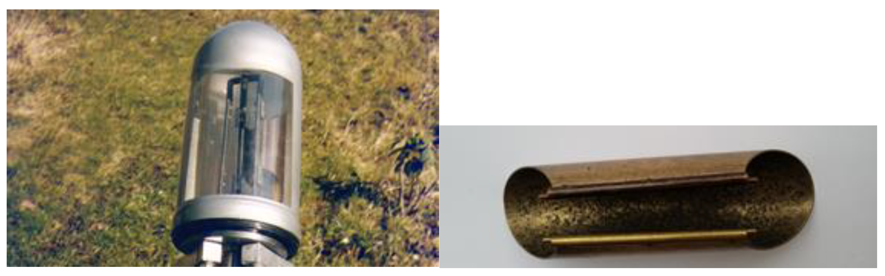
Figure 7a shows the real solar tracker head described above.
Figure 7b shows the details of the shape memory alloy spring [
31].
However, the design described has several disadvantages, including many advantages. First, it operates with very low efficiency. Moreover, at low winter temperatures, the device either fails completely, or the collector’s morning eastward orientation occurs only in late morning, when the sun is already high above the horizon. This is because in cold weather, it is more difficult for the actuators to reach the transformation temperature. If shape-memory alloys with a lower transformation temperature were used, the summer temperature would not decrease under this limit, causing summer failure, when the resulting power losses would be even greater than those in winter [
34].
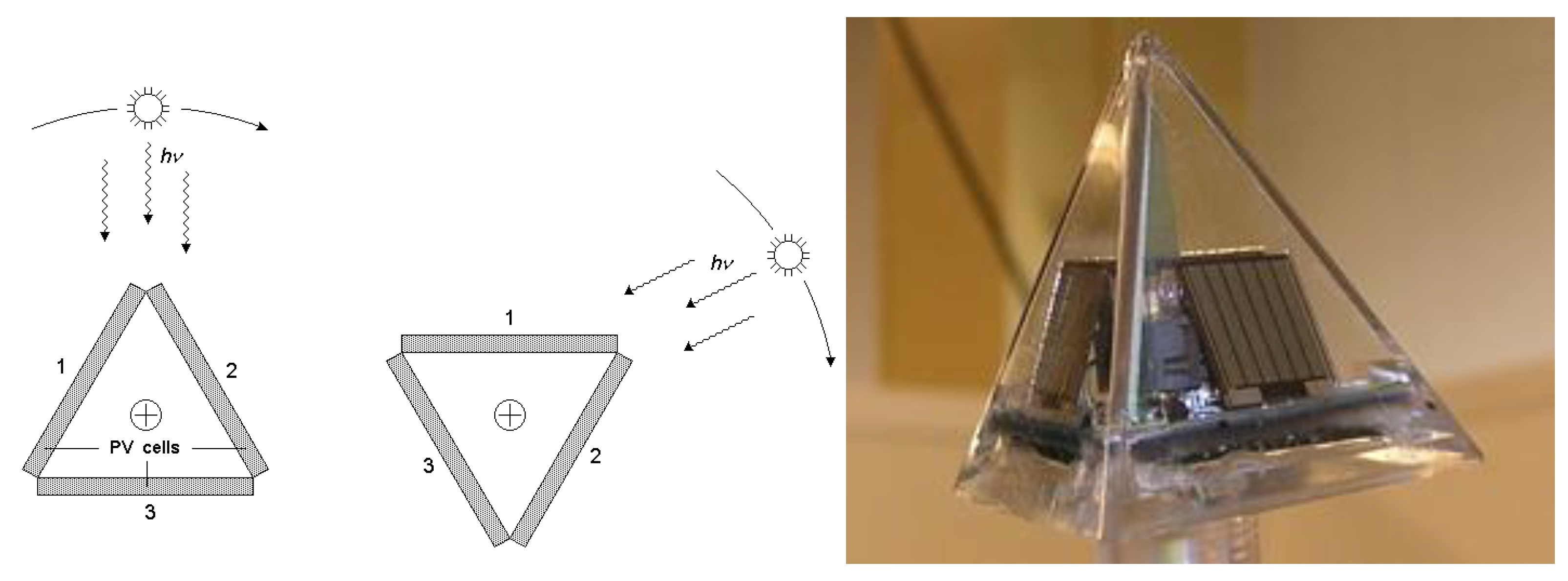
3.3. Solar Trackers Based on the Principle of Comparing the Differential Amount of Sunlight on Sensor PV Cells
Trackers consisting of pyramids of PV cells [
35,
36] compare signals (instantaneous energy outputs) from several small and slightly differently oriented PV cells. A schematic diagram of a tracker using three PV cells is shown in
Figure 8 a-b. The signals from the cells are evaluated and compared by a relatively complex electronic device that controls the drive moving the tracking stand. The electronic control positions the system so that the voltages from cells 1 and 2 are equal (i.e., the radiation intensity impinging on the two cells is equal), and the signal from cell 3 is lower. The pyramid orients itself so that the edge between cells 1 and 2 points toward the Sun. The Sun then lies in a plane with the same angle of inclination to both cells, i.e., in their symmetry plane. If two of these pyramid trackers are used, the orientation of the system can be controlled with respect to two axes, and the PV panels can be positioned precisely perpendicular to the direction of incident solar radiation.
The promise of relatively high-precision tracking favors these trackers, but conversely, the complexity of the electronic evaluation of signals from PV cells and its high price are clear disadvantages. More complex devices are also more prone to failure. Part of the energy produced by the PV panels may be used to power the drives moving with the stand; however, if an external energy supply was necessary, it would be another disadvantage. The details of a sensor with a pyramid of PV cells are given in
Figure 8b.
3.4. Trackers of the Traxle (TRackingAXLE) Type
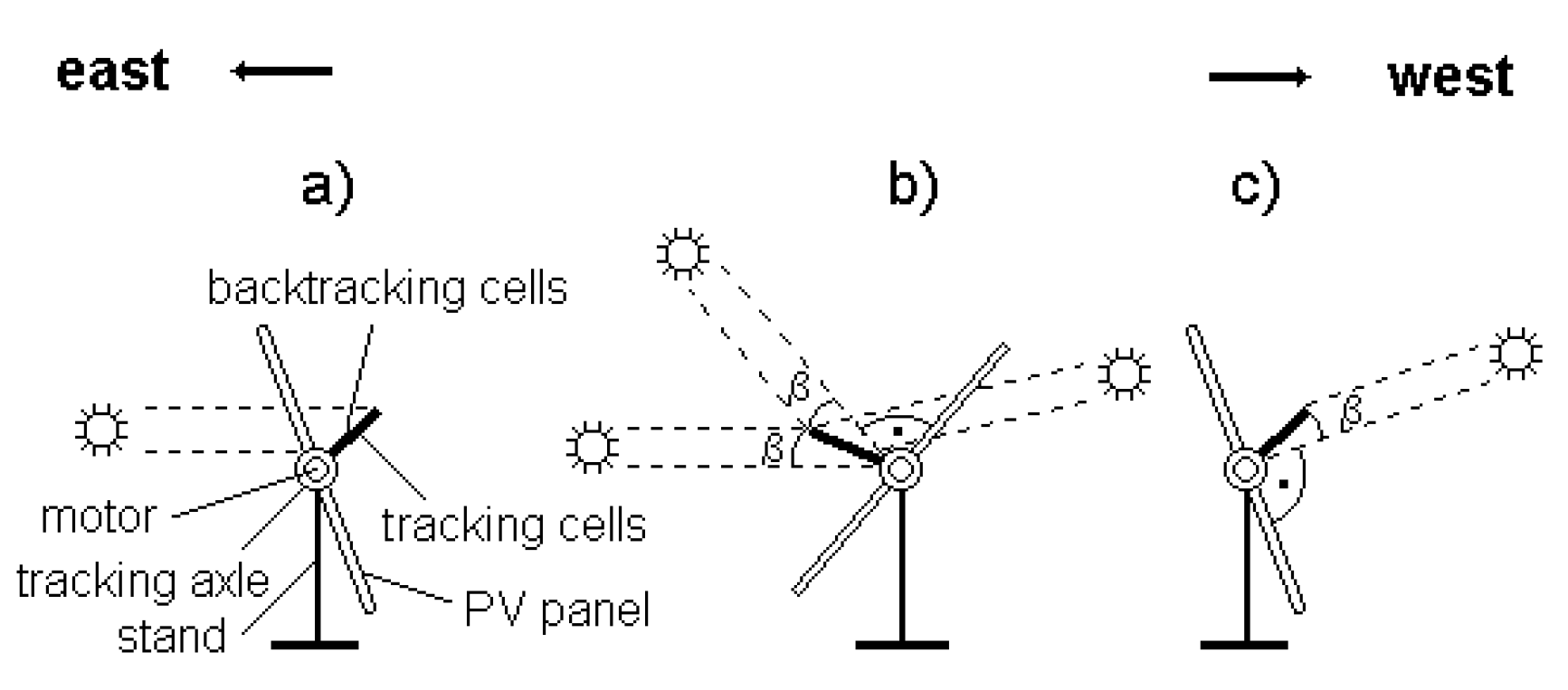
The disadvantages of the devices described above for the automatic orientation of solar energy collectors are solved in a new design. A schematic of the device is presented in
Figure 9 [
11,
37,
50]. The idea is to fix the control panel (with solar power cells for solar energy conversion to electric power) to the rotational axle. The panel consists of two sections turning 180° to each other (the main section westward and the auxiliary section eastward). The plane of the control panel is inclined eastward from the plane perpendicular to the solar energy collectors (and parallel to the rotational axis) by an angle of approximately
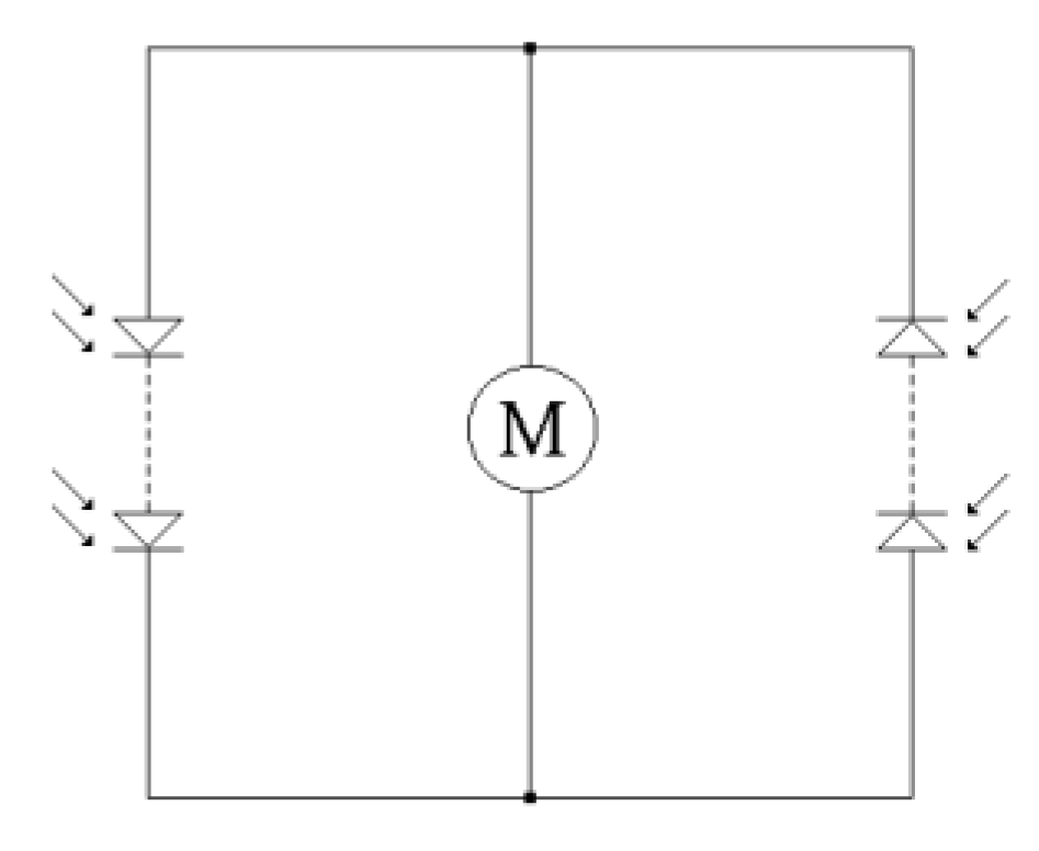
β ≈ 15÷20°. Both sections are anti-parallel connected to an electric motor fixed to the rotational axle of the device (see the wiring diagram in
Figure 10). The angle
β should be adjusted so that if the angle of incidence of solar radiation is
φ ≥ 90°-
β, the strength of the motor will be insufficient to orient the device, but if the angle of incidence of solar radiation is
φ ≤ 90°-
β, the strength of the motor will be sufficient to orient the device. Thus, if the control panel is illuminated by solar radiation from any side with an angle of incidence
φ ≤ 90°-
β, the signal from this side will be stronger than that from the opposite side, and the energy produced by the control panel drives the motor to turn the system to increase the angle of incidence with respect to the control panel. Rotation stops when the angle of incidence is
φ = 90°-
β because the power of the motor is now below the threshold necessary for reorienting the system. As the angle of incidence with respect to the control panel decreases because of the movement of the Sun in the sky, the system moves to increase it again. On a sunny day, the system turns in a stepwise incremental manner (rather than continuously) from east to west. Recalling that the projection of the PV panel onto a plane perpendicular to the solar radiation is directly proportional to the cosine of the angle of incidence, we can see that the difference in both areas is smaller than 4 per mile. The influence of this difference on the amount of energy produced is obviously negligible. This device uses negative feedback; the power from the control panel drives the motor; and the system’s mechanical resistance and environmental resistance act against this motive force.
Δ
φ ≤ 30° under predominantly diffuse solar radiation. In the limiting case, assuming a fully clouded sky with only diffuse radiation, no sun tracking is necessary [
40].
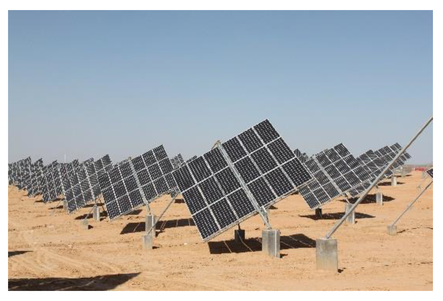
Direct connection of the electric motor to solar cells without any further electronic circuits makes the device simpler and thus more reliable. This arrangement has considerably lower production costs, a simpler and more compact design, and higher efficiency than other devices for orienting planar solar collectors, as described above. Furthermore, it operates without any other power source because solar energy is also used to power its drive. Real existing PV systems with tracking stands of the Traxle type can be seen in
Figure 11.
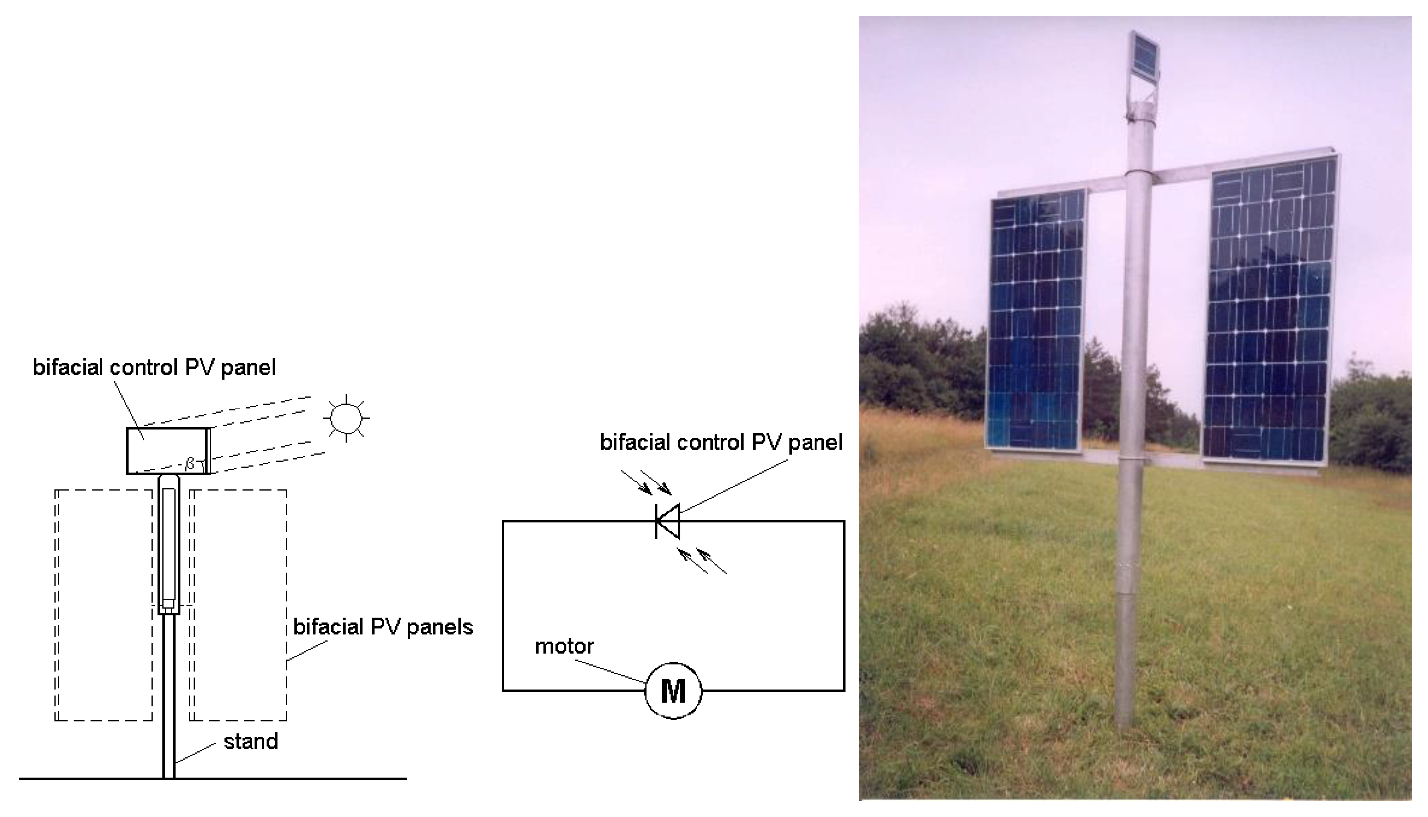
A variant of the Traxle tracker capable of 360° tracking also exists for applications within polar circles or in space [
41]. In this case, the rotational axle and PV panels are oriented vertically; an epicyclic gear is used instead of a screw gear, and the control panel is placed perpendicular to the solar energy collectors and is not inclined at an angle β. Bifacial PV panels must be used: if they are cloudy for longer periods of time and then the sun appears, the system may turn its front or rear sides sunwards, depending on the immediate position of the Sun relative to the PV system. A schematic diagram of such a configuration is presented in
Figure 12. The electronic circuitry is even simpler than that described above. An actual system is depicted in
Figure 12a.
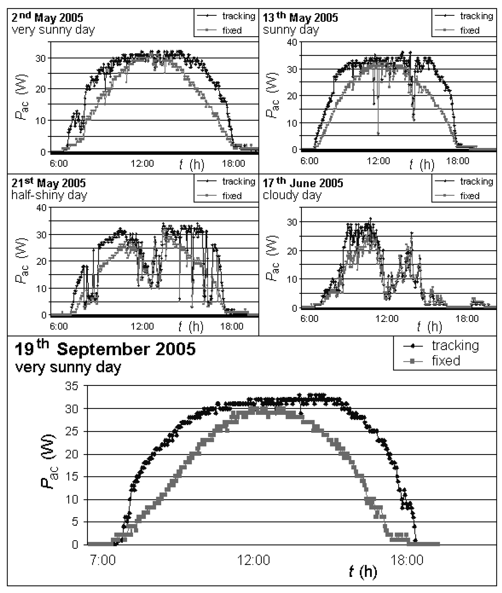
Figure 13 gives examples of actual measurements made by us, for the dependence of instantaneous output on time, for the conditions of Prague 6–Suchdol (50° northern latitude) throughout the year 2005. We compared two identical panels with a maximum output
Pmax= 40 W
p. One was mounted to a Traxle
-type automatic tracking stand, and the other was mounted to a fixed stand. The city of Bragg is located at longitude 15 degrees east. During the summer, the sun reaches its highest point in the sky at approximately 1 P.M. As already stated, the amount of energy produced corresponds to the area below the curve in the diagram. The incremental improvement in energy production on sunny days due to the tracking stand is considerable. On 2 May 2005, the improvement was 30%. The largest improvement, 39%, was observed on 19 September 2005. Understandably, the difference is smaller on cloudy days. Moreover, the energy produced on sunny days is greater in the afternoon under Central European conditions, since in the morning, the atmosphere usually contains more water vapor, which absorbs close infrared radiation. Hence, the maximum of the curve for the movable panel occurs at approximately 2 P.M.
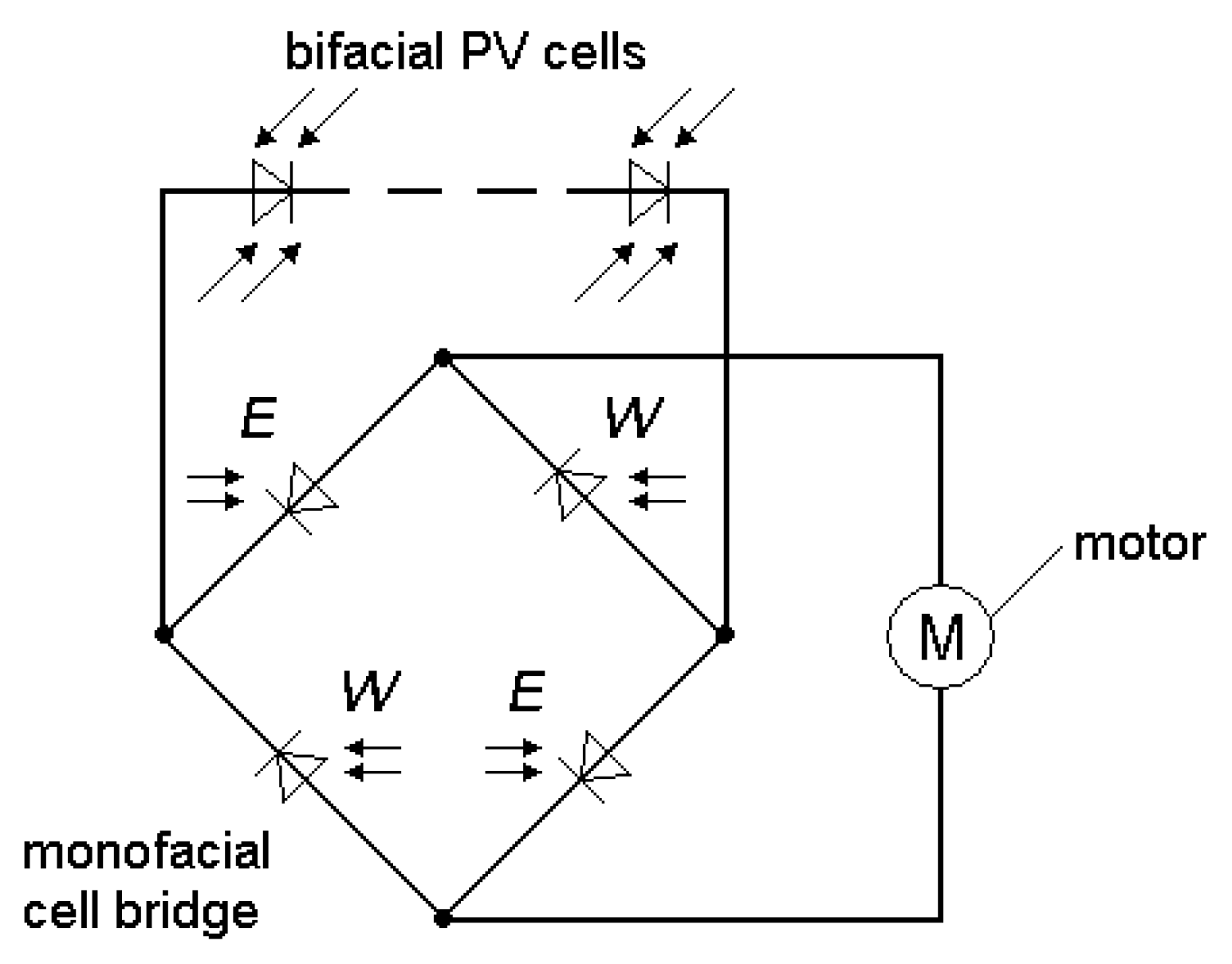
For low-concentration systems with geometrical concentration ratios less than 5x, a more accurate tracker was developed. The polar axis solar tracker uses bifacial cells and only a few monofacial cells that steer the tracker. In the electronic bridge structure (
Figure 14).
The tracker can detect the sun anytime from sunrise until sunset. All the PV cells, both bifacial and monofacial, are laminated in a single glass/glass panel, whereas in the preceding design [
37,
42], 2 separate glass/TPT PV panels in an antiparallel arrangement were used. Therefore, the new design is more compact. A simple electronic circuit is used to improve the performance of the monofacial cells.
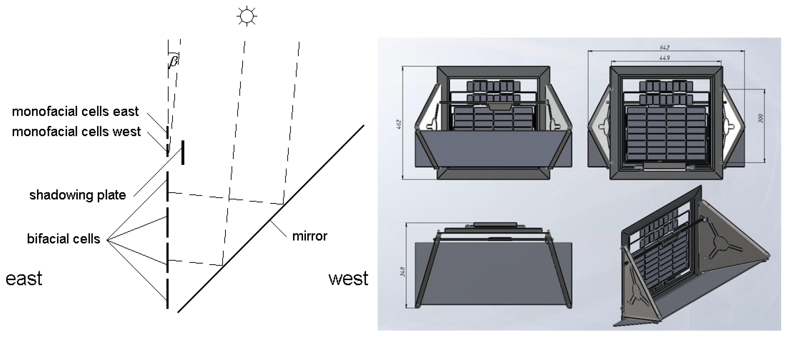
However, for low-concentration PV (LCPV) systems [
12,
43], the tracking accuracy of + 5 angular degrees is not sufficient. As the typical angle between the tracking PV panel and sun rays is approximately 7–10 degrees, the PV panel can supply a small amount of power only to the driving motor for accurate tracking. The solution is to attach a mirror to the tracking panel [
44,
45]. The mirror is tilted 45 degrees westward from the tracking panel. A scheme of the panel/mirror arrangement is shown in
Figure 15a-b.
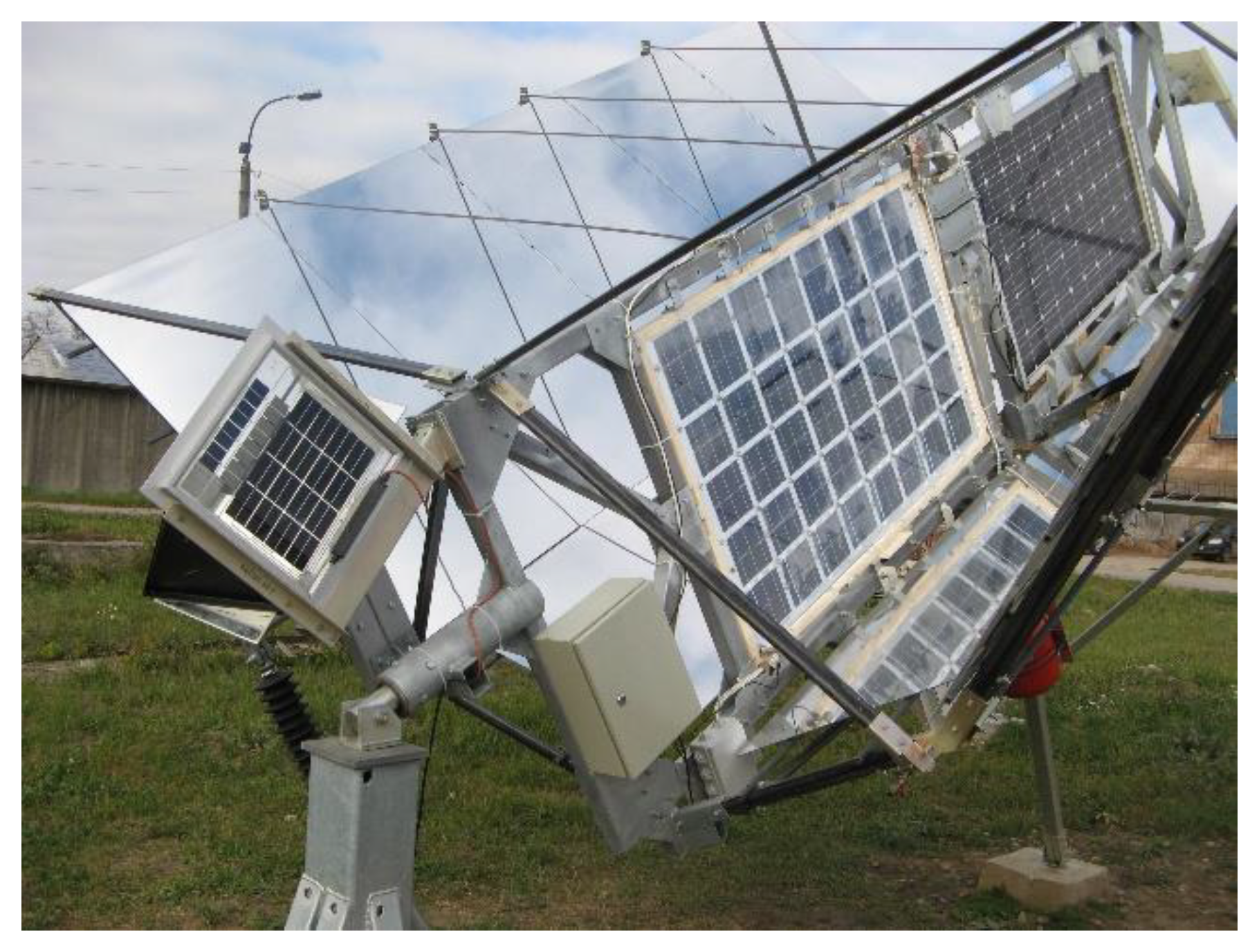
The innovative tracker fixed to the 2 kW pseudo parabolic concentrator [
43,
46,
47] is shown in
Figure 16.
Temperature-resistant PV panels with polysiloxane encapsulants [
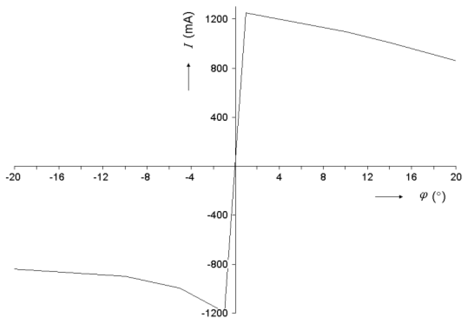
48] have to be used. The tracking electric motor needs a current of approximately 200 mA to move the PV array. The mirror provides enough power to the PV panel for tracking with an accuracy of 1 degree (
Figure 17).
4. Mutual Shading of Tracking Stands
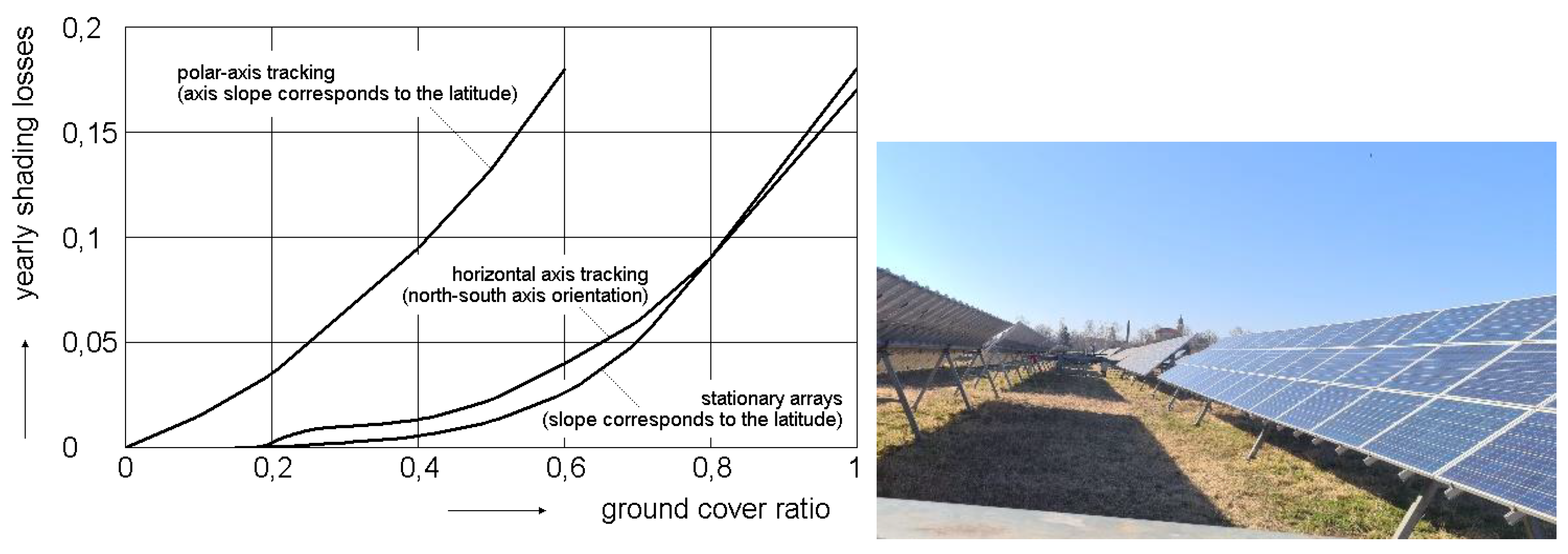
If we install a large PV system consisting of a whole array of stands with PV panels, the mutual shading of the stands becomes a very important parameter to consider during installation. In European conditions, systems with tracking stands require an area approximately 3 times larger than those with fixed stands (
Figure 18a) [
7,
49,
50]. In countries with lower land prices, this is not a major problem. In Europe, where land prices are very high, this becomes a very important factor. The horizontal axis trackers with GCRs similar to those of fixed stands can help, but the annual energy gain of horizontal axis trackers in locations far from the equator (Europe, North America, etc.) is only approximately +10%.
The horizontal axis trackers yield the best results in the equatorial area between the tropics. The GCR is similar to that of fixed stands, and the annual energy gain is approximately +30% compared with that of fixed stands [
51]. Moreover, the mechanical designs of fixed and tracking PV panel support structures are very similar when horizontal trackers are used. Therefore, the main price difference between fixed support structures and horizontal axis tracking support structures is very low, at approximately 3%. This is caused by the (linear/slew) actuator price and (polymer) bearing price. The sensor price is negligible. In solar tracking systems, PV panels are exposed to relatively high average temperatures and high levels of average ultraviolet radiation. Therefore, for operation in demanding/hot climates, the best quality PV panels should be used. This is very important because there are many reports on the reduced real lifetime of new PV panels, especially in demanding/tropical climate regions [
52].
Recently, the majority of tracking PV power plants have used horizontal axis arrangements.
5. Driving Units
The typical driving units are represented as follows:
- (a)
Linear actuators (either ball screws or ACMEs)
Figure 19
- (b)
- (c)
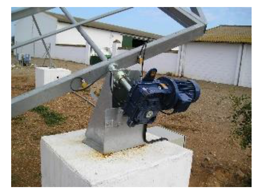
Other driving units, such as the worm gear motor shown in
Figure 21, etc.
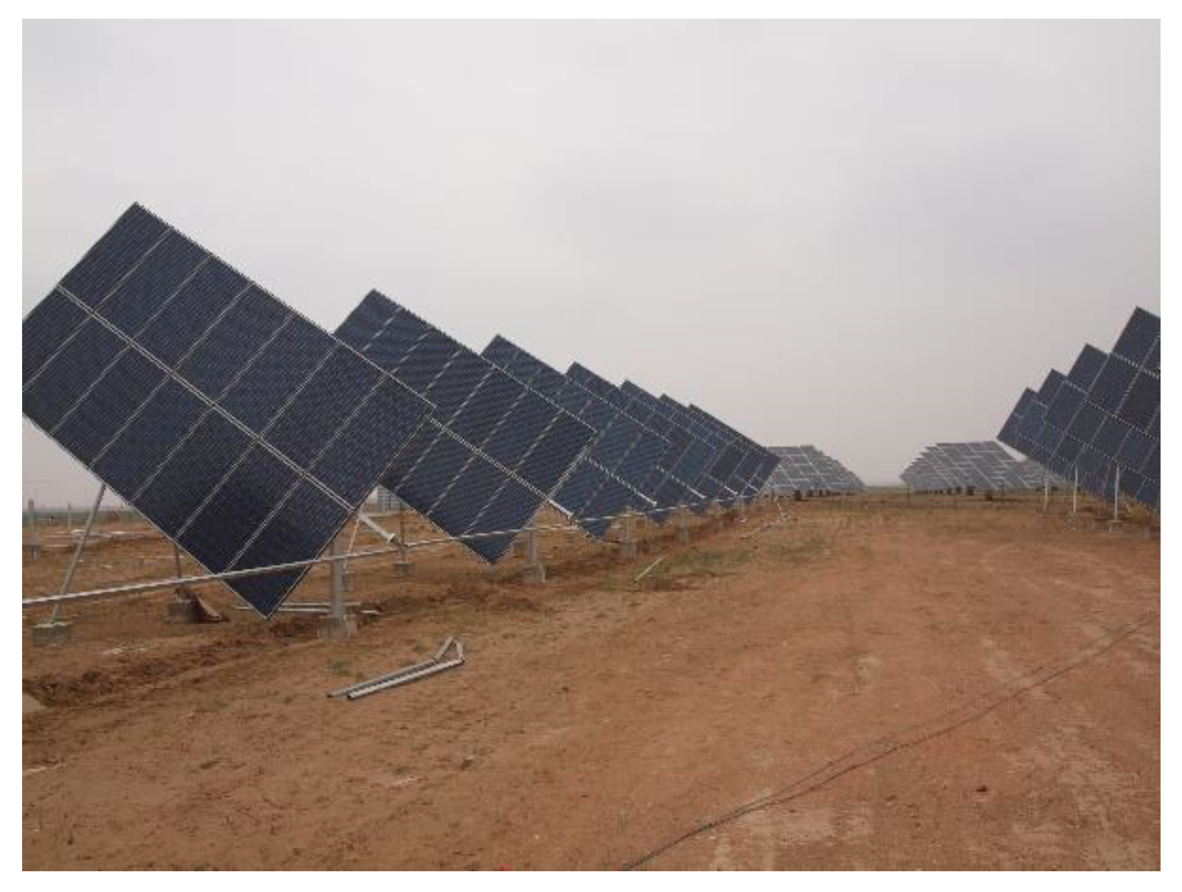
Small tracking PV systems, which are typically 10 kW to 1 MW in size, usually have many individual tracking support structures where each separate tracking support structure is equipped with its own driving unit (
Figure 11).
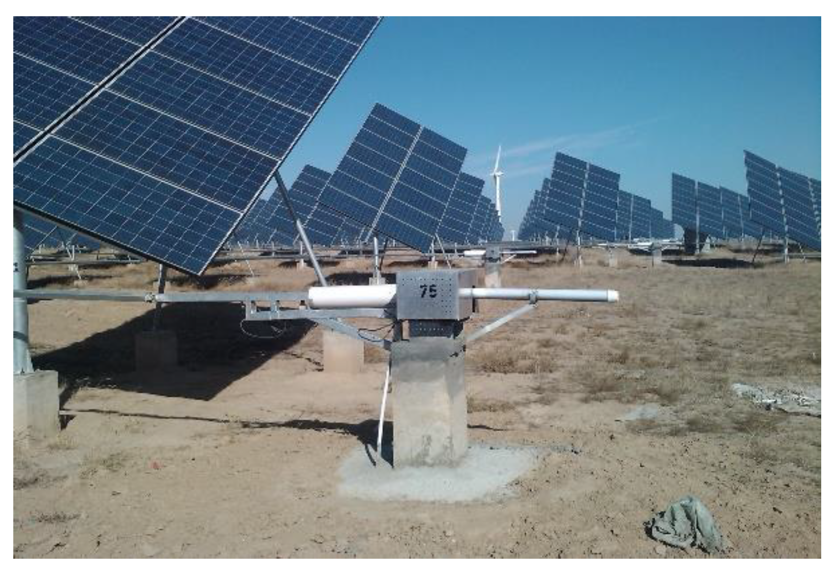
For large PV power plants typically above 1 MW, a number of tracking support structures share a single powerful driving unit. The tracking support structures are mechanically interconnected and coupled to a single diving unit.
This scheme is possible for arrays of polar axis tracking support structures (
Figure 22 and
Figure 23).
6. Reliability and Serviceability of Driving Units
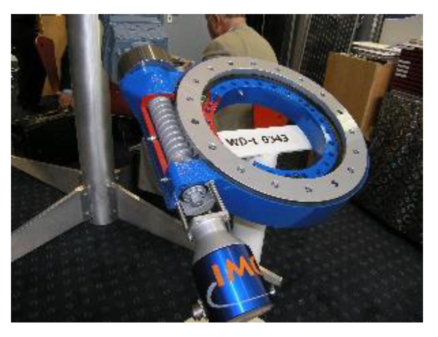
The driving units are the most exposed parts of the solar tracker.
As the lifetime of driving units is short compared with the lifetime of the PV power plant, serviceability is very important. For example, the estimated mean time between duty failures (MTBF) of a linear actuator is approximately 40,000 hours. The calculated MTBF depends on many conditions, such as the duty cycle, load, climate, and environment. However, the real MTBF is usually shorter than the calculated MTBF.
Many tracker designs enable replacement of the driving unit only by dismantling the PV array. Therefore, it is very expensive. This is typical for slew drives, as the slew drive is usually part of the load-carrying structure.
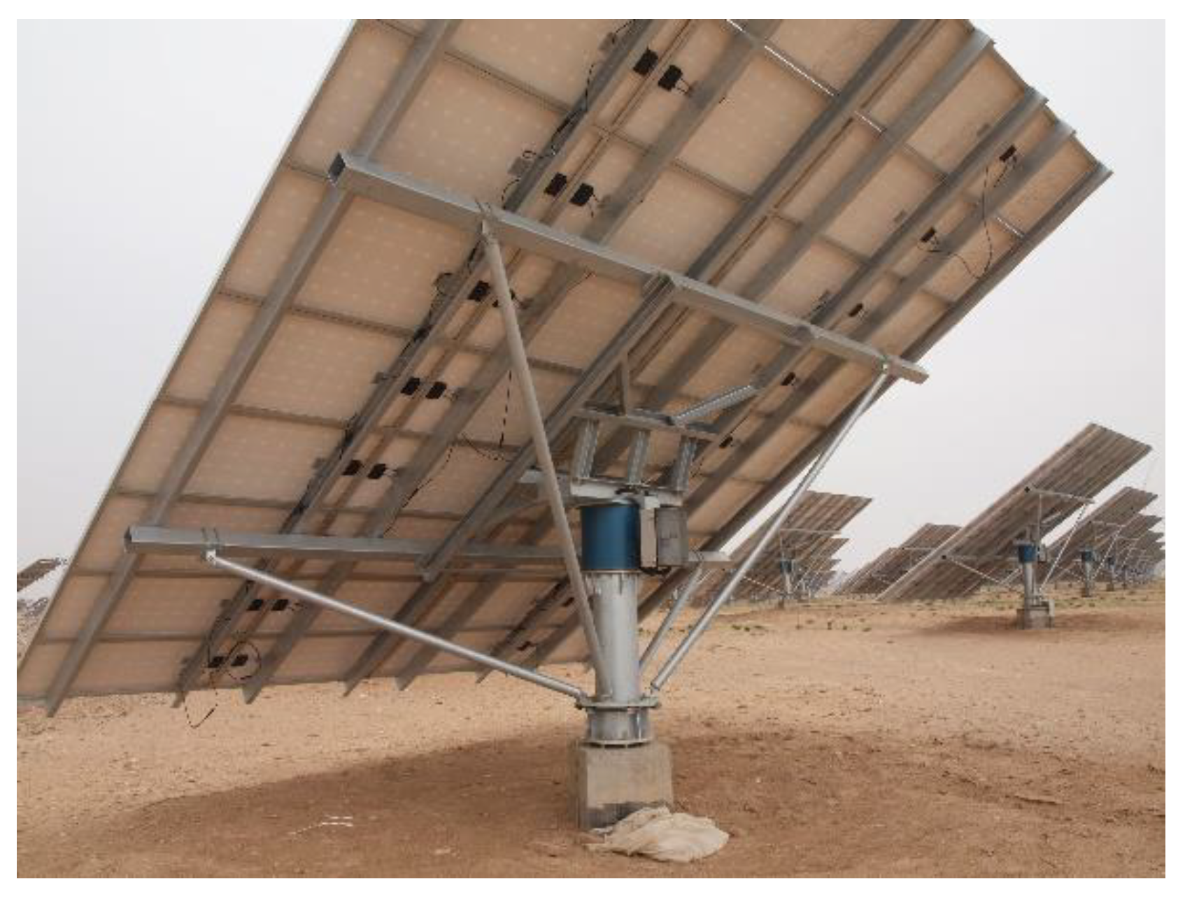
Figure 24 shows the vertical axis tracker, where the slew drive is fixed directly to the tracking axle.
The slew drive bearing is part of the tracking axle bearing. The replacement is more difficult, as the complete 20–30 kW PV panel array is caried by the slew drive. Dismantling of the PV array is needed to replace the broken slew drive.
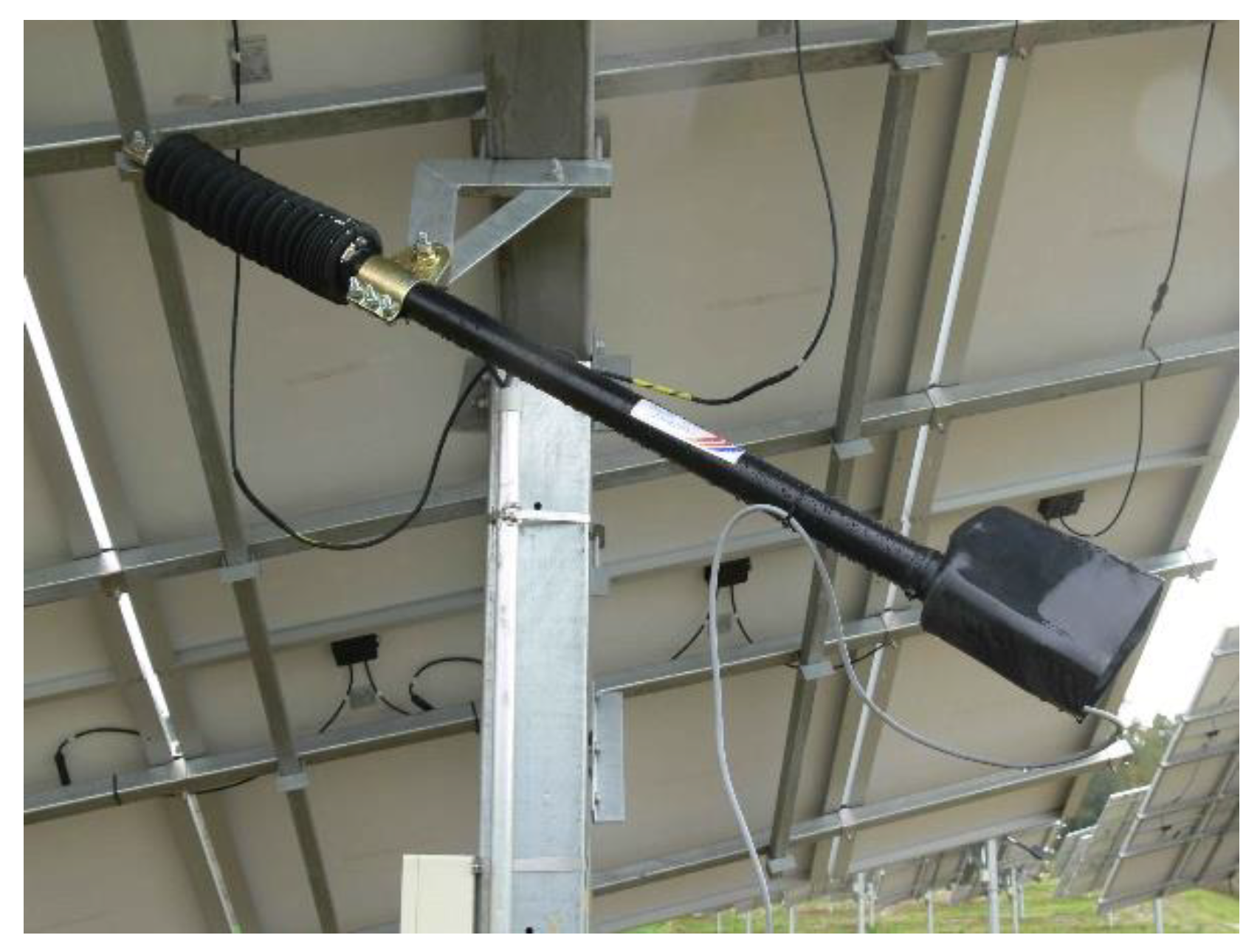
Linear actuators can mostly be more easily replaced. However, even among linear actuator arrangements, substantial differences can exist. While
Figure 25b shows a linear actuator fixed on the top of the solar tracker axle,
Figure 25a shows a linear actuator arranged at the bottom side of the axle. Of course, it is much easier to maintain or replace the linear actuator at the bottom.
7. Conclusions
There has been substantial development in the design of single-axis solar trackers for flat plate photovoltaic panels within the last 40 years. Despite the recent substantial reduction in PV panel prices, horizontal single-axis trackers remain profitable solutions in regions between the tropics because of the high ground cover ratio (GCR) and annual energy gain above +30%. In solar tracking systems, PV panels are exposed to higher average temperatures and higher average levels of ultraviolet radiation. Therefore, for operation in demanding/hot climates, the best quality PV panels should be used. This is very important because there are many reports on the reduced real lifetime of new PV panels in demanding/tropical climate regions.
References
- Awasthi, A. , Shukla A.K., Murali Manohar S.R., Dondariya C., Shukla K.N., Porwal D., Richhariya G., Review on sun tracking technology in solar PV system. Energy Reports 2020, 6, 392–405. [Google Scholar] [CrossRef]
- Zhao, D. , Xu E., Wang Z., Yu Q., Xu L., Zhu L., Influences of installation and tracking errors on the optical performance of a solar parabolic trough collector. Renewable Energy 2016, 94, 197–212. [Google Scholar] [CrossRef]
- Nsengiyumva, W. , Chen S.G., Hu L., Chen X., Recent advancements and challenges in Solar Tracking Systems (STS): A review. Renewable & Sustainable Energy Reviews 2018, 81, 250–279. [Google Scholar] [CrossRef]
- Hession, P.J. , Bonwick, W.J., Experience with a sun tracker system. Solar Energy 1984, 32, 3–11. [Google Scholar] [CrossRef]
- Baltas, P. , Tortoreli, M., Russell, P.E., Evaluation of power output for fixed and step tracking photovoltaic arrays. Solar Energy 1986, 37, 147–163. [Google Scholar] [CrossRef]
- Poulek, V. , Libra, M., A Very Simple Solar Tracker for Space and Terrestrial Applications. Solar Energy Materials and Solar Cells 2000, 60, 99–103. [Google Scholar] [CrossRef]
- Gordon, J.M. , Wenger, H.J., Central-station solar photovoltaic systems: field layout, tracker and array geometry sensitivity studies. Solar Energy 1991, 46, 211–217. [Google Scholar] [CrossRef]
- AL-Rousan, N. , Isa, N.A.M., Desa, M.K.M., Advances in solar photovoltaic tracking systems: a review. Renewable & Sustainable Energy Reviews 2018, 82, 2548–2569. [Google Scholar] [CrossRef]
- Hafez, A.Z. , Increasing the efficiency of photovoltaic systems. LAMBERT Academic Publishing; 2015, ISBN: 978-3-659-34467-1.
- Lorenzo, E. , Perez, M., Ezpeleta, A., Acedo, J., Design of tracking photovoltaic systems with a single vertical axis. Progress in Photovoltaics: Res. Appl. 2002, 10, 533–543. [Google Scholar] [CrossRef]
- Libra, M. , Poulek, V., Bifacial PV Modules in Solar Trackers and Concentrators, a New Approach to Supplying Power in Agriculture, chapter in the book “Physical Methods in Agriculture, Approach to Precision and Quality”, Kluwer Academic/Plenum Publishers, New York, 2002, 83-104, ISBN 0-306-47430-1.
- Luque A, Andreev V., Concentrator Photovoltaics. Springer, Berlin, Heidelberg, 2007, ISBN: 978-3-540-68796-2. [CrossRef]
- Hafez, A.Z. Yousef, A.M., Harag, N.M., Solar tracking systems: Technologies and trackers drive types - A review. Renewable and Sustainable Energy Reviews 2018, 91, 754–782. [Google Scholar] [CrossRef]
- Panagopoulos, A. A, Chalkiadakis, G., Jennings, N.R., Toward optimal solar tracking: a dynamic programming approach. Proc. of the 29th AAAI Conference on Artificial Inteligence, -30, 2015, Austin, USA, 695–701. Book Series: AAAI Conference on Artificial Intelligence. 25 January.
- Roong, A.S.C. , Chong S.H., Laboratory-scale single axis solar tracking system: Design and implementation. International Journal of Power Electronics and Drive Systems 2016, 7, 254–264. [Google Scholar] [CrossRef]
- Neagoe, M,, Visa, I. , Burduhos, B.G., Moldovan, M.D., Thermal load based adaptive tracking for flat plate solar collectors. Energy Procedia 2014, 48, 1401–1411. [Google Scholar] [CrossRef]
- Maia, C.B. , Ferreira, A.G., Hanriot, S.M., Evaluation of a tracking flat-plate solar collector in Brazil. Applied Thermal Engineering 2014, 73, 953–962. [Google Scholar] [CrossRef]
- Miloudi, L. , Acheli, D., Chaib, A., Solar tracking with photovoltaic panel. Energy Procedia 2013, 42, 103–112. [Google Scholar] [CrossRef]
- Zogbi, R. , Laplaze, D., Design and construction of a sun tracker. Solar Energy 1984, 33, 369–372. [Google Scholar] [CrossRef]
- Li, L. , Li, H., Xu, Q., Huang, W., Performance analysis of Azimuth Tracking Fixed Mirror Solar Concentrator. Renewable Energy 2015, 75, 722–732. [Google Scholar] [CrossRef]
- Huang, F. , Li, L., Huang W., Optical performance of an azimuth tracking linear Fresnel solar concentrator. Solar Energy 2014, 108, 1–12. [Google Scholar] [CrossRef]
- Theebhan, M. , Long, C.Y., Tiong, T.T., Design and development of a solar thermal collector with single axis solar tracking mechanism. MATEC Web of Conferences 2016, 78, 01002. [Google Scholar] [CrossRef]
- Gaafar, A.E. , Zobaa, A.F., Economical design of a two-axis tracking system for solar collectors. 5th IET International Conference on Renewable Power Generation, RPG 2016, -23, 2016, London, U.K. 21 September. [CrossRef]
- Tanaka, H. , Nakatake, Y., One step azimuth tracking tilted-wick solar still with a vertical flat plate reflector. Desalination 2009, 235, 1–8. [Google Scholar] [CrossRef]
- Huld, T. , Cebecauer, T., Suri, M., Dunlop, E.D., Analysis of one-axis tracking strategies for PV systems in Europe. Progres in Photovoltaics: Res. Appl. 2010, 18, 183–194. [Google Scholar] [CrossRef]
- Fathabadi, H. , Novel high accurate sensorless dual-axis solar tracking system controlled by the maximum power point tracking unit of photovoltaic systems. Applied Energy 2016, 173, 448–459. [Google Scholar] [CrossRef]
- Radajewski, W. Water-driven solar tracking mechanism. Energy in Agriculture 1987, 6, 167–176. [Google Scholar] [CrossRef]
- Baer, U.S. 1979; 4.
- Ch. W. Geer, U.S. patent 2,999,943, 1961.
- Photovoltaic Tracking Racks. Zomeworks Corp. 2014 [online], Available from: http://www.zomeworks.com/photovoltaic-tracking-racks/, Accessed 14-01-2023.
- Poulek, V. , Testing the new solar tracker with shape memory alloy actors. Proc. IEEE FIRST WORLD CONFERENCE ON PHOTOVOLTAIC ENERGY CONVERSION/CONFERENCE RECORD OF THE TWENTY FOURTH IEEE PHOTOVOLTAIC SPECIALISTS CONFERENCE, -9, 1994, Waikoloa, HI, USA, 1131-1133, vol.1, Book Series: IEEE Photovoltaic Specialists Conference, ISBN: 0-7803-1460-3. 5 December.
- 6 September 1981; -01.
- Poulek, V. , New low cost solar tracker. Solar Energy Materials and Solar Cells 1994, 33, 287–291. [Google Scholar] [CrossRef]
- Eldin, S.A.S. , Abd-Elhady, M.S., Kandil, H.A., Feasibility of solar tracking systems for PV panels in hot and cold regions. Renewable Energy 2016, 85, 228–233. [Google Scholar] [CrossRef]
- Haywood a kol., U.S. patent 4,082,947, 1978.
- Avarand, S. , Pirmoradian, M., Solar tracking system with momentary tracking based on operational amplifiers in order to be used in photovoltaic panels for following the sun. Bull La Société R Des Sci Liège 2016, 85, 269–277. [Google Scholar] [CrossRef]
- Poulek, V. , Libra, M., New Solar Tracker. Solar Energy Materials and Solar Cells 1998, 51, 113–120. [Google Scholar] [CrossRef]
- Wang, J. , Zhang, J., Cui, Y., Bi, X., Design and implementation of PLC-based automatic sun tracking system for parabolic trough solar concentrator. MATEC Web Conferences 2016, 77, 06006. [Google Scholar] [CrossRef]
- Sallaberry, F. , Pujol-Nadal, R., Larcher, M., Rittmann-Frank, M.H., Direct tracking error characterization on a single-axis solar tracker. Energy Conversion and Management 2015, 105, 1281–1290. [Google Scholar] [CrossRef]
- Kelly, N.A. , Gibson, T.L., Improved photovoltaic energy output for cloudy conditions with a solar tracking system. Solar Energy 2009, 83, 2092–2102. [Google Scholar] [CrossRef]
- Poulek, V. , Libra M. 60.
- H. S. Rauschenbach, The principles and technology of photovoltaic energy conversion, Litton Educational Publishing, Inc. 1980.
- Poulek, V. , Khudysh, A., Libra, M., Self powered solar tracker for Low Concentration PV (LCPV) systems. Solar Energy 2016, 127, 109–112. [Google Scholar] [CrossRef]
- Drury, E. , Lopez, A., Denholm, P., Margolis, R., Relative performance of tracking versus fixed tilt photovoltaic systems in the USA. Progress in Photovoltaics: Res. Appl. 2014, 22, 1302–1315. [Google Scholar] [CrossRef]
- Khudysh, A. , 2010. Russian Patent No. 2.426.
- Poulek, V. , Khudysh, A., Libra, M., Innovative low concentration PV systems with bifacial solar panels. Solar Energy 2015, 120, 113–116. [Google Scholar] [CrossRef]
- Gama, A. , Larbes, C., Malek, A., Yettou, F., Adouane, B., Design and realization of a novel sun tracking system with absorber displacement for parabolic trough collectors. Journal of Renewable and Sustainable Energy 2013, 5, 033108. [Google Scholar] [CrossRef]
- Poulek, V. , Dang M-Q., Libra M., Beránek V., Šafránková J., PV Panel With Integrated Lithium Accumulators For BAPV Applications – One Year Thermal Evaluation. IEEE Journal of Photovoltaics 2020, 10, 150–152. [Google Scholar] [CrossRef]
- Moradi, H. , Abtahi, A., Messenger, R., Annual performance comparison between tracking and fixed photovoltaic arrays. Proc. IEEE 43rd PHOTOVOLTAIC SPECIALISTS CONFERENCE (PVSC), -10, 2016, Portland, OR, USA, 3179-3183, Book Series: IEEE Photovoltaic Specialists Conference. 5 June.
- Mahendran M, Ong HL, Lee GC, Thanikaikumaran K. An experimental comparison study between single - axis tracking and fixed photovoltaic solar panel efficiency and power output: Case study in east coast Malaysia. Sustain. Dev. 2013.
- Poulek, V. , 2000. Apparatus for Orientation of Solar Radiation Collectors. US Pat. No. 6.089.224.
- Poulek, V. , Tyukhov I., Beranek V. On site renovation of degraded PV panels – cost and environmental effective technology. Solar Energy 2023, 263, 111956. [Google Scholar] [CrossRef]
Figure 1.
Projection of the collector plane into the plane perpendicular to the radiation direction.
Figure 1.
Projection of the collector plane into the plane perpendicular to the radiation direction.
Figure 2.
Losses of energy produced compared with the optimal tracking ± 90°.
Figure 2.
Losses of energy produced compared with the optimal tracking ± 90°.
Figure 3.
(a-b) Arrangement of tracking stands a) Polar axis, b) vertical axis. c Arrangement of the horizontal axis tracking stand.
Figure 3.
(a-b) Arrangement of tracking stands a) Polar axis, b) vertical axis. c Arrangement of the horizontal axis tracking stand.
Figure 4.
Scheme of the sun tracker on the principles of freon evaporation and condensation.
Figure 4.
Scheme of the sun tracker on the principles of freon evaporation and condensation.
Figure 5.
Scheme of the solar tracker using shape memory NiTi alloy springs.
Figure 5.
Scheme of the solar tracker using shape memory NiTi alloy springs.
Figure 6.
a-b Scheme of a tracker on the principle of shape-memory alloys.
Figure 6.
a-b Scheme of a tracker on the principle of shape-memory alloys.
Figure 7.
a Solar tracker using CuZnAl-shaped memory springs. b Details of the CuZnAl shape memory spring.
Figure 7.
a Solar tracker using CuZnAl-shaped memory springs. b Details of the CuZnAl shape memory spring.
Figure 8.
a Scheme of a tracker based on the principle of comparison of the differential amount of sunlight on sensor PV cells. b Details of the sunlight on the sensor with PV cells made by Deger.
Figure 8.
a Scheme of a tracker based on the principle of comparison of the differential amount of sunlight on sensor PV cells. b Details of the sunlight on the sensor with PV cells made by Deger.
Figure 9.
Traxle-type sun tracker scheme.
Figure 9.
Traxle-type sun tracker scheme.
Figure 10.
Wiring diagram.
Figure 10.
Wiring diagram.
Figure 11.
Traxle polar axis trackers at a 10-MW PV power plant in China (Ningxia).
Figure 11.
Traxle polar axis trackers at a 10-MW PV power plant in China (Ningxia).
Figure 12.
Configuration scheme of the 360°-tracking Traxle tracker for applications within a polar circle. a. The 360° Traxle tracker.
Figure 12.
Configuration scheme of the 360°-tracking Traxle tracker for applications within a polar circle. a. The 360° Traxle tracker.
Figure 13.
Time dependence of the instantaneous output measured during selected days for two identical PV panels, one with a fixed stand and the other with a tracking stand.
Figure 13.
Time dependence of the instantaneous output measured during selected days for two identical PV panels, one with a fixed stand and the other with a tracking stand.
Figure 14.
Wiring diagram of the solar tracker using both bifacial and monofacial solar cells.
Figure 14.
Wiring diagram of the solar tracker using both bifacial and monofacial solar cells.
Figure 15.
a Cross-sectional scheme of tracking Panel with the concentrating mirror.
b Drawing of the design according to the scheme of
Figure 15a.
Figure 15.
a Cross-sectional scheme of tracking Panel with the concentrating mirror.
b Drawing of the design according to the scheme of
Figure 15a.
Figure 16.
Pseudo parabolic concentrator with a bifacial tracking panel and mirror. The linear actuator is fixed at the bottom side of the axle (easy access).
Figure 16.
Pseudo parabolic concentrator with a bifacial tracking panel and mirror. The linear actuator is fixed at the bottom side of the axle (easy access).
Figure 17.
Current generated by the tracking panel in the range of +20 angular degrees.
Figure 17.
Current generated by the tracking panel in the range of +20 angular degrees.
Figure 18.
a Dependence of annual relative losses due to shading on the relative ground coverage in Central Europe. b Horizontal axis of the 1.7-MW tracking array powered by the 4 linear actuator Czech.
Figure 18.
a Dependence of annual relative losses due to shading on the relative ground coverage in Central Europe. b Horizontal axis of the 1.7-MW tracking array powered by the 4 linear actuator Czech.
Figure 19.
Linear actuator.
Figure 19.
Linear actuator.
Figure 20.
Slew drive actuator.
Figure 20.
Slew drive actuator.
Figure 21.
Worm gear motor actuator.
Figure 21.
Worm gear motor actuator.
Figure 22.
Array of polar axis trackers mechanically interconnected to a single driving unit.
Figure 22.
Array of polar axis trackers mechanically interconnected to a single driving unit.
Figure 23.
Linear actuator driving an array of polar axis solar trackers - China (Ningxia).
Figure 23.
Linear actuator driving an array of polar axis solar trackers - China (Ningxia).
Figure 24.
Slew drive carrying a complete solar tracker.
Figure 24.
Slew drive carrying a complete solar tracker.
Figure 25.
a, b Linear actuator at the bottom and top sides of the polar axis tracker.
Figure 25.
a, b Linear actuator at the bottom and top sides of the polar axis tracker.
|
Disclaimer/Publisher’s Note: The statements, opinions and data contained in all publications are solely those of the individual author(s) and contributor(s) and not of MDPI and/or the editor(s). MDPI and/or the editor(s) disclaim responsibility for any injury to people or property resulting from any ideas, methods, instructions or products referred to in the content. |
© 2025 by the authors. Licensee MDPI, Basel, Switzerland. This article is an open access article distributed under the terms and conditions of the Creative Commons Attribution (CC BY) license (http://creativecommons.org/licenses/by/4.0/).