Submitted:
18 August 2025
Posted:
19 August 2025
You are already at the latest version
Abstract
The goal of writing this paper is to study the complexity of Formula 1 (F1) car which is integrated machine involving multiple areas of science and engineering. This paper is intended to study mechanical design, aerodynamics, materials science and electronics into a single high-performance system of F1. This information was gathered for study purpose and can be referred by students to link engineering with its real-life applications in cars.
Keywords:
Formula 1
; F1
; multidisciplinary
; structure
; aerodynamics
; materials
; power unit
; sustainability
; transmission
; steering controls
; tyres
; cross-disciplinary
Introduction:
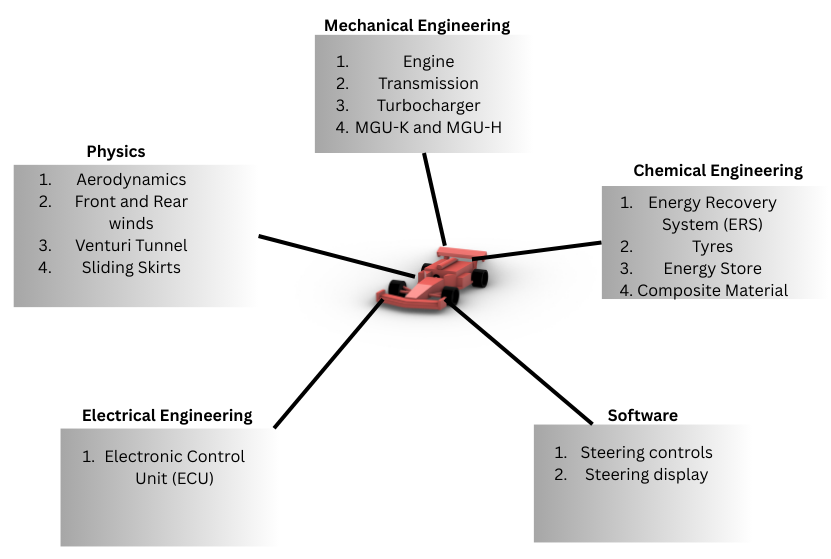
F1 represents a prime example of multi-disciplinary fields integrating mechanical designs, electronics and advanced components to offer a perfect combination of power, precision and sustainability. This paper investigates the role of lightweight composite materials, aerodynamic design, drivetrain in enhancing speed, safety and efficiency in terms of fuel consumption.
Material:
Material used for F1 is a critical determinant of overall chassis rigidity, strength integrity and driver safety. Progressive advancements in material utility for F1 has enabled to engineer a lightweight car for enhanced on-track performance and reduced inertial overload.
In 1981, McLaren F1 team pioneered Fibre Reinforced Composite Material to achieve a ideal strength-weight ratio and is stronger and lightweight compared to conventional materials like Steel and Aluminium. In contemporary, about 85% of F1 teams utilise carbon fibre composite material. Composite material consists of several materials such as polyacrylonitrile, rayon, pitch which are undergone through advanced processes such as layering or extrusion.
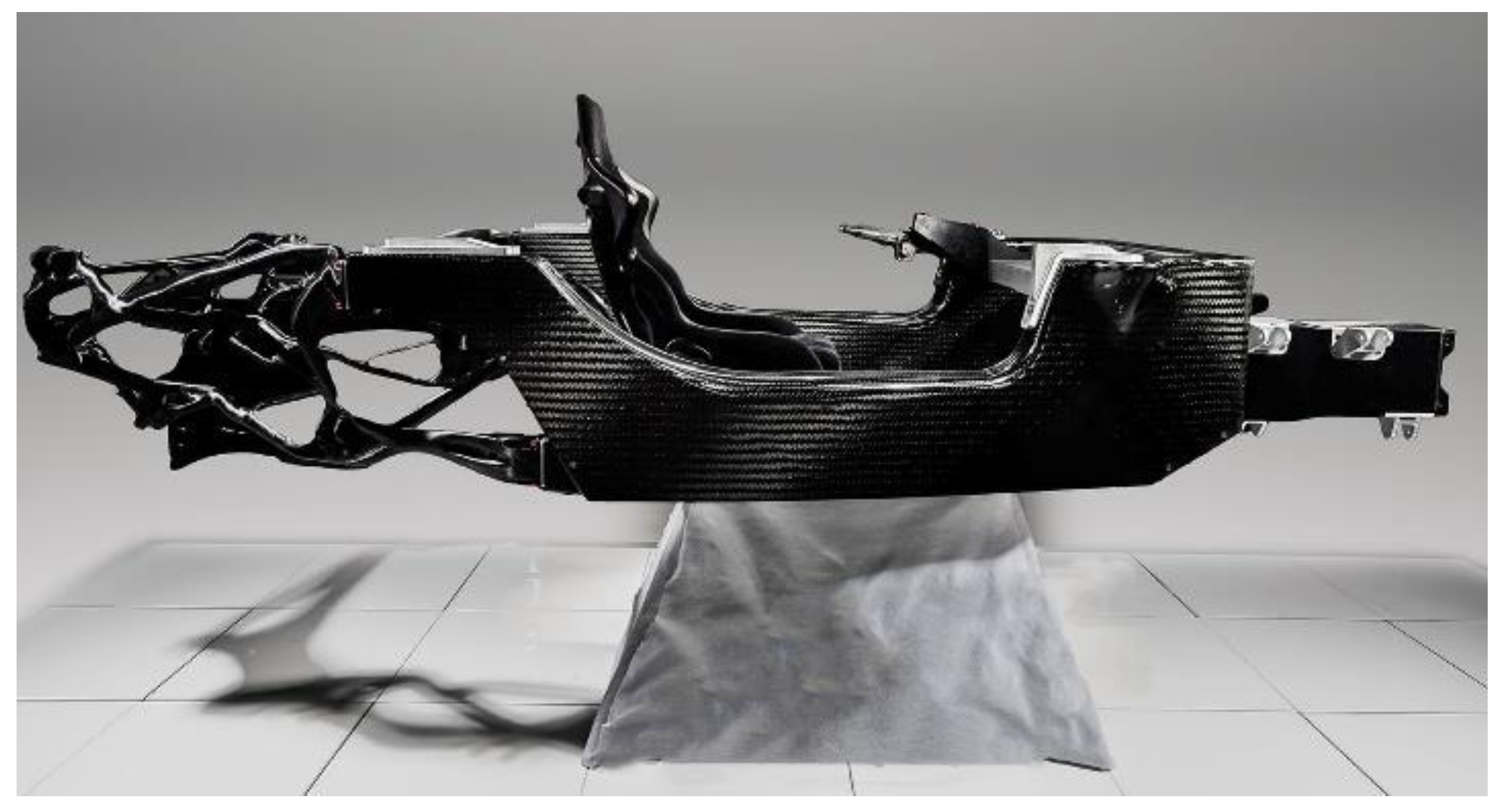
Figure 1.
F1 chassis made of Carbon-fibre-reinforced-polymer (CFRP) [source: THEDRIVE].
Other crucial materials used in F1 consists of Aramide, Zylon to achieve a high safety rating for F1 body, drivers suits and helmets. Aramide is a strong with high tensile strength (3.6 GPa) and a high modulus (130 GPa) is utilised in F1 front wings as it can resist high energy debris strikes and strong aerodynamic fluid pressure. It is also used in internal structuring of F1 cockpit.
Zylon is another highly durable poly(p-phenylene-2,6-benzobisoxazole) fibre offering high tensile strength (5.8 GPa) and high modulus (270 GPa) generally used in wheel tethers which are cable-like structures which prevents intrusion of chassis and suspension at high velocities. It maintains overall integrity structure and wheels. Zylon is also used in F1 cockpits for enhancing driver’s safety by absorbing shock impacts during racing. Zylon with its composite matrix, provides energy and stress dissipation mechanism and minimizes mass volume for aerodynamic efficiency.
Figure 2.
F1 car wheel tether made up of Zylon.
F1 engines are mostly made up of aluminium alloys, steel and titanium alloys for its mechanical components. To be precise, aluminium is used in cylinders and pistons due to its high tensile strength (700MPa) to endure high G-forces, intense vibrations; steel alloys are used in camshaft and crankshafts due to its high strength-weight ratio; whereas titanium is used in other parts such as engine input and output valves to optimise strength and its high resistance to stress and heat. These materials even though heavier are used as FIA (Fédération Internationale de l'Automobile) or (International Federation of Automobile) has regulated the use of composite materials. The main reason is CFRP when damaged, fails or ruptures suddenly leading to catastrophic consequences. But aluminium, on the other hand, deforms before failing giving enough time to warn controllers about the issue.
F1 tyres utilise magnesium alloys due to their exceptional lightweight and high heat dissipation potential assisting brake ducts to cool faster triggering enhanced on-track wheel grip, car body stability and faster lap times.
Structure and Aerodynamics:
Structure Information:
Current dimensions of a F1 car- wheelbase ~3.6m, length ~5.63m, width ~2m, height ~0.95m.
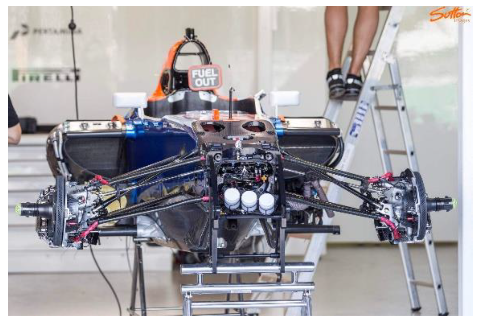
F1 chassis is designed as a CFRP monocoque chassis providing a highly durable body framework during racing. Moreover, it has a streamline shape to improve aerodynamics along with safety. Generally, F1 follows 45% front and 55% rear weight distribution pattern which lowers the centre of gravity for enhanced stability at high speeds and cornering. [9]
Driver’s seating posture is structured with highly reclined geometry to optimise ergonomic comfort and biomechanical performance. This seating configuration facilitates driver’s ease to access steer controls to boost their confidence. Moreover, the reclined posture augments kinesthetic feedback enabling drivers to receive and tune with the car to modify car dynamics in real time. The seats and headrests are built using advanced shock- absorbing materials ensuring driver safety and cervical stability especially during car rollover scenario.
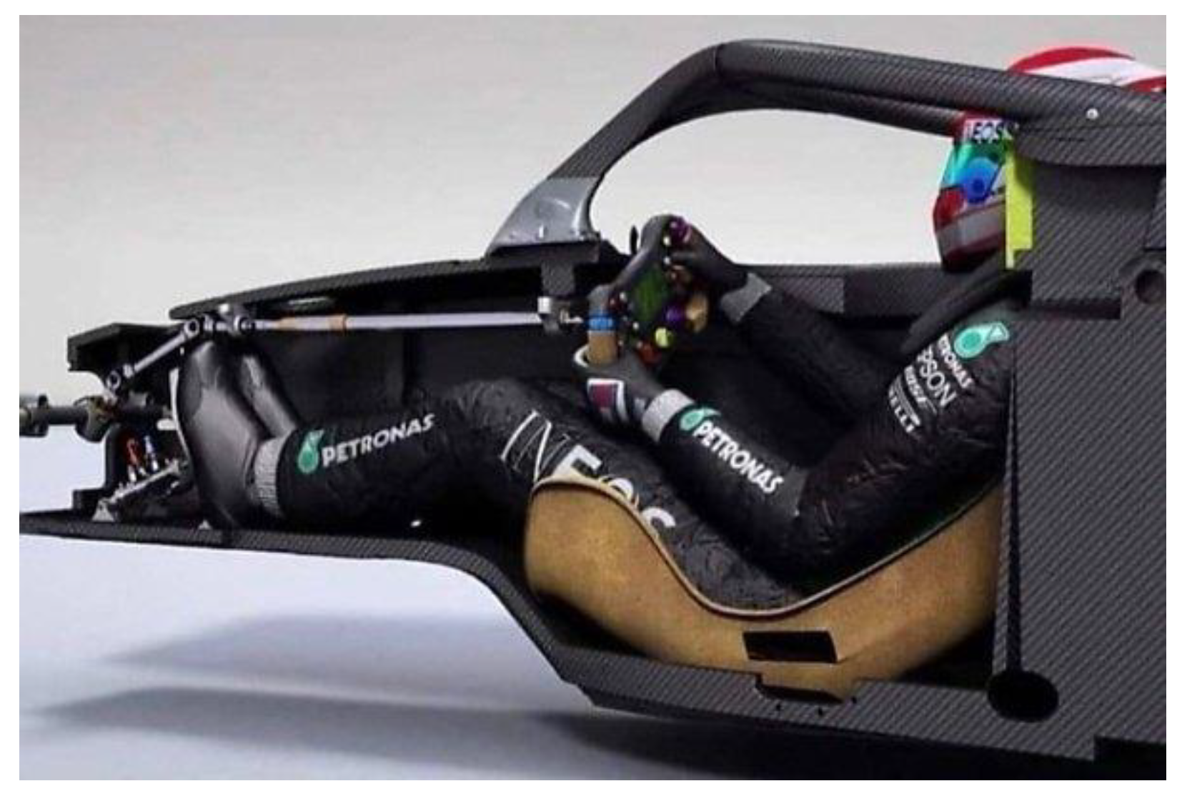
Figure 3.
F1 driver’s seating position [].
Aerodynamics:
Wings (Front and rear), spoilers, venturi tunnels along with sliding skirts are vital for achieving superior aerodynamics in F1.
Figure 4.
Wind simulation on F1 car [].
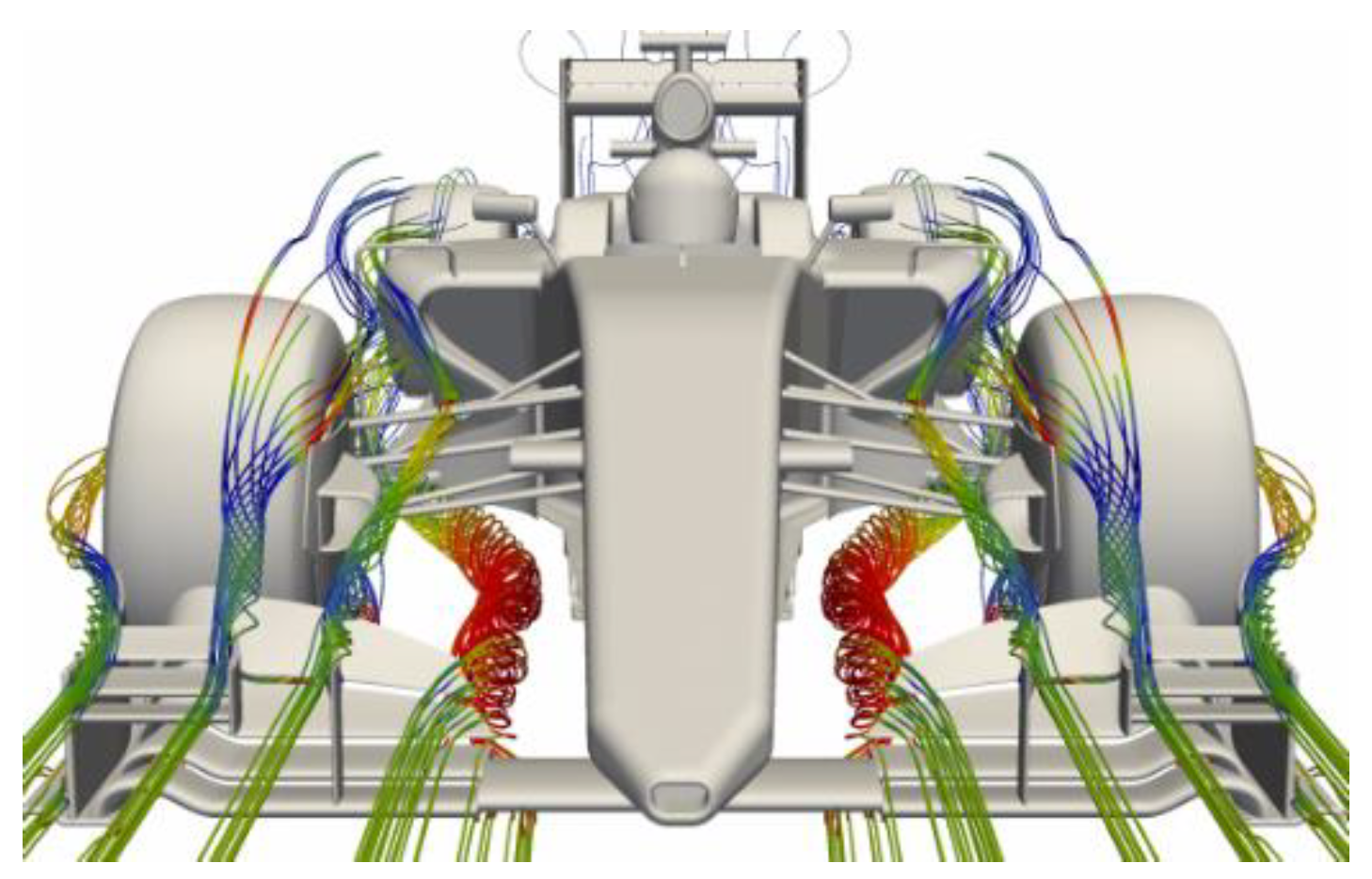
Functions:
- 1)
- Wings and spoilers: Enhances the aerodynamic efficiency through smooth air to produce controlled pressure difference in higher and lower car surfaces to trigger negative lift to generate high contact forces between wheels and ground for achieving high lateral speeds. With increased downward force, it enables high cornering grip and stability. This concept is based on Bernoulli’s Theorem. Front wings are engineered in thick and streamlined geometry to generate more downward lift enhance tyre-surface grip. Due to rear placement of engine, same thickness of rear wings would lead uncontrolled weight distribution with unbalanced downward force leading to lifting up of the car from front. As a result, rear wings are designed to be thin in order to maintain centre of gravity through proper weight and force distribution in front and rear end for optimum car performance and stability. [2,7]
- 2)
- Venturi Tunnels: Help in providing low pressure area beneath the car body triggering enhanced downward lift as in case of aeroplane wings.
- 3)
- Sliding skirts: Optimises the effect of venturi tunnels by packing up space between car side body and track to prevent air from escaping venturi tunnels. This provides efficient fluid flow through venturi tunnels to enhance aerodynamics.
Power Unit:

Table 1.
Engine Specifications.
| Specification | Power Unit | |||
| Traditional (1980-2000) | Traditional (2000-2003) | Pre-Modern (2007-2008) | Modern (2013-2024) | |
| Configuration | 3.5 litre Naturally Aspirated V12 | 3 litre Naturally Aspirated V10 | 2.4 litre Naturally Aspirated V8 | 1.6 litre Single-Turbo V6 |
| Bore diameter (mm) | 88 | 97 | 97 | 80 |
| Stroke length (mm) | 47 | 40.5 | 40.5 | 53 |
| Horsepower(hp) | 740 | 900 | 735 | 850 |
| Max RPM | 14400 | 18800 | 20000 | 15000 |
| Weight (kg) | 154 | 99 | 95.1 | 150 |
Conventionally, F1 car had more powerful engines such as a V10 naturally aspirated engine which would achieve power around 900 hp. But due to certain limitations from FIA engine size was reduced to 1.6 litre V6 turbocharged engine which achieves power of around 850 hp. The power unit of F1 car comprises of several components which provide maximum possible power with up to 50% efficiency. Power unit in F1 car comprises of Internal Combustion Engine (ICE), Motor generating unit-Kinetic (MGU-K), Motor generating unit (MGU-H) and a Turbocharger (TC) and Battery. Working of each component is explained below:
- 1)
- ICE: The Internal combustion engine (ICE) of a F1 car like any other normal automobile, converts chemical energy in the fuel into thermal energy (Heat energy). This thermal energy is transformed into mechanical energy in order to drive the crankshaft and pistons. But not all thermal energy is converted into mechanical energy due to 2nd law of thermodynamics (states that it’s impossible to convert 100% of heat into work). As a result, a significant amount of energy is released through exhaust systems, cooling systems and frictional forces.
Figure 5.
Components of Power Unit.
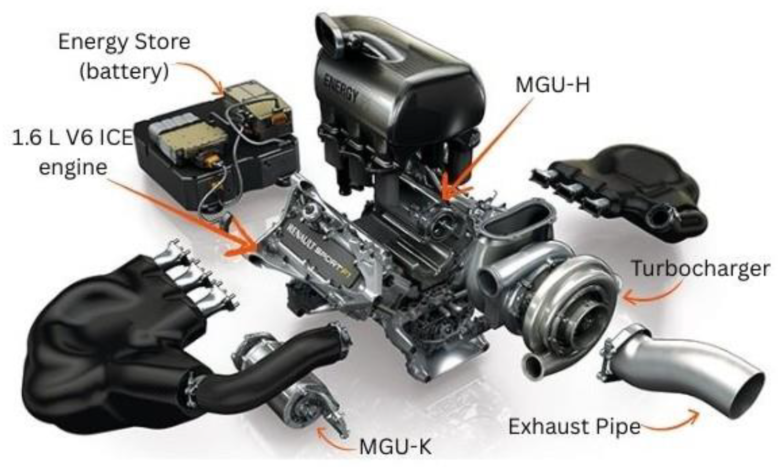
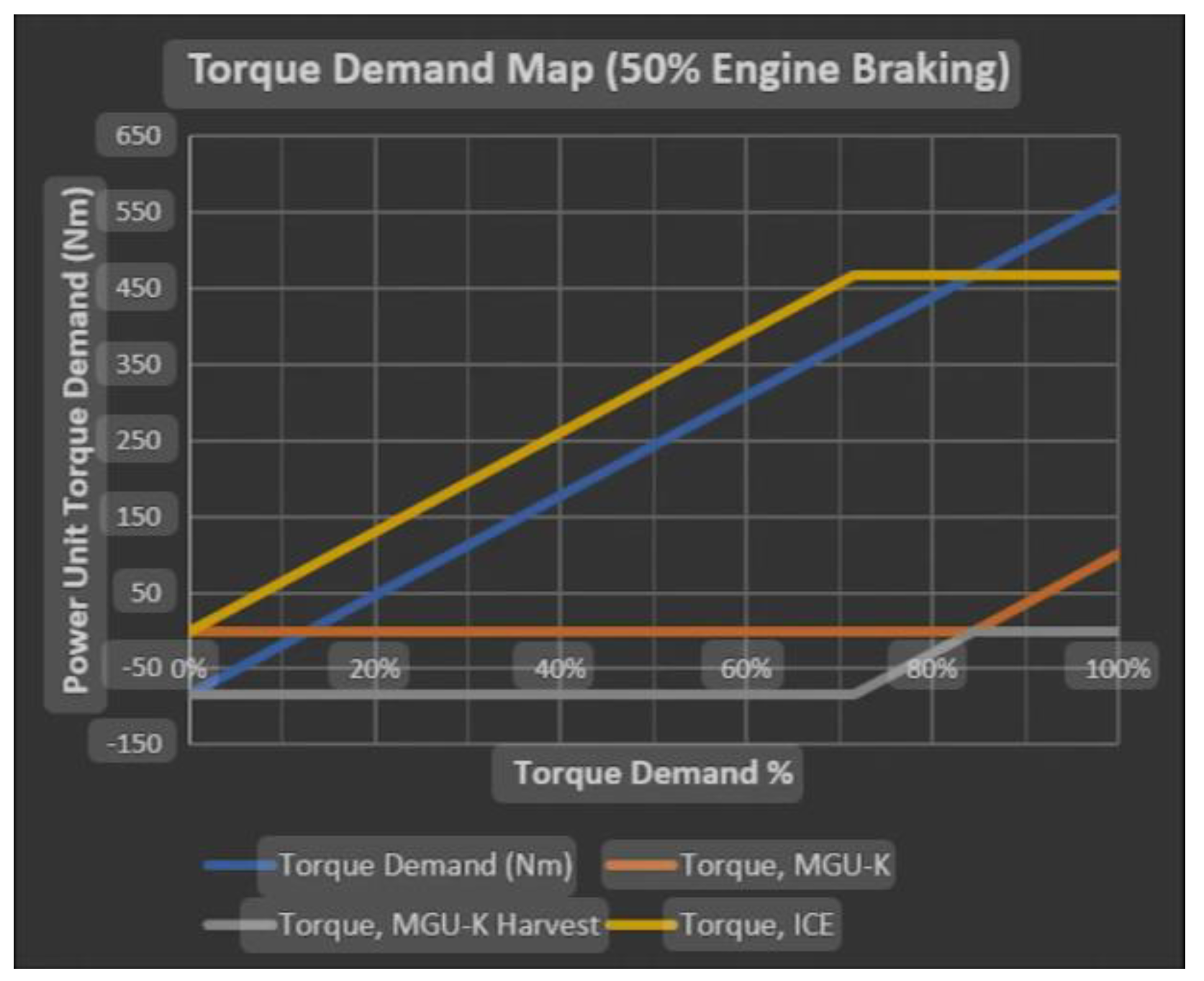
Figure 6.
Torque demand specification.
- 2)
- TC: The energy released by engine is used by Turbochargers (TC) to rotate its turbines and this rotational energy is passed to secondary turbine compressor (part of TC) which compresses the fresh air through F1’s air intake system and releases that compressed air into engine. At first, the compressed air is hot and is processed through intercooler and cool compressed air is transferred to engine. As the air is compressed, more air can fit inside engine resulting in more power generation and more performance. There is a situation when there is not enough heat energy produced by ICE for turbo to work especially at initial rpm. This lag where turbo is incapable of producing extra boost is called Turbo Lag. Although this equation is not common in literatures, it represents the dependence of turbo lag on Inertia of rotor, rotor speed and net torque.
Hence, the equation for turbo lag-
Where, τ lag= Turbo Lag
I rotor (in kg.m2) = Inertia of rotating components of Turbo Shaft (Compressor wheel, Turbine wheel, Shaft (transmits power from turbo to engine))
ω target (rad/s) = Angular velocity to produce targeted torque
τ exhaust (N. m) = torque applied by exhaust gas on turbo shaft at speed ω
τ load (N. m) = opposing torque applied by compressor, friction and air resistance at speed ω.
Derivation-
From Newton’s Second law of rotation-
(rotational analogue of F=ma)
Where, τ net= Net torque produced
I rotor= Inertia of rotating components of Turbo shaft.
α= Angular acceleration
Formula for Angular Acceleration
(Angular acceleration= change in angular velocity/ Time Required)
Substituting (2) in (1)-
where, τ net= τ exhaust- τ load
τ load= τ compressor + τ turbine + τ shaft
- 3)
- MGU-H: Motor generating unit- Heat (MGU-H) receives exhausts gas energy which the generator converts into electrical energy. This electrical energy is either directly provided for excess power generation via MGU-K so that it could further provide additional power to crankshaft or to TC compressor in order to prevent Turbo lag, or is directly stored in Energy Store (ES) i.e. Car battery for future use.
- 4)
- MGU-K: Motor generating unit-Kinetic (MGU-K) takes kinetic energy produced during braking of car which is then converted into electrical energy by the generator. This electrical energy is either stored in car battery or is provided to engine for excess power generation. It produces extra power of about 160 PS which adds up to 840 PS of engine core power. MGU-K stores about 2MJ of energy and loses about 4MJ of energy for a single lap.[3,4]
Let’s consider that an average Grand Prix has 55 laps-
So total energy stored- 2MJ x 55= 110MJ
And total energy discharged- 4MJ x 55= 220MJ
- 5)
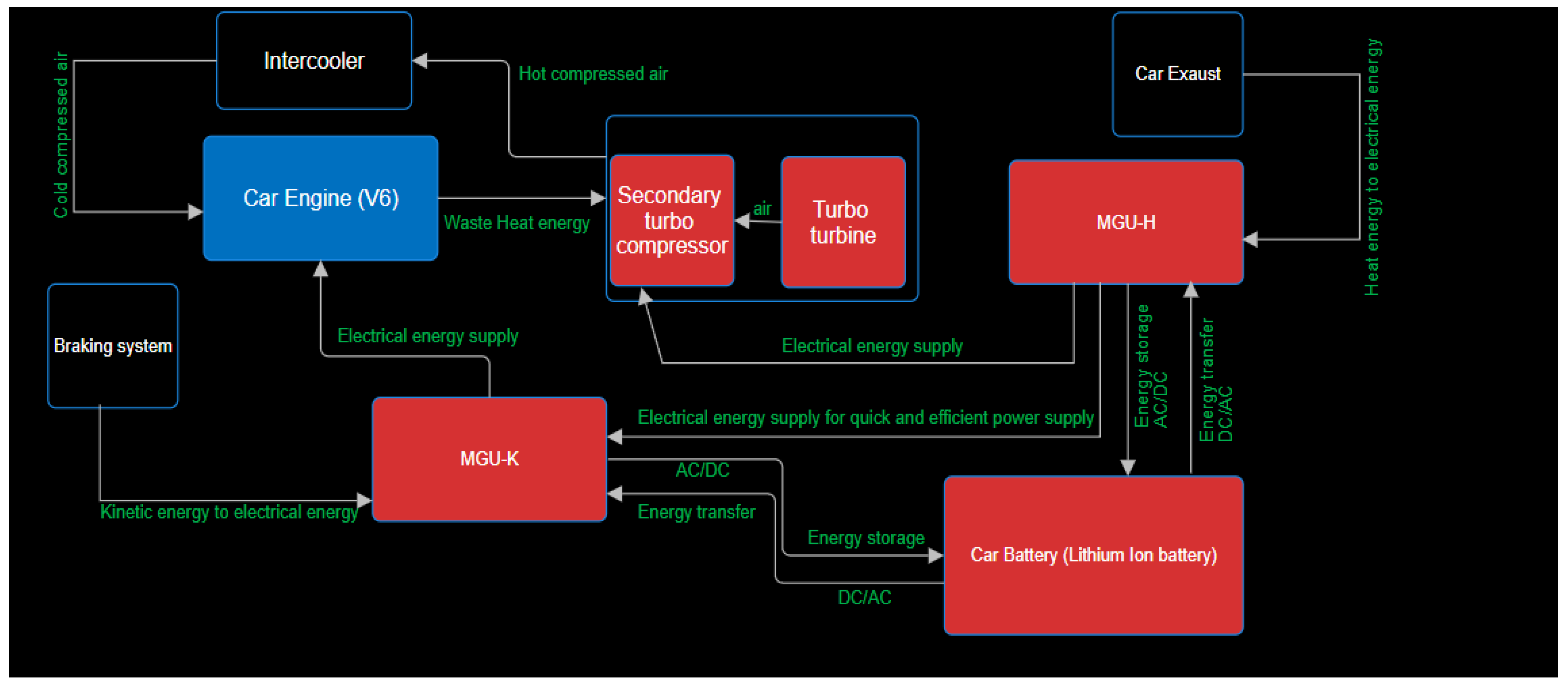
- Energy Store (ES): Lithium-ion battery is used in F1 cars as it provides a good power-to-weight ratio (stores large amount of power in a lightweight battery). Also, these batteries provide electrical energy whenever demanded by driver especially during cornering or overtaking with maximum efficiency (minimum loss of heat during energy transfer). Moreover, there AC/DC converters are attached when energy is transferred from MGU’s to battery as MGU’s operates on AC current whereas Battery operates on DC current. Similarly, DC/AC converters are attached for energy transfer from battery to MGU’s.
Figure 7.
Flowchart explaining power unit energy transfer.
Electronics and Control:
Figure 8.
Steering controls.
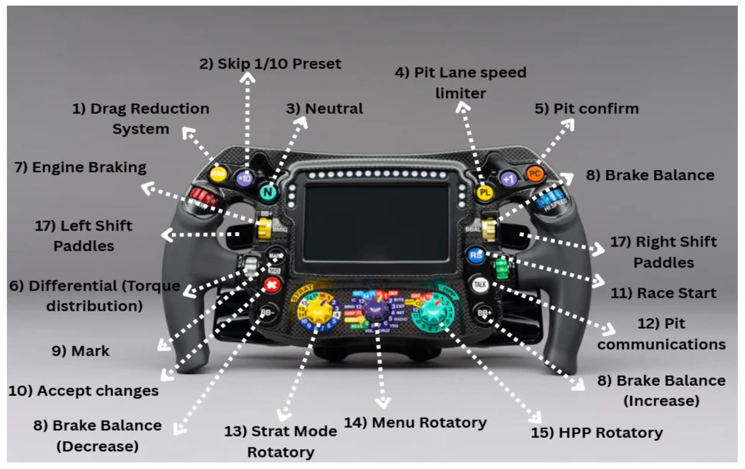
Formula 1 steering wheel does not only serve a purpose of steer, but also contributes in handling various configuration affecting car’s performance and aerodynamics during race. There are multiple controls on F1 steering wheel including around 3 rotatory knobs, radio button, differential, fuel hatch, engine start, LED, OLED display etc.[6]
Table 2.
Steering controls.
| Control/Button | Functionality |
|---|---|
| DRS button | Also known as Drag Reduction System button Helps in decreasing drag forces by opening rear wings for mor aerodynamics which helps in increasing car speed and overall performance |
| Skip 1/10 preset button | Allows drivers to perform rapid changes in car according to their track conditions such as modifying control systems such as Power Unit, engine mapping (engine responses to driver’s modifications). |
| Gearbox neutral | Allows the car gearbox to be in neutral configuration. |
| Pit lane speed limiter | Allows driver to set a speed limit when inside pit and this limiter is triggered through several track sensors and GPS when car is about to enter pit. So even if driver gives full throttle, the car would maintain its pit lane speed limit. |
| Pit confirm | Allows driver to send automated message to alert the crew team to get ready for pit box for some kind of upgrades like tire change or body part change. |
| Differential | Allows the driver to set a particular amount of torque to distribution between rear wheels especially during cornering or during apex. As F1 cars are Rear wheel drive (RWD), torque can only be transferred to rear wheels and not front wheels. |
| Engine braking | Feature allows driver to control the extent to which the car should slow down when not throttled or not applied brakes. |
| Brake balance | Allows driver to decide the brake force distribution between front and rear wheels. Generally, brake force distribution is done as 60/40 or 55/45 for more efficient and balanced braking as rear part of F1 car is heavy compared to front part. |
| Race start | This button signals engine for maximum power output. |
| Radio | Allows driver to communicate with engineers and crew members in the pit in order to discuss the implementation of race strategies or adjusting car configurations. |
| Strat mode rotatory | Allows driver to adjust engine stats such as ignition timing, fuel flow to get optimum performance during for crucial moments such as overtakes, cornering. |
| Menu rotatory | Allows driver to control the display of steering wheel such as its brightness, map or other information which is being displayed on screen. This does not affect car’s performance directly. |
| HPP rotatory | This is also known as High Performance Powertrain rotatory which adjusts certain power unit components such as MGU-K (control recovery of energy through barking system or providing of stored energy to engine) for excess power transfer whenever required during the race. |
| LED | LED shows the perfect time to upshift or downshift helping drivers to maintain the efficiency of the car. It also provides information whether energy is harvested or used. The LED colours may vary according to each driver’s preference in his car. |
| Shift Paddles | Left shift paddle is used for downshifts and right shift paddle is used for upshifts. |
Tyres:
Tires in F1 cars is a crucial part not only for traction but also for car performance during laps. The following picture shows different types of tyres used in F1 sprints and Grands prix. Different tyres have different usages based on their tyre designs and materials used known as compounds.[10]
Figure 9.
F1 Terrain Tyres.
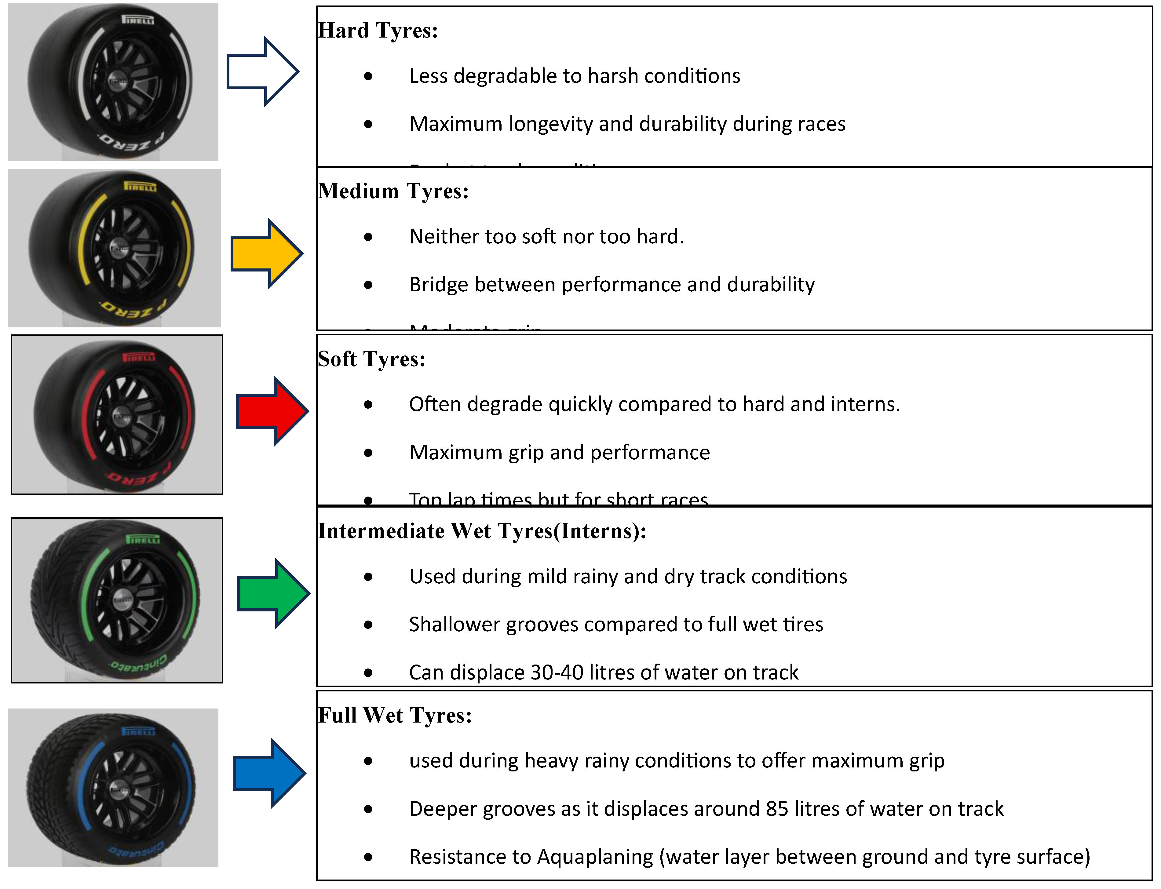
Table 3.
Types of Tyre Compounds.
| Compound | Characteristics | Hard | Medium | Soft |
|---|---|---|---|---|
| C1 | Hardest Compound | Y | N | N |
| C2 | Extreme Durability | Y | Y | N |
| C3 | Versatile Compound | Y | Y | Y |
| C4 | Superior Grip | Y | Y | Y |
| C5 | Soft compound | N | Y | Y |
| C6 | Maximum Softness | N | N | Y |
Pirelli, a leading manufacturer based in Milan, Italy supplies tyres to all F1 teams.
Table 4.
Tyres allocation based on track conditions.
| Events | Slick Tyres | Wet Tyres | Total Tyres allocated (Each Driver) | |||
|---|---|---|---|---|---|---|
| Hard Tyres | Medium Tyres | Soft Tyres | Wet Intermediate Tyres | Full Wet Tyres | ||
| Sprints | 2 | 4 | 6 | 5 | 2 | 19 |
| Grand Prix | 2 | 3 | 8 | 4 | 3 | 20 |
All these tyre changes are made according to different strategies made by teams based on weather and track conditions. Tyres are changed by team crew members during pit stops according to driver’s demand and team gameplan.
Transmission:
The F1 gearbox is mainly consists of clutch, layshaft, main shaft, selector barrels, selector forks, and gears. Components working is briefly explained below:
- 1)
- Layshaft and clutch: The power from engine is transferred from engine to layshaft which are small gears used to further rotate main gears (main shaft) when changed gears. This power from engine is transferred through a connection called input shaft which connects to clutch. The clutch further transfers power to layshaft.
- 2)
- Main shaft: The layshaft assists main shaft to rotate gears as if main shaft is provided direct power from engines, it would not be possible for gearbox to change gears when engine is active. Gears are mainly changed by gear paddles attached on F1 steering wheel. This paddles connection is attached to change cylinder which is further connected to selector barrel and this is connected to selector shaft.
- 3)
- Selector shaft: This component of F1 gearbox helps in changing and rotating specific gear (dog rings) according to driver’s demand. Specifically, selector shaft contains four selector forks which attaches to driver specific gear and rotates it accordingly. Further, selector shaft is attached to F1 differential system and this system connects to car wheels and provide engine power
- 4)
- Gear Teeth: The design of teeth i.e. a single component of a gear plays a crucial role in effective and smooth gear shifting without wear and tear. When two gears pass and roll over each other for transmitting power, it is called Meshing. The gear smoothness depends on the way meshing takes place. When the meshing point is near the lower bottom of other gear’s teeth, it transfers greatest stress and more vulnerable to gear teeth deformation.
Figure 10.
Gear Teeth Design - Normal Car (left) and F1 car (right).
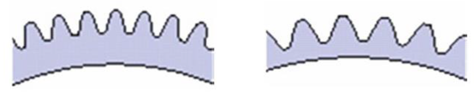
Figure 11.
Meshing process in normal cars (left) and F1 cars (right).
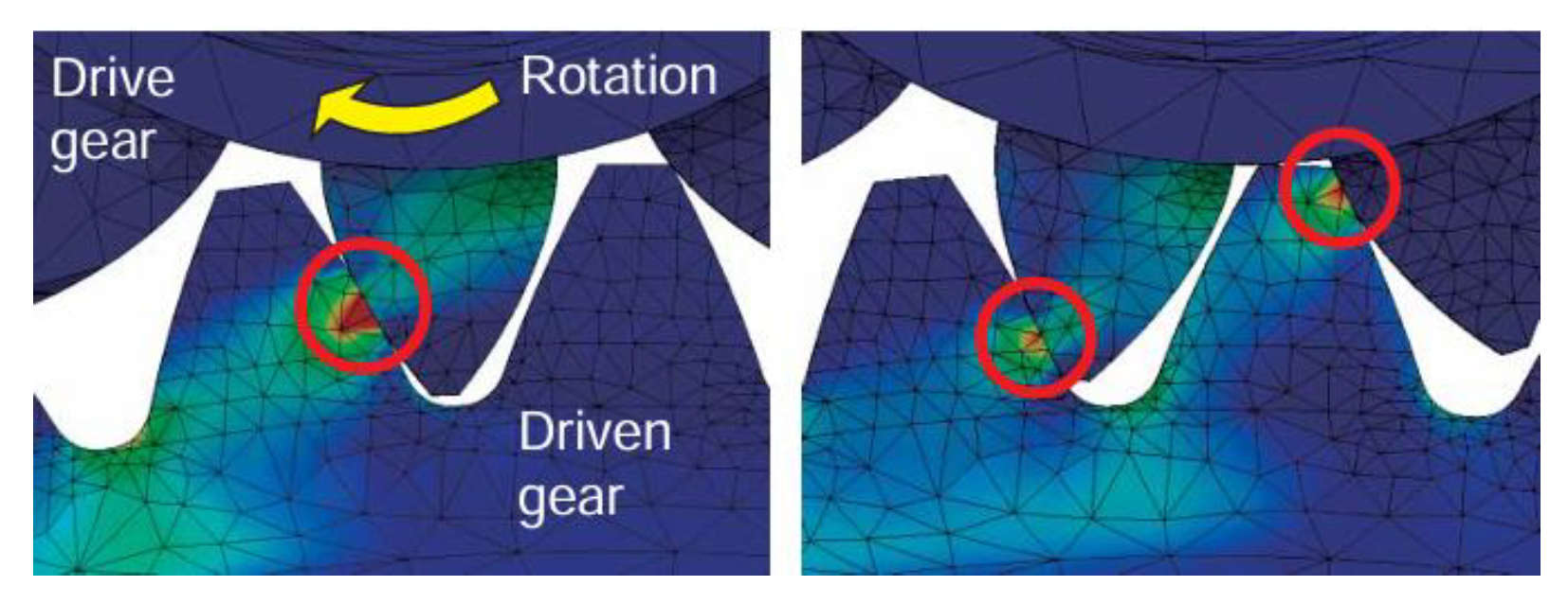
In normal cars gear meshing stresses pressure on one point, making it vulnerable to deformation. Whereas in F1 cars, meshing gears have two contact points and the stress developed in equally distributed between them. Hence reducing changes for deformation.
Factors leading to transmission fail:
Apart from gear deformation, other major factors leading to transmission fails in F1 cars-
- 1)
- Due to oil churning: Transmission failure due to oil churning takes place when excess lubricants such as grease which leads to sliding of certain components like gears which further leads to inefficiency in transmitting energy to differential system and then to wheels. This results in decreased car power and performance on track.
- 2)
- Due to torque transmission: Transmission failure due to torque transmission takes place due to increases friction between gear components, decreased energy transfer and torque due to oil intervention/leakage in gearbox.
- 3)
- Due to oil pump drive: Transmission failure due to oil pump drive takes place when there is loss of heat/ energy from input shaft which connects engine and transmission system. This causes reduced energy input from engine into gearbox and reduced power to wheels.
Overcoming transmission failure:
In order to overcome these failures, materials such as Diamond-Like Coating (DLC), carburizing techniques, lubrication oils were used. DLC provides strong, durable, deformative resistant material for car components reducing chances for deformation during high stresses on car systems. Carburizing involves carbon coating on a metal to harden the metal surface and prevent wear and tear. Lubrication oils provide a smooth and effective surface for car components to function and prevent friction, drag to a large extent.[8]
Sustainability and Future Trends of F1 Cars
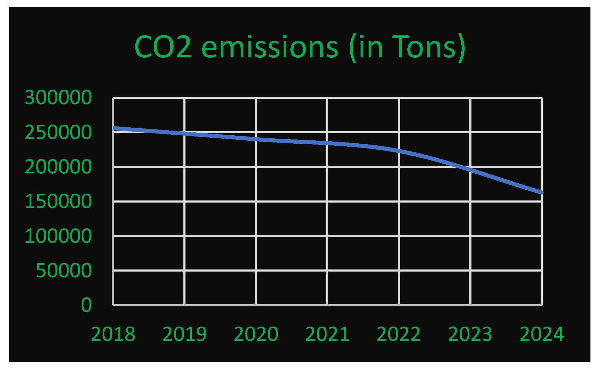
Modern F1 teams are actively participating in integrating car performance and environmental responsibility by modifying several car components. Due to F1 implementation of sustainable practices of reducing emissions, the greenhouse gases (GHG) from the car reduced by around 33000 tons from 2019-2022.
Figure 12.
Graph representing CO2 emission trend from 2018-2024.
In early stages of F1, they used powerful engines like V8, V10 and V12 to optimise car performance but unfortunately elevated harmful gas emissions as those engines were fully based on combustion without any waste recovery systems in that car. Gradually from 2009, they introduced Energy Recovery System (ERS) that includes MGU-K which recovers kinetic energy from wheels during braking and MGU-H which recovers heat energy from car exhaust (heat emissions) and convert it into electrical energy to improve performance. In this way, the KERS increases efficiency, on-ground emissions without affecting car performance. In fact, this system has triggered power input in the car. Moreover, the substances used as fuel also plays a vital role in determining the car efficiency.[5]
In the early stages of around 1950-1960s, fuel comprised of Benzene, Acetone, Methanol, Nitrobenzene mainly used to increase power output. A gradual shift took place in 1970s for using kerosene as fuel to increase efficiency and performance at the same time. After that, in 1980, high-octane gasoline (saturated hydrocarbon) was introduced for power and track performance as octane has good extent of compressing itself which generates more energy from engine. As there was rising awareness for sustainability and lowering CO2, NO2 emissions, biofuels such as Ethanol was introduced as it incorporates sustainability and performance to a great extent. F1 continues to implement various technologies to synchronize with rising environment safety regulations.[1]
Conclusions
Formula 1 is an intricate innovation which integrates high performance and prioritizes the evolution of safety factors and strength which is demanded with it. We have explored the working of crucial mechanics in F1. For strong and lightweight chassis, CFRP is used; magnesium alloys are used to dissipate heat and prevent over-heating; elements like titanium, aluminium alloys and steel alloys for mechanical components like pistons, gears and engine valves. F1 parts like Front/Rear wings, Venturi tunnels and Sliding Skirts play crucial role in maintain parallel and smooth flow of wind to minimise drag. This car is powered through V6 turbocharged supported by ES, exhaust system, MGU-K and MGU-H for extra torque boost. Car drivetrain modifications and radio communications are controlled through advanced steering wheel. F1 acquires six tyre types committed to varied dry and wet track conditions. Quick gear shifts take place through a sophisticated transmission system comprising of layshaft and main-shaft as supporting and driving gears and selector shafts for selecting gears. Gear teeth are uniquely designed for F1 cars to distribute gear-to-gear load uniformly and prevent gear wrecks. F1 has gained sustainability by innovating ERS and using biofuels such as Ethanol for environmental cleanliness. This study reveils the importance of cross-disciplinary fields in transcending the boundaries of performance and efficiency in modern engineering systems.
References
- Xenia Chiles; Formula 1’s Drive to Environmental Sustainability, SJTEIL, Volume 15, Issue2, (link).
- Xabier Castro, Zeeshan A. Rana; Aerodynamic and Structural Design of a 2022 Formula One Front Wing Assembly. [CrossRef]
- Jiashu Xu; Thermodynamic evaluation of 2026 Power Unit technical regulation changes in Formula 1. [CrossRef]
- Tomasz Kalociński, Lukasz Rymaniak, Pawel Fuc; Powertrain technology transfer between F1 and the automotive industry based on Mercedes-Benz. [CrossRef]
- moh Ime Ekanem, Aniekan Essienubong Ikpe; EVOLUTION OF FORMULA ONE (F1) MOTORSPORTS AND ITS TOP-NOTCH ADVANCEMENT IN ENGINEERING INNOVATIONS ACROSS THE RACING INDUSTRY, (ResearchGate).
- James Brown, Neville A Stanton, Kirsten M A Revell; The Evolution of Steering Wheel Design in Motorsport,. [CrossRef]
- Zhihao Zhang; Study on aerodynamic development in Formula One racing. [CrossRef]
- Koichi Konishi; Development of Honda Gears for Formula One Gearbox; [F1-SP2_17e].
- TOTALSIM: Secrets of Formula 1 Part 2 – Importance of Aerodynamics, June 14,2016 (link).
- Formula 1® tyre compounds; Pirelli Official website for tyres.
Disclaimer/Publisher’s Note: The statements, opinions and data contained in all publications are solely those of the individual author(s) and contributor(s) and not of MDPI and/or the editor(s). MDPI and/or the editor(s) disclaim responsibility for any injury to people or property resulting from any ideas, methods, instructions or products referred to in the content. |
© 2025 by the authors. Licensee MDPI, Basel, Switzerland. This article is an open access article distributed under the terms and conditions of the Creative Commons Attribution (CC BY) license (http://creativecommons.org/licenses/by/4.0/).
Copyright: This open access article is published under a Creative Commons CC BY 4.0 license, which permit the free download, distribution, and reuse, provided that the author and preprint are cited in any reuse.


