

Submitted:
08 August 2025
Posted:
12 August 2025
You are already at the latest version
Abstract
The Switched Reluctance Motor (SRM) is a strong candidate for high-performance industrial drives and electric vehicle (EV) propulsion due to its robust, magnet-free construction, high fault tolerance. The main drawback of the switched reluctance motor is the nonlinear behavior producing high torque ripple and noise these factors significantly hinder their widespread adoption. A novel alternative that is being investigated the last years to mitigate this problem is FCS-MPC (Finite Control Set Model Predictive Control), nevertheless the existing implementation use an eight-vector set as a base including single phase and dual phase excitation that don’t have equal magnitude, representing a nonuniform distribution in the αβ-plane. Therefore, this article, propose a novel eight vector set, that excites two phases in every vector with equal magnitude distributed in the αβ-plane, this new set of vectors result in smother current transitions, and reduce the torque ripple improve the dynamic behavior, this strategy is validated on the MATLAB/Simulink platform present detailed results comparing the proposed and the conventional method. The findings indicate a reduction in torque ripple by up to 58%, an improvement in acceleration time by up to 64%. The method demonstrates strong potential for scalable SRM performance enhancement in demanding applications such as EV drives.
Keywords:
switched reluctance motor
; model predictive control
; FCS MPC
; torque ripple
1. Introduction
The Switched Reluctance Motor (SRM) has emerged as a strong contender for industrial drives and electric vehicle (EV) applications due to its simple and robust construction, inherent fault-tolerant capability, and excellent performance at high speeds. Distinct from traditional machines, the Switched Reluctance Motor (SRM) eliminates the need for permanent magnets or rotor windings, thus presenting a cost-effective and magnet-free alternative. The SRM is a salient pole machine that use the magnetic reluctance minimization principle, the magnetic torque is generated with the alignment of the rotor with the stator magnetized poles. Due to this principle the motor lay on a nonlinear behavior that results in a significant torque ripple and acoustics noise which hinder broader adoption [1,2].
Recent investigations rely on Finite Control Set Model Predictive Control (FCS-MPC) as an advanced control strategy for SRMs, particularly for minimizing these issues. FCS-MPC possesses the capability to accommodate nonlinear dynamics and manage multiple control objectives concurrently. The majority of current research concentrates on the mitigation of torque ripple using a predetermined set of voltage vectors. Although several studies have suggested methods to vary or optimize this vector set, the fundamental set of eight switching vectors in an 8/6 SRM remains the standard framework for implementation [3].
This article proposes a novel set of switching vectors for FCS-MPC activating two active phases per vector while maintaining constant vector magnitudes. This approach differences from traditional strategies that incorporate combinations activating either a single phase or two phases with different magnitudes. The aim of this investigation is to conduct a comparative analysis between the proposed and conventional vector sets, focusing on analyzing performance metrics including torque ripple, torque-per-ampere ratio, dynamic response, energy efficiency, and speed tracking accuracy, which are critical for performance applications in electric vehicle propulsion systems. To provide a comprehensive performance benchmark, the proposed control is also evaluated versus a traditional PWM control scheme, commonly utilized in industrial SRM drives. This comparative test highlights the advantages of FCS-MPC in achieving multi-objective optimization, demonstrating its superior capacity to obtain speed tracking precision and torque ripple minimization. All simulations are executed via MATLAB/Simulink. The key contribution of this paper resides in the evaluation of conventional and propose method. This evaluation provides a more comprehensive understanding of SRM performance under different vector selection strategies.
The paper is organized as follows: Section II presents the mathematical model of the SRM. Section III describes the control strategy and details the implementation of the conventional and proposed vector sets. Section IV presents and discusses the simulation results. Finally, Section V concludes the study and outlines future research directions.
2. SRM Model
In this work it is used an 8/6 SRM, which means a four-phase machine with 8 poles in the stator and 6 rotor poles presented in Figure 1.
To generate the mathematical model of the 8/6 SRM, it is implemented in Simulink based on the following equation: [4]
where v is the voltage, R the internal resistance of the stator winding and ɸ the magnetic flux linkage. The block diagram is presented in Figure 2.
To obtain the mathematical model of a SRM, it is also important to consider the relationship between electrical angle and mechanical angle. For an 8/6 motor, the mechanical angle is calculated using the following equation:
θe represents the electrical angle, P represents the number of the rotor poles and θm corresponds the mechanical angle. Applying the analytical method proposed by [5], The characteristics of the motor under analysis are summarized in Table 1
To calculate the electromagnetic torque of the Switched Reluctance Motor (SRM), it is first necessary to determine the magnetic flux and subsequently the phase current. In this study, the analytical method proposed by Le-Huy is applied, using the following equations:
where correspond to magnetic flux saturated inductance maximum current.
where nonsaturated inductance.
The inductance profile as a function of rotor position is modeled by the shape function and its derivative with respect to the mechanical angle θ is given by.
where , is the number of rotor poles, mechanical angle position.
The flux linkage as a function of current i and rotor position θ is expressed as:
where is the unaligned inductance.
As shown in Figure 1, the magnetic flux and rotor position are used as inputs to a lookup table derived from magnetic characterization data. A curvilinear interpolation method, as described in [5], is employed to compute the current as a function of flux and position resulting in the interpolated current block (ITBL).
To compute the mechanical speed and position of the motor, the following dynamic equation is used:
where is the electrical torque, correspond to inertia, is the friction coefficient, correspond the angular speed, correspond the load torque.
3. Materials and Methods
3.1. FCS Model Predictive Control Conventional
Finite Control Set Model Predictive Control (FCS-MPC) is an advanced control strategy that relies on a predefined set of switching vectors to predict the future behavior of key system variables such as current, torque, flux, and rotor position. These predictions are evaluated using a cost function, which incorporates reference values for each variable. The relative importance of each term in the cost function can be tuned through weighting factors, allowing the control algorithm to prioritize specific performance objectives such as torque ripple reduction, current tracking accuracy, or flux regulation depending on the application requirements [6].
The operating principle of the Finite Control Set Model Predictive Control (FCS-MPC) is illustrated in Figure 3. The control loop begins by generating a speed error signal, which is the difference between the measured speed and the reference setpoint. This error is processed through a PI controller to generate the reference current.
Given the strong nonlinear behavior of the SRM, in which electrical variables are highly dependent on rotor position, two Look-Up Tables (LUTs) are implemented:
A Torque Look-Up Table (TLUT) to determine the torque reference from the current reference.
A Flux Look-Up Table (FLUT) to determine the flux reference under the same conditions.
These reference values are compared to the predicted torque and flux, which are computed by evaluating the future system states for each voltage vector in the predefined control set. A cost function is then calculated for each candidate vector, considering weighted error terms. The vector that minimizes the cost function is selected and applied to the converter in the next control cycle.
A set of eight switching vectors is defined for the Finite Control Set Model Predictive Control (FCS-MPC) strategy. The magnitude of each vector in the αβ plane is computed using the corresponding analytical expression (see Equation 10). The complete set of vectors is presented in Table II, which reflects a standard selection widely adopted in the literature. [7,8,9]
The asymmetric bridge converter, used to drive the Switched Reluctance Motor (SRM), operates in three distinct modes see Figure 4 . Taking phase A as an example, the switching sequence is as follows:
- Magnetization mode: Both switches S1 and S2 are turned ON, allowing current to flow through the phase A winding and building up magnetic flux(see Figure 4b).
- Freewheeling mode: Switch S1 is turned OFF while S2 remains ON. During this mode, the current circulates through S2 and the corresponding freewheeling diode, maintaining flux with no energy supplied from the source (see Figure 4c).
- Demagnetization mode: Both S1 and S2 are turned OFF, forcing the stored magnetic energy to dissipate through the demagnetization path. The current reverses direction due to the winding’s inductive nature, ensuring complete de-excitation of the phase (see Figure 4d).
For an 8/6 Switched Reluctance Motor (SRM) with four phases, the total number of switching combinations is 34=81, considering three states per phase (magnetization, freewheeling, and demagnetization). From this set, a subset of optimal vectors can be selected based on the following criteria:
- No more than two phases should be conducted simultaneously.
- Direct transitions from magnetization to demagnetization modes should be avoided.
The methodology used to predict the system’s behavior is based on the analytical model proposed by Le Huy. Starting from the fundamental voltage equation:
where the angular velocity is defined as:
By isolating the current derivative with respect to time, the expression becomes:
The partial derivatives of the magnetic flux with respect to rotor position and current are defined as follows:
To discretize the system, the forward Euler method is applied to Equation (13), yielding:
The mechanical angle prediction is performed using [10]
Once the predicted rotor position is available, it is substituted into the shape function derivative:
The predicted electromagnetic torque is then computed as.
The magnetic flux linkage is predicted using
The cost function formula is calculated using (21) where and are the weighting factors.
3.2. FCS Model Predictive Control Proposed
Previous studies have reported the existence of 81 possible switching vectors for the 8/6 Switched Reluctance Motor (SRM). However, considering the practical constraints and operating conditions of the converter, this number is typically reduced to 72 feasible vectors. From this reduced set, a conventional subset of 8 vectors as shown in Table II is commonly selected as the basis for control implementations. Nevertheless, limited attention has been given to exploring alternative vector combinations beyond this conventional subset.
In this work, we propose a novel vector selection strategy in which each switching vector consistently activates two phases, and all vectors are constrained to have the same magnitude. This criterion results in a new set of vectors presented in Table III.
As illustrated in Figure 5 (b), the proposed set leads to a circular trajectory of voltage vectors in the αβ plane, unlike the irregular distribution observed with the conventional vectors Figure 5 (a). This circular configuration contributes to smoother current transitions, which is beneficial because current dynamics are directly influenced by the applied voltage vectors and, in turn, strongly affect the generated torque. Maintaining uniform current transitions enhances control stability and can reduce torque ripple, one of the primary challenges in SRM operation.
The mathematical foundation to explaining the benefits of the proposed vector set is outlined as follows the conventional FCS-MPC implementation for a 4-phase SRM, the standard eight-vector set includes single-phase excitation vectors ∣V∣=2, and dual-phase excitation vectors with ∣V∣=2.828.
In the proposed method, all eight active vectors, excite exactly two phases simultaneously; and have equal magnitudes of ∣V∣=2.23 in the αβ plane.
They are uniformly spaced in angle adjusted to match the dual-phase excitation geometry. Consequently
let be the voltage vector in αβ coordinates using (Eq 10).
The conventional set satisfies , leading to an irregular octagon in αβ space. The proposed set maintains forming a perfect circle in αβ space. From the SRM current evolution (Eq 13), the magnitude of the applied voltage directly affects the slope . The conventional set alternates ∣V∣ between 2 and 2.828 resulting variable . and in non-uniform current rise and fall, notably when switching between single phase and dual phase vectors.
This causes torque ripple, since torque is proportional to current, as shown in Eq. 21.
Due to this factors the proposed control set the vector magnitude is constant, ensuring a uniform rate of current change. Two phases are always excited, allowing continuous torque contribution overlap between phases minimizing drops.
The circular αβ trajectory distributes energy evenly over the electrical cycle, enhancing torque symmetry and improving the SRM´s speed and transient response as indicated by the mechanical equation (Eq 9) resulting in smoother and more consistent torque profile and reducing oscillations. This enables faster acceleration less overshoot due to reduced excitation imbalance, and achieving a higher operational points under increased loads.
4. Results
The setpoint of the values for the simulations test are as follows rated al different speed values maintaining the torque under 0.1N*m the results are revealed in the Figure 6, Figure 7, Figure 8, Figure 9, Figure 10, Figure 11 and Figure 12.
To diferenciate the performance of the conventional and proposed method we used the following Ec. 22-24, where the peak to peak torque ripple , root-mean square (RMS) value of the phase current , average torque to ampere ratio γ, , , and Tmax are the average torque, minimum total instantaneous torque and maximum total instantaneous torque, and. t1 and t2 is the conduction time of phase current during a testing period.
As shown in Figure 6, both the proposed and conventional control methods reach a peak phase current of approximately 3 A. In the conventional approach, the current waveform exhibits pronounced ripple during the rising transient, with sharp variations in slope and amplitude. In contrast, the proposed method maintains a smoother current profile, with the transient ripple significantly reduced or almost entirely suppressed. This improvement indicates that the constant-magnitude dual-phase excitation contributes to a more uniform current evolution.
The conventional method exhibits a higher torque ripple compared to the proposed approach. In contrast, the torque response of the proposed method appears more uniform and exhibits reduced ripple as shown in Figure 7. This evaluation was conducted at 300 rpm and a load torque of 0.1 N·m.
The proposed method achieves the speed setpoint significantly faster than the conventional approach. Under the test condition of 300 rpm with a load torque of 0.1 N·m, the proposed method reaches the setpoint in 0.41 seconds, whereas the conventional method requires 1.19 seconds to achieve the same target as illustrated in Figure 8.
As illustrated in Figure 9, the proposed method achieves a significantly higher torque-per-ampere ratio compared to the conventional approach. Specifically, it reaches 0.22 N·m/A, whereas the conventional method achieves only 0.16 N·m/A, under the same initial condition of 300 rpm and a load torque of 0.1 N·m.
Both the proposed and conventional methods exhibit a peak current of 3.2 A. However, the conventional method keeps displaying a noticeable increase in current ripple during the initial transient, a phenomenon that is significantly attenuated or absent in the proposed method as observed in Figure 10.
At 600 rpm, the conventional controller produces larger torque ripple, while the proposed method maintains a more stable torque output with reduced fluctuations see Figure 11.
The proposed method reaches the reference speed in 0.9 s, significantly faster than the 2.52 s required by the conventional controller, highlighting the advantage in dynamic response, as shown in Figure 12.
Consistent with low-speed results, the proposed method sustains a higher torque-per-ampere ratio compared to the conventional strategy as illustrated in Figure 13.
As shown in Figure 14, both the proposed and conventional methods reach a peak current of 4 A. While at lower speeds the proposed method consistently exhibits smoother current waveforms and the conventional approach displays pronounced ripple, this trend changes at higher speeds. In this operating condition, the conventional current waveform appears smoother, whereas the proposed method presents localized peaks. This behavior is attributed to the SRM operating near its maximum capability in the proposed scheme, where the current approaches magnetic saturation. Nevertheless, despite the apparent smoothing in the conventional current profile at this speed, torque ripple analysis confirms that the proposed method continues to achieve lower torque ripple, thereby maintaining superior torque quality.
As shown in Figure 15, the proposed method achieves the speed setpoint significantly faster than the conventional approach. Under the test condition of 1200 rpm with a load torque of 0.1 N·m, the proposed method reaches the setpoint in 2.2 seconds, whereas the conventional method requires 9 seconds to achieve the same target.
Figure 16 displays a higher torque ripple in the conventional method compared to the proposed approach. In contrast, the torque response of the proposed method appears more uniform and exhibits reduced ripple. This evaluation was conducted at 1200 rpm and a load torque of 0.1 N·m.
Figure 17 presents the torque-per-ampere ratio remains consistent with the values observed at lower speeds. The proposed method maintains a higher ratio, while the conventional method continues to exhibit a lower value under the same operating conditions.
Figure 18 depicts the torque setpoint tracking as the load increases. Under these conditions, the conventional method fails to maintain the load at the reference speed, whereas the proposed method sustains it without difficulty. As observed in Figure 19, when the load reaches 0.3 N·m, the conventional method exhibits a noticeable speed droop, while the proposed method maintains smooth and stable speed tracking.

Table 4.
PWM and DTC Comparative Resuls.
| FCS-MPC | T Ripple (%) |
Acceleration time (s) |
Efficiency (%) |
Voltage (%) |
Current (%) |
|---|---|---|---|---|---|
|
CONVENTIONAL TL=0.1Nm nref=300rpm |
277% | 1.19 | 81% | 8 | 0.94 |
|
PROPOSED TL =0.1Nm nref=300rpm |
115% | 0.41 | 87% | 16 | 0.90 |
|
CONVENTIONAL TL=0.1Nm nref=600rpm |
207% | 2.52 | 81.5% | 7 | 1.25 |
|
PROPOSED TL =0.1Nm nref=600rpm |
129% | 0.9 | 85.7% | 11 | 1.2 |
|
CONVENTIONAL TL=0.1Nm nref=1200rpm |
165% | 9 | 80% | 3.2 | 0.86 |
|
PROPOSED TL =0.1Nm nref=1200rpm |
148% | 2.2 | 82.5% | 4.2 | 0.8 |
Although the proposed method increases voltage THD by 40–60% compared to the conventional FCS-MPC, the current THD decreases by 4–8%. This is because the uniform voltage magnitude and balanced excitation angles distribute energy more evenly over the electrical cycle, reducing harmonic torque components and smoothing current waveforms. In EV applications, the reduced current THD translates to lower copper losses, less winding heating, and extended component lifespan benefits that outweigh the moderate increase in voltage distortion.
To further validate the proposed control strategy, a performance comparison was conducted against a conventional PWM-based control scheme at 600 rpm and a load torque of 0.1 N·m. The PWM controller was configured with a 2 kHz switching frequency, a turn-on angle of 42°, and a turn-off angle of 57°. The speed control loop employed a PI regulator, and a separate PI controller was implemented for current regulation (see Figure 20). Simulation results (Figure 21 and Figure 22) indicate that, although the PWM controller exhibits a faster dynamic response than both the conventional and proposed FCS-MPC methods, it suffers from significantly higher steady-state speed tracking error. Moreover, the PWM scheme produces a torque ripple of approximately 272% as shown in Figure 23, far exceeding the levels achieved with either FCS-MPC implementation. These findings highlight the ability of FCS-MPC particularly with the proposed constant-magnitude dual-phase vector set to manage multiple performance objectives simultaneously, delivering both improved speed tracking and substantial torque ripple reduction.
and Figure 25 present the α–β flux trajectories for the conventional and proposed control strategies, respectively. In the conventional method (Figure 24), the trajectory exhibits an irregular, asymmetric shape with non-uniform segment lengths, indicative of variable voltage vector magnitudes and inconsistent excitation between single- and dual-phase states. This irregularity can contribute to non-uniform current slopes and, consequently, higher torque ripple.
Figure 24.
Results of flux trajectory flux alpha vs beta with Conventional control.
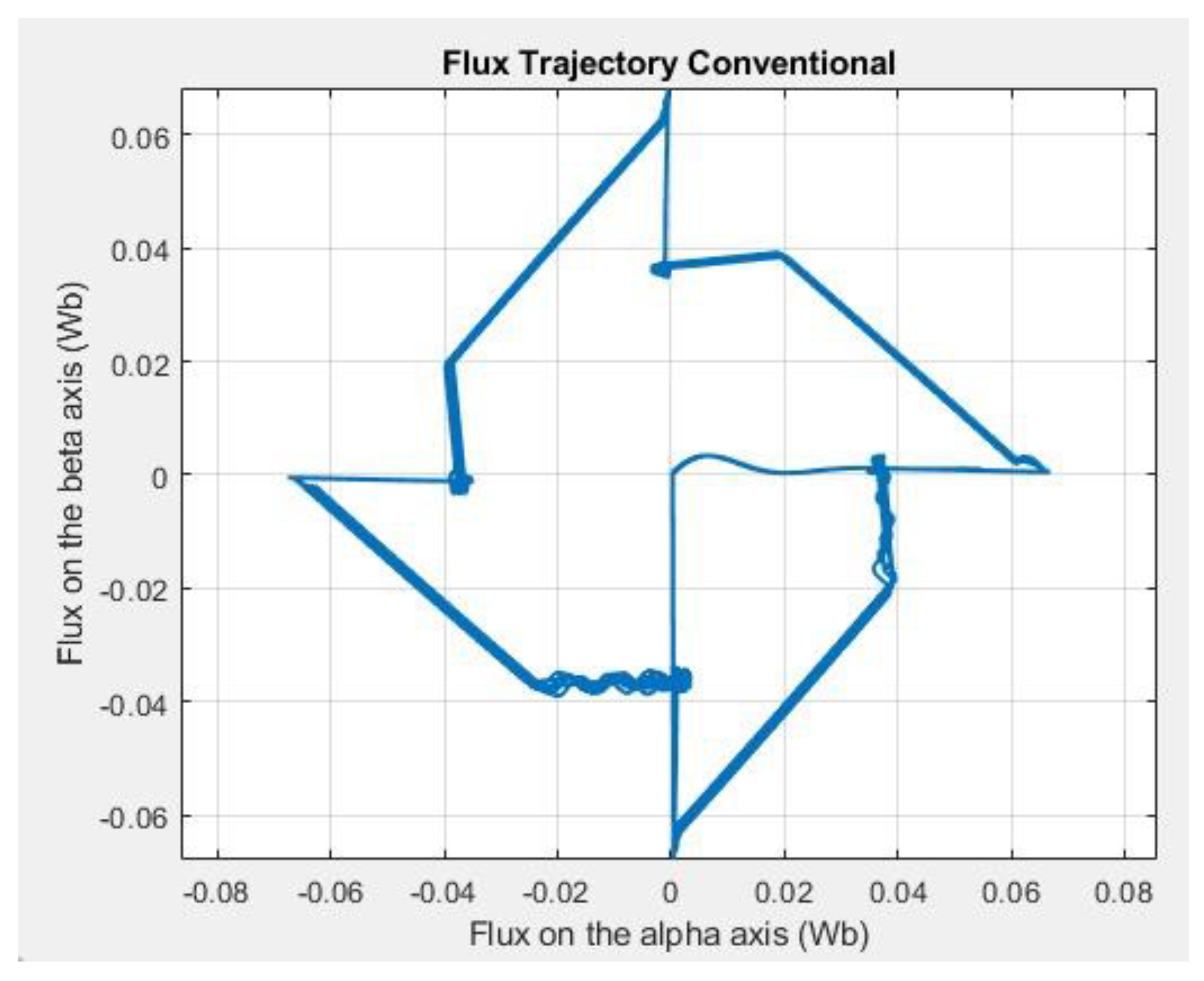
Figure 25.
Results of flux trajectory flux alpha vs beta with Proposed control.
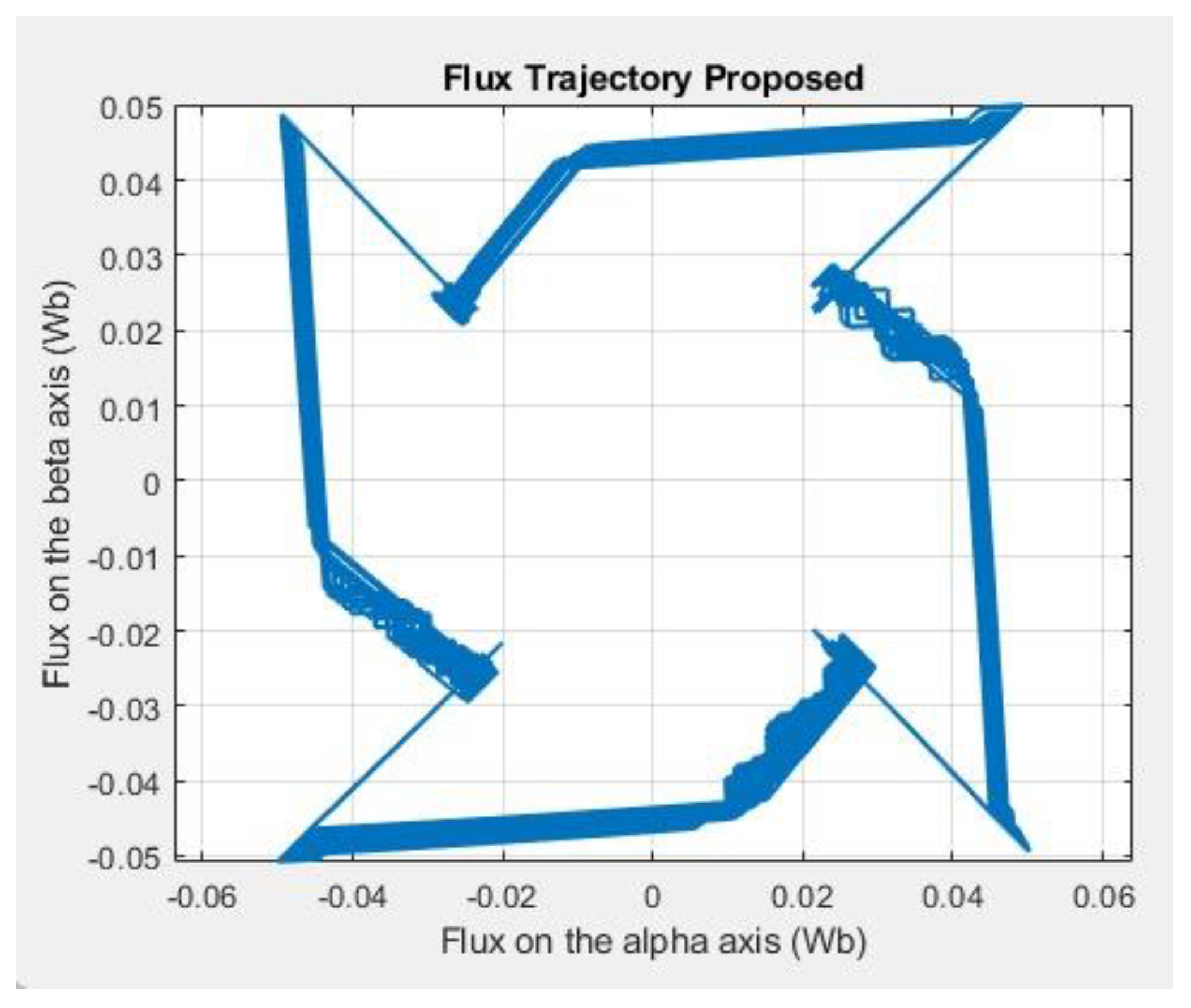
In contrast, the proposed method (Figure 25) produces a trajectory that is more uniform and closely aligned with a circular path, reflecting the constant-magnitude voltage vector distribution in the αβ plane. This regular pattern implies more balanced excitation across all sectors, leading to smoother current transitions, improved torque symmetry, and reduced torque ripple. The improved geometric uniformity of the flux trajectory directly correlates with the enhanced dynamic performance observed in the proposed control scheme.
To assess the computational efficiency of the proposed FCS-MPC method in comparison to the conventional approach, simulations were profiled using the built-in Simulink Profiler. The models were executed under identical conditions: a fixed step size of 10 µs and a total simulation duration of 4 seconds, resulting in 400,000 discrete steps.
The profiling results are summarized in Table V. The run time required for the conventional controller was 415.36 seconds, while the proposed method completed the same simulation in 109.75 seconds. This indicates a computational time reduction of approximately 73.6%.
Moreover, the run-to-simulation time ratio (CPU time required per simulated second) was 103.84 for the conventional controller, compared to only 27.44 for the proposed strategy. This metric further demonstrates that the proposed method is significantly more efficient and better suited for real-time implementation, especially in embedded control systems where processing resources are limited.
Although the present study focuses on an 8/6 SRM topology, the qualitative insights obtained can be extended to other configurations, including 6/4, 12/8, and nonconventional geometries. Nevertheless, the interplay between the rotor–stator pole ratio, the inductance profile, and the torque generation mechanism is a determining factor in the relative effectiveness of each control strategy.
5. Conclusions
This work has presented a finite-control-set model predictive control (FCS-MPC) strategy for an 8/6 switched reluctance motor (SRM), introducing a constant-magnitude voltage vector set that consistently excites two phases simultaneously. Unlike the conventional approach, which combines single- and dual-phase excitation vectors of non-uniform magnitudes, the proposed method generates a circular, evenly spaced trajectory in the αβ plane, ensuring smoother current transitions and more symmetric torque profiles.
MATLAB/Simulink simulations, conducted under identical operating conditions, lead to the following key conclusions:
The proposed method achieves up to 58% torque ripple reduction compared to the conventional controller, maintaining this improvement across a wide speed range, including near magnetic saturation.
Acceleration time is reduced by up to 64%, demonstrating a faster reaction to reference and load changes.
At low and medium speeds, the proposed controller delivers a substantially smoother current profile, minimizing the transient oscillations present in the conventional approach.
Superior torque current ratio across all tested conditions, the proposed method achieves a higher torque-per-ampere ratio, indicating more efficient use of available current.
Impact on harmonic distortion while the proposed strategy moderately increases voltage THD, it reduces current THD, suggesting a more favorable electromagnetic behavior of the machine.
Robustness under load variations in load-increase scenarios, the proposed method maintains the reference speed without significant droop, whereas the conventional approach experiences notable speed degradation.
Overall, the findings confirm that constant-magnitude dual-phase excitation not only enhances torque quality and current stability but also provides notable dynamic advantages, making it a strong candidate for high-demand applications such as electric vehicle propulsion. However, the moderate increase in power losses and voltage THD should be considered in designs aiming for maximum efficiency.
Future work will include experimental validation on physical prototypes, adaptive optimization of the vector angular spacing, and the exploration of applicability to nonconventional SRM topologies and high continuous-load operation.
Author Contributions
Conceptualization, writing—original draft preparation, Franklin Sánchez. And Maribel Milanés.; methodology, Enrique Romero; investigation, Gabriel Moreano; writing—review and editing, Jacqueline Llanos.
Acknowledgments
This section will be completed after the article acceptance.
Conflicts of Interest
The authors declare no conflicts of interest.
References
- D. Mohanraj, J. Gopalakrishnan, B. Chokkalingam, and L. Mihet-Popa, “Critical Aspects of Electric Motor Drive Controllers and Mitigation of Torque Ripple - Review,” 2022, Institute of Electrical and Electronics Engineers Inc. [CrossRef]
- L. Ge et al., “Model Predictive Control of Switched Reluctance Machines with Online Torque Sharing Function Based on Optimal Flux-Linkage Curve,” IEEE Transactions on Transportation Electrification, vol. 10, no. 3, pp. 4990–5001, 2024. [CrossRef]
- D. F. Valencia, R. Tarvirdilu-Asl, C. Garcia, J. Rodriguez, and A. Emadi, “A Review of Predictive Control Techniques for Switched Reluctance Machine Drives. Part II: Torque Control, Assessment and Challenges,” IEEE TRANSACTIONS ON ENERGY CONVERSION, vol. 36, no. 2, p. 1323, 2021. [CrossRef]
- F. Sánchez, M. Milanés, E. Romero, E. González, C. Roncero, and F. Barrero, “A Simulation Based Comparison of Pwm and Dtc Control for 8/6 Srm,” in 2025 19th Conference on Electrical Machines, Drives and Power Systems (ELMA), IEEE, Jun. 2025, pp. 1–6. [CrossRef]
- H. Le-Huy and P. Brunelle, “A versatile nonlinear switched reluctance motor model in simulink using realistic and analytical magnetization characteristics,” in IECON Proceedings (Industrial Electronics Conference), 2005, pp. 1556–1561. [CrossRef]
- Jose. Rodriguez, Wiley - IEEE : Predictive Control of Power Converters and Electrical Drives (1). Wiley-IEEE Press, 2012.
- M. Deepak, G. Janaki, and C. Bharatiraja, “Performance Evaluation of Direct Torque Control and Model Predictive Control Based on Voltage Vector Strategy for SRM Drive,” in 2024 3rd International Conference on Power, Control and Computing Technologies, ICPC2T 2024, Institute of Electrical and Electronics Engineers Inc., 2024, pp. 363–368. [CrossRef]
- A. Xu, C. Shang, J. Chen, J. Zhu, and L. Han, “A New Control Method Based on DTC and MPC to Reduce Torque Ripple in SRM,” IEEE Access, vol. 7, pp. 68584–68593, 2019. [CrossRef]
- W. Ding, J. Li, and J. Yuan, “An Improved Model Predictive Torque Control for Switched Reluctance Motors With Candidate Voltage Vectors Optimization,” IEEE Transactions on Industrial Electronics, vol. 70, no. 5, pp. 4595–4607, May 2023. [CrossRef]
- D. Lv, W. Ding, Y. Wang, K. Wang, S. Chen, and J. Cai, “Finite Control Set Model Predictive Torque Control of Switched Reluctance Motor Based on Three-Phase Four-Leg Inverter,” IEEE Transactions on Industrial Electronics, 2025. [CrossRef]
Figure 1.
Basic configuration of the 8/6 SRM.

Figure 2.
SRM block diagram.
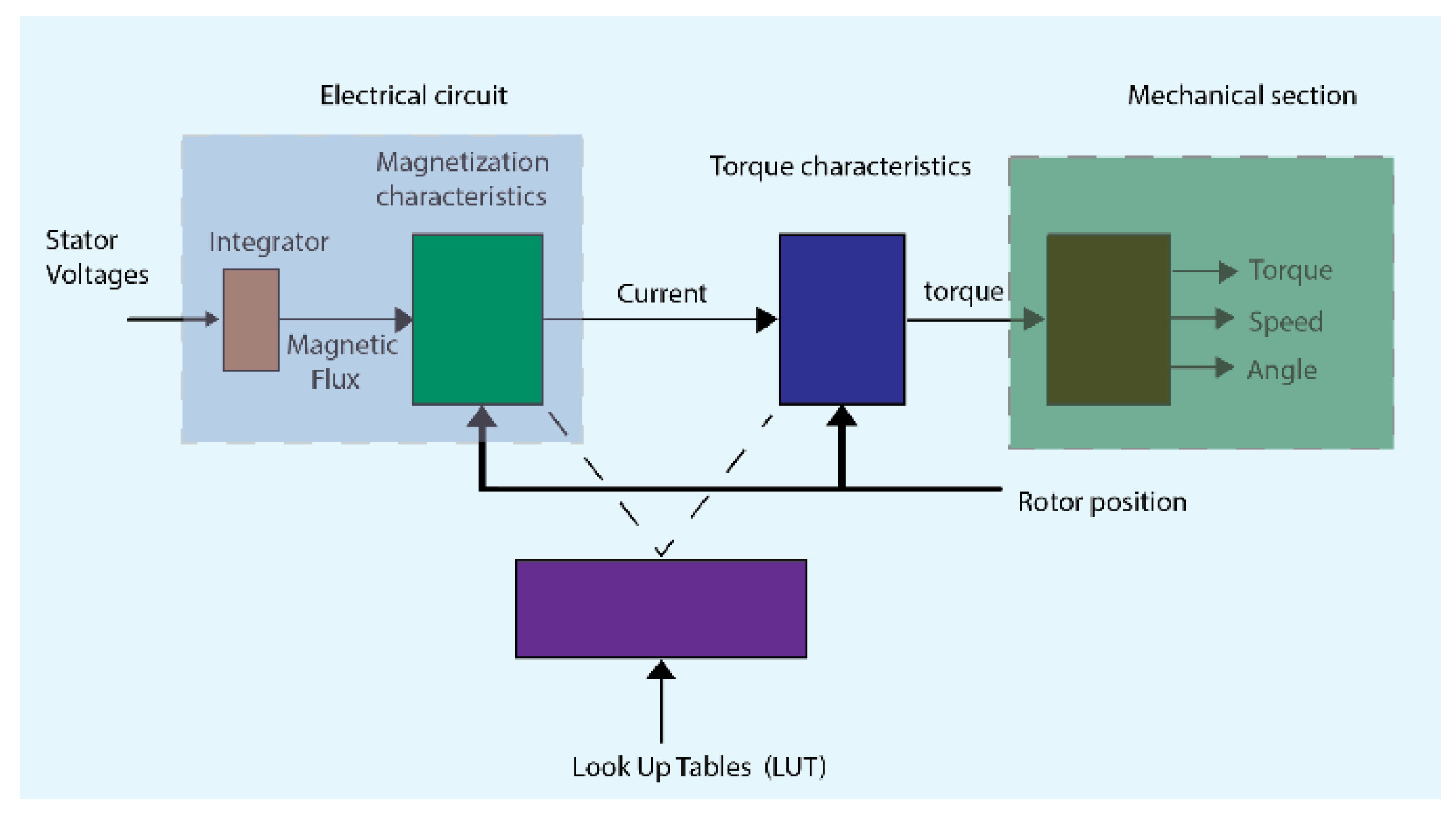
Figure 3.
FCS-MPC system block.
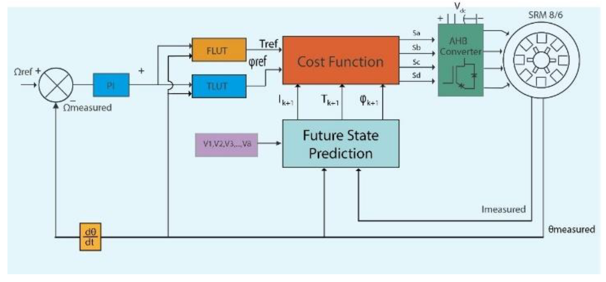
Figure 4.
Asymmetric bridge converter modes of operation.
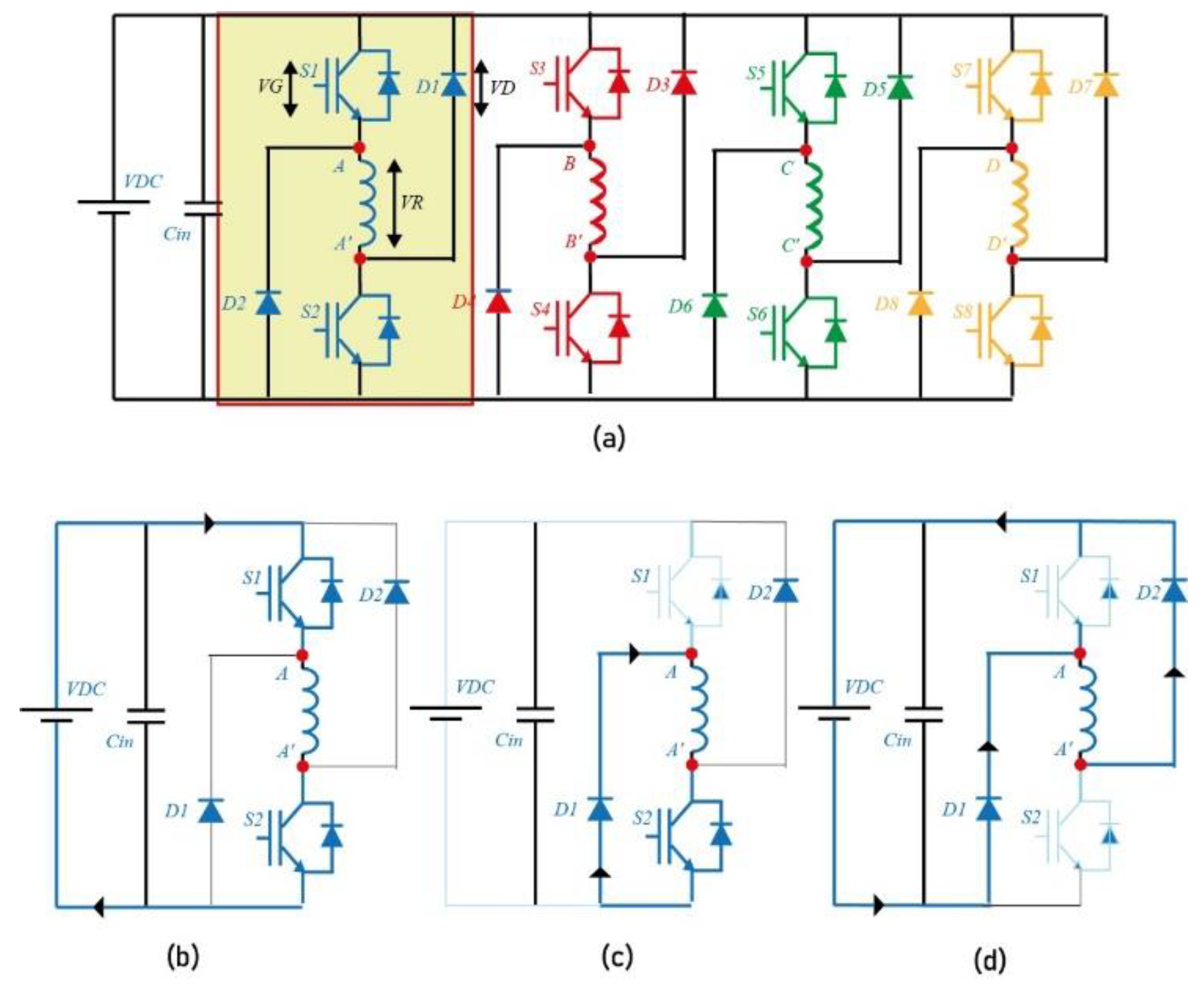
Figure 5.
Set of vectors distributed on αβ plane .
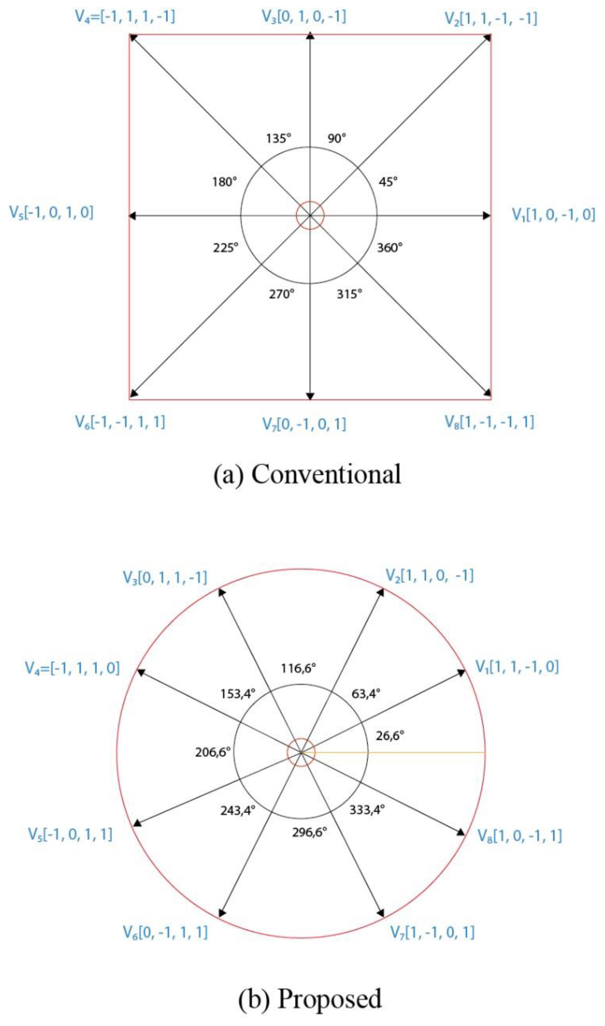
Figure 6.
Simulation results of current phase A w=300 rpm Tl=0.1N*m.
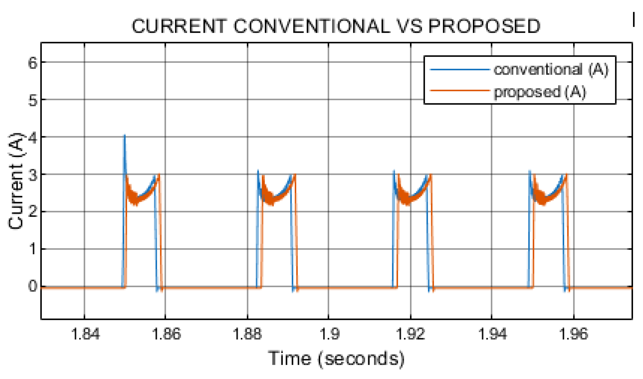
Figure 7.
Simulation results of torque w=300 rpm Tl=0.1N*m.
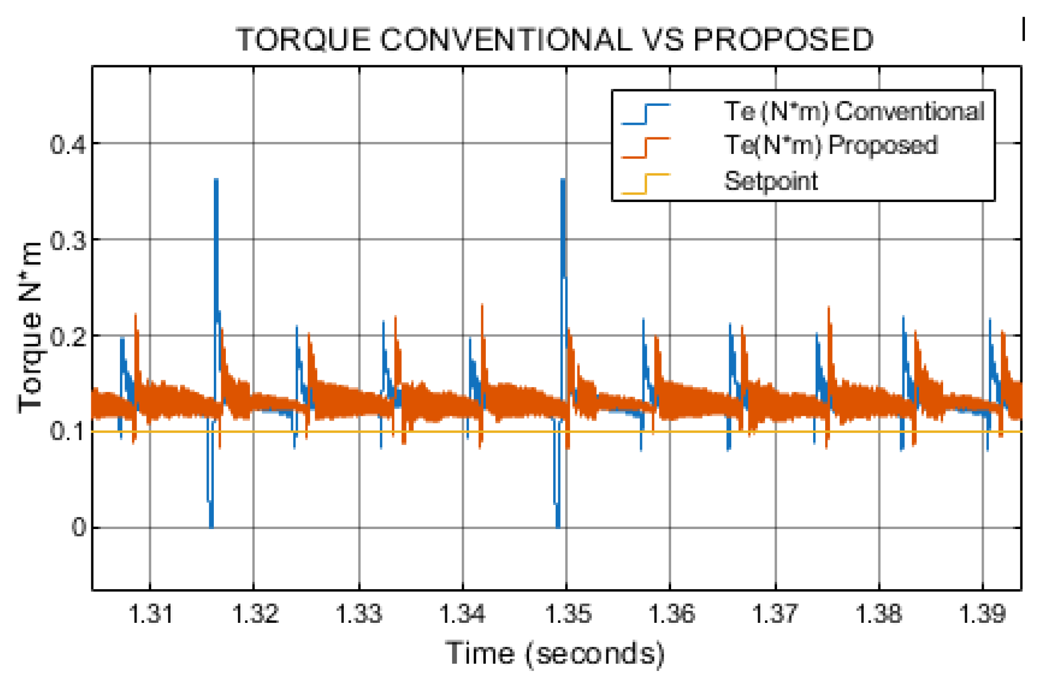
Figure 8.
Simulation results of speed w=300 rpm Tl=0.1N*m.
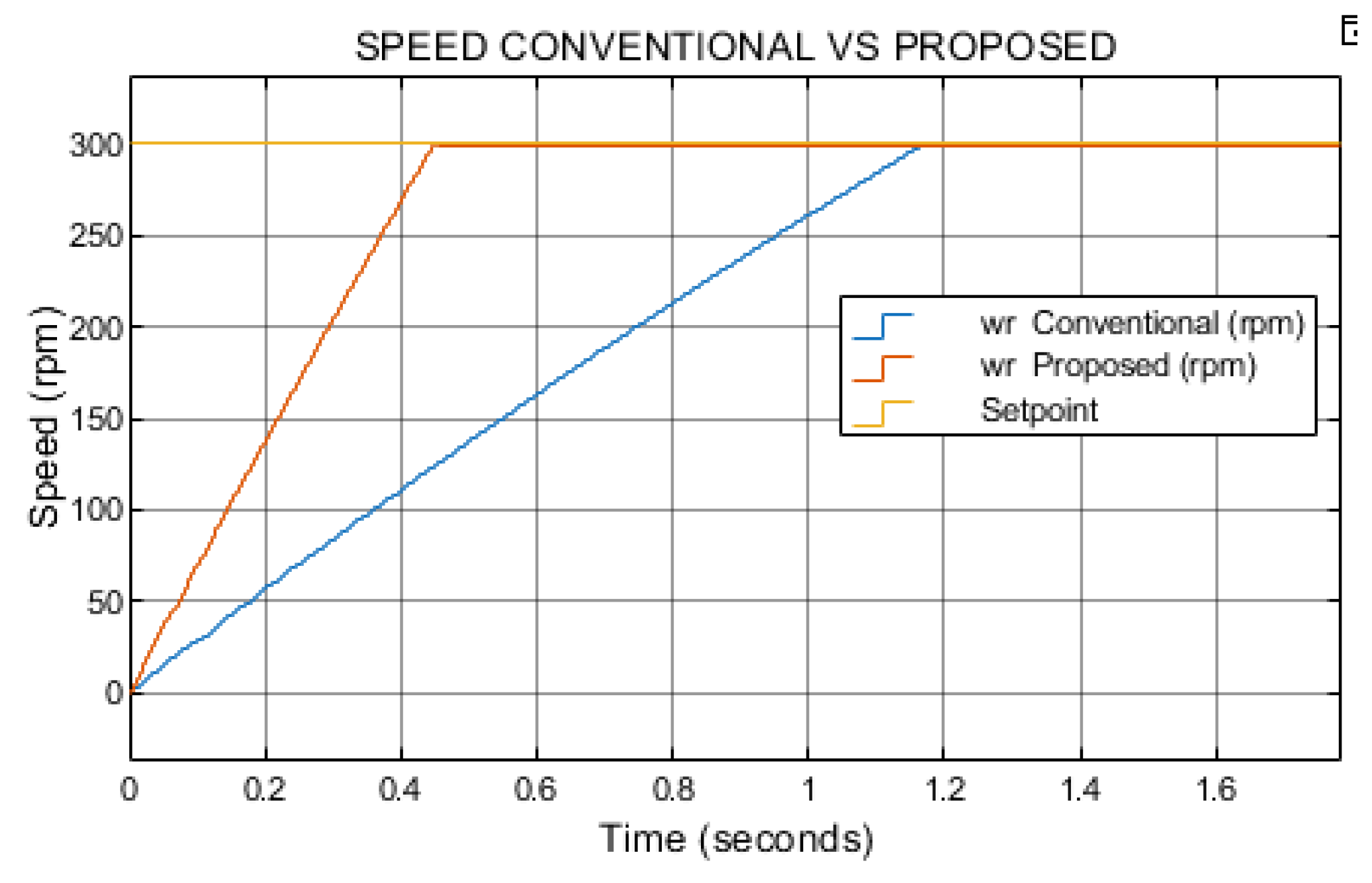
Figure 9.
Results of Te/A ratio Conventional Vs Proposed, w=300 rpm Tl=0.1N*m.
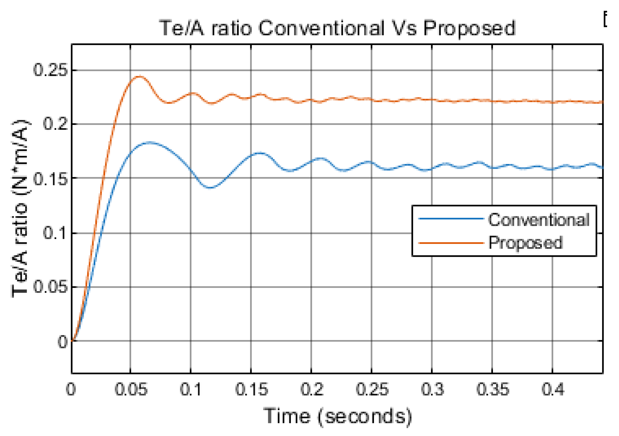
Figure 10.
Simulation results of current phase A w=600 rpm Tl=0.1N*m.
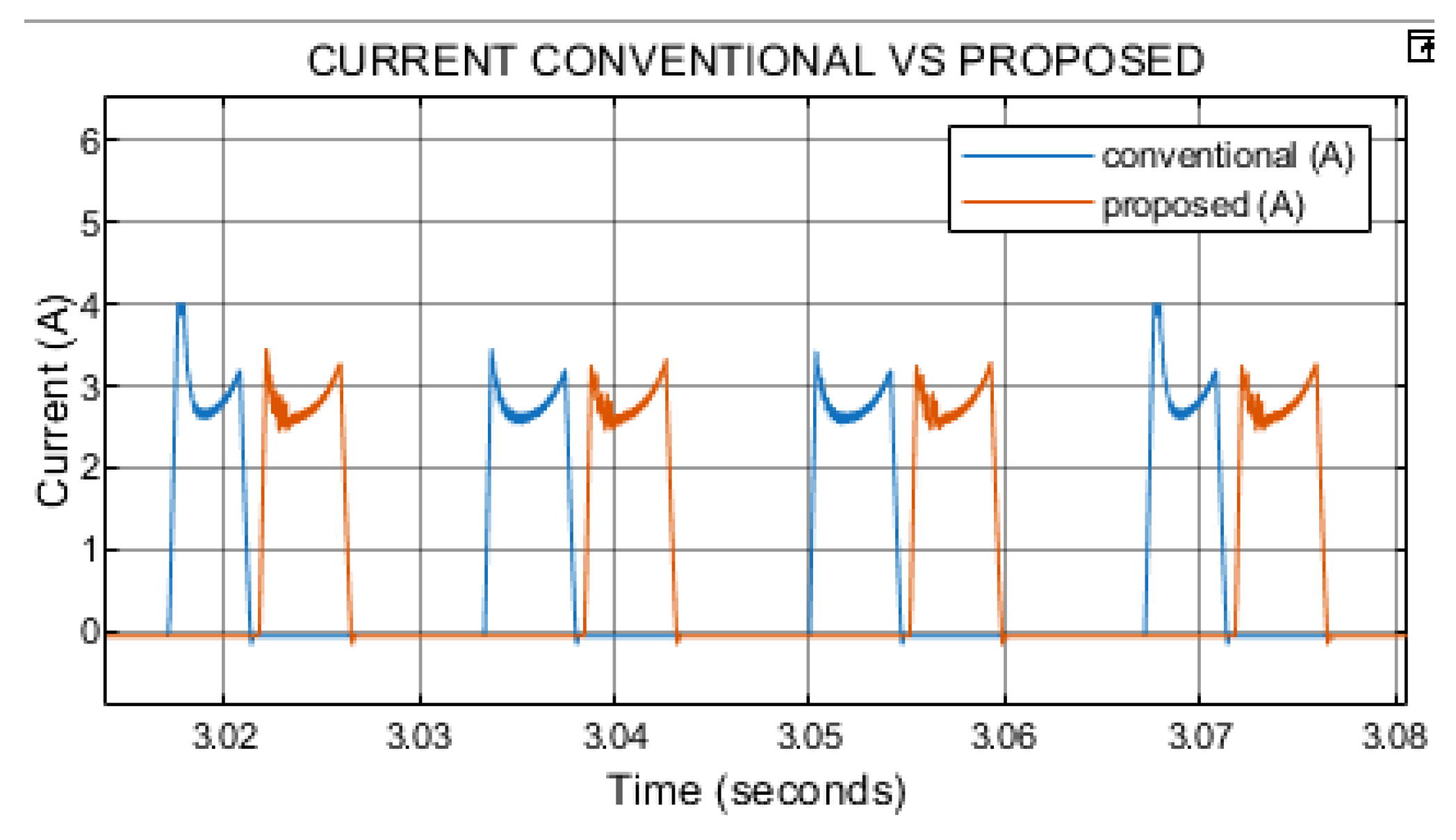
Figure 11.
Simulation results of torque w=600 rpm Tl=0.1N*m.
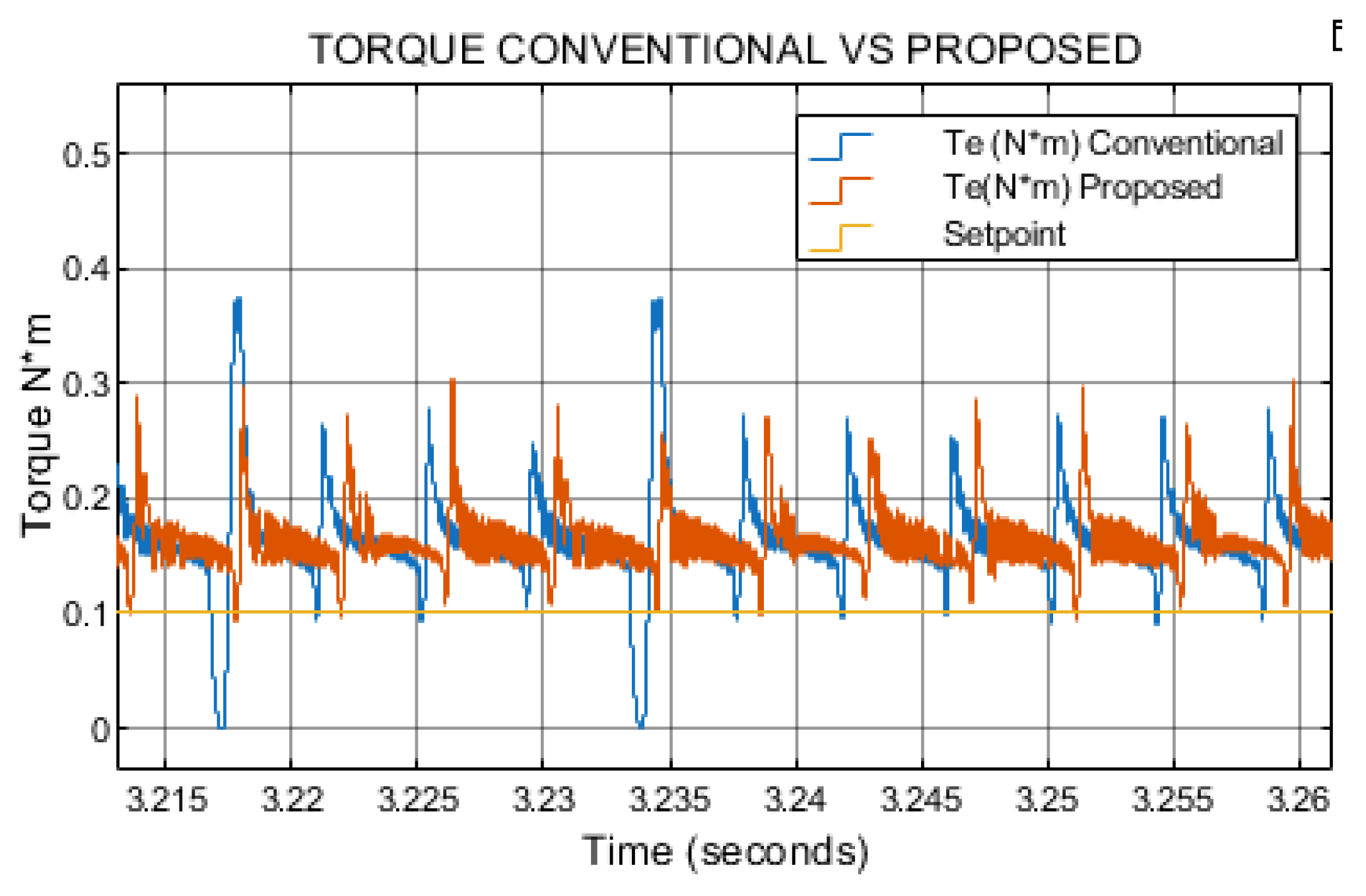
Figure 12.
Simulation results of speed w=600 rpm Tl=0.1N*m.
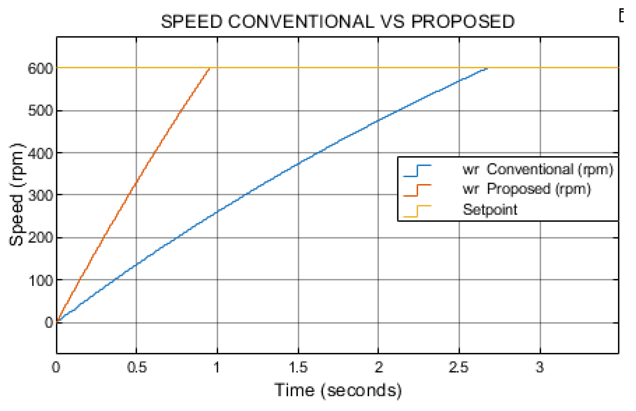
Figure 13.
Results of Te/A ratio Conventional Vs Proposed, w=600 rpm Tl=0.1N*m.
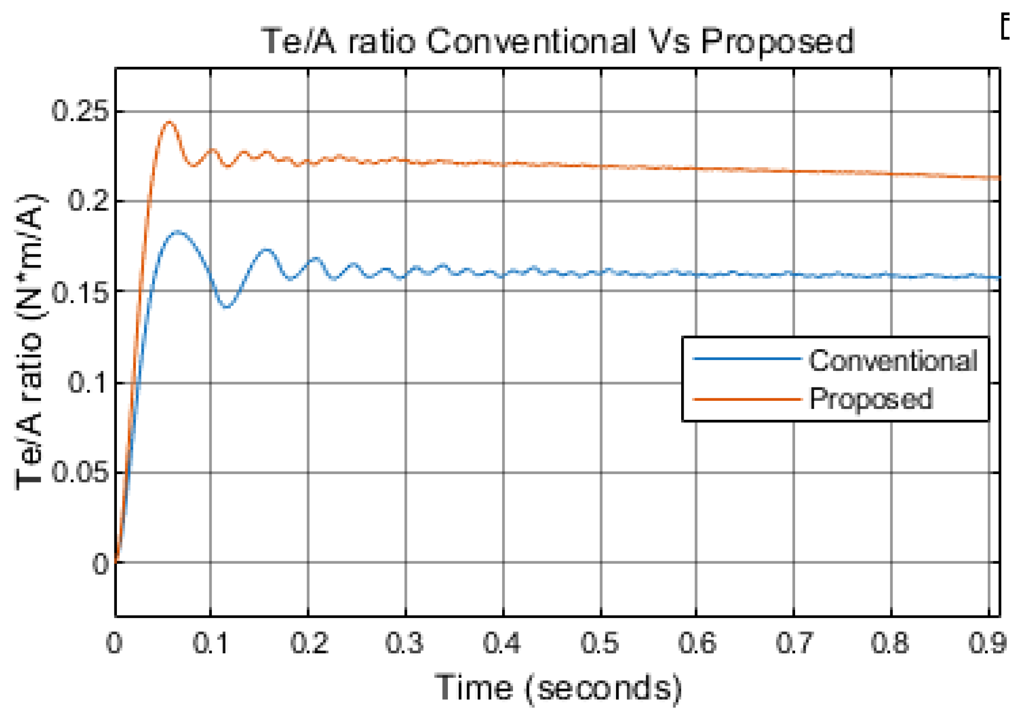
Figure 14.
Simulation results of current phase A w=1200 rpm Tl=0.1N*m.
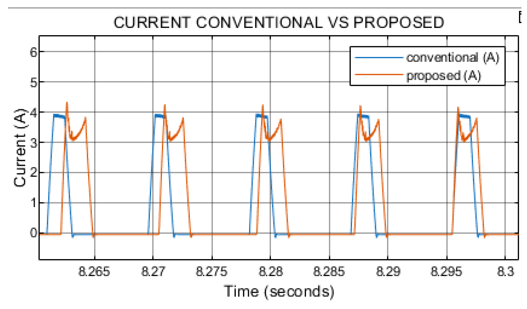
Figure 15.
Simulation results of speed w=1200 rpm Tl=0.1N*m.
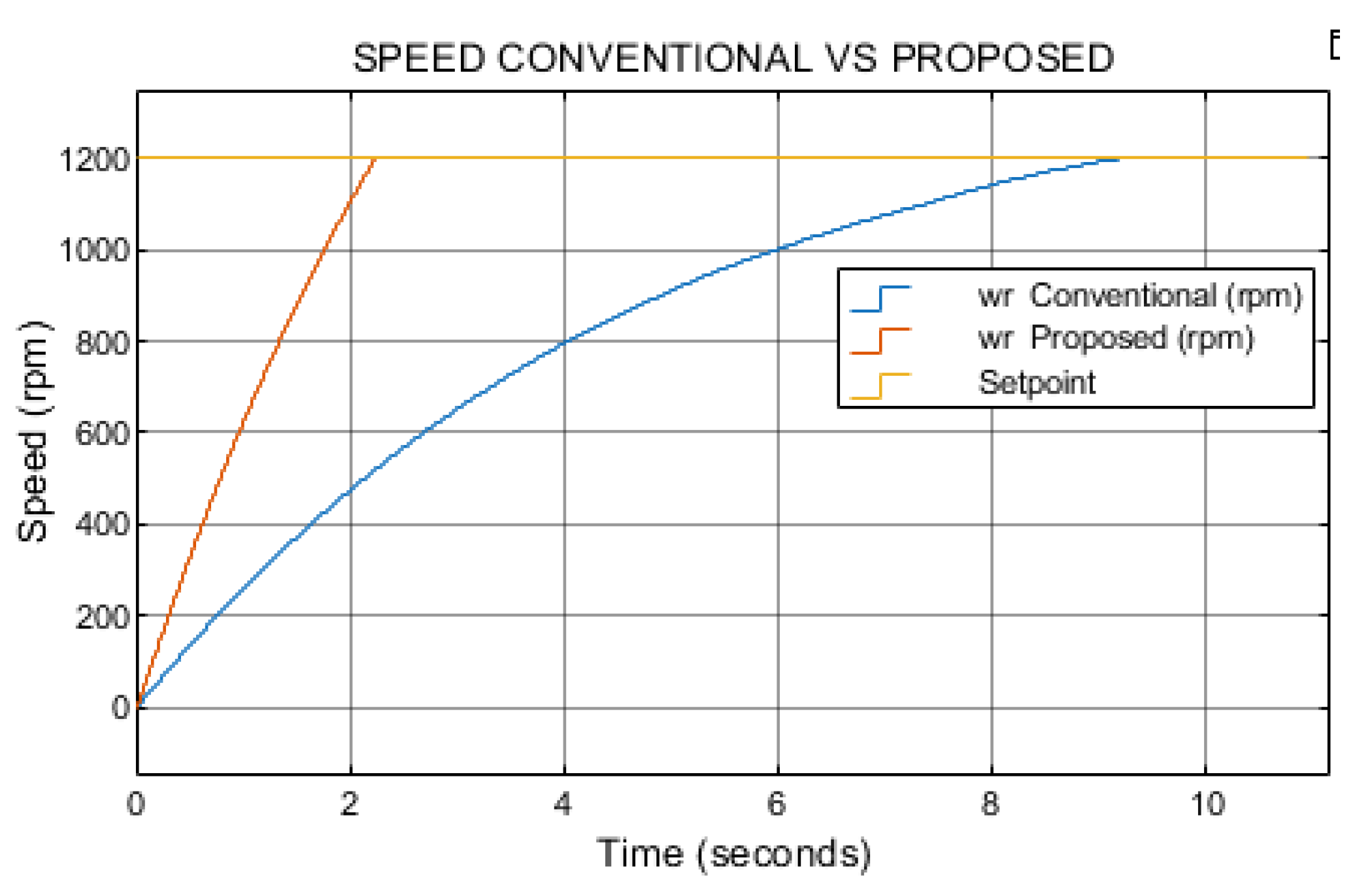
Figure 16.
Simulation results of torque w=1200 rpm Tl=0.1N*m.
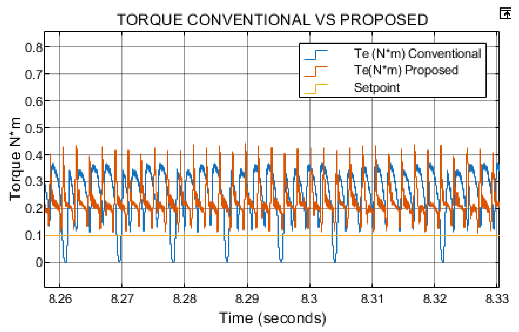
Figure 17.
Results of Te/A ratio Conventional Vs Proposed, w=1200 rpm Tl=0.1N*m.
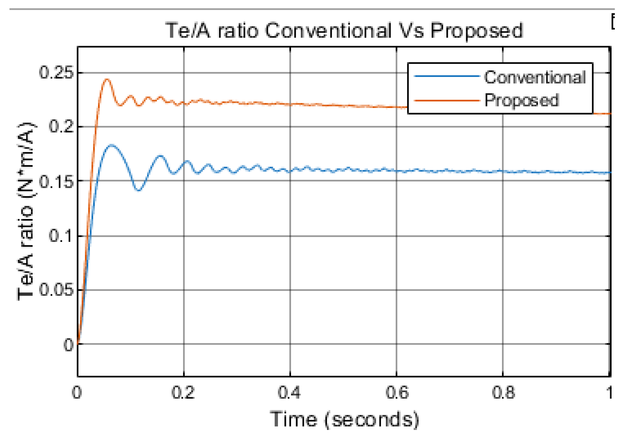
Figure 18.
Results torque tracking increasing the torque setpoint w=200rpm.
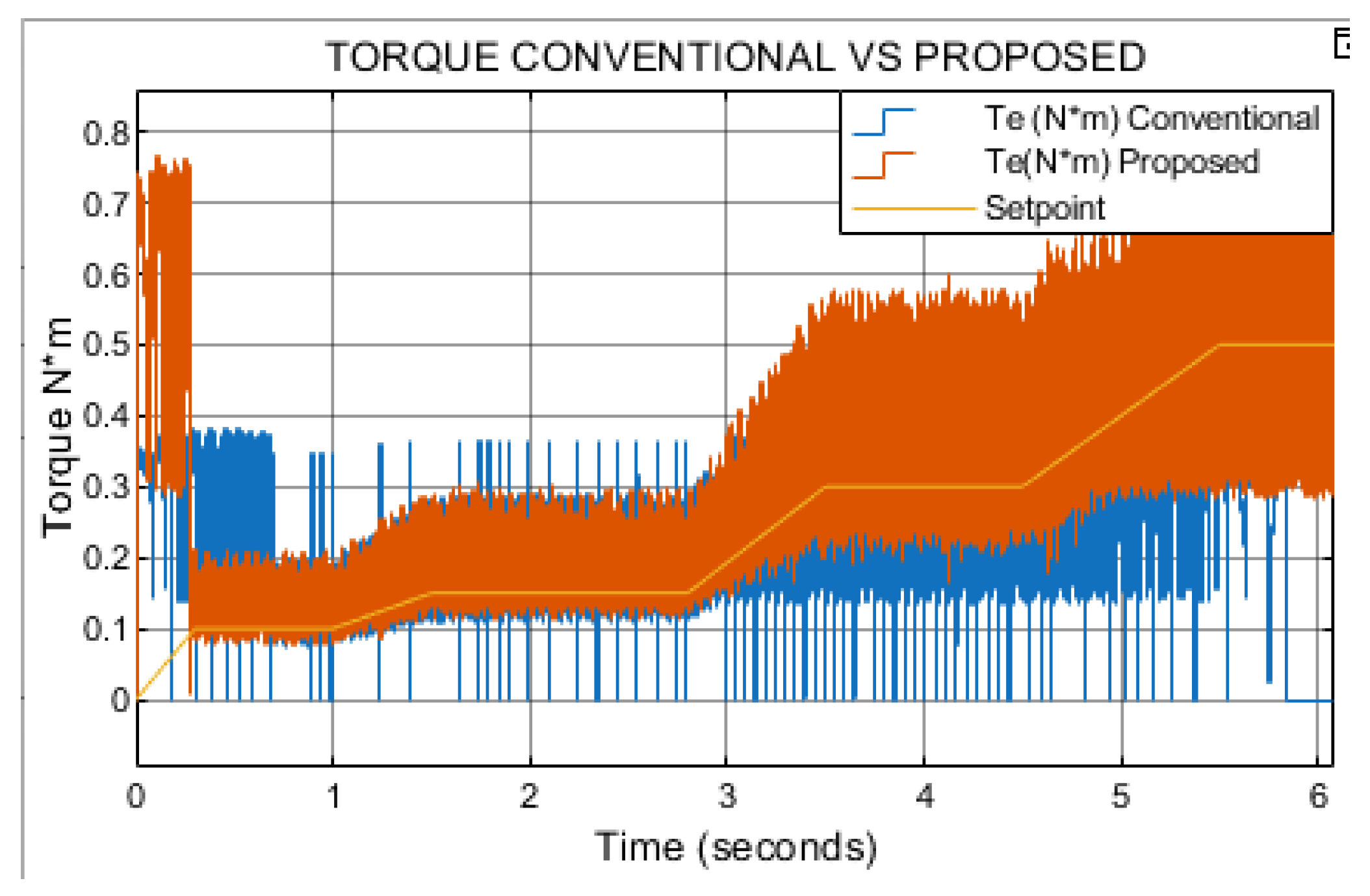
Figure 19.
Results torque tracking increasing the torque setpoint w=200rpm.

Figure 20.
PWM control block.
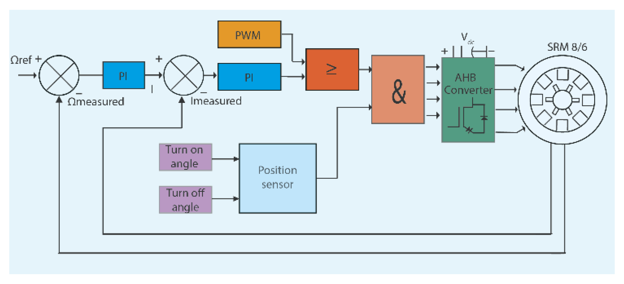
Figure 21.
Simulation results of speed FCS-MPC vs PWM control w=1200 rpm Tl=0.1N*m.
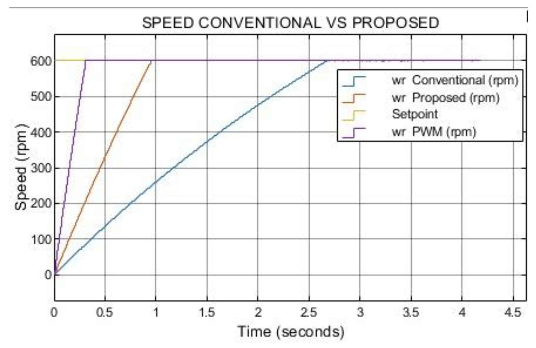
Figure 22.
Simulation results of speed tracking error FCS-MPC vs PWM control w=1200 rpm Tl=0.1N*m.
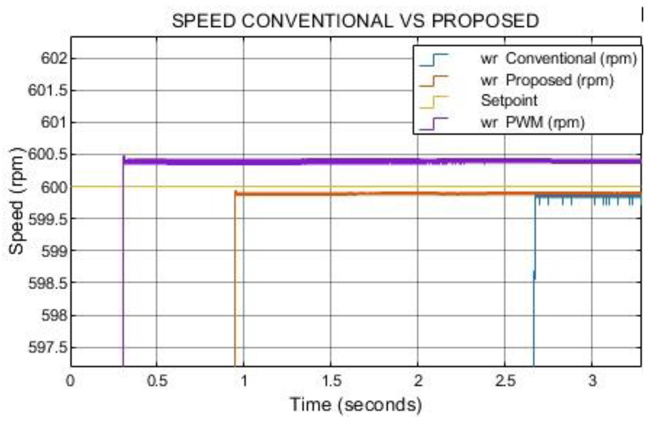
Figure 23.
Simulation results of torque comparing FCS-MPC with PWM w=600 rpm Tl=0.1N*m.
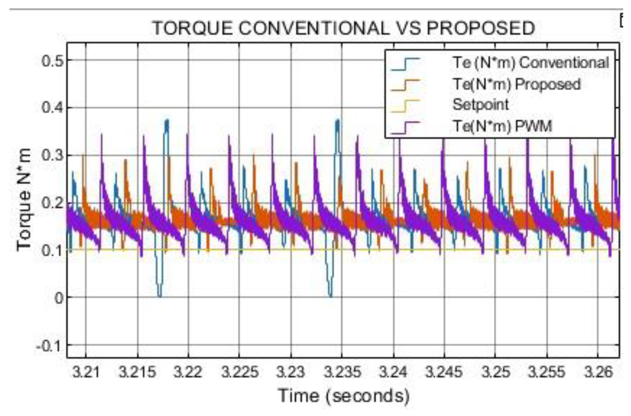
Table 1.
8/6 SRM Characteristics.
| Characteristic | Value |
|---|---|
| Stator resistance(Ohm) | 3.1 |
| Inertia(kg.m.m) | 0.0072 |
| Friction(N.m.s) | 0.01 |
| Unaligned inductance(H) | 5.9e-3 |
| Aligned inductance(H) | 23.6e-3 |
| Saturated aligned inductance (H) | 0.15e-3 |
| Maximum current(A) | 10 |
| Maximun flux linkage (V.s) | 0.486 |
Table 2.
Switching vectors for the conventional FCSMPC strategy.
| Voltage vectors | Switching states | αβ plane magnitude |
|---|---|---|
| V1 | (1,0,-1,0) | 2 ∠ 0° |
| V2 | (1,1,-1,-1) | 2.82 ∠ 45° |
| V3 | (0,1,0,-1) | 2 ∠ 90° |
| V4 | (-1,1,1,-1) | 2.82 ∠ 135° |
| V5 | (-1,0,1,0) | 2 ∠ 180° |
| V6 | (-1,-1,1,1) | 2.82 ∠ -135° |
| V7 | (0,-1,0,1) | 2 ∠ -90° |
| V8 | (1,-1,-1,1) | 2 ∠ -45° |
Table 3.
Switching sequence for the proposed FCSMPC strategy.
| Voltage vectors | Switching states | αβ plane magnitude |
|---|---|---|
| V1 | (1,1,-1,0) | 2 .23∠ 26.6° |
| V2 | (1,1,0,-1) | 2.23 ∠ 63.24° |
| V3 | (0,1,1,-1) | 2.23 ∠ 116.6° |
| V4 | (-1,1,1,0) | 2.23 ∠ 153.4° |
| V5 | (-1,0,1,1) | 2.23 ∠ 206.6° |
| V6 | (0,-1,1,1) | 2.23 ∠ 243.4° |
| V7 | (1,-1,0,1) | 2.23 ∠ 296.6° |
| V8 | (1,0,-1,1) | 2.23 ∠ 333.4° |
Table 5.
Computational efficiency conventional vs proposed.
| Metric | FCS-MPC Conventional | FCS-MPC Proposed |
|---|---|---|
| Total Steps | 400000 | 400000 |
| Step Size | 1e-5 | 1e-5 |
| Run Time (s) | 415.36 | 109.75 |
| Simulation Time (s) | 4 | 4 |
| Run/Sim Time Ratio | 103.84 | 27.44 |
Disclaimer/Publisher’s Note: The statements, opinions and data contained in all publications are solely those of the individual author(s) and contributor(s) and not of MDPI and/or the editor(s). MDPI and/or the editor(s) disclaim responsibility for any injury to people or property resulting from any ideas, methods, instructions or products referred to in the content. |
© 2025 by the authors. Licensee MDPI, Basel, Switzerland. This article is an open access article distributed under the terms and conditions of the Creative Commons Attribution (CC BY) license (http://creativecommons.org/licenses/by/4.0/).
Copyright: This open access article is published under a Creative Commons CC BY 4.0 license, which permit the free download, distribution, and reuse, provided that the author and preprint are cited in any reuse.


