Submitted:
07 August 2025
Posted:
07 August 2025
You are already at the latest version
Abstract
As an implantable life-support device, the magnetically levitated artificial heart demands a motor with high efficiency, low loss, contactless operation, and exceptional reliability. To overcome friction loss and torque ripple at high speed in conventional switched reluctance motors, this paper proposes an 18/15/6-pole double stator bearingless switched reluctance motor (DSBSRM) and its control system. The dual stator configuration spatially decouples torque and levitation fields, enhancing stability. A variable overlap angle TSF-PWM-DITC composite strategy suppresses torque ripple, while a new reaching law terminal sliding mode controller (NRLTSMC) ensures rapid, disturbance-resistant radial positioning. MATLAB/Simulink verification demonstrates significant reductions in torque, speed, and radial displacement fluctuations, offering a viable solution for next-generation artificial-heart drives.
Keywords:
magnetic levitation artificial heart
; torque control
; suspension control
; TSF
; SMC
1. Introduction
The development of the artificial heart has been a journey of innovation spanning more than two centuries, from early conceptualisations to the maturity of modern technology, each step of which has been the result of the ingenuity and hard work of scientists and medical practitioners. In the early days, the concept of “mechanical circulatory assistance” was proposed by
Julien Jean Cesar LeGallois in 1812 [1]. In 1937, Dr. Vladimir P. Demikhov attempted to develop a Total Artificial Heart in animal experiments in the USSR [2]. In 1953, American surgeon John Gibbon successfully performed the first intracardiac direct vision surgery using the heart-lung machine he invented, laying the foundation for the development of artificial organs [3].
Moving into the initial stage of development, the first left ventricular assist device was implanted by the team of legendary American surgeon Michael DeBakey in 1966. In 1969, Dr. Denton Cooley successfully used the Total Artificial Heart to sustain a patient's life for 64 hours, marking the beginning of the artificial heart technology's journey towards clinical application [4]. Subsequently, attempts at a permanent artificial heart were made. In the 1970s, under the leadership of Willem Kolff, the “father of artificial organs,” a team from the University of Utah developed the Jarvik-7, designed by Robert Jarvik. On December 2, 1982, retired dentist Barney Clark became the first person in the world to receive a “permanent” artificial heart [5].
In the technology iteration and optimisation phase, the HeartMate IP pulsatile left ventricular assist device was approved in 1984. In the late 1980s, Richard Wampler, the “father of the rotating artificial heart,” invented the Hemopump. In the 1990s, artificial heart technology began to spread, continuing to drive the field forward. In the 21st century, artificial heart technology has advanced rapidly. From the first generation of pulsatile pumps to the third generation of centrifugal pumps around 2010, significant improvements in performance have been achieved.
Early artificial hearts mostly used simple mechanically driven or pneumatic pumps, which have the disadvantages of large size, high risk of wear and tear failure, high damage to blood, high risk of infection, restricted movement, and noise. Additionally, patients need long-term anticoagulant therapy, which affects the overall quality of life and safety of patients. In the 21st century, with the development of science and technology, rotary blood pumps have gradually become the mainstream solution and are widely used in long-term adjuvant therapy due to their high efficiency, small size, and low blood damage. At the same time, in order to further improve the reliability and biosafety of implanted devices, magnetic suspension technology has been introduced into the design of blood pumps. The magnetic levitation artificial heart eliminates the friction and wear problems of traditional mechanical bearings and significantly improves operating life and patient comfort. The Maglev artificial heart achieves contactless rotation of the blood pump rotor through active electromagnetic suspension, effectively avoiding mechanical friction and lubrication problems, significantly improving the operational stability and biosafety of the device, and becoming the direction of development for the next-generation artificial heart. In the magnetic levitation artificial heart system, the motor is the core component of suspension and torque, and its performance directly affects the output efficiency and operational stability of the blood pump. Bearingless motors combined with torque and suspension control technology are the key to achieving highly reliable and contactless operation of the blood pump. Among them, bearingless switched reluctance motors (BSRM) show a broad application prospect in the field of biomedical drives due to their simple structure, good thermal stability, and non-dependence on permanent magnets.
The concept of BSRM was first proposed by scholars in 1989 and operates based on the "minimum reluctance principle"[6,7]. It enables the dual output of torque and radial force by superimposing the magnetic fields of control and suspension windings. Compared with traditional Switched Reluctance Motor, BSRMs effectively avoid the frictional heat and structural wear problems caused by mechanical bearings and are particularly suitable for high-speed and long-life operation scenarios [8,9,10,11]. However, traditional BSRMs still face issues such as significant coupling between torque control and suspension control, large torque ripple, and poor control accuracy, which limit their application in high dynamic response and high precision applications.
In order to enhance the overall performance of BSRMs, scholars both domestically and internationally have primarily conducted research in two areas: structural optimization and control algorithms [12,13]. In terms of structure, mainstream spatial magnetic circuit decoupling schemes include hybrid stator tooth structures, wide rotor tooth structures, double-stator structures, and composite rotor structures [14,15,16,17]. Among these, the double-stator structure has become a research hotspot in recent years due to its natural separation of suspension and torque flux paths and its excellent performance in magnetic decoupling and control independence. The double-stator bearingless switched reluctance motor (DSBSRM) constructed on this basis not only has high torque density but also can achieve high-precision suspension control, making it highly suitable for the performance demands of motors in magnetic levitation artificial hearts.
Regarding control strategies, traditional current chopper control and direct torque control (DTC) have been widely applied in switched reluctance motor systems [18,19]. Chopper control generates the target torque through hysteresis loop regulation of the winding current, but its calculation process is complex and its control accuracy is limited. The DTC method has become one of the mainstream control ideas by directly tracking the target torque signal without the need for an accurate mathematical model and exhibits good robustness [20,21]. However, DTC still suffers from large torque fluctuations and unstable dynamic responses. Direct Instantaneous Torque Control (DITC) is another advanced motor control strategy [22]. It is capable of real-time sampling of motor state quantities and quickly adjusting the PWM waveform according to the set control target to achieve fast motor control, making it suitable for applications sensitive to torque fluctuations.
To further suppress torque ripple and improve torque distribution performance, scholars have proposed the Torque Splitting Function (TSF) method [23]. This method achieves smooth torque transition between adjacent phases by dividing the period of the target torque, thereby reducing system vibration and noise. Although TSF has the advantages of simple implementation and good effect, the traditional TSF scheme ignores the effect of torque tracking error on ripple and still finds it difficult to meet the demand for high-precision control under strong dynamic conditions.
Meanwhile, to improve radial suspension performance, the PID controller is often used for closed-loop displacement control. However, the PID method is sensitive to system parameters and weak in disturbance rejection. Assuming there is no rotor eccentricity, it is still susceptible to modeling errors and external disturbances in actual operation. For this reason, advanced algorithms such as Sliding Mode Control (SMC), Model Predictive Control, and Adaptive Control are gradually being introduced into suspension force regulation control [24,25,26,27]. Among them, SMC shows better control stability than traditional PID due to its natural robustness to system uncertainties and disturbances. On the other hand, Terminal Sliding Mode Control (TSMC) introduces terminal convergence characteristics based on SMC, which can not only accelerate the system response speed but also significantly improve state tracking accuracy and anti-jamming capability[28]. This makes it suitable for popularizing the application of miniature and complex systems such as the magnetic levitation artificial heart.
To meet the above challenges, this paper designs a BSRM system based on a double-stator structure, proposes an improved TSF-PWM-DITC control strategy and a novel Finite-Time Robust Sliding Mode Control (NRLTSMC) scheme, and achieves dynamic optimization of the torque and suspension decoupling. The research work in this paper provides the theoretical foundation and technical support for the high-performance realization of the implantable blood pump electromagnetic drive system.
The main contents of this thesis are as follows: Chapter 2 introduces the electromagnetic structure, working principle, and modeling method of the DSBSRM; Chapter 3 proposes a TSF-PWM-DITC control strategy oriented towards high dynamic control requirements; Chapter 4 simulates and evaluates the performance of the proposed system using the Matlab/Simulink platform; Chapter 5 concludes the entire paper.
2. Structure and working principle of motor
The structure of the 18/15/6-pole DSBSRM is shown in Figure 1. It is an advanced motor technology that achieves contactless rotation of the rotor through a unique double stator structure and magnetic suspension principle.
The primary function of the inner stator is to generate suspension force, with each phase winding capable of producing suspension force to achieve magnetic suspension of the motor's rotor. This function relies on the basic principle of magnetic forces, namely the interactive fnditions, only the permanent magnets are active because their characteristics enhance the stability of the rotor. When the excitation windings are activated, they exert a force on the rotor that reverses the rotor's displacement, thereby generating suspension force. This suspension force is generated by controlling the current in the inner stator's excitation windings. By precisely controlling the magnitude and direction of the current, the suspension force can be accurately adjusted to maintain the rotor at a set position, achieving contactless suspension. This suspension method eliminates friction and wear in traditional bearings, improving the motor's efficiency and lifespan.
The main function of the outer stator is to generate torque force, with each phase winding capable of producing torque to drive the rotation of the motor's rotor. The outer stator is an 18-pole three-phase structure, with each phase alternating in operation. Torque generation is based on the "minimum magnetic reluctance principle," meaning that magnetic flux always tends to pass through the path of least magnetic reluctance. Through the DITC strategy, the motor can directly control the winding current to generate precise torque without relying on complex mathematical models. At the same time, the application of advanced control algorithms such as the TSMC further improves the system's dynamic response and robustness. In the design of the outer stator, by changing the current in the windings, the distribution of magnetic flux can be altered, creating a rotating magnetic field on the rotor. This rotating magnetic field interacts with the magnetic poles on the rotor to produce torque, causing the rotor to rotate. By precisely controlling the current in the outer stator windings, the generated torque can be accurately controlled, thereby achieving precise control over the motor's speed and direction. The design of the outer stator in this DSBSRM permits independent torque control, as the magnetic isolation ring on the rotor spatially separates the torque control from the force control of the inner stator. This structural decoupling simplifies and enhances the effectiveness of control.
In summary, the DSBSRM generates suspension force through the coordinated operation of the inner stator's permanent magnets and excitation windings, while the outer stator produces a rotating magnetic field by changing the current in its windings, thereby generating torque force to drive the rotation of the rotor. This design enables the motor to achieve contactless suspension and efficient torque control. Additionally, the design of the DSBSRM incorporates advanced control strategies that ensure stable suspension and efficient torque control.
The torque system and suspension system are independently controlled due to their good torque and suspension decoupling performance. Torque control is based on direct instantaneous torque control (DITC), and a sinusoidal three-phase torque sharing function (TSF) is designed according to the working condition of variable overlap angle. Then, the piecewise variable duty ratio pulse width modulation (PWM) is used to solve the problem of torque tracking performance. Combined with the actual working characteristics of the motor, different control signals are used in different intervals, and the formula of duty ratio and winding voltage under different working conditions is fitted to improve the control accuracy. The suspension force is controlled by double closed-loop direct instantaneous suspension force control (DIFC). Because the suspension force of 18/15/6 pole DSBSRM is controlled by the combination of permanent magnet and excitation, the permanent magnet and electromagnetic conversion occur when the rotor is eccentric, and the instability of the system increases. Therefore, to reduce the rotor radial displacement pulsation and improve the robustness and dynamic response of the suspension system, the fast TSMC is introduced to effectively eliminate the chattering, and a new sliding mode reaching law (RL) is designed. New sliding mode RL can reduce chattering while keeping high approaching speed, the control ability is further improved. A new type of sliding mode control RL, with its unique nonlinear design, can ensure that the system state reaches the sliding mode surface quickly while reducing the chattering caused by the fast switching of control signals. This RL introduces a nonlinear term in the control strategy, which can be dynamically adjusted according to the change of the system state, enabling a smoother transition as the system approaches the sliding mode surface, avoiding the drastic state changes and high-frequency chattering common in traditional SMC. In addition, due to the property of finite-time convergence, the RL is able to ensure that the system state reaches the desired state within a predetermined time or even a shorter period of time, which improves the response speed of the system. The design of the RL also takes into account the uncertainties in the system parameters and the external disturbances, which enhances the system's ability to resist these uncertainties through the intrinsic robustness of the SMC. Together, these factors make the proposed RL perform well in improving the speed and accuracy of the radial response position control, significantly reducing the chattering that may occur in the SMC, and thus improving the stability and reliability of the system operation while ensuring the control accuracy.
Since the controller parameters have a significant indigenous influence on the motor performance, the optimal algorithm is adopted to adjust the tuning parameters. In recent years, genetic algorithm, particle swarm optimization (PSO), grey wolf optimization algorithm (GWOA), suburban wolf optimization algorithm (SWOA), and other optimization algorithms are used to obtain the optimal parameters in various control systems. The comprehensive performance of these algorithms, including convergence, efficiency, and local optimality prevention, needs to be further improved [29]. GWOA has advantages in local search ability, solution accuracy, and convergence. In addition, GWOA has better operability and faster running speed based on objective function parallel computing. Therefore, reference [30] introduced GWOA to adjust its parameters. In the suspension control of DSBSRM, GWOA is used to optimise TSMC parameters such as switching gain and linear gain. The goal is to improve the dynamic response of the system, reduce the eccentricity and radial displacement fluctuations of the rotor, thus ensuring the radial stability of the rotor and improving the performance and robustness of the overall motor control system under various operating conditions.
3. Control Systems
3.1. Torque control
In this paper, the torque control adopts DITC combined with variable duty ratio PWM and TSF. Through TSF, the turn-on angle and turn-off angle can be reasonably allocated, and the specific reference torque can be output, so that the motor can be carried out smoothly during commutation, thereby inhibiting torque ripple. Commonly used distribution functions are linear, sine, cosine, cubic, and exponential. Among them, the cosine type is more suitable for nonlinear system control and can suppress torque ripple better than other distribution functions. The cosine torque distribution function formula is as follows:
Where: is the rotor position angle, and are the phase turn-on angle and turn-off angle, is the dynamic overlap angle.
The control system was designed to adjust these angles based on the operating conditions of the motor to optimise performance. Figure 2 shows the sinusoidal torque distribution waveform.
The traditional TSF is used to control torque ripple with a fixed overlap angle. However, a fixed overlap angle cannot adapt to changes in operating conditions, which may lead to additional torque fluctuations. To solve this problem, this study introduces a TSF control strategy with a variable overlap angle that dynamically adjusts the commutation timing according to the real-time operating conditions. This dynamic adjustment optimises torque distribution and effectively reduces the torque fluctuation. Specifically, at low speeds, the overlap angle is increased to prolong the conduction time of the two phases to make the commutation process smoother; while at high speeds, the overlap angle is decreased to prevent excessive power loss due to prolonged overlap time. In this structure, is calculated as follows:
Where: is the k-1 correlation angle. is the angle of the k phase corresponding to the opening angle of the k phase, and is the angle when the k phase stops working. is the number of rotors.
The opening angle is set as a constant, and the k phase exists at :
The position of is determined by detecting the current, and the value of calculated by the formula (2) and (3) is brought into formula (1) TSF control to realize the variable overlap angle control of TSF. When the working condition changes, the current overlap angle will also change to ensure the rationality of the distribution during the commutation period. To avoid negative torque, also needs to satisfy the following:
Where: is the pole distance of the motor rotor.
In addition, the torque signal in the traditional control system is a discrete signal obtained at a certain sampling frequency, so the switching control signal received by the power converter will lag behind the change of torque. If the torque changes rapidly in the control process, it often exceeds the hysteresis interval, resulting in a large torque ripple. Since the torque tracking is affected by the control frequency and winding voltage, and the control frequency of the system is difficult to change in the actual situation, it is necessary to suppress the torque ripple generated by the winding voltage. Therefore, in order to improve torque tracking performance and reduce torque fluctuations, this study proposes the use of Pulse Width Modulation (PWM) with variable duty cycle. The PWM dynamically adjusts the duty cycle according to the operating conditions of the motor to optimise current tracking and reduce torque fluctuations. During commutation, the PWM duty cycle is automatically adjusted as the operating conditions change to ensure that the applied voltage avoids sudden changes in current, thus effectively reducing torque fluctuations. Moreover, by reasonably distributing the positive and negative voltages during the control period, the PWM can smooth the rise and fall rates of the current, further reducing ripple generation.
Due to the nonlinear characteristics of BSRM, the smooth electromagnetic torque cannot be obtained by injecting a constant current into each phase, and the electromagnetic torque of each phase changes with the rotor position and phase current. Without considering the mutual inductance between windings, according to the principle of virtual displacement, the electromagnetic torque of phase k at rotor position and phase current can be expressed as:
Where: is the electromagnetic torque of phase k. is the rotor position angle. is magnetic co-energy, and its expression is:
Where: is the k-phase flux linkage; is the k-phase inductance; is a function of rotor position and phase current.
When the chain saturation effect is neglected, is independent of the phase current and can be simplified to a function about the position, and according to the linearized model of the inductor the k-phase electromagnetic torque approximation formula can be obtained as:
The formula describes the relationship between torque, current, and rotor position.
Where: D is the PWM duty cycle.
The force generation model for phase k can be expressed as:
Where: r is the radial position of the motor.
The k-phase electrical equilibrium equation of BSRM is:
Where: and are the voltage and resistance of the k-phase winding, respectively. Usually, the winding resistance is small, and the winding voltage drop can be ignored. Bring formula () into Equation 11 to:
Where: is the rotor speed, and for Equation 12 solving a differential equation:
Where: is the k-phase current at moment . Assuming a sampling step of , then:
Where: is the current variation in , and the value is usually small, so the exponential part of Equation 14 is approximately 1, then:
Where: is the back electromotive force at time.
When using PWM control, the voltage signal is a pulse signal within a cycle, the average value of which is affected by the duty cycle D. The average voltage is given by the following equation.
Where: is the maximum voltage.
By adjusting the duty cycle D, the average voltage can be adjusted, thus controlling the rate of increase or decrease of the current, avoiding sudden current changes and reducing torque fluctuations.
From Equation 15, we can see that the rate of change of phase current at is related to once. As the speed increases, the phase current change rate decreases and the current tracking ability decreases, so the higher the speed, the less ideal the torque control effect. In this regard, the variable duty ratio PWM control is introduced, and the duty ratio D () is selected according to the speed and reference torque, to distribute the proportion of ' 1 'and ' -1 'in a control cycle.
For 18/15/6 pole BSRM, the PWM control signal is shown in Figure 3. In the figure, and are the PWM signals of the upper switch and the lower switch, respectively, and is the sampling time. , , and are duty cycles and satisfy ,, and .The corresponding formula between phase inductance and rotor angle is shown in Figure 4 .
The analytical function corresponding to the inductance curve in Figure 4 is:
Where: is the slope of the inductance linear variation region. The value of is:
To obtain larger dynamic torque, the turn-on angle is usually designed before , and the turn-off angle is designed before the maximum inductance arrives, that is, within . Different duty cycles are set with as the dividing point. Combined with (12), (13), and Figure 4, when the excitation is conducted, the change rate of phase inductance in the range of + is close to 0, and then the current rises rapidly. A smaller voltage should be given to alleviate the rising speed, so the duty cycle should be set smaller. The current change rate in is small as the inductance change rate increases, so should be set slightly larger. When demagnetizing, the rate of change of current in the interval with increasing inductance is slower, so the setting should be smaller.
Combining a variable overlap angle with pulse width modulation (PWM) control can further optimise torque distribution and reduce torque fluctuations. Assuming that the torque sharing function (TSF) is adjusted based on the rotor position, the overlap angle can be dynamically adjusted according to the following equation for different operating conditions:
By reasonably selecting the duty cycle D and the overlap angle, the current waveform can be optimised to reduce current discontinuities, thereby effectively reducing the torque fluctuations.
3.2. Suspension control
DIFC takes the suspension force as the control object and adds the suspension force closed-loop based on the traditional square wave control to form a double closed-loop control. For the value of the suspension force, three directions with an interval of 120° are taken according to the structural characteristics, as shown in Figure 5. To avoid the coupling between each direction and simplify the control, the displacement in each direction is controlled item by item.
To improve the robustness and dynamic response of the control system, an improved fast Terminal SMC is designed to replace the PID controller.
From the literature [29] we know that the coupling between the radial suspension forces of the motor is very small, and the suspension forces between the directions can be regarded as radial force subsystems that do not affect each other, so the establishment of a single degree of freedom mathematical model can be deduced to the whole suspension system mathematical model, the nonlinear motion model is:
Where: is the suspension force, m is the rotor mass, x is the radial displacement, and is the external environmental disturbance.
Take the tracking error as the difference between the reference displacement and the actual displacement .
For the design of the SMC, the sliding mode plane s is selected as the first step as follows:
Derive the sliding mode plane to get:
To achieve fast convergence of the system state in a finite time, the terminal sliding mode function is selected as follows:
Where: , , and are both positive odd numbers.
When the system state enters Terminal sliding mode, =0, then:
The general form of the reaching law can be expressed as:
Where: and are the switching gain and linear gain are greater than 0 respectively. is the sign function.
According to the above formula, the time required to get to the Terminal sliding surface is:
The second step of the sliding mode controller design is designed to make the terminal sliding mode surface converge to zero in a finite time, a suitable RL is designed so that the error states and can reach the equilibrium point. The proposed NRL is described below:
Where: and are the switching gain and linear gain are greater than 0 respectively.
In addition, .
The absolute value of the error is added to the pure exponential approach term in RL to increase the approach speed. In SMC, the conventional RL employs the sign function to indicate whether the system state reaches the sliding mode surface. The problem is that when the system state is close to the sliding mode surface, the discontinuity of the sign function may lead to an abrupt change of the control signal, which triggers high-frequency oscillations. To solve this problem, a sigmoid function is introduced, which is a smoothing function that can effectively reduce the chattering caused by sudden changes in the control signal. The graphs of the two functions are shown in Figure 6, and the trajectory of the sigmoid function converges to a set around the equilibrium point, which is more in line with the needs of practical control applications.
Increasing the parameter λ can accelerate the convergence of the system state. However, relying solely on the sigmoid function may still cause chattering due to significant fluctuations in the control input resulting from overly fast convergence. By introducing the sigmoid function, not only can the convergence speed be improved by adjusting λ appropriately, but also the amplitude of chattering can be controlled by the smooth sigmoid function to avoid excessive fluctuation of the control input.
To verify stability issues, we chose the Lyapunov function . According to Lyapunov stability theory, it should satisfy:
Then:
Where: and are positive numbers, and and are always non-negative numbers, so . Then the designed SMC is asymptotically stable under the Lyapunov function.
Combining Equation 21、27 and Equation 29 we get:
Then get the suspension given value :
As shown in Figure 7, the suspension force control diagram shows that is the given value of suspension force, and F is the actual value of suspension force. The error of the two is the input of the hysteresis controller, and S(A) is the switching signal of suspension winding, which is the output of the control area. The discrete two-point control method is applied to the controller. When , the controller output is 0, the power converter is closed, the current decreases, and the suspension force decreases. When the suspension force decreases to , the controller output 1, the power converter is turned on, the current increases, and the suspension force increases. Until , the controller output 1 again, and the suspension force decreases, which forms a cycle to realize the stable control of the suspension force.
3.3. Control block
Combined with the above analysis, simulation analysis is carried out based on MATLAB/Simulink. The schematic diagram of constructing TSMC according to Equation 32 is shown in Figure 8. Build 18/15/-pole DSBSRM control simulation model as shown in Figure 9.
Torque control: a double closed loop is formed by speed control and torque control, in which the outer ring speed torque control and the inner ring torque control. The rotor position angle is obtained by the rotor position detection module to calculate the actual speed , which is different from the ideal speed . The PID module is converted to the reference total torque , and then the TSF torque distribution module is outputted to , where is the torque of three phases. The obtained is different from the actual torque. The control signal is output by hysteresis control, and then the signal is processed by PWM with a variable duty ratio, to control the conduction and shutdown of the power converter and realize stable and continuous torque output. For the duty cycle in the demagnetization state, the control effect is better when the duty cycle d is small, so the fixed value is 0.15. For duty cycle , in the actual control is also affected by the reference torque and speed, so the trial-and-error method is used to determine the value of ,. Firstly, a coarse-grained search is conducted with a step size of 5% to quickly determine the range of duty cycles that minimise torque fluctuations. Subsequently, within this range, a fine-grained search with a step size of 1% is performed to ultimately select the optimal duty cycle. The search results are shown below:
However, after using variable duty ratio PWM modulation, different duty ratios under different working conditions also have more accurate requirements for winding voltage. Therefore, to ensure the control effect of the system, the most reasonable voltage values under different working conditions are determined by the trial-and-error method. Firstly, a coarse-grained search with a step size of 5% is conducted to quickly determine the range of voltage values that minimise torque fluctuations. Subsequently, within this range, a fine-grained search with a step size of 1% is performed to ultimately select the optimal voltage value. The voltage values under medium-low speed and light load are obtained by sorting out the results:
Suspension control: double closed-loop control is also adopted. The outer ring is the rotor eccentric displacement control, and the inner ring is the suspension force control. The displacement deviation in ,, and directions is obtained by the rotor radial displacement detector, which is different from the ideal displacement ,, and . The difference value is output by TSMC as reference suspension force , , and , and then is compared with the actual suspension force ,, and obtained by the suspension force prediction module. The difference is output as the switching signal through dual hysteresis control, which controls the conduction and switching of the power converter to achieve stable suspension.
The 18/15/6-pole DSBSRM parameter used in the simulation is shown in Table 1.
4. Simulation analysis
To verify whether the above control method can achieve the designed control effect, the simulation experiment was conducted on the MATLAB/Simulink platform, and a control simulation model for the 18/15/6-pole DSBSRM was built.
For the simulation of motor torque control, to highlight the advantages of the improved torque control method, the direct torque control of traditional TSF is used as the simulation experimental control group. With the ideal rotational speed as the experimental variable, other independent variables are set. The opening angle is set as , the turn-off angle is set as 8.5° after calculation, and the overlap angle of the control group is set to a fixed value.
Figure 10 is the velocity waveform comparison chart under the control of the two methods. The initial rated speed is 700 r/min, and then the rated speed is modified to 1000 r/min and 800 r/min in 1 s and 2 s, respectively. The experimental data are listed in Table 2.
Maximum speed difference at steady
state
(r/min)
From Table 2, we can see that under the ideal speed of 700 r/min, when the speed reaches a stable condition, the speed curve under the improved TSF-PWM-DITC fluctuates less than that under the conventional TSF-DITC, as shown in Figure 10. Compared to the traditional TSF-DITC, the maximum speed difference of the improved TSF-PWM-DITC is 47.7% lower.
At the ideal speed of 1000 r/min, we can see from Figure 10 that the speed stability of the improved TSF-PWM-DITC is better than that of the traditional TSF-DITC. The maximum speed difference of the improved TSF-PWM-DITC compared to the traditional TSF-DITC is reduced by 67.85%.
When the ideal speed drops to 800 rpm, the Improved TSF-PWM-DITC works better than the conventional TSF-DITC. It keeps the speed more stable. The maximum speed difference in the improved TSF-PWM-DITC is 56% less than in the conventional TSF-DITC. When the speed is steady, the improved TSF-PWM-DITC can limit excessive speed changes. It also makes the speed output more accurate.
Combined with Figure 10 and Table 2, we can see that the improved TSF-PWM-DITC slightly lags behind the traditional TSF-DITC in steady-state arrival time. At the ideal speed of 700 r/min, the time to reach steady-state lags by 0.00168 s. At the ideal speed of 1000 r/min, the steady-state time lags by 0.0025 s. At the ideal rotational speed of 800 r/min, the steady-state time lags by 0.0025 s. We can conclude that the dynamic responsiveness of the improved TSF-PWM-DITC is slightly lower than that of the traditional TSF-DITC, but the reduction is small and the operation is not affected for a long time, which can still reflect the advantages of the direct control method.
We further explore the control effect of the improved control method on torque and current. Figure 11 shows the total torque and phase separation torque at different times in the simulation process. To further highlight the improvement of torque tracking, the comparison diagram of different time reference torque and actual control torque is added. We can see that the improved TSF-PWM-DITC is superior to the traditional TSF-DITC in suppressing phase current ripple and torque ripple.
To quantitatively analyze the torque, the total torque data in Figure 11 are measured by Equation 31, is the torque ripple rate.
Where: , , and are the maximum, minimum, and average resultant torque in the sampling interval.
Under rated speed of 700 r/min, 1000 r/min, and 800 r/min, the torque ripple P of the improved TSF-PWM-DITC is 0.4105, 0.3103, and 0.4462, respectively. The torque ripple P of the traditional TSF-DITC is 1.0753, 1.0758, and 0.9965. We can see that the torque ripple of the improved control method is significantly reduced, and the peak torque during commutation is significantly reduced. The improved control method has a better torque ripple suppression effect than the traditional DITC control method.
In addition, to further show the control effect of the PWM control method, Figure 11 shows that the improved TSF-PWM-DITC exhibits significantly better tracking ability of the reference torque compared to the traditional TSF-DITC. The change in actual torque per unit sampling interval under TSF-PWM-DITC control is smaller and more accurate, thus significantly reducing torque ripple.
Suspension control based on traditional exponential reaching law SMC controller is selected as suspension simulation control group. In the design of NRLTSMC controller parameters, with the rotor radial stability and displacement error as the target, the optimal values of the parameters are found using the Grey Wolf Optimization Algorithm. The relevant parameter values are obtained as: , , , , . For external disturbance force according to the literature [31] torque part of the suspension does not affect the three directions of external interference and is relatively stable, so set to a fixed value. For the simulation of the suspension control, the and directions are used as the experimental objects. The rotor ideal deviation displacement and are initially set to 0 mm and adjusted to 0.2 mm and 0.1 mm respectively at 2 s. The initial deviations and are set to 0.15 mm and 0.2 mm, respectively.
Figure 12 is the waveform of direction displacement simulation results under two control methods. Figure 13 is the waveform of direction displacement simulation results under two control methods. From the control comparison simulation results in Figure 12 and Figure 13, it can be seen that:
In the direction. At 0 s, the time to reach stability was 2.0085 s under NRLTSMC control and 2.0103 s under SMC control. At 2 s, the time to reach stability was 0.01131 s under NRLTSMC control and 0.014491 s under SMC control. In the X2 direction. At 0 s, the time to reach stability was 0.012975 s under NRLTSMC control and 0.017257 s under SMC control. At 2 s, the stability time under NRLTSMC control was 2.0078 s, and the stability time under SMC control was 2.0096 s. In the stable stage, the tracking ability under NRLTSMC control is significantly better than that of SMC, and the steady-state displacement of the rotor under NRLTSMC control is stable near the reference value. In the X1 direction, the maximum overshoot is mm under NRLTSMC control and mm under SMC control. In the X2 direction, the maximum overshoot is mm under NRLTSMC control and mm under SMC control.
The NRLTSMC controller is better than SMC for radial displacement control. It responds faster and can quickly correct rotor offset and reduce ripple. With NRLTSMC, the system tracks displacement very well, which enhances control accuracy.
5. Conclusion
In this paper, a DSBSRM for a magnetically levitated artificial heart system is designed, and a corresponding torque and suspension control strategy is proposed. The separation of torque and suspension magnetic circuits is achieved through structural decoupling, which provides a basic guarantee for the stable torque and high-precision suspension of the artificial heart blood pump. In terms of control, this paper introduces a variable overlap angle TSF-PWM-DITC control strategy to suppress torque ripple and combines it with NRLTSMC to improve the dynamic response and anti-interference capability of the suspension system. Simulation results show that the system can effectively reduce speed fluctuation and torque jitter, stabilize the radial position of the rotor, and meet the stringent requirements of the artificial heart for smooth and safe motor operation. This study provides useful theoretical support and technical reference for the design of motor drive and control systems in magnetic levitation artificial hearts and has good engineering application prospects.
Author Contributions
Conceptualization, Chuanyu Sun and Ning Han; methodology, Tao Liu, Ning Han and Chuanyu Sun; software, Tao Liu; data curation, Chuanyu Sun, Ning Han and Chunmei Wang; writing—original draft preparation, Chuanyu Sun and Ning Han; writing—review and editing, Chuanyu Sun, Ning Han, Tao Liu; supervision, Chuanyu Sun; project administration, Chuanyu Sun. All authors have read and agreed to the published version of the manuscript.
Funding
The research was sponsored by Nature and Science Foundation of China (Project No. 51774193), Nature and Science Foundation of Shandong Province (Project No. ZR2019MEE068), and High-level Talents (Doctor) Research Project of Linyi University (Project No. Z6122065), Key R&D Program of Shandong Province for Innovative Technology Enterprises (Project No. 2024TSGC0863).
Data Availability Statement
The original contributions presented in the study are included in thearticle/supplementary material, further inquiries can be directed to the corresponding author.
Conflicts of Interest
The authors declare no conflicts of interest.
References
- Hogness J, VanAntwerp M. The artificial heart. 1st ed. Washington, D.C.: National Academy Press; 1991.
- Konstantinov, IE. At the cutting edge of the impossi ble: a tribute to Vladimir P. Demikhov. Tex Heart Inst J. 2009;36(5):453-458.
- Bartlett, RH. John H Gibbon Jr Lecture. Extracorpor eal life support: Gibbon fulfilled. J Am Coll Surg. 2014;218(3):317-327.
- Gaitan BD, Thunberg CA, Stansbury LG, Jaroszewski DE, Arabia FA, Griffith BP, Grigore AM. Develop ment, current status, and anesthetic management of the implanted artificial heart. J Cardiothorac Vasc Anesth. 2011;25(6):1179-1192.
- Grubin, D. The Mysterious Human Heart. The Replace ment Heart. Jarvik-7 | PBS [Internet]. Pbs.org. 2007 [5 July 2014]. Available from: http://www.pbs.org/wnet/ heart/episode1/replacement.html.
- Fukao, T. (2000). The evolution of motor drive technologies: Development of bearingless motors. In Proceedings of the Third International Power Electronics and Motion Control Conference (IPEMC 2000) (Vol. 1, pp. 33–38). Beijing, China.
- Xiang, Q. , Ou, Y., Peng, Z., & Sun, Y. (2023). Review on self-decoupling topology of bearingless switched reluctance motor. Energies, 16(8), 3492. [CrossRef]
- Xu, Z. , Ding, J., Fan, Z., & Zhang, F. (2023). Characteristics analysis of a novel 12/8 double stator bearingless switched reluctance motor. Journal of Electrical Engineering & Technology, 18(1), 347–357. [CrossRef]
- Zhou, Y. , Jiang, J., Hu, P., & Yuan, Y. (2021). A novel dual-channel bearingless switched reluctance motor. IEEE Access, 9, 122373–122384.
- Zhang, W. , & Zhu, H. (2017). Radial magnetic bearings: An overview. Results in Physics, 7, 3756–3766. [CrossRef]
- Wang, H. , & Li, F. (2020). Design consideration and characteristic investigation of modular permanent magnet bearingless switched reluctance motor. IEEE Transactions on Industrial Electronics 67(6), 4326–4337. [CrossRef]
- Al-Amyal, F. , & Szamel, L. (2022). Research on novel hybrid torque sharing function for switched reluctance motors. IEEE Access 10, 91306–91315.
- Xia, Z. , Bilgin, B., Nalakath, S., & Emadi, A. (2021). A new torque sharing function method for switched reluctance machines with lower current tracking error. IEEE Transactions on Industrial Electronics 68(11), 10612–10622. [CrossRef]
- Hao, W. , Hao, J., Wang, Z., & Hao, Y. (2022). Decoupling characteristics and torque analytical model of sharing-suspension-windings bearingless switched reluctance motor considering flux-linkage saturation. Sustainability, 14, 24, 16633. [CrossRef]
- Sun, C. , Yang, H., Han, S., Ding, H., Li, J., & Han, N. (2021). Control system design for 16/6/8 double-stator bearingless switched reluctance motor. Mathematical Problems in Engineering, 2021, 4727917. [CrossRef]
- Sun, C. , Li, J. , Zhuang, P., & Han, China., N. (2019). Design and analysis of a novel 24-phase bearingless switched reluctance motor. In Proceedings of the 2019 IEEE 3rd International Electrical and Energy Conference (CIEEC) (pp. 451–455). Beijing, China. [Google Scholar]
- Zhang, T. , Chen, J., & Zhu, W. (2021). Suspension performance analysis on the novel hybrid stator type bearingless switched reluctance motor. IEEE Transactions on Magnetics 57(6), 1–4. [CrossRef]
- Oloo, J. , & Laszlo, S. (2025). Torque ripple minimization for switched reluctance motor drives based on Harris Hawks–Radial Basis Function approximation. Energies, 18(4), 1006. [CrossRef]
- Takemoto, M. , Chiba, A. , & Fukao, T. (2000). A new control method of bearingless switched reluctance motors using square-wave currents. In Proceedings of the 2000 IEEE Power Engineering Society Winter Meeting (Vol. 1, Singapore, Singapore); pp. 375–380. [Google Scholar]
- Cao, X. , Zhou, J., Liu, C., & Deng, Z. (2017). Advanced control method for a single-winding bearingless switched reluctance motor to reduce torque ripple and radial displacement. IEEE Transactions on Energy Conversion, 32(4), 1533–1543. [CrossRef]
- Cao, X. , Sun, Q., Liu, C., Zhou, H., & Deng, Z. (2017). Direct control of torque and levitation force for dual-winding bearingless switched reluctance motor. Electric Power Systems Research, 145, 214–222. [CrossRef]
- Yong, C. , & Xiao, C. (2019). Hysteresis-pulse width modulation direct instantaneous torque control of switched reluctance motor based on fuzzy adaptive PID. Motor and Control Applications, 46(1), 40–47.
- Yang, R. , Wang, X., Huang, Z., & Ma, Y. (2025). Torque ripple minimization control of switched reluctance motor based on online torque sharing function. IEEE Transactions on Power Electronics 40(4), 4878–4888. [CrossRef]
- Sun, X. , Wang, N., Yao, M., & Lei, G. (2025). Position sensorless control of SRMs based on improved sliding mode speed controller and position observer. IEEE Transactions on Industrial Electronics 72(1), 100–110. [CrossRef]
- Sun, X. , Feng, L., Zhu, Z., Lei, G., Diao, K., Guo, Y., & Zhu, J. (2022). Optimal design of terminal sliding mode controller for direct torque control of SRMs. IEEE Transactions on Transportation Electrification 8(1), 1445–1453. [CrossRef]
- Sun, X. , Zhu, Y., Cai, Y., Yao, M., Sun, Y., & Lei, G. (2024). Optimized-sector-based model predictive torque control with sliding mode controller for switched reluctance motor. IEEE Transactions on Energy Conversion, 39(1), 379–388. [CrossRef]
- Jie, G. , & Gao, B. In (2019). Axial switched reluctance wheel motor control system with the direct torque based on fractional order sliding mode. In Proceedings of the 2019 Chinese Control and Decision Conference (CCDC) (pp. 1891–1895). Nanchang, China: IEEE.
- Sun, X. , Feng, L., Diao, K., & Yang, Z. (2021). An improved direct instantaneous torque control based on adaptive terminal sliding mode for a segmented-rotor SRM. IEEE Transactions on Industrial Electronics, 68, 11, 10569–10579.
- Feng, L. , Sun, X., Tian, X., & Diao, K. (2022). Direct torque control with variable flux for an SRM based on hybrid optimization algorithm. IEEE Transactions on Power Electronics 37(6), 6688–6697. [CrossRef]
- Sun, X. , Jin, Z., Cai, Y., Yang, Z., & Chen, L. (2020). Grey wolf optimization algorithm based state feedback control for a bearingless permanent magnet synchronous machine. IEEE Transactions on Power Electronics 35(12), 13631–13640.
- Han, N. , Sun, C., Li, J., Yang, H., & Han, S. (2022). Design and characteristic analysis of a new dual-stator bearingless switched reluctance motor. IEEE Access, 10, 12941–12952.
Figure 1.
18/15/6 Pole DSBSRM motor structure and winding schematic.
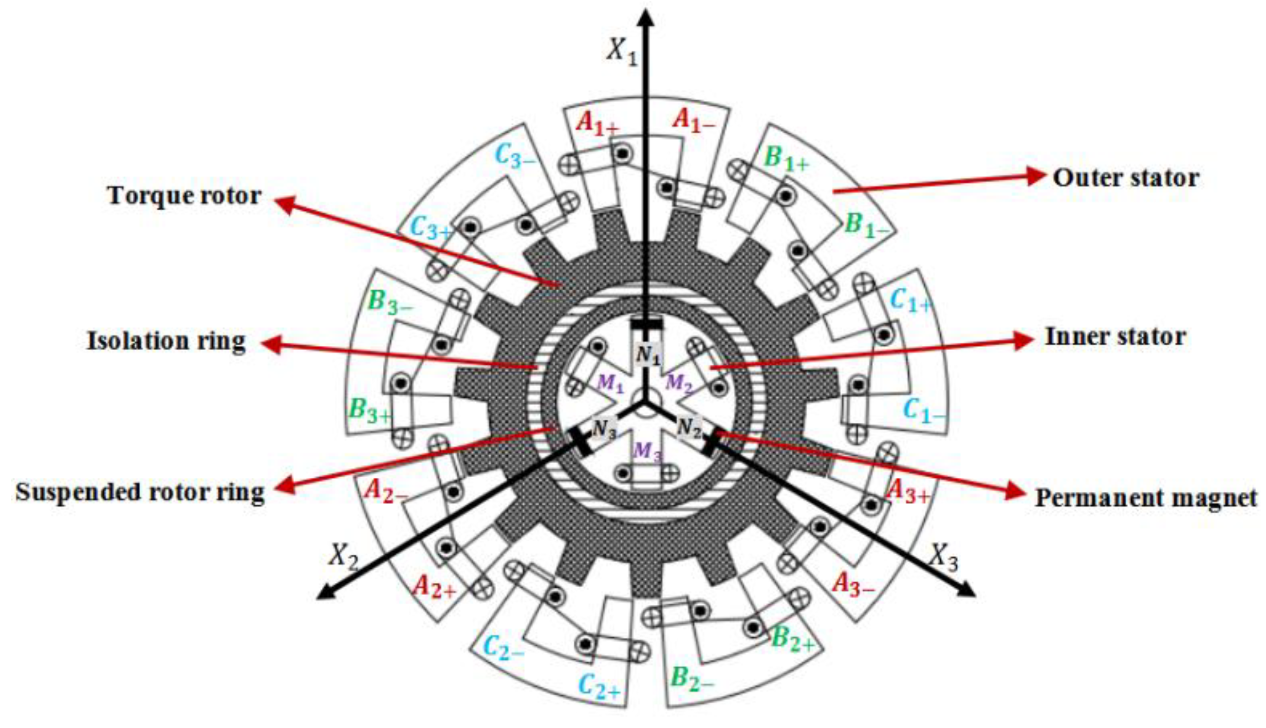
Figure 2.
A cosine-type torque distribution function diagram.
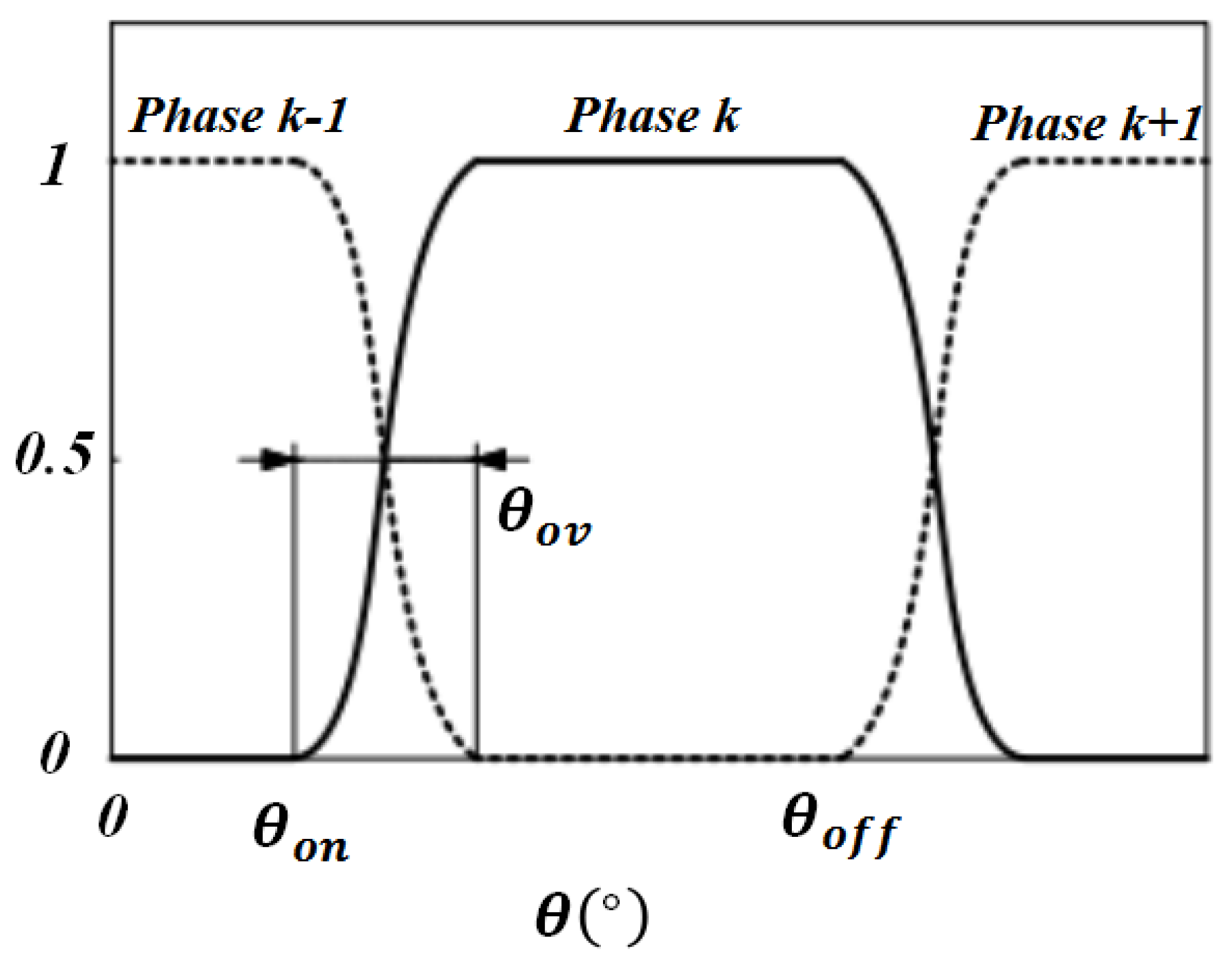
Figure 3.
PWM control signal. (a)The control signal of the switch tube in interval +. (b) The control signal of the switch tube in interval +.
Figure 3.
PWM control signal. (a)The control signal of the switch tube in interval +. (b) The control signal of the switch tube in interval +.
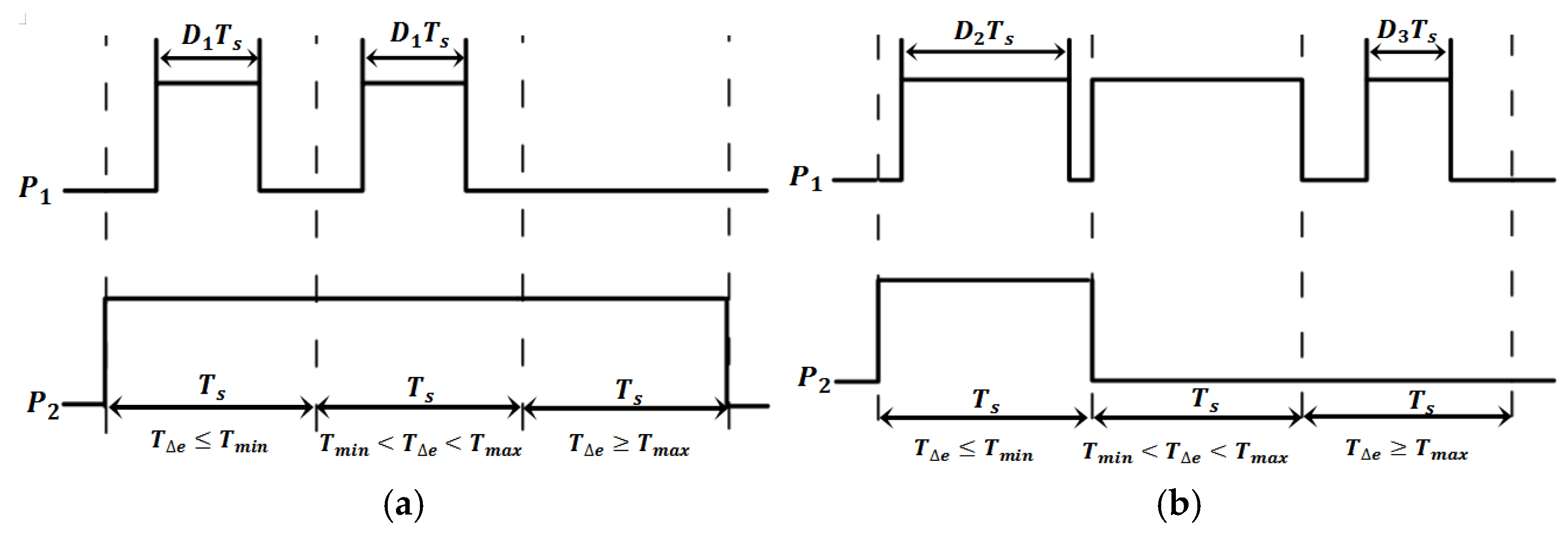
Figure 4.
Linear model inductance model.
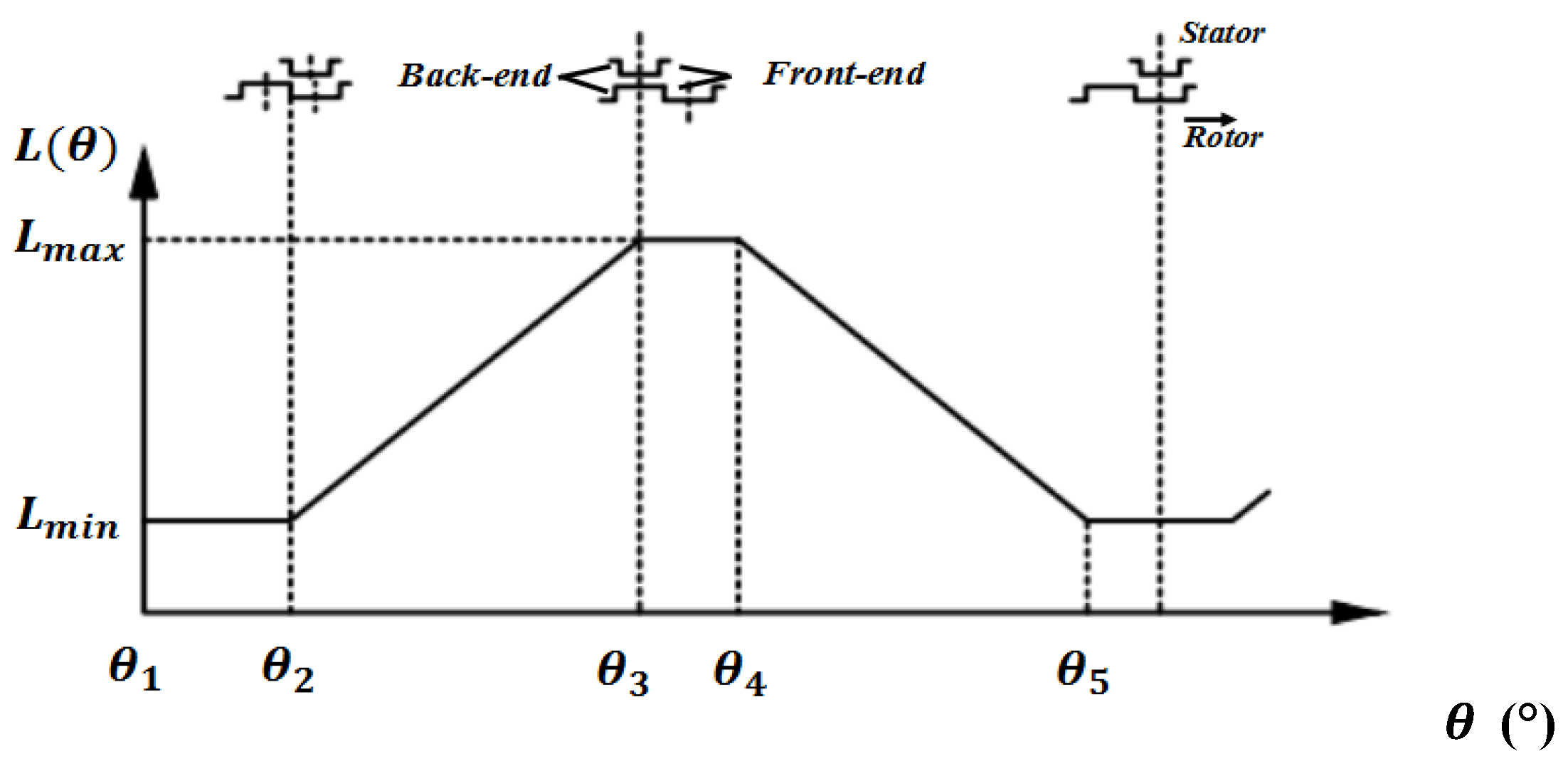
Figure 5.
Schematic diagram of the suspension force control.
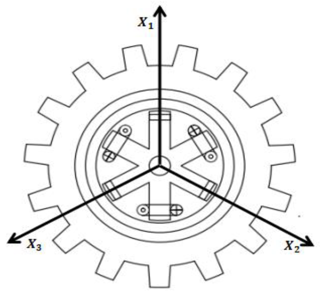
Figure 6.
Function curve of sgn(s) and sigmoid(s).
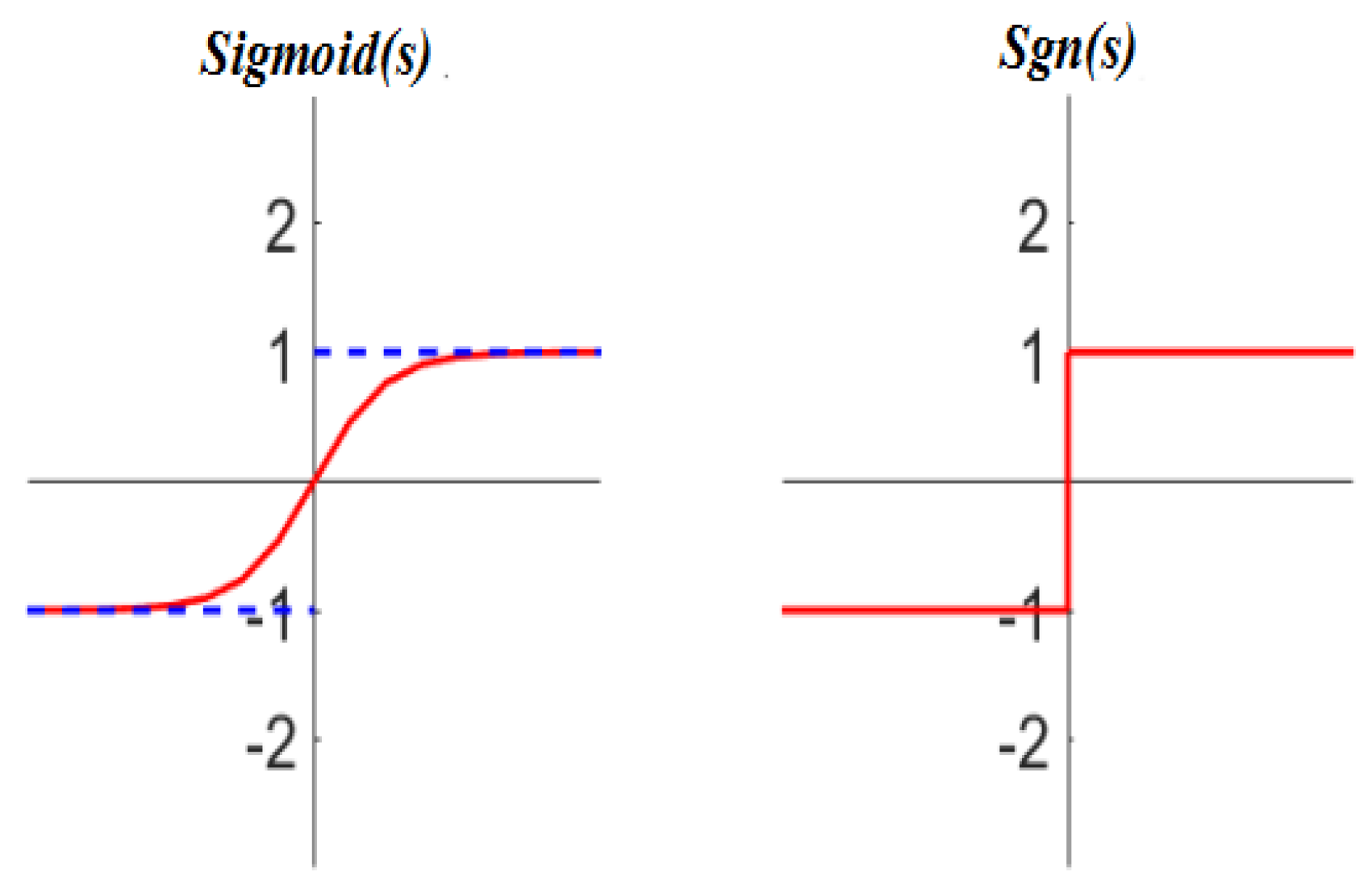
Figure 7.
Schematic diagram of the suspension force control.
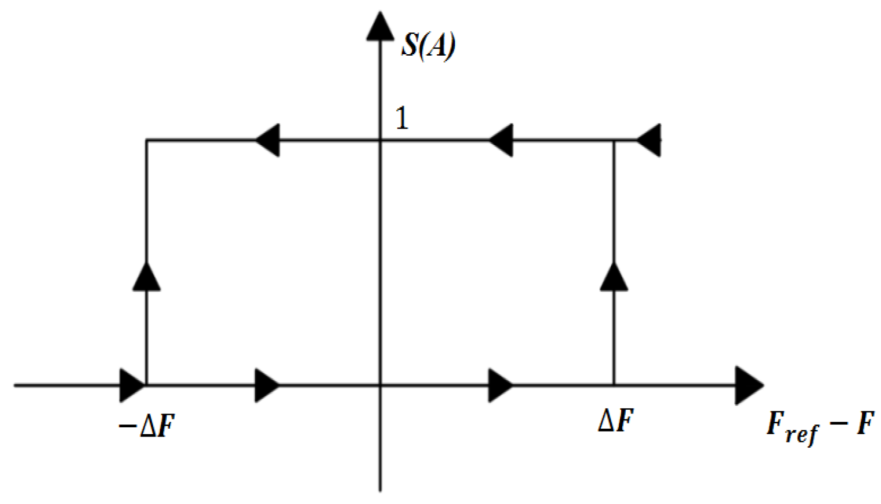
Figure 8.
TSMC schematic.
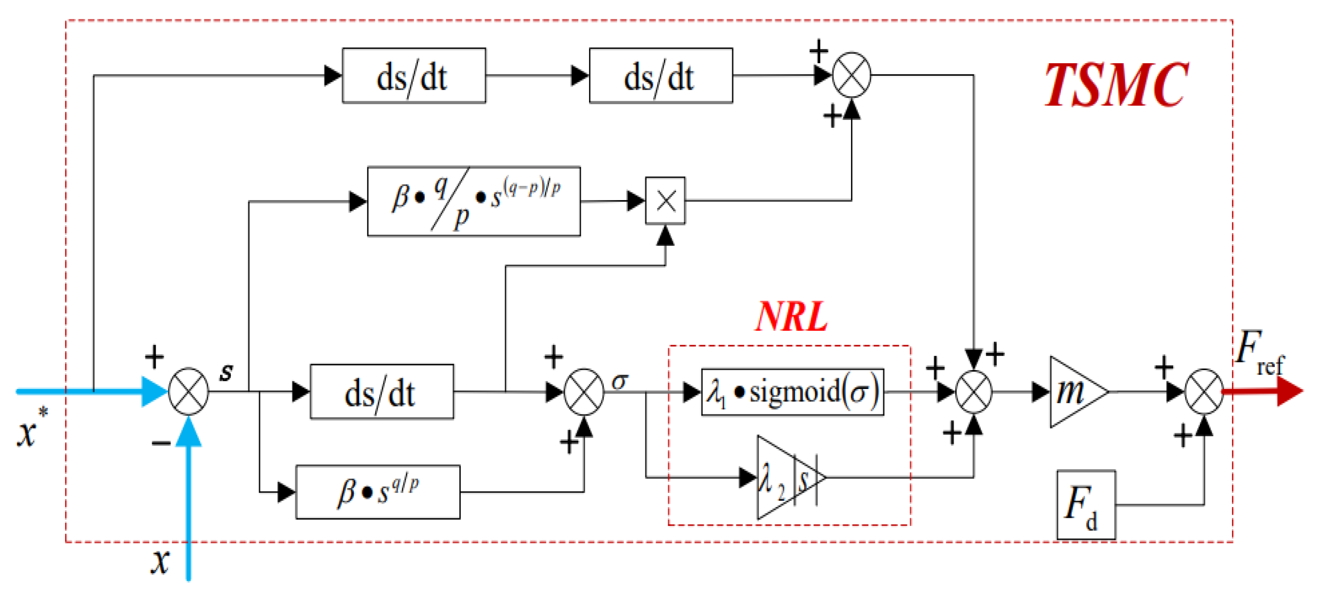
Figure 9.
DSBSRM control block diagram.
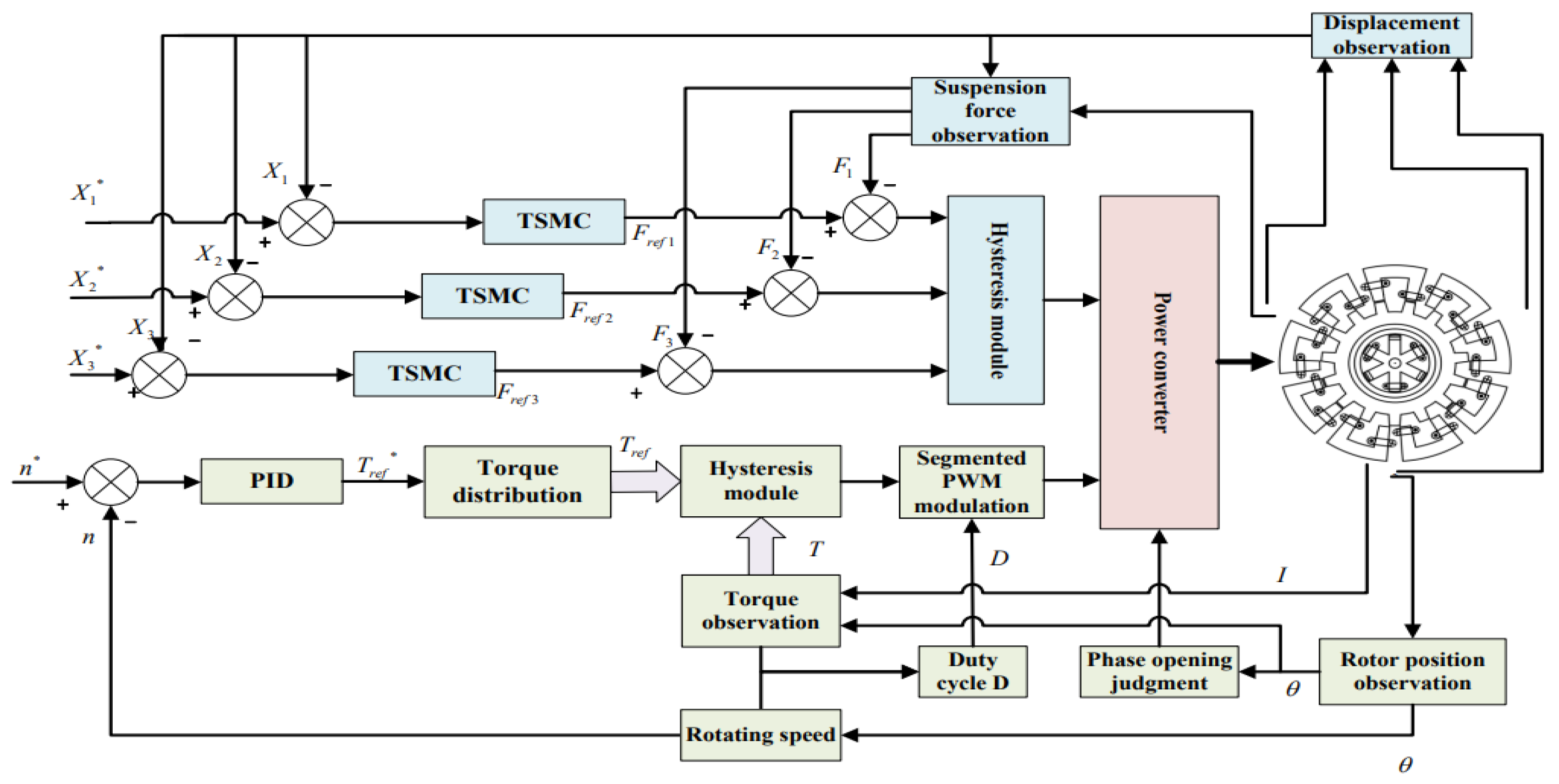
Figure 10.
Speed waveform comparison.
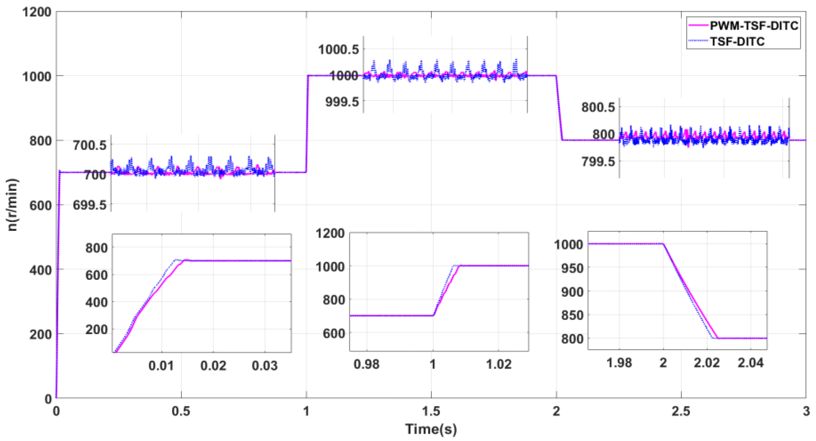
Figure 11.
Comparison of Torque Current Waveforms. (a) Improved TSF-PWM-DITC; (b) Traditional TSF-DITC.
Figure 11.
Comparison of Torque Current Waveforms. (a) Improved TSF-PWM-DITC; (b) Traditional TSF-DITC.
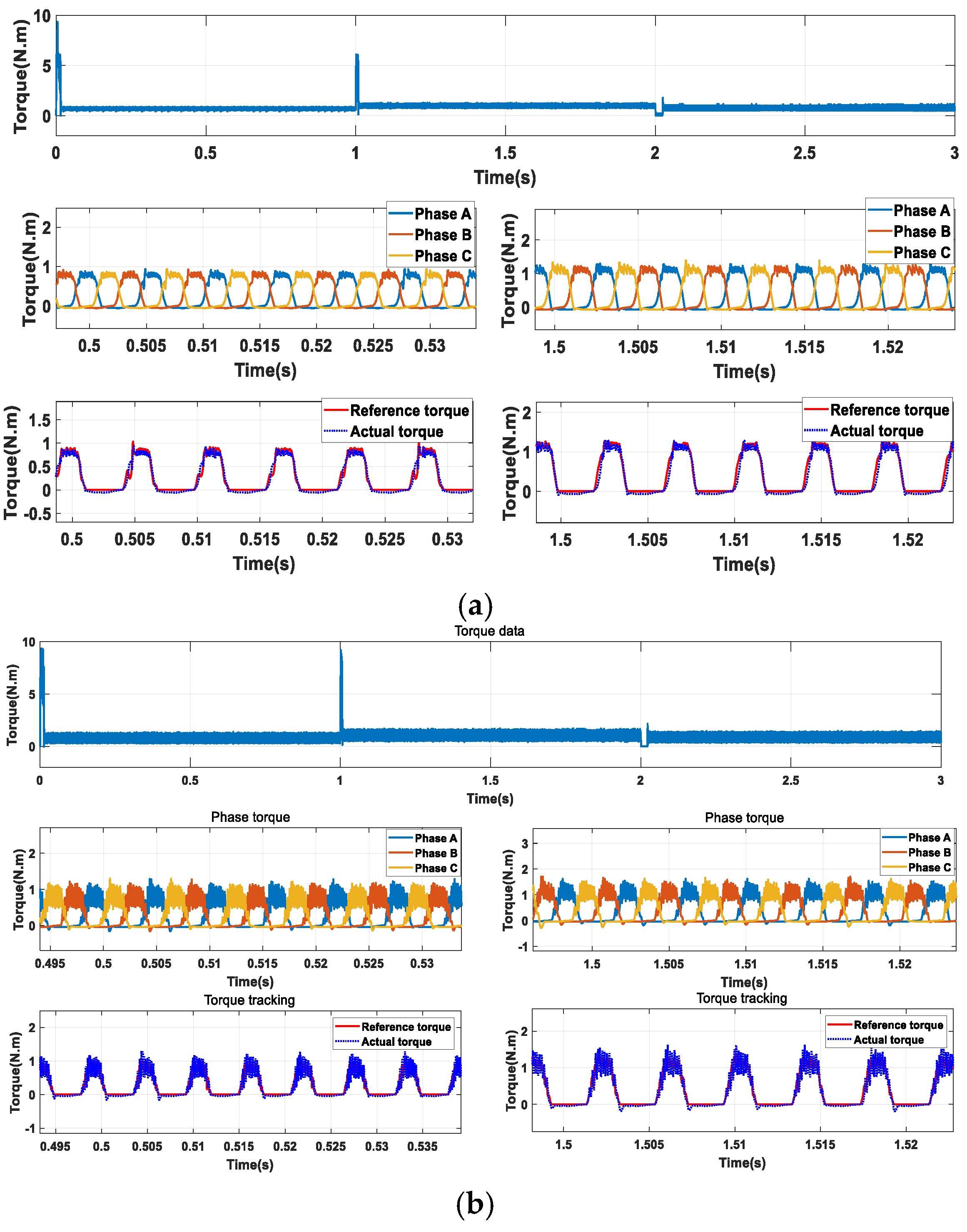
Figure 12.
direction displacement simulation waveform comparison.
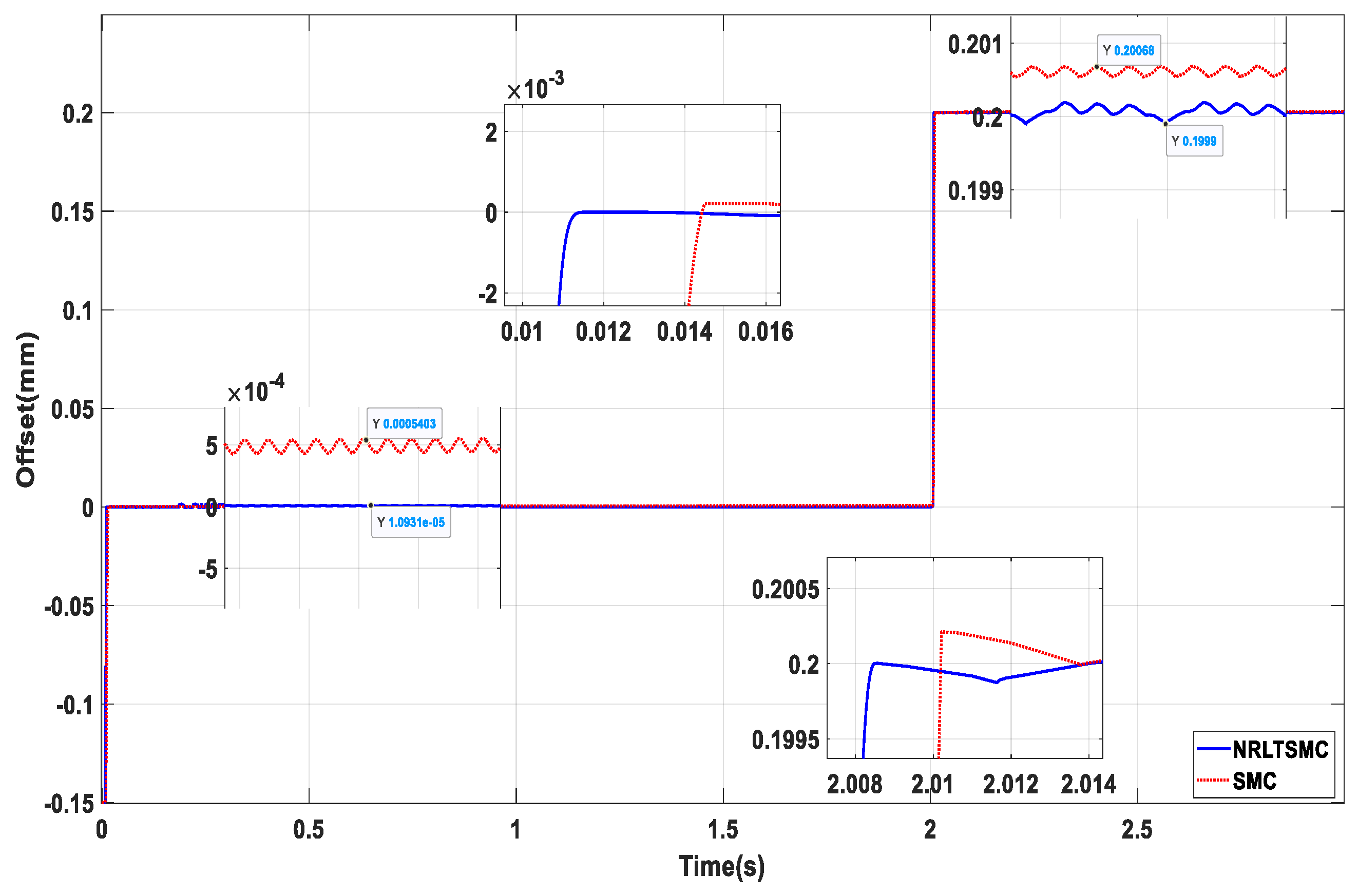
Figure 13.
direction displacement simulation waveform comparison.
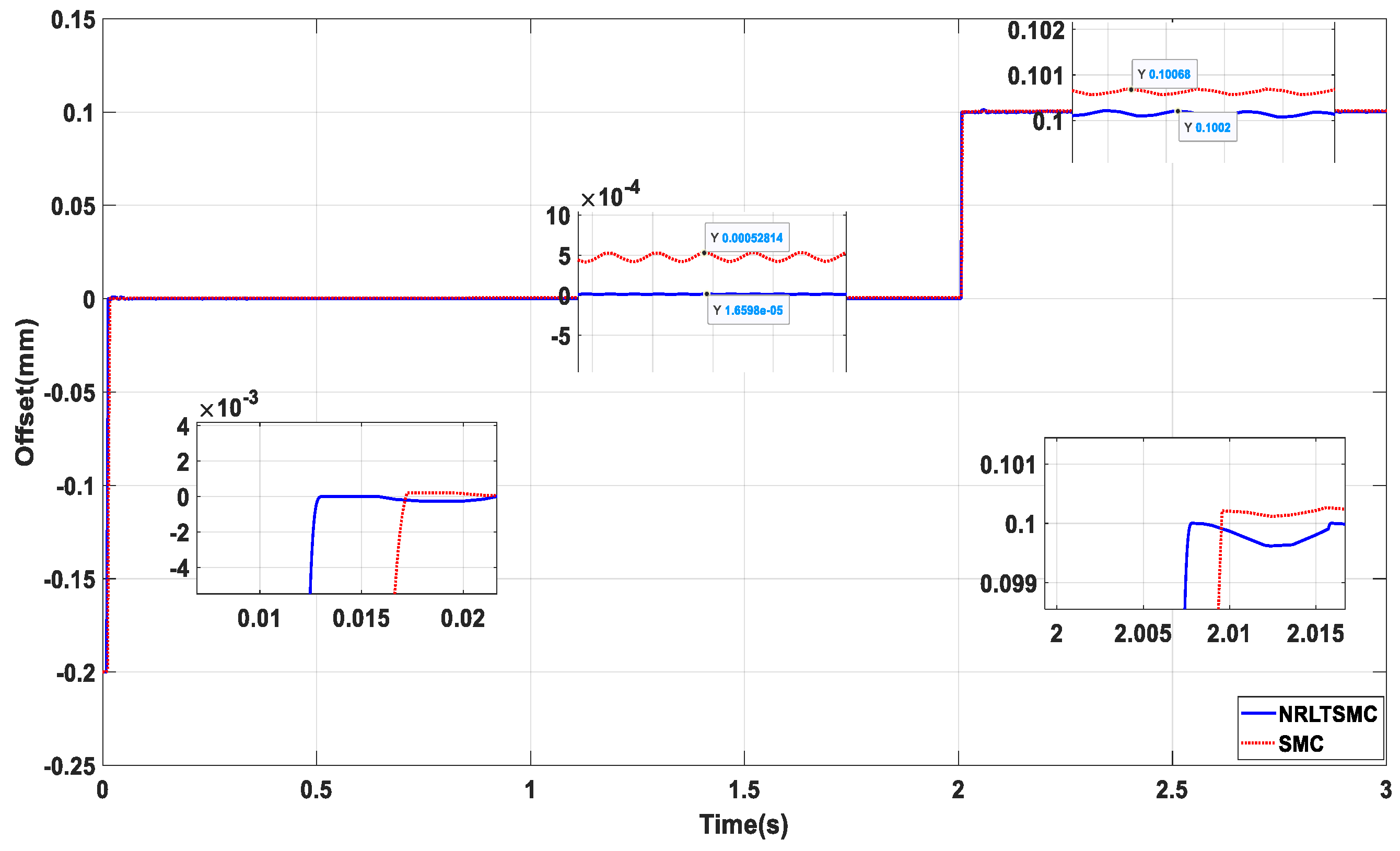

Table 1.
18/15/6-pole DSBSRM specific parameters.
| Parameters | 18/15/6-pole DSBSRM |
|---|---|
| The outer diameter of the outer stator | 80 mm |
| The internal diameter of the external stator | 52 mm |
| Rotor cooling diameter | 51 mm |
| The inner diameter of the rotor | 24 mm |
| Torque tooth height | 9 mm |
| Suspended tooth height | / |
| The outer diameter of the inner stator | 23 mm |
| The inner diameter of the inner stator | 4 mm |
| The thickness of the external stator yoke | 5 mm |
| The thickness of the inner stator yoke | 4 mm |
| Ring core thickness | 6 mm |
| Airgap thickness | 0.5 mm |
| The axial length of the motor | 100 mm |
| Torque tooth pole arc | 8° |
| External stator tooth pole arc | 8° |
| Internal stator tooth pole arc | 20° |
| Length of the magnetization direction of Permanent magnet | 1.5 mm |
| Torque winding turns | 100 |
Table 2.
Speed data analysis.
| Rated speed r/min | Index | Traditional TSF-DITC | Improvement of TSF-PWM-DITC |
|---|---|---|---|
| 700 r/min | Steady-state time (s) | 0.01243 | 0.01411 |
| Steady-state speed ripple (r/min) | 700.34~699.89 | 700.15~699.91 | |
| Maximum speed difference at steady state (r/min) | 0.45 | 0.24 | |
| 1000 r/min |
Steady-state time (s) | 1.0063 | 1.0083 |
| Steady-state speed ripple (r/min | 1000.33~999.77 | 1000.08~999.9 | |
| Maximum speed difference at steady State (r/min) | 0.56 | 0.18 | |
| 800 r/min |
Steady-state time (s) | 2.0225 | 2.025 |
| Steady-state speed ripple (r/min) | 800.2~799.7 | 800.09~799.87 | |
| Maximum speed difference at steady state (r/min) | 0.5 | 0.22 |
Disclaimer/Publisher’s Note: The statements, opinions and data contained in all publications are solely those of the individual author(s) and contributor(s) and not of MDPI and/or the editor(s). MDPI and/or the editor(s) disclaim responsibility for any injury to people or property resulting from any ideas, methods, instructions or products referred to in the content. |
© 2025 by the authors. Licensee MDPI, Basel, Switzerland. This article is an open access article distributed under the terms and conditions of the Creative Commons Attribution (CC BY) license (http://creativecommons.org/licenses/by/4.0/).
Copyright: This open access article is published under a Creative Commons CC BY 4.0 license, which permit the free download, distribution, and reuse, provided that the author and preprint are cited in any reuse.


