
Submitted:
05 August 2025
Posted:
07 August 2025
You are already at the latest version
Abstract
Electric Vehicles are gaining a lot of impetus due to their advantages over conventional vehicles. With the rise in demand for Electric Vehicles, there is also a rise in the demand for better and faster charging stations to provide seamless, easy and quick charging. The purpose of this paper is to talk about the electric vehicle charging stations and to briefly describe their operation. The paper also focuses on the various power quality issues and abnormalities developing in the grid, which may impact the operation of EV chargers, with a detailed discussion about Voltage Sags. The various causes of Voltage Sag are discussed, their effects on various converters are mentioned and the ways of overcoming Voltage Sags are derived. DVR, as a Voltage compensator, is used to overcome voltage sag. The graphs help to explain in better, the use of such devices for overcoming the issues.
Keywords:
EV
; PEV
; DVR
; DSTATCOM
; Voltage Sag
I. Introduction
The temperature across the surface of the earth has been rising steadily over the past couple of years due a myriad of incessant human needs and activities. This has called into action, to implement necessary reforms that will prevent this rise in global temperature. Two major things that could prevent this rise are:
- Clean Energy and its Utilization for all the purposes.
- Electric Vehicles and their Utilization.
Many market reports have suggested that, vehicles that acquire energy from the grid, called basically as the Plug-in Electric Vehicles, may account for up-to 20% of the automobile sales in the US [1,2]. Thus, we can reasonably assume that a large number of houses will have a PEV, which in a lot of cases, will charge from the residential distribution feeders. Vehicle charging rates vary over a wide range, with SAE Standard J1772[3] define Level1 charge rates up-to 1.9kW, and Level2 up to 19.8 kW. It is anticipated that charging rates of around 5 kW will be quite common [4]. Putting into context, average household electricity consumption is around 1.3kW [5]. It is likely that financial incentives will encourage charging overnight, when background non-PEV demand is less than average [6]. Thus, during overnight hours, PEV load would contribute a significant load demand. A demand with large numbers of similar devices, can synchronize their response and collectively result in destabilizing the grid. It is shown in this paper that if the penetration of PEV-charging load is sufficiently high, voltage sag on distribution feeders. The response of PEV chargers to power-quality events is governed by SAE Standard J2894 [7], which updates an earlier report from the Electric Power Research Institute (EPRI) [8]. As with FIDVR, the response of PEV chargers to low-voltage events is of particular interest.
Two cases are covered in SAE J2894:
- 1)
- Voltage sag: PEV chargers must remain energized if the supply voltage drops to 80% of nominal for up to 2s.
- 2)
- Momentary outage: PEV chargers must ride through a complete loss of voltage for up to 12 cycles.
Situations where voltages sag below 80%, but remain non-zero, are not explicitly covered by the standard. [9]
The topic of Power Quality has gained a lot of impetus due to its effects on sensitive controllers in industries and on various devices in the Power Grid. Some amount of Voltage Sag, along with its effects, could lead to complete destruction of the controllers and would lead to a huge loss. For example, Grid Voltage Sags, which propagate into the EV chargers working in Grid to Vehicle mode or Vehicle to Grid mode, may result in having huge impacts on the Electric Vehicles, thereby reducing their battery life [10]. With a large voltage sag, the load gets disconnected from the grid. This, on restoration, could lead to larger voltage rise. This voltage rise, may further result into disconnection or tripping of other equipment connected to the feeder. Thus, the impact of Power Quality issues, especially the likes of Harmonics and Voltage Sags, cannot and should not be ignored.
This paper focuses upon the Power Quality issue of Voltage Sag, explaining about the formation of voltage sag in a 230V Single Phase System, which has multiple loads, precisely Electric Vehicle Loads connected to it. The paper then talks about the effects of Voltage Sag on various converters and devices in the System, thereby listing methods to curb the problem of Voltage Sag.
II. The Electric Vehicle Charging Station Model
Figure 1 shows different schematics of an EV Charging Station:
Figure 1 is a bi-directional three phase EV charging system, whose parameters can be referred to [20].
Figure 2 shows the average model of EV Charging station.
Various charging modes for Electric Vehicle Chargers are mentioned in the Table 1. It can be referred to [19].
The most important components that are present in an EV charging station are as follows:
- 1.)
- Bi-directional AC-DC Converter: A bi-directional AC-DC Converter helps in conversion of the AC voltage in the grid to DC, in order to provide the necessary DC voltage required for Charging the batteries.
Advantage of using a Bi-directional AC-DC converter is that it can be utilized in a system where a Vehicle to Grid technology has to be adopted.
- 2.)
- Bi-directional DC-DC Converter:
The main purpose of a bi-directional DC-DC converter is that, it converts the input DC voltage to the required DC voltage. Mostly, used as a Boost converter.
The most recent DC-DC Converters are bi-directional, as they have the characteristics which can be utilized for Vehicle to Grid technology.
III. Power Quality Issues in an EV Charging Station
This section talks about the various Power Quality issues which may occur during the charging process or on the transmission line. They are as follows:
- 1)
- Harmonics
- 2)
- Total Harmonic Distortion
- 3)
- Voltage Fluctuations or Flicker
- 4)
- Voltage Sags/Swells
In this paper, we discuss the effects of Voltage Sags.
IV. Voltage Sag
Voltage sags are considered to be one of the most harmful power quality problems, due to their effect on the proper operation of several types of end-user equipment. This short- duration reduction in RMS voltage are caused due to load variations, power system faults and more many. [11].
The most common cause of voltage sags is the flow of fault current through the power system impedance to the fault location. Hence, power system faults in transmission or distribution can affect respectively a large or small number of customers. A fault in a transmission line affects sensitive equipment up to hundreds of kilometers away from the fault [12]. In both, transmission and distribution, voltage sags due to faults in parallel feeders, produce incorrect operation of industrial customer equipment [13].
Magnitude, duration, phase-angle jump and the shape, define voltage sags. Power System performance during the event occurrence are considered. For Power System performance research, real data is difficult to be available. Thus, simulation tools are used.
A. Definitions:
Various definitions of voltage sag and its main characteristics are referred from [14] and presented here:
- Voltage sag: Reduction in RMS voltage between 0.1 to 0.9 pu or current at the power frequency for durations of 0.5 cycle to 1 min [15].
- Magnitude: The lowest RMS value of the voltage during a voltage sag [11].
- Duration: The time during which the RMS value of voltage is under the threshold (0.9 pu) [11].
- Phase-angle jump: The difference between the phase angle of the voltage during an event and the phase angle of the voltage before the event [11].
- Shape: It defines the behavior of the RMS voltage profile during voltage sags. According to their shape, voltage sags are classified to be rectangular (RMS voltage value is constant) or non-rectangular (RMS voltage value varies) [16].
- Point-on-wave of sag initiation: The phase-angle of the fundamental voltage wave at the instant of sag initiation [11].
- Pre-fault voltage: Voltage value during an interval ending with the inception of a fault [11].
B. Voltage Sag Characterization:
The above voltage sag definitions and characteristics have been referred to [14] can be characterized as follows:
Consider Figure 3
The above Figure 3, consists of the various characteristics of Voltage Sag. It usually consists of defining and quantifying the parameters of this disturbance such as Magnitude, Duration, Phase angle jump and shape.
The sag duration depends mainly on the fault clearing time provided by electrical protection, which can be determined by simulating the electrical protection behavior, when dealing with system faults.
Magnitude and the phase angle jump depend upon the fault location and the line impedance. They can be determined at different nodes by simulating system faults.
C. Theoretical Calculation of Voltage Sag
The Figure 6, below, shows a basic model in order to calculate the voltage sag, during a 3-phase fault on a basic radial system.
The voltage at the point of common coupling can be calculated as in Equation (1):
Where,
Vsag: It is the voltage sag
Zf : It is the Feeder impedance
Zs : It is the source impedance
V. Various Effects of Voltage Sags
Voltage sag has tremendous effects on transmission systems. If not controlled in due time, it may lead to hazardous consequences. Today’s modern industrial applications consist of various very sensitive devices, which are prone to being damaged at the slightest of changes in quality of power.
Nonetheless, this issue of Voltage Sag is given a lot of importance in the power industry.
A. Impact of Voltage Sag of Different Types of Converters:
Reference [17] talks about various types of chargers which are or can be used in the Electric Vehicle Charging Station. It also discusses the effects Voltage Sags could have on the performance of these chargers.
The various types of Voltage Sags are Single Phase, Two Phase Voltage Sags and Three Phase Voltage Sags as discussed about in [18]. Voltage Sags can also be of 7 different types when phase jumps are considered. EV chargers adopt three-phase power supply, so separately analyzing the impacts of single- phase, two-phase and three-phase voltage sags on EV chargers would be helpful. Three types of Converter Chargers are considered for this study.
- Six Pulse Rectifier Charger
- Twelve Pulse Rectifier Charger
- PWM Rectifier Charger
The parameters for the above chargers can be referred to in [17] and the effects of Voltage Sag are studied in these as follows:
- 1)
- Single Phase Voltage Sags [17]:
The reference talks about the effects of Single voltage sag as a phenomenon caused mainly due to short circuit faults in electric power system which in single phases, accompanies a phase jump.
From the above figures and from the reference, it can be seen that, single phase Voltage Sags have relatively less impact on 3 phase chargers.
- 2)
- Two Phase Voltage Sags:
Reference [17] talks about the impact of Two Phase Voltage Sags on the above-mentioned Converter Chargers.
As is shown in Figure 10, the output voltage of the 6-pulse charger is approximately in positive proportion with the phase jump.
The output voltage of 12-pulse rectifier charger has almost no change when phase jump value is less than 80°. The output voltage begins to drop rapidly until the phase jump value is greater than 80° [17].
The PWM rectifier charger has no change in its output voltage when phase jump value is less than 90°.When phase jump value is 95°, the output voltage waveform is shown in Figure 9 [17].
Figure 11 shows that, the PWM rectifier charger still can’t work properly after the sag was eliminated. A big phase value jump has more impact on chargers. Phase jump whose value is less than 90°, causes a big impact on 6-pulse rectifier charger, while there are almost no effects on 12-pulse rectifier charger and PWM rectifier charger [17].
So, it can be considered that the phase jump has no effect on 12-pulse rectifier charger and PWM rectifier charger.
- 3)
- Three Phase Voltage Sags:
When the three-phase voltage sag magnitude reaches 0.7 p.u., normal functioning of the 6-pulse rectifier charger is affected. The output voltage of a 6-pulse rectifier charger and a 12-pulse rectifier charger are approximately in positive proportion with the input voltage, while the output voltage of PWM rectifier drops rapidly when the input voltage falls below a certain value [17].
There is a minimum critical voltage sag during which EV chargers can keep stable and recover after the sag, and the charger system collapsed immediately when the voltage sag which is less than the minimum-allowed voltage sag occurred and could not return to the original state after the sag was eliminated [17].
Consider the Figure 12,
Voltage Sag duration is also an important factor, which influences the normal operation of chargers. The results state that, EV chargers can remain stable when sag duration is 0.2 sec. While, they can’t return to their original state after the original sag was eliminated when sag duration is 0.5 sec [17].
The output power of the charger is another important factor that can influence the ability of charger to cope with the voltage sag. Figure 12 shows that, the charger can’t work normally under rated output power when the sag duration is 0.5s. But, the charger would work normally if the output power was reduced to half of the rated power. Therefore, the smaller the output power of chargers, the stronger is the ability to cope with the voltage sag [17].
B. Over-Voltages Due to Synchronous Tripping of EV Plug-In Chargers Following Voltage Dips
Authors in [9] have identified a potentially significant issue associated with large-scale PEV charging. When grid voltages sag below 80% of nominal, PEV chargers are likely to trip [7]. Voltage sags may often affect the entire distribution feeders, and may even be more widespread. It is therefore quite believable that voltage-sag events may affect large numbers of PEVs, leading to synchronous response and a consequent drop in load. Putting this into context, most PEV charging will occur at night, when non-PEV load is at a minimum. Voltage-sag induced tripping of PEV-charging loads could result in the loss of a significant proportion of the total load. [9]
When the initiating event is cleared, voltages will instantly rise above their pre-disturbance levels due to the reduction in load. Post disturbance voltages may easily exceed 1.1 p.u. This would result in further load tripping, including many of the remaining PEV chargers [7]. This resulting overvoltage could damage electrical equipment and the remaining loads [9].
Figure 13.
Response of voltage to a 300msec voltage sag on a node of a primary feeder [9].
Figure 13.
Response of voltage to a 300msec voltage sag on a node of a primary feeder [9].
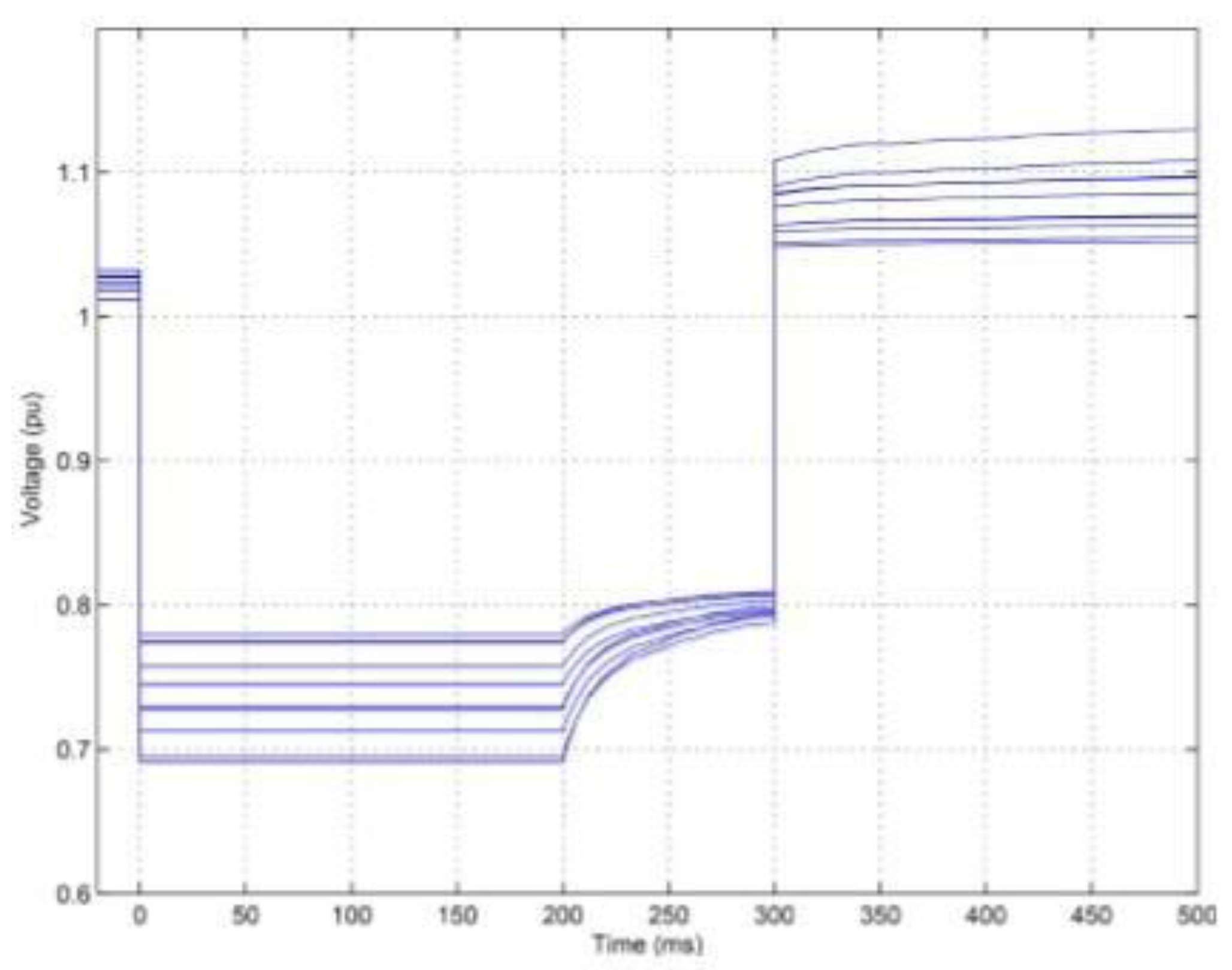
According to [9],
A node was subjected to a voltage drop from 1.0 to 0.8 p.u., for a period of 300msec.Voltages at all nodes are shown in Figure 11, while Figure 14 showed the number of PEV chargers that remained connected at each node [9].
PEVs are prevented from tripping during the first 200msec, but may trip after that time period. As PEV chargers trip, voltages rise slightly, so the rate of tripping subsides. Nevertheless, on restoring the system voltage to 1.0 p.u. at 300 ms, voltages at some nodes exceed 1.1 p.u. PEV tripping then continues at those nodes due to the excessively high voltages [9].
Figure 15 is an analysis of overvoltage in a 3-phase network model. talks about the post disturbance phase voltage. From the figure, it can be seen that as the voltage sag happens for a particular duration, there happens to be tripping. When the voltage is restored and there is 100% loading, a 20% drop in the load would result in node voltage reaching 1.1 p.u. This load drop is applied across all the loads. Figure 15 shows the three phase voltages along the main feeder when there is a drop of 20% [9].
The usual methods to control distribution feeder voltages, are too slow to prevent over-voltages when the initiating event is cleared. The load-loss problem is a consequence of the low- voltage characteristics of PEV chargers, which are determined by the governing standard [7]. Altering these standards to ensure grid-friendly low-voltage-ride-through would eliminate the wide-spread PEV load tripping. The over-voltages would become a nonissue [9].
Reference [9] shows that PEV load tripping could result in excessive voltage imbalance and could result in individual phase voltages rising to unacceptable levels.
VI. Schematic & Results
To explain the phenomenon of Voltage Sag, a simulation model was designed of an Electric Vehicle Charging Station. Figure 16 is a schematic for it. The parameters are as follows:
- Input Voltage: 240V AC
- Frequency: 60Hz
- An AC-DC Bidirectional Rectifier which converts the AC to DC approximately to a low value.
- This DC Value is converted to the required DC Voltage level using a Bi-directional DC-DC Converter.
- The Type of charger that is being designed is a Level 2 Charger. The charger has an output around 240V to charge the vehicles.
- A DVR circuit to compensate for the Voltage Sag.
The problem of Voltage Sag can have tremendous harmful effects on the performance of different types of equipment and loads which are connected in the Electric Power System. These effects have been discussed briefly in the section V. This section talks about the measures which can be incorporated to mitigate Voltage Sag.
There are various devices which can be utilized in order to overcome the problem of Voltage Sag. Some of these devices are as follows:
- 1)
- DSTATCOM: It can operate in two modes.
- a)
- Current Control : DSTATCOM in this mode acts as an active filter, power factor corrector, load balancer.
- b)
- Voltage Control : DSTATCOM here can regulate a bus voltage against any distortion, sag or swell or against unbalance or short duration interrupts.
- 2)
- DVR: It is a series compensated device which is used to protect a sensitive load from sags or swells. Voltage at the load terminal can also be regulated.
A system is designed considering Cost in mind and to overcome the problem of Voltage Sag or Swell. Thus, in this paper, a DVR is used to over-come the problem of Voltage Sag.
There are multiple reasons of Voltage Sags. One of the reasons being withdrawal of high current than expected or rated. Considering the example of an Electric Vehicle Charging Station a Voltage Sag is possible, which could be possible due to a large load which draws a very high current. To overcome this, a DVR can be utilized.
DVR is a series compensated device which injects a voltage component in series with the supply voltage to compensate the voltage sags and swells. A control response in the order of 3msec to ensure a secure voltage supply under transient conditions. The various components that make up the DVR system are Filter Circuit, a PWM inverter and a Storage Unit.
The schematic mentioned in Section VI has a DVR circuit connected in-order to compensate for the Sag.
The above three waveforms display the conditions of voltage sag.
Voltage sag is a phenomenon which occurs due to a large number of reasons. One of these being, large amount of current which is drawn from the circuit or from the grid in this case by a load. This large withdrawal of current leads to voltage sag generation across the sensitive load. A grid connected EV Charging Station interconnected with multiple loads like residential loads would lead to a voltage sag affecting the residential loads when such high amount of current is drawn by any Electric Vehicle. Similarly, Figure 17(a) talks about a Voltage Sag being generated after no disturbance for some amount of time. In Figure 17(a) a Voltage Sag across the grid, is caused at t=0.1 sec. It has been simulated as a fault condition being caused at that particular time due a load, which draws a high amount of current. Voltage sags by up-to 50%, which affects the sensitive loads. This voltage is later compensated by the use of a DVR circuit.
Figure 17(b) is the waveform for voltage across the capacitor. When a Voltage Sag occurs at t=0.1 sec, this Voltage Sag is compensated by the DVR circuit. The sag in the bus voltage is detected and with the help of the capacitor and the available energy storage backup or a battery backup, this Voltage Sag is compensated for. The grid voltage is continuously monitored for a sag. To do this, the grid voltage is compared with the reference voltage. If the Grid Voltage falls below a threshold value, Voltage Sag compensation takes place with the help of the control system designed for the DVR.
Finally, Figure 17(c), shows the Voltage that is supplied to the load. The compensation through the DVR makes sure that the voltage across the load remains constant, even across the most sensitive loads. Thus, in this way, a proper sinusoidal voltage reaches the load. In this way, the entire operation functions. It is therefore possible to protect other sensitive loads like a residential load in case this is a system inter-connected with the grid.
VII. Conclusion
To conclude, in this paper, we tried to discuss briefly the Electric Vehicle charging station. Its general schematic and average models helped in understanding it deeper. The various power quality issues were mentioned, and the power quality issue of Voltage Sag was discussed in detail. We talked about the various causes of Power Quality issues which are possible in an Electric Vehicle Charging Station. The paper also discussed in brief, the effects this issue of Voltage Sag could have on various converters and also the after effects of Voltage Sag. Finally, the results of a simulation model performed, were shown and the use of a DVR as a compensation device was shown. The process of voltage sag compensation was explained via graphical representation and it’s the voltage sag compensation for the simulation was achieved. Its results are shown.
VIII. Future Scope
- Solution to prevent immediate voltage rise after a sag is also extremely important.
- Using a UPQC. UPQC has the characteristics of a DSTATCOM and a DVR. It can well perform the functions of both. It can correct current and voltage both whereas others can correct them individually.
- Using Electric Vehicles connected to Grid as the energy storage device in place of or along with other batteries for voltage compensation in case of faults caused.
- Revising the standards to incorporate & overcome the after effects of a voltage sag could be a savior.
References
- M. Book, X. M. Book, X. Mosquet, G. Sticher, M. Groll, and D. Rizoulis, “The comeback of the electric car? How real, how soon, and what must happen next,” Boston Consulting Group, Boston, MA, USA, Focus Rep., Jan. 2009.
- R. Lache, D. R. Lache, D. Galves, and P. Nolan, “Electric cars: Plugged,” Global Autos Research Team Deutsche Bank, Jun. 2008.
- Sheth, K. , Patel, D., & Swami, G. Strategic insights into vehicles fuel consumption patterns: Innovative approaches for predictive modeling and efficiency forecasting. International Journal of Engineering Research & Technology (IJERT) 2024, 13, 1–10. [Google Scholar]
- C.Fietzek,”Electric vehicle and charging: Charging strategy and communication,” presented at the Elect. Power Res. Iinst. Infrastructure Working Council, Tempe, AZ, USA, Dec. 2010.
- U.S. Energy Inf. Admin., “2010 electric sales, revenue, and average price: Table 5.a,” Washington, DC, USA, Nov. 2011.
- SAE International,”Power quality requirements for plug-in electric vehicle chargers,” Surface Vehicle Recommended Practice J2894–1. Warrendale, PA, USA, Dec. 2011.
- Sheth, K. , & Patel, D. Comprehensive examination of solar panel design: A focus on thermal dynamics. Sustainable Green Energy Research & Engineering 2024, 15, 23–35. [Google Scholar] [CrossRef]
- Elect. Power Res. Inst., “EV charging equipment operational recommendations for power quality,” Palo Alto, CA, USA, Final Rep. TR-109023, Nov. 1997.
- Swami, G. , Sheth, K., & Patel, D. From ground to grid: The environmental footprint of minerals in renewable energy supply chains. Current World Environment and Energy Economics 2025, 14, 141002. [Google Scholar] [CrossRef]
- M. Bollen, Understanding Power Quality Problems: Voltage Sags and Interruptions. IEEE Press on Power Engineering, 2000, pp. 139-251.
- Swami, G. , Sheth, K., & Patel, D. PV capacity evaluation using ASTM E2848: Techniques for accuracy and reliability in bifacial systems. Sustainable Green Energy Research & Engineering 2024, 15, 159012. [Google Scholar] [CrossRef]
- IEEE Standards Coordinating Committee 22 on Power Quality. IEEE Std 1346. IEEE Recommended Practice for Evaluating Electric Power System Compatibility With Electronic Process Equipment. 1998.
- R. Dugan, Electrical Power Syatems Quality, 2nd ed. McGraw-Hill, 2004, pp.43–110.
- J. Caicedo, F. J. Caicedo, F. Navarro, E. Rivas and F. Santamaría, “Voltage sag characterization with Matlab/Simulink,” 2012 Workshop on Engineering Applications, Bogota, 2012, pp. 1-6.
- IEEE Standards Coordinating Committee 22 on Power Quality. IEEE Std 1159. IEEE Recommended Practice for monitoring electric power quality. 1995.
- CIGRE/CIRED/UIE Joint Working Group C4. 110. Voltage Dip Immunity of Equipment and Installations. 2010.
- Sheth, K. , & Patel, D. Strategic placement of charging stations for enhanced electric vehicle adoption in San Diego, California. Journal of Transportation Technologies 2024, 14, 64–81. [Google Scholar] [CrossRef]
- Sheth, K. , Patel, D., & Swami, G. Reducing electrical consumption in stationary long-haul trucks. Open Journal of Energy Efficiency 2024, 13, 88–99. [Google Scholar] [CrossRef]
- Sheth, K. , & Patel, D. Comprehensive examination of solar panel design: A focus on thermal dynamics. Sustainable Green Energy Research & Engineering 2024, 15, 151002. [Google Scholar] [CrossRef]
- Arancibia, K. Strunz, and F.Mancilla-David. A unified single-and three-phase control for grid connected electrical vehicles. IEEE Trans. Smart Grid, 2013; 1780–1790. [Google Scholar]
Figure 1.
Schematic Circuit of an EV Charging Station [20].
Figure 1.
Schematic Circuit of an EV Charging Station [20].
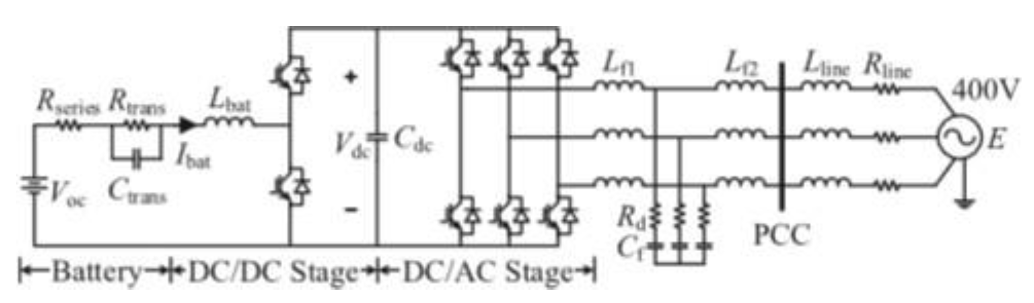
Figure 2.
Average Model of EV Charging Station [20].
Figure 2.
Average Model of EV Charging Station [20].
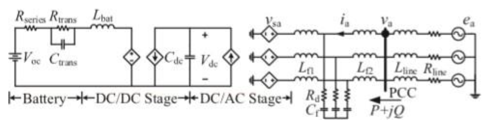
Figure 3.
Characteristics of Voltage Sag [14].
Figure 3.
Characteristics of Voltage Sag [14].
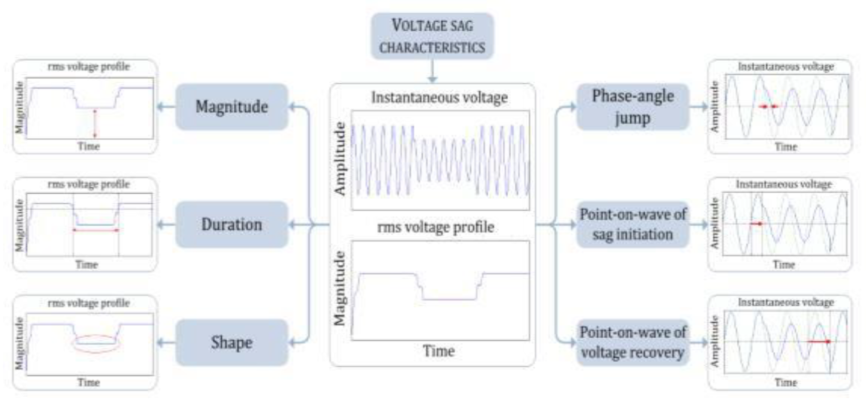
Figure 4.
Instantaneous Voltage [14].
Figure 4.
Instantaneous Voltage [14].
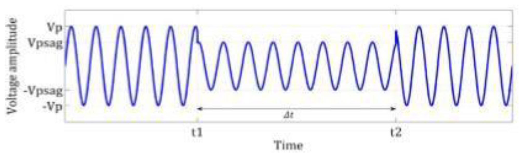
Figure 5.
Voltage Magnitude [14].
Figure 5.
Voltage Magnitude [14].
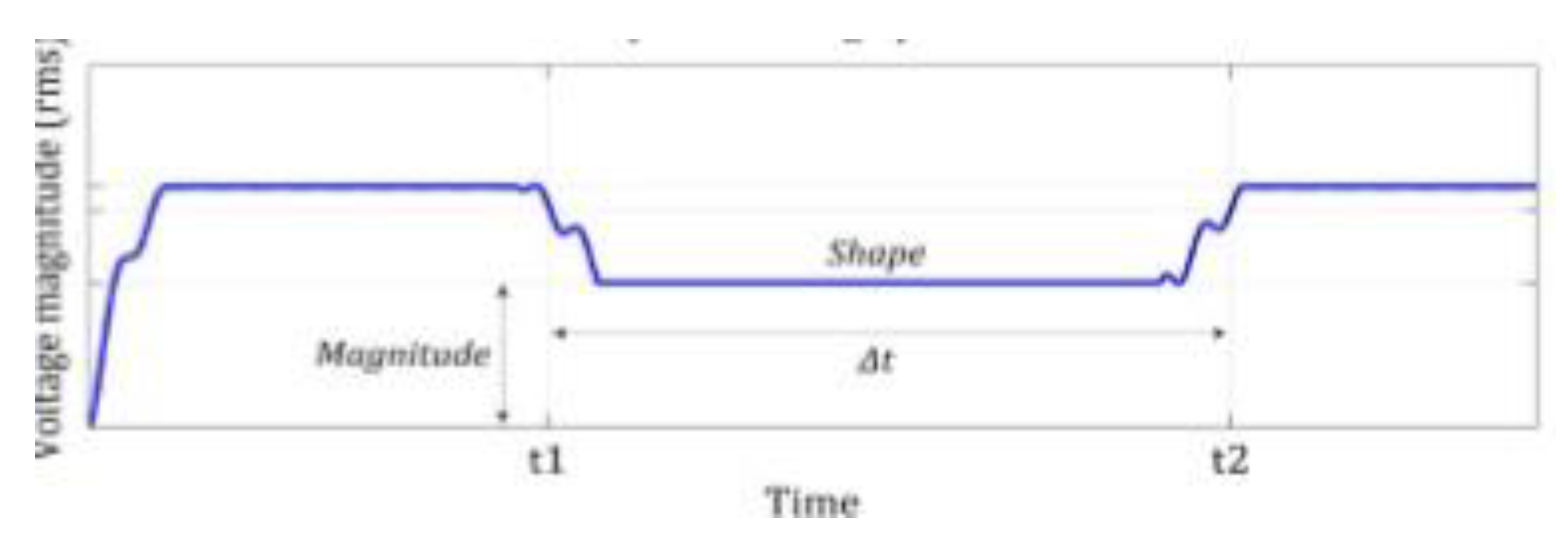
Figure 6.
Voltage divider mode for Voltage Sag calculation [14].
Figure 6.
Voltage divider mode for Voltage Sag calculation [14].
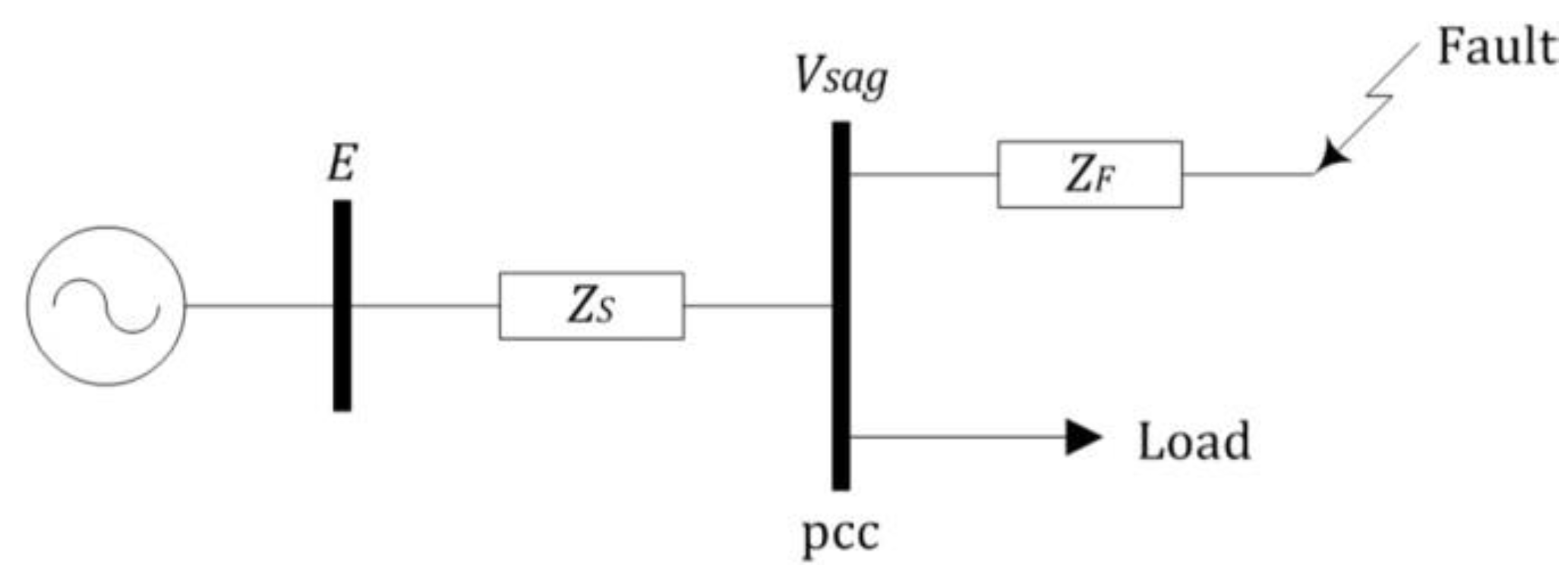
Figure 7.
DC-DC Input Voltage Waveform for a 6-pulse charger [17].
Figure 7.
DC-DC Input Voltage Waveform for a 6-pulse charger [17].
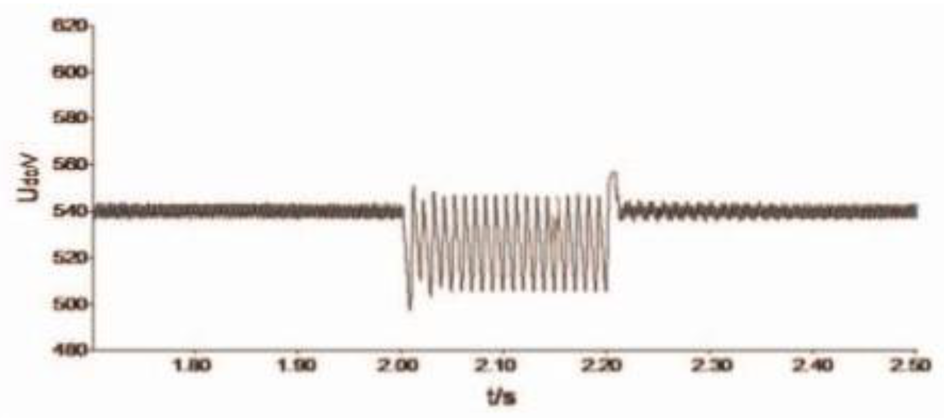
Figure 8.
DC-DC Input Voltage Waveform for a 12-pulse charger [17].
Figure 8.
DC-DC Input Voltage Waveform for a 12-pulse charger [17].
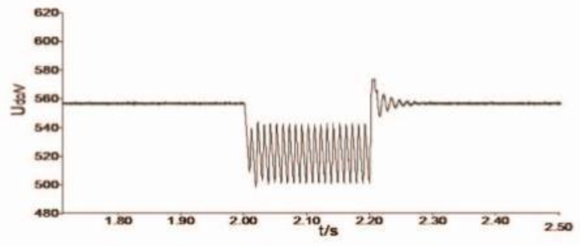
Figure 9.
DC-DC Input Voltage Waveform for a PWM charger [17].
Figure 9.
DC-DC Input Voltage Waveform for a PWM charger [17].
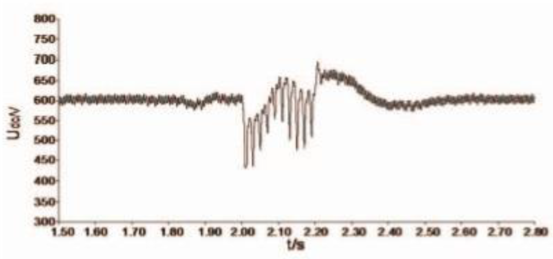
Figure 10.
Output Voltage Characteristic Curves for 6 & 12 pulse chargers [17].
Figure 10.
Output Voltage Characteristic Curves for 6 & 12 pulse chargers [17].
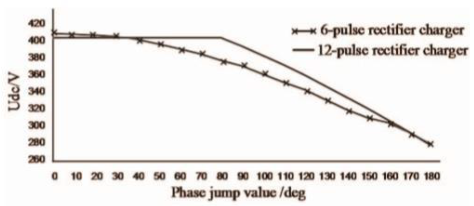
Figure 11.
Output Voltage Characteristic PWM Rectifier charger [17].
Figure 11.
Output Voltage Characteristic PWM Rectifier charger [17].
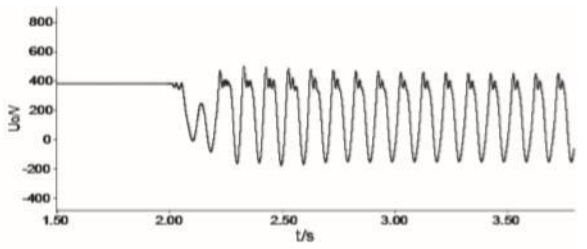
Figure 12.
PWM Rectifier Output Voltage Waveform [17].
Figure 12.
PWM Rectifier Output Voltage Waveform [17].
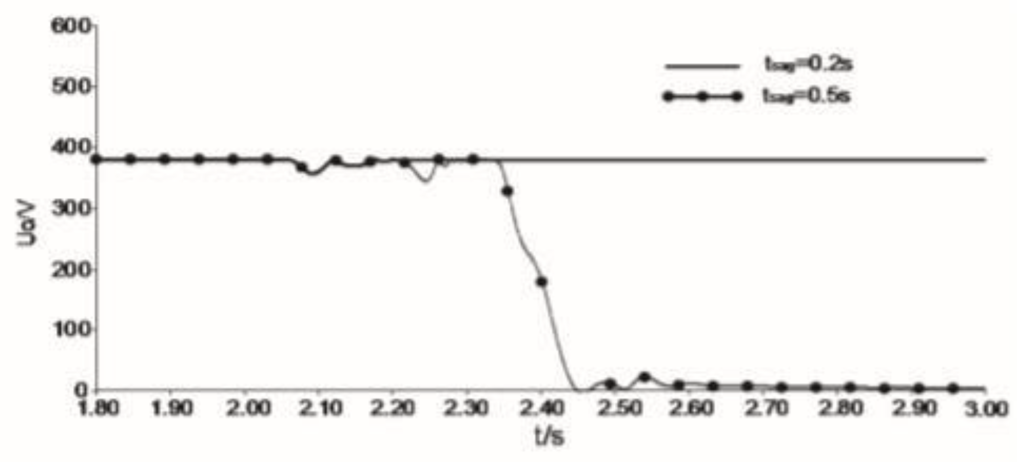
Figure 14.
No. of PEVs that remain connected after a 300msec voltage sag on a node of a feeder [9].
Figure 14.
No. of PEVs that remain connected after a 300msec voltage sag on a node of a feeder [9].
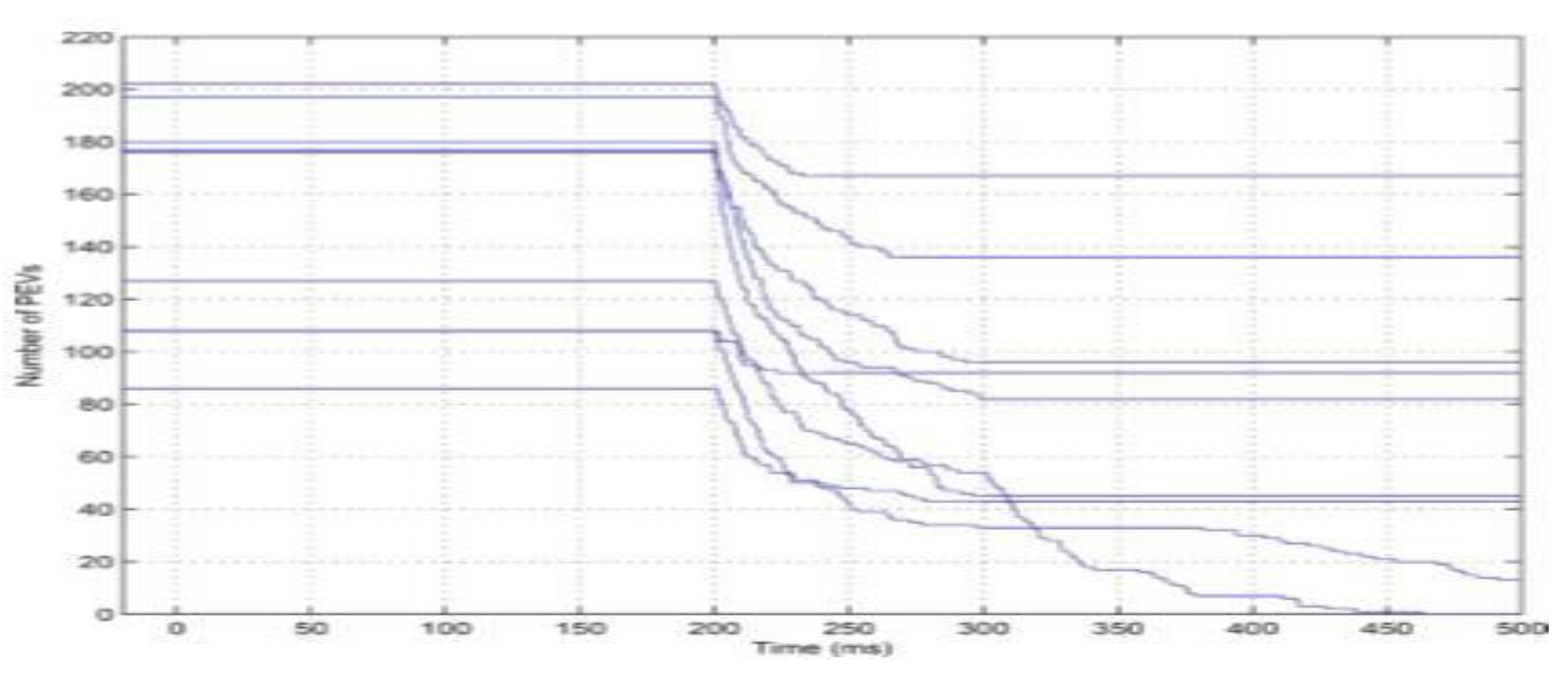
Figure 15.
Post disturbance phase voltage along the main feeder. 20% load drop across 3 phases for all loads [9].
Figure 15.
Post disturbance phase voltage along the main feeder. 20% load drop across 3 phases for all loads [9].
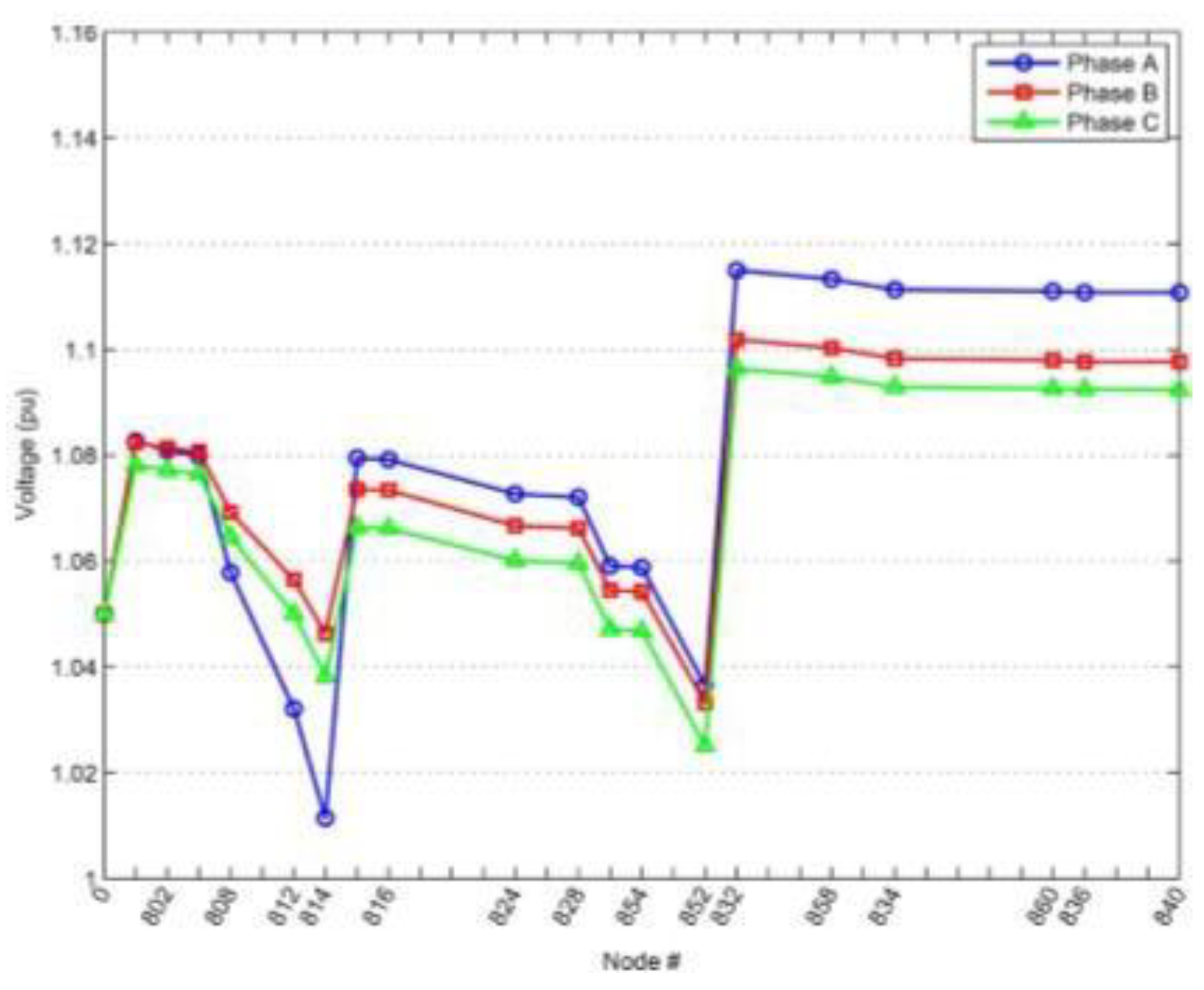
Figure 16.
Schematic with Voltage Compensation.
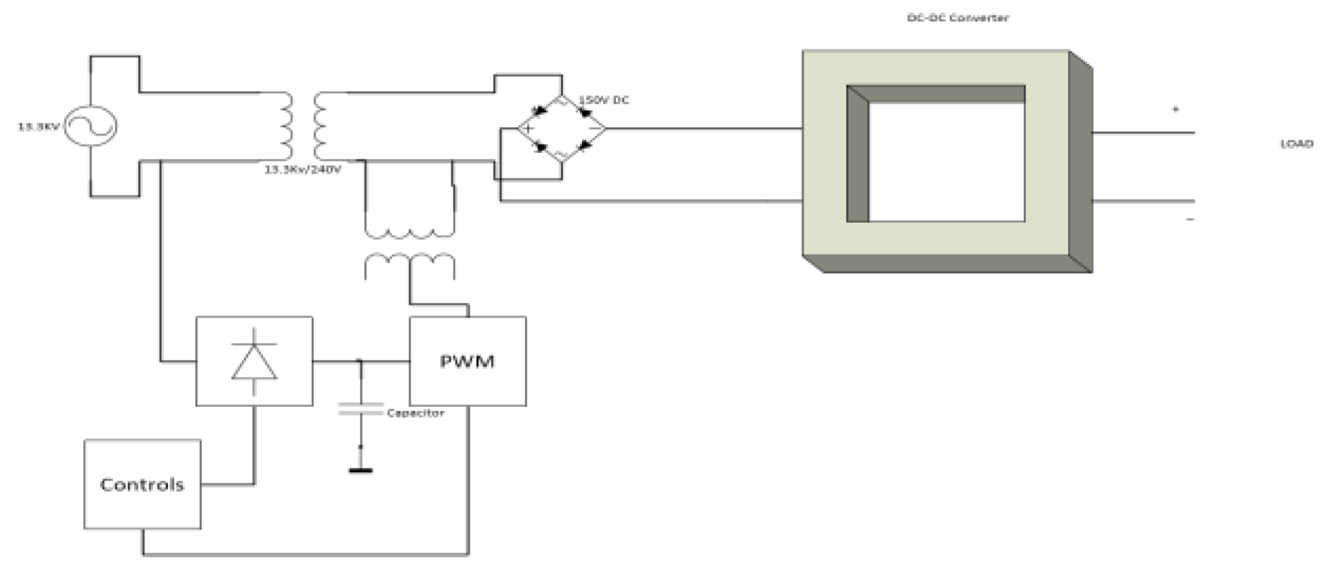
Figure 17.
(a) Voltage Sag on the grid (b) Voltage Sag Compensation (c) Voltage across the Load.
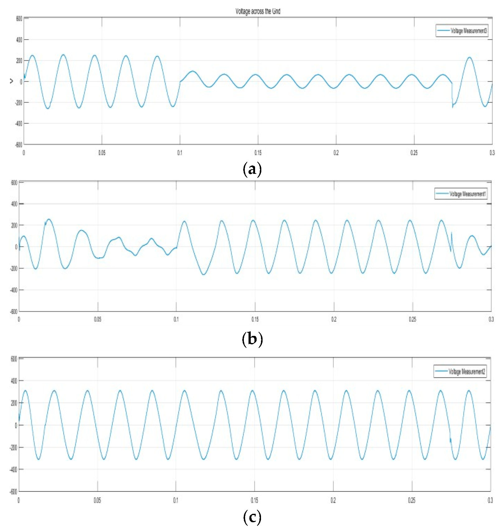

Table 1.
Charging Mode Characteristics [19].
Table 1.
Charging Mode Characteristics [19].
| Charging Mode | Application | Characteristic |
|---|---|---|
|
Mode 1 |
slow charging from a household type socketoutlet |
16 A and not exceeding 250 V a.c. single- phase or 480 V a.c. three-phase, at the supply side, and using power and protective earth conductors. |
|
Mode 2 |
slow charging from a householdtype socketoutlet with an in- cable protection device |
32 A and not exceeding 250 V a.c. single- phase or 480 V a.c. three-phase using standard sockets. |
|
Mode 3 |
slow or fast charging using a specific EV socket-outlet with control and protection function installed |
High currents up to 250 A require specialized cables |
|
Mode 4 |
Fast Charging using an External Charger |
Currents upto 400A |
Disclaimer/Publisher’s Note: The statements, opinions and data contained in all publications are solely those of the individual author(s) and contributor(s) and not of MDPI and/or the editor(s). MDPI and/or the editor(s) disclaim responsibility for any injury to people or property resulting from any ideas, methods, instructions or products referred to in the content. |
© 2025 by the authors. Licensee MDPI, Basel, Switzerland. This article is an open access article distributed under the terms and conditions of the Creative Commons Attribution (CC BY) license (http://creativecommons.org/licenses/by/4.0/).
Copyright: This open access article is published under a Creative Commons CC BY 4.0 license, which permit the free download, distribution, and reuse, provided that the author and preprint are cited in any reuse.