

Submitted:
01 August 2025
Posted:
04 August 2025
You are already at the latest version
Abstract
Many immersed tunnels are constructed in alluvial formations within earthquake-prone regions, making seismic resistance a critical aspect of their safety design. During an earthquake, tunnel displacements can lead to slippage between the tunnel and surrounding soil, and may be further amplified by liquefaction. This phenomenon can cause severe structural damage, including tunnel flotation. This paper examines the seismic performance of immersed tunnels, starting with an overview of the deformation mechanisms affecting tunnels, including those induced by ground shaking and failure. Given its significance in large foundation deformations and its impact on tunnel integrity, liquefaction is analysed alongside potential mitigation strategies. The seismic design process for immersed tunnels is discussed in detail, covering analytical approaches, numerical modelling techniques (such as finite element and finite difference methods), and physical modelling. Real-world examples are provided to illustrate key concepts. Finally, the paper summarizes the core factors influencing the seismic response of immersed tunnels and highlights future research directions to enhance their resilience in seismic environments.
Keywords:
seismic response
; immersed tunnels
; soil dynamics
; liquefaction
1. Introduction
An immersed tunnel is an underwater structure composed of prefabricated elements, which are constructed onshore, floated to the site, and then submerged and installed in a prepared trench. These structures are typically shallow, which minimizes hydrostatic pressures, reduces overall tunnel length, and allows for gentler approach gradients compared to bored tunnels. Their adaptable cross-section profiles make them suitable for a range of applications, including highways and combined rail-road systems. Moreover, they are appropriate for diverse geological conditions, including soft alluvial soils and loose permeable sediments found in riverbeds or seabeds - environments where tunnel boring machines have limitations. The off-site (onshore) construction of tunnel elements also facilitates enhanced quality control. Overall, immersed tunnels often represent a viable alternative from both economic and safety standpoints, as noted by [1].
The seismic behaviour of immersed tunnels is strongly influenced by the properties of the surrounding soil, particularly its stiffness [2]. Seismic-induced displacements may be amplified by soil liquefaction, potentially leading to ground failure if the soil experiences significant strength loss. Liquefaction may result in a loss of lateral or vertical support, differential movements or rotations, shake-down settlement effects (caused by densification of granular materials), or flotation of the tunnel. Likewise, uncontrolled movement of the tunnel can lead to overstressing of the structure and joint leakage, making the implementation of appropriate ground improvement measures essential.
Additionally, it is worth noting that the dynamic response of an immersed tunnel is significantly influenced by earthquake characteristics, particularly magnitude and epicentral distance. Long tunnels may be more vulnerable to seismic damage than shorter ones, due to spatial variability in ground motion along their length.
A number of immersed tunnels have been constructed in seismically active regions. Notable examples include the BART Tunnel in San Francisco [3], several tunnels in Japan, the Aktio-Preveza Tunnel in western Greece, and, more recently, the Bosphorus Tunnel in Istanbul and the Busan Tunnel in South Korea [4]. A future immersed tunnel crossing the Tagus River is also planned in a seismically active area. One of the principal challenges in the design of such tunnels is ensuring adequate seismic resistance, as structural damage from seismic events is particularly difficult to repair due to the nature and location of the tunnel.
This paper investigates the seismic performance of immersed tunnels. It begins by exploring the deformation mechanisms affecting immersed tunnels, including those arising from ground shaking and failure. Given its relevance in inducing large deformations to the tunnel foundation and its structural consequences, liquefaction and related mitigation strategies are addressed in detail. The paper then reviews the seismic design process for immersed tunnels, encompassing analytical approaches, numerical modelling techniques (such as the finite element and finite difference methods), and physical modelling. Several case studies are also presented, including the Offshore Transbay Tube, the Posey and Webster Street Tubes, the Waihuan Tunnel, the George Massey Tunnel, and the Hong Kong-Zhuhai-Macau immersed tunnel. Finally, a brief case study is provided on a proposed immersed tunnel crossing the Tagus River downstream of the 25 de Abril Bridge in Lisbon, Portugal, between Algés and Trafaria, with an approximate length of 2.4 km.
2. Types of Deformation
The effects of earthquakes on underground structures generally arise from two main mechanisms: ground shaking and ground failure. As seismic waves arrive at a site, ground shaking induces displacement of the foundation ground and may reduce its strength, thereby imposing additional loads on the tunnel support system. This shaking can lead to structural damage such as cracking, spalling, and, in extreme cases, structural failure [5].
The simplest analytical case of ground shaking involves a P-wave propagating parallel to the tunnel axis, assuming soil–structure interaction is neglected. P-waves can generate longitudinal compression and tension as they travel along the tunnel, inducing axial strains, tensile and compressive forces in the structure, and the opening or closing of tunnel joints (Figure 1). This loading scenario is one of the most critical for immersed tunnels, as it may lead to decompression of joint gaskets, potentially compromising the tunnel’s watertightness.
P-waves may also propagate normal or at a certain angle to the tunnel axis, producing lateral compression and consequently inducing axial, normal, and shear strains within the structure. When the angle of incidence ranges between 0° and 90°, relative to the tunnel alignment, a time delay occurs in wave arrival between opposite ends of the structure. This asynchronous excitation can lead to horizontal bending, with tensile and compressive zones developing on opposite sides of the tunnel (Figure 2).
S-waves, which possess both vertical and horizontal components, deform the tunnel according to their direction of propagation and angle of incidence. These waves can induce longitudinal, normal, and shear strains, as well as vertical and horizontal bending moments in the tunnel. Furthermore, the curvature of the structure may result in joints opening and closing, similar to the effects of P-waves.
St. John and Zahrah [5] presented analytical methods for estimating longitudinal, normal, and shear strains - and their corresponding stresses - as function of the wave incidence angle. These were evaluated for P-, S-, and Rayleigh (R-) waves, both with and without considering soil-structure interaction. The latter case is especially pertinent for immersed tunnels, which are generally stiffer than the surrounding soils (generally soft deposits) and therefore do not conform to free-field ground deformations. Shear waves are typically responsible for generating the largest bending moments, shear forces, and axial loads in the tunnel.
Racking deformation arises from SH-waves propagating vertically through the soil, perpendicular to the tunnel axis. Due to inertial effects within the ground layers, this produces horizontal distortion of the ground mass. The racking deformation imposed on the structure corresponds to the relative displacement between the soil at the top and bottom of the tunnel. For a rectangular tunnel cross-section, such distortion (Figure 3) generates significant bending moments and shear forces - especially at rigid wall-slab connections - that must be accounted for in the design. If the tunnel is considerably stiffer than the surrounding soil, as is typical for immersed tunnels, numerical analysis incorporating soil-structure interaction is essential. In such cases, the actual racking deformation is expected to be less than that predicted from free-field deformation [5].
Immersed tunnels are usually embedded in soft ground near the surface, which significantly influences their dynamic response. In some cases, the limit friction may be exceeded at the soil-structure interface, leading to slippage. Additionally, soft surface layers may experience amplified motion due to earthquake-induced liquefaction, which can result in a severe loss of soil strength and lead to ground failure. The tunnel’s behaviour is further influenced by variations in subsurface topography and geology, changes in overburden thickness, the presence of fault lines or dislocations, slope movements, and shear zones [2]. Thus, the most critical ground failure mechanisms for immersed tunnels include liquefaction, fault displacement, and slope instability.
Liquefaction may cause the immersed tunnel to either float or sink, depending on the net pore pressures in the soils beneath the structure. Fault displacements or shear movements in the bedrock may be mitigated by maintaining a sufficient thickness of soft soil between the tunnel and the underlying rock [7]. Furthermore, increasing joint flexibility can help accommodate fault-induced offsets and reduce structural damage. Slope instability can also be triggered by either ground shaking or liquefaction. This is particularly relevant near tunnel portals located on inclined riverbanks or coastal slopes, as well as underwater slopes, all of which may become susceptible to seismic-induced sliding.
3. Liquefaction and Mitigation Measures
Liquefaction of soils surrounding an immersed tunnel can have severe consequences, including the loss of lateral or vertical support and significant displacements or rotations of the tunnel. In extreme cases, such as the 1964 Niigata earthquake in Japan, horizontal displacements of 6 to 8 m were recorded. Additional movement may occur due to shake-down settlement, a phenomenon where granular soils densify naturally as their structure collapses under seismic loading. Any uncontrolled movement of the tunnel structure is undesirable, as it can lead to overstressing and joint leakage.
Buoyancy is another critical issue associated with liquefaction. During liquefaction, the surrounding soil behaves like a dense liquid with an effective unit weight of approximately 20 kN/m³, almost twice that of the tunnel, typically around 10.5 kN/m³. As a result, the tunnel may experience uplift. A buoyancy assessment is essential to evaluate the potential for upward movement, accounting not only for the tunnel’s weight but also for the contribution of the engineered backfill and any ground improvement. Although a simple analysis suggests the tunnel would float, this assumes uniform ground conditions and neglects restraining effects. The interaction between the tunnel and the selected backfill - which is designed to resist liquefaction - adds complexity, as the extent to which the backfill behaves monolithically with the tunnel is not easily quantified.
Liquefaction can also trigger submarine landslides, particularly in foreshore areas, where shallow material may flow into the deeper channel and increase overburden on the tunnel. Such effects can lead to increased post-earthquake settlement, which must be anticipated and accounted for in design.
Given the complexity and unpredictability of ground behaviour during liquefaction, preventing its occurrence is essential. This requires a comprehensive assessment of the potential for liquefaction in the supporting ground, followed by appropriate ground improvement measures. Since it is often not feasible to alter the tunnel alignment to avoid liquefiable materials, strengthening the soil through increased density, shear strength, or improved drainage usually becomes the only viable solution [4].
Several well-established ground improvement techniques have been used successfully for immersed tunnels, which are briefly described next.
3.1. Stone Columns and Vibro-Replacement Techniques
Stone columns improve seismic behaviour by increasing the shear modulus of the soil and limiting the buildup of pore water pressure. When combined with vertical drains, they facilitate rapid consolidation, reduce differential settlement, and provide escape paths for excess pore water during seismic shaking [4]. Typically, stone columns have diameters ranging from 0.6 to 1.0 m and are installed on a grid with approximately 2-meter spacing, arranged in square or diamond patterns, depending on design objectives regarding bearing capacity, density, or relief of excess pore water pressures.
To ensure effectiveness, gravel used in the columns must be narrowly graded to promote self-compaction and maintain permeability. Some clogging from silt and some sediment infiltration may occur, but due to the column’s large diameter, water flow paths are generally preserved. However, vertical drains may be included to enhance performance. Crucially, the stone columns must be connected to a permeable layer, such as a gravel foundation bed, extending through a coarse backfill to the seabed or riverbed surface, enabling dissipation of pore water pressure.
Vibro-replacement techniques densify and reinforce liquefiable soils. The drainage capacity of the columns - and its variability along their length - significantly influences their effectiveness and must be accounted for in the design [8].
3.2. In-Situ Soil Mixing
In-situ soil mixing allows for deep ground improvement by using a set of augers to penetrate the ground and, during their withdrawal, injecting and mixing cement with the soil to form stiffened columns. This method can create treated panels or walls and is particularly useful in high liquefaction potential zones. It enhances bearing capacity and stiffness of the ground, reduces settlements, and can be adapted for deep offshore conditions (up to 70 m below seabed level) [4].
In-ground walls formed through this technique also [8]:
- Reduce earthquake-induced shear strains in the treatment zone;
- Limit pore pressure generation;
- Contain untreated soil and contribute to overall shear strength;
- Act as barriers to excess pore pressure migration from untreated soils;
- Help mitigate flotation by confining liquefied soil beneath the tunnel.
3.3. Sand Compaction Piles (SCP)
SCPs are installed by vibrating a sleeve filled with sand into the ground and releasing the sand during withdrawal. This displacement method densifies loose deposits and has proven effective for increasing bearing capacity and reducing settlement. SCPs are suitable for marine environments and can treat depths up to 70 m. Commonly, they are arranged on triangular or rectangular grids with diameters of 1.5 to 2 m for offshore applications.
3.4. Colloidal Silica Grouting
This more recent method involves injecting a colloidal silica gel that binds sand particles and fills pore spaces, reducing permeability. Colloidal silica gel also encapsulates the soil structure, significantly enhancing resistance to cyclic loading. It decreases its volume upon compression, allowing less excess pore water pressure to develop, and does not significantly increase soil stiffness, thus avoiding amplification of seismic waves. Under suitable seepage conditions, colloidal silica can be injected upstream and transported via groundwater to the target liquefiable zone beneath the tunnel - either before or after the installation of tunnel elements.
3.5. Expansive Polyurethane Resin Injections
Expansive polyurethane resin injections is another recent method, used to densify the ground, as additional material is injected into a relatively constant soil volume, filling voids and increasing soil stiffness. This technique also enhances composite stiffness, induces cementation, and increases horizontal stresses. For immersed tunnels, this method is best applied before trench excavation, up to the base of the tunnel, so that a minimum confining stress - provided by the weight of overlying sand and foundation and protection layers - is present at the injection zone.
4. Seismic Design
The seismic hazard at a tunnel site can be quantified through a project-specific seismic hazard assessment. This involves estimating bedrock motion by evaluating historical seismicity, relevant seismic data, ground motion characteristics, regional seismic hazard assessments, site geology, and the activity of nearby faults with the potential to generate significant seismic events.
Seismic design of tunnel structures differs fundamentally from that of aboveground structures. Tunnel behaviour is primarily displacement-controlled, as the structure tends to move in concert with the surrounding ground. The tunnel’s inertia is generally negligible relative to that of the soil, except at portals with aboveground elements such as buildings or ventilation shafts. In immersed tunnels, the structure is typically stiffer than the surrounding soil, making soil-structure interaction a key consideration.
Thus, the dynamic behaviour and stability of the surrounding ground are crucial to the seismic design of immersed tunnels. Ground displacement - particularly differential displacements along the tunnel axis during earthquakes - is the dominant design consideration.
Site-specific amplification or attenuation effects due to topography and geology can be assessed using numerical modelling. These analyses provide estimates of the effective ground motions at the tunnel, from which structural strains can be determined. Applying appropriate stress-strain relationships enables the derivation of corresponding internal forces [2]. Accurate conversion of strains into forces requires a clear understanding of the tunnel’s structural response. Since both steel and concrete immersed tunnels typically contain similar volumes of concrete, the tensile behaviour of concrete - particularly its tendency to crack under large seismic loads, unless heavily compressed or prestressed - plays a critical role in overall structural performance [2].
Seismic loading induces horizontal and vertical bending in the tunnel, resulting in reciprocal shear forces at the joints. Differential settlements between adjacent tunnel segments can further introduce vertical shear. These shear forces must be transferred across the joints - primarily through shear keys. Therefore, joint design must account for both compressive and shear forces. The general steps in the seismic design process are outlined in Figure 4.
Kiyomiya [9] identified three main approaches used in Japan for the seismic design of immersed tunnels: (1) the seismic coefficient method, (2) the seismic deformation method (both analytical), and (3) dynamic response analysis (numerical method). According to [9], the internal forces and displacements in tunnel components should be evaluated using both the seismic coefficient and seismic deformation methods (for cross-sectional behaviour), and dynamic response analysis (for longitudinal behaviour), incorporating effects of surrounding ground, topography, and geology. Structural deformations, ground response, inertial effects due to the tunnel’s dead weight, and additional earth pressures must also be considered.
The study of dynamic soil-structure interaction for linear underground structures under seismic loading is a complex engineering challenge. Hashash et al. [6] and Nam et al. [10] reviewed various methodologies for quantifying seismic effects on underground structures and investigated soil-structure interaction. These include analytical approaches and numerical modelling techniques, primarily based on finite element or finite difference methods. In addition, physical modelling is used to study immersed tunnel response - particularly in critical components such as joints.
4.1. Analytical Approaches
Analytical methods for estimating strains and stresses in structures subjected to ground motion are typically based on the theory of wave propagation in an infinite, homogeneous, isotropic, elastic medium, coupled with the theory of an elastic beam on an elastic foundation to incorporate soil-structure interaction effects [5]. This approach, only applicable to a limited range of problems, requires the definition of a foundation modulus - introducing a degree of subjectivity in its application.
St. John and Zahrah [5] applied this analytical method to the Offshore Transbay Tube (TBT) of the Bay Area Rapid Transit (BART) system in San Francisco. The analysis involved calculating the maximum internal forces (bending moments, shear forces, and axial forces) due to both horizontal and vertical shear waves, and then combining these to obtain the total design forces. When soil-structure interaction was considered, the maximum bending moment and shear force were reduced by factors of approximately 3 and 2, respectively.
Kuesel [3], using the theory of wave propagation, derived an analytical expression for the maximum axial strain induced by an oblique shear wave in the TBT. This wave includes both transverse (producing bending) and longitudinal (producing compression-tension distortion) components:
where is the critical wavelength, assumed to be six times the immersed tunnel width in the bending plane (deep beam action), and is the amplitude associated with , derived from the design earthquake response spectrum.
The tunnel was also designed to resist racking. The shear distortion magnitude was estimated using:
where is the shear distortion angle (in radians), is the overburden depth (m) and is the average shear wave velocity (m/s). This expression approximates the shear deformation of a vertically cantilevered soil column subjected to a horizontal base excitation, assuming a linear variation in shear modulus with depth.
Okamoto et al. [11] developed a mathematical model for the seismic analysis of immersed tunnels, treating the structure as a beam supported by elastic or inelastic springs, both transversely and longitudinally. Ground motion resulted from shear wave vibration of the surface layer, with only the fundamental vibration mode considered. The ground at each point along the tunnel axis was modelled as a mass-spring system, with mass and spring stiffness values chosen to match the natural period of the system to that of the ground. Ground displacements were obtained by multiplying the mass displacement by the corresponding participation factor for the fundamental vibration mode.
In the seismic coefficient method [9], a force-based approach, inertial forces in three orthogonal directions are computed by multiplying the structure and soil masses by the respective design seismic coefficients. Higher coefficients are used for critical elements such as ventilation towers, with large inertial forces. Seismic earth pressures are calculated using the Mononobe-Okabe method. Vertical overburden pressures are adjusted by multiplying the weight of the soils by (1 ± kv), where kv is the vertical design seismic coefficient. This approach can be used for the design of the ventilation tower and approach structures.
In contrast, in the seismic deformation method [9], a displacement-based approach, the ground displacement is estimated at the tunnel longitudinal axis depth using:
where is the normalized response velocity per unit seismic coefficient, is the natural period of the surface ground, is the horizontal seismic coefficient at the bedrock, and is the surface layer thickness. The tunnel is assumed to follow ground movement, with minimal excitation or resonance.
For transverse analysis, the tunnel cross-section is modelled as an elastic frame. Slabs and walls are idealized as beams.
Neglecting soil-structure interaction, the maximum axial force occurs at a 45° wave incidence angle, and the maximum bending moment and shear force occur with wave propagation parallel to the tunnel axis. Assuming harmonic motion, the peak forces are:
where is the Young’s modulus, is the cross-sectional area and is the moment of inertia of the lining, is the maximum ground displacement, and is the wavelength.
When soil-structure interaction is considered, the tunnel is modelled as a beam connected to ground with a series of idealized springs in both longitudinal and transverse directions. The modified equations become:
where and are the longitudinal (axial) and transverse (shear) spring constants, respectively.
Vrettos [12] noted that this method is conservative, as it assumes a single, critically oriented shear wave, and a value of independent of wavelength, while actual ground displacement amplitude typically decreases with increasing wavelength. Thus, as a reliable and physically sound estimate of the wavelength of the relevant incident seismic wave is usually difficult to determine, he proposed simplified, wavelength-independent estimates of peak forces:
While various methods exist for estimating spring constants, reliable analytical evaluation remains difficult. Vrettos [12] recommends finite element (FE) analysis with nonlinear soil models for realistic assessment. Nevertheless, St. John and Zahrah [5] derived a closed-form expression, from a 2D plane-strain solution for a static sinusoidal point load in an infinite elastic, isotropic and homogeneous medium:
where and are the shear modulus and Poisson’s ratio of the soil, respectively, and is the tunnel’s equivalent diameter.
4.2. Numerical Methods
Numerical methods offer a powerful tool for analysing and designing complex structures, serving as a key approach for evaluating the seismic performance of immersed tunnels. These methods enable the investigation of spatial variation effects in ground motion and the dynamic interaction between soil and structure.
In the finite element method (FEM), the continuum is discretized into finite elements, each assigned specific material and constitutive properties. The state equations for each element are then assembled into a global system of equations representing the entire structure [5]. In contrast, the finite difference method involves discretizing the equations of motion of the soil-structure system by approximating derivatives with finite difference expressions. For ground modelling, block elements or two-dimensional plane-strain elements are typically used, while beam elements represent the immersed tunnel. Despite the availability of 3D models, simplified numerical approaches such as mass-spring equivalent models are often employed due to the high computational cost and memory demands of full 3D simulations.
Kiyomiya [9] introduced a 2D multi-mass-spring model in which the surface soil layer is divided into vertical slices, each represented by a mass-spring-dashpot system. Springs and dashpots connect the masses to the bedrock and they are also interconnected along the tunnel axis via springs and dashpots, simulating the longitudinal soil behaviour. The dynamic response is governed by the equation:
where , and represent the mass, damping and stiffness matrixes, respectively; , and are the acceleration, velocity and displacement vectors; and is the vector of input accelerations. The tunnel is modelled as a beam connected to the ground via springs, which transmit ground motion to the tunnel ends. This formulation enables the inclusion of elements such as joints and ventilation towers in the seismic analysis.
Building upon this model, a quasi-3D approach was developed for more complex ground conditions. Here, the surface layer is represented by plate elements and masses, and each mass is connected to the bedrock through springs/dashpots, allowing for improved simulation of three-dimensional effects.
Anastasopoulos et al. [13] applied a finite element model to study joint deformations in an immersed tunnel subjected to combined longitudinal and lateral seismic vibrations. The model was based on a 70-meter-deep tunnel located in a seismically active region of Greece and simulated using beams linked to the ground via calibrated springs, dashpots, and sliders. Free-field acceleration time histories were applied at spring supports with time lags to simulate wave passage effects. Tunnel elements were modelled using shear-flexible beam elements, while joints were represented by 64-node perimeter frames connected by single degree of freedom nonlinear springs, representing the stiffness of the joint (Figure 5). Gina gaskets and shear keys were modelled using axial springs in the longitudinal direction and gap elements in the transverse and vertical directions, respectively. The nonlinear dynamic analysis of the tunnel highlighted the influence of joint characteristics - such as Gina gasket deformation and shear key allowance - and tunnel segment length in the transverse and vertical deformation of the tunnel. Results indicated that appropriately designed joint gaskets, with increased thickness, and shorter tunnel elements reduce the risk of excessive tension or compression in the joints during seismic loading. In fact, while the modern trend is to go for longer elements, of the order of 150-200 m, smaller lengths may be dictated by seismic considerations. Furthermore, longitudinal hydrostatic prestressing of the tunnel and the end supports provide, respectively, a restoring force and a substantial constraint, which mitigate longitudinal sliding.
Expanding on this methodology, Zhang et al. [14] developed a spatial nonlinear mass-spring model to investigate the seismic behaviour of an immersed tunnel-foundation system. The behaviour of the joints between elements and segments was simulated using distributed multi-node frame elements, including shear pins in segment joints (Figure 6). The study examined the influence of temperature and prestressing on the tunnel seismic response. Results showed that cooling (temperature decrease) had a more adverse effect on joint deformation and segment internal forces than heating, by reducing compression. While axial forces were sensitive to temperature variation, bending moments were largely unaffected. Retaining prestress cables improved segment joint sealing, but negatively affected immersion joint sealing, as Gina gasket compression is higher when the cables are cut.
Oorsouw [15] studied the "worming and snaking" effects using simplified beam models, without considering soil-structure interaction, to assess the impact of parameters such as seismic wavelength, construction depth, tunnel element length, and rubber gasket stiffness in segment and immersion joints. He concluded that gasket properties and seismic wavelength were the most influential factors. The Gina gasket’s compressibility and the segment water sealing profile’s elongation capacity dictated axial deformation, while rotational capacity and Gina gasket quantity affected snaking behaviour. The segment joints were found to act relatively stiff until their moment capacity was reached.
Zhang et al. [16] proposed a structure-water-sediment-rock interaction model to evaluate a linear elastic immersed tunnel response to obliquely incident seismic waves, considering the dynamic interaction between the structure and the surrounding ground. A viscous-spring absorbing boundary simulated the wave radiation effect of the far field domain, and the free field response was calculated through site earthquake response analysis and translated into equivalent boundary loads. Their model had a width L of 120 m, a water depth d(1) of 17 m, a variable sediment thickness d(2) between 0 m and 9 m and a rock thickness d(3) of 37 m (Figure 7). The effects of the thickness, porosity, and permeability of the surrounding ground and of the seismic wave incident angle were studied. Results showed that greater sediment thickness and lower porosity increased peak horizontal displacement, while peak stress rose with the angle of wave incidence.
Chen et al. [17] developed a 2D integrated model for time-history analysis of an immersed tunnel in a marine environment under bidirectional seismic excitation (Figure 8). The width of the model was 800 m, and the thicknesses of the soil layer 1 (clay), of the soil layer 2 (sand) and of the bedrock were 40 m, 30 m and 10 m, respectively. The depth of the seawater was considered 20 m. The model incorporated nonlinear soil behaviour using the Davidenkov model and employed the Coupled Acoustic-Structure (CAS) method for dynamic soil-water interaction. The influence of soil-tunnel contact technique, seismic input, seawater effects, and ground reinforcement via sand compaction piles (SCPs), on the performance of an immersed tunnel, was studied under three peak bedrock accelerations, ranging from 0.2 to 0.4 g. The distribution of tensile damage, of the maximum drift ratio between the top and bottom slabs of the tunnel, of the maximum bending moment, and of the tunnel inclination angle in the transverse direction were analysed. Findings indicated that bidirectional input led to more severe tunnel responses, except for the maximum drift ratio. Additionally, the overlying seawater increased the tensile damage and amplified the uneven settlement of the tunnel for higher peak bedrock accelerations. While SCPs can effectively reduce reduced settlement and deformation, they may make the tunnel more susceptible to damage and failure during seismic events. The bending moments and tensile damage increased at critical corner locations of the tunnel section, especially under higher seismic intensities. Also, the maximum drift ratio increased with the implementation of SCPs, and this increase became more pronounced for higher seismic input intensities. The uneven settlement of the tunnel cross-section was amplified only for lower seismic input intensities.
Chen et al. [18] analysed the dynamic response of the Zhoutouzui immersed tunnel using a 3D finite-infinite element model (Figure 9), including varying the stiffness of the joints. The mesh near the boundaries of the model was formed by infinite elements (light green in Figure 9) and the immersion joints were simulated with springs. They found that increasing joint stiffness led to higher axial forces and bending moments in the joints.
Zhou et al. [19] modelled the nonlinear seismic response of a 3-element immersed tunnel subjected to obliquely incident SV waves in a horizontally layered site (Figure 10). Using an accurate dynamic stiffness matrix and viscous-spring boundary conditions, they observed increased overall displacement with increasing incident angle. Maximum stress on the shear keys and deformation of the immersion joints occurred near the critical wave angle. Crack analysis of the tunnel cross-section suggested reinforcement was needed at corners, midspan of the top slab, and horizontal shear key connections with the base slab.
Xiao et al. [20] conducted a pseudo-static numerical analysis of an immersion joint (Figure 11), modelling steel shear keys behaviour with a bilinear elastic-plastic model and Gina gaskets response with the Mooney-Rivlin model. The vibration isolation bearings between shear keys were indirectly simulated using a gap closure tolerance and the anchor bolts connecting the steel shear keys to the concrete elements were substituted by an equivalent elasto-plastic layer. Results showed that joint flexural stiffness increased nonlinearly with axial force. Under cyclic shear loading, higher axial forces promoted elastic-like behaviour of the Gina gasket, as its compressive stiffness increased, while lower axial forces led to hysteresis.
Lyngs [21] investigated the seismic response of an immersed tunnel and gasket damage using a closed-form solution, a Winkler-type model (without considering ground elements), and a full 3D continuum model. While the Winkler model was deemed unsuitable for the seismic design of tunnels with non-uniform cross-sections, comparative analysis revealed that soil properties and stratification, together with the earthquake magnitude, significantly influence tunnel damage. Interestingly, tunnel joint modelling had minimal impact on gasket deformation.
The use of 2D and 3D finite element models to evaluate immersed tunnel seismic performance is further illustrated in the case studies presented in Chapter 5.
4.3. Physical Models
Physical models have been extensively employed to investigate the seismic performance of immersed tunnels, focusing on tunnel flotation, the influence of the overlying water layer, and the mechanical behaviour of tunnel joints.
Uplift of buried structures in liquefiable soils, including immersed tunnels, has been observed during large earthquakes [22,23], and has also been documented in shaking table tests [22,24,25] and centrifuge experiments [26,27,28]. Significant uplift typically occurred under strong shaking conditions.
For example, Yasuda et al. [25] analysed the flotation of buried pipes, demonstrating that uplift magnitude and rate decreased with increasing pipe unit weight and soil relative density. Uplift was more pronounced when a larger volume of liquefiable soil surrounded and underlay the pipe, while allowing pore pressure dissipation substantially reduced uplift. Sasaki and Tamura [27] further found that uplift was predominantly accumulated during shaking. They observed that increased liquefiable soil thickness beneath the structure and a larger volume ratio between liquefiable soil and structure led to greater uplift. Conversely, higher soil relative density reduced uplift, while structure weight and groundwater level had minimal influence.
Travasarou et al. [29], through centrifuge testing, identified uplift as a displacement-limited ratcheting mechanism governed primarily by co-seismic soil movement beneath the tunnel. The liquefied soil, softened and heavier, pushed the tunnel upward and laterally (Figure 12). Displacements from shear deformation during strong shaking were not recovered post-earthquake.
They also proposed a secondary uplift mechanism driven by pore water migration under hydraulic gradients during or after shaking. Excess pore pressure generated beneath the tunnel by contractive soils caused water to flow both beneath the tunnel and toward the surface. Post-shaking, continued water flow led to volumetric soil expansion beneath the tunnel and residual uplift. As pore pressures equalized, water flowed out from beneath the tunnel and it partially settled, reversing much of the post-earthquake uplift.
In some scenarios, high shear stresses resulting from differential weight between the structure and surrounding soil, combined with severe liquefaction-induced strength loss, could generate a net upward force on the structure, resulting in large, uncontrolled uplift - suggesting the presence of a force-based uplift mechanism.
In summary, uplift is primarily influenced by:
- the extent and thickness of liquefiable soil (particularly beneath the structure);
- the soil’s relative density;
- the weight differential between the tunnel and the surrounding ground;
- the amplitude and duration of seismic shaking;
- volumetric dilation due to pore water migration and heaving of soft soils.
Regarding the influence of foundation soil and overlying water layer on the seismic response of immersed tunnels, Cheng et al. [30] conducted a series of shaking-table tests to assess it. Considering the common placement of such tunnels beneath rivers or seas, the study was based on the Hong Kong-Zhuhai-Macau (HZM) project, which includes an immersed tunnel with 33 elements, divided in 8 segments each. The scaled model (1:30) comprised three segmented elements and two simplified flexible joints, omitting scaled shear keys due to strength limitations.
Tests were performed in dry sand, saturated sand, and saturated sand with a 0.20 m thick overlying water layer, placed inside a laminar shear container, under identical horizontal seismic excitations (PGA ranged from 0.1 to 0.4 g). Results indicated that liquefaction significantly altered seismic wave propagation and the tunnel dynamic response by dissipating energy and reducing acceleration amplification. However, the overlying water layer had negligible impact on the dynamic performance of the ground or tunnel. Simplified joints reduced acceleration transmission between elements and were found significant for seismic design, despite lacking shear keys and gaskets. Additionally, stronger excitations generated excess pore pressures more rapidly, peaking at the ground surface. Soil below the structure exhibited slower particle movement and reduced liquefaction, attributed to increased consolidation stress due to the additional structural load.
Chen et al. [31] also examined an immersed tunnel response under uniform seismic excitation, both in the longitudinal and transverse directions, using a four shaking-table array with a 1:60 scale model, placed inside a rigid container which spanned the four tables. The tunnel model joints included prestress cables, Gina gaskets, and shear keys. Testing involved stepwise excitation up to 1.5 g. As shaking intensity increased in free-field tests, soil stiffness decreased and soil gradually softened. Tunnel seismic responses were clearly affected by surrounding ground conditions, and immersion joint forces grew with input intensity.
Wang et al. [32] investigated seismic responses of two immersed tunnel elements under varying seismic waves (PGA: 0.1-0.4 g) and water levels (Figure 13), using a single DOF shaking-table and a rigid container with polystyrene foam boards glued to its walls, to absorb the seismic waves and avoid their reflection. The tunnel polystyrene model, scaled at 1:100, included ballast steel plates and simplified joints, constituted by flexible plastic foam Gina and Omega gaskets and shear keys made with snap fasteners (Figure 14). Soil was pre-treated by drainage consolidation and vibration to prevent liquefaction. Results showed that seismic wave amplitude and other characteristics influenced tunnel response, which increased with the amplitude. Water presence amplified earthquake waves, with water level influencing this amplification, and especially affecting tunnel transverse strains, which were higher near joints.
Xiao [33] conducted experimental studies on an immersion joint subjected to axial, shear, and bending loads. The model included two tunnel elements, with an immersion joint in between, with a rubber seal and two types of shear keys (steel and concrete). Both the axial stiffness and the flexural stiffness of the joint were derived through load-deformation curves. Increasing axial force in the joint, also subjected to bending, enhanced its flexural stiffness and reduced differential displacements. Static and dynamic shear stiffness also increased with axial load, particularly under dynamic loading due to the Gina gasket rubber compression. Nonetheless, the increase of dynamic stiffness varied with the input frequency. In both cases, the stiffness of the joint increased, when compared with the element.
Additionally, Xiao [33] determined the failure mode and the shear capacity of the joint. However, experimental shear capacities differed from design values due to staggered shear key failure. Rubber bearings improved shear force distribution in steel keys, while asymmetric installation of the shear keys led to racking in concrete keys. The Gina rubber gasket significantly contributed to shear resistance.
To mitigate seismic effects, Buckling Energy Dissipation Devices (BEDDs) can be installed at tunnel joint sidewalls. These steel plate core devices, encased in silicone and concrete-filled steel tubes to restrain buckling, are designed to be activated prior to the occurrence of non-elastic deformations or structural damage, with the goal of dissipating most of the earthquake energy. Large-scale tests, conducted on an immersion joint subjected to compression-bending, showed that BEDDs improved joint hysteretic behaviour, bending resistance, and flexural stiffness, though rubber seals remained the primary load-bearing component under bending.
Yuan et al. [34] studied vertical shear behaviour of an immersion joint model with steel shear keys under multidirectional loading (Figure 15). A custom loading system enabled testing under various load combinations: compression-vertical shear with increasing longitudinal compression, or increasing vertical shear until failure at constant compression; bidirectional shear, with increasing vertical shear, and fixed longitudinal compression and transverse shear. Results showed that vertical shear stiffness increased with longitudinal compression due to enhanced Gina gasket friction. Transverse shear loads further contributed to this increase, due to friction generated by shear force sharing among horizontal keys. However, the ultimate vertical shear capacity of the joint was lower than the theoretical sum of individual vertical keys shear capacities, indicating non-simultaneous load sharing.
5. Immersed Tunnels Seismic Performance
The seismic performance of six immersed tunnel projects is examined in detail: the Offshore Transbay Tube (TBT), the Posey and Webster Street Tubes, the Waihuan Tunnel, the George Massey Tunnel, the Hong Kong-Zhuhai-Macau (HZM) immersed tunnel and the proposed Algés-Trafaria crossing.
5.1. The Offshore Transbay Tube (TBT)
The Offshore Transbay Tube (TBT), part of the Bay Area Rapid Transit (BART) system, is a 5.8 km-long immersed railway tunnel connecting San Francisco to Oakland. Located in the seismically active San Francisco Bay Area (Figure 16), it was constructed in the late 1960s.
The tunnel was installed in a trench excavated in natural soil, reaching a maximum depth of approximately 40 m. After trench excavation, a 1.2 m-thick gravel bedding layer was placed and levelled (Figure 17). A total of 58 composite tunnel elements - each 100 m long and composed of an external steel shell with internal reinforced concrete - were then immersed and joined. Gravel backfill was tremied around the tunnel up to mid-height, followed by the placement of sand fill to provide a minimum cover of 1.5 m above the structure. Over time, natural sedimentation led to the formation of a soft, impermeable surficial mud layer [29].
Although the TBT does not intersect any active faults directly, it lies in close proximity to major fault systems. Specifically, it is situated approximately 14 km from the San Andreas Fault and 9 km from the Hayward Fault, both of which are capable of generating magnitude 7-8 earthquakes and exhibit slip rates of 0.017 m/year and 0.009 m/year, respectively.
To accommodate potential seismic displacements from nearby fault activity, a specially designed terminal joint was implemented at both ends of the tunnel [4]. This telescopic sliding joint allows for triaxial movement while maintaining watertight integrity (Figure 18). It was engineered to accommodate longitudinal displacements of 0.08 m and vertical or transverse displacements of 0.15 m. Precompressed rubber gaskets slide on Teflon-coated radial and circumferential bearing surfaces to permit movement. Tensioned cables and spherical bearings ensure proper alignment and load transfer. Seals are incorporated to prevent leakage during joint articulation. The movement capability integrates allowance for creep, which is likely to occur over time with repeated seismic movements. The joint also includes mechanical stops to limit excessive displacement and mitigate the risk of joint opening.
The tunnel demonstrated its seismic resilience during the 1989 Loma Prieta earthquake (magnitude 6.9), which had a peak ground acceleration (PGA) of approximately 0.2 g at the tunnel site and an epicentre 95 km away. Despite widespread infrastructure damage across the region, the TBT remained operational and was reopened only three hours after the earthquake, making it the only functional public transit link at the time.
While liquefaction of the backfill was anticipated under design-level seismic events due to its loose placement, no instances have been reported to date. The gravel backfill is relatively permeable, facilitating rapid dissipation of excess pore pressures. However, the presence of low-permeability surficial soils may result in localized entrapment of pore water.
Dongdong et al. [36] investigated the vulnerability of the TBT to uplift induced by liquefaction of surrounding soils. Two centrifuge model tests were conducted at the University of California, Davis [37], simulating representative trench geometries and soil conditions along the TBT alignment, including both stiff and soft clay substrates. The results were used to calibrate numerical models for seismic design.
Each centrifuge model was subjected to a suite of earthquake ground motions with progressively increasing PGA values (0.01-0.66 g). These included: the 090-horizontal component of the Yerba Buena Island (YBI) recording from the 1989 Loma Prieta earthquake (PGA 0.01-0.14 g); the TCU078 recording from the 1999 Chi-Chi earthquake (magnitude 7.6, PGA 0.05-0.66 g); and a processed signal from the 1992 Landers earthquake (magnitude 7.3, PGA 0.05-0.36 g), referred to as the Joshua Tree motion.
Three uplift mechanisms were identified: (1) a ratcheting mechanism involving sand migration beneath the tunnel with each cycle of relative movement, (2) pore water migration driven by pressure gradients, and (3) bottom heave due to soft clay deformation below the trench [37].
Under the YBI motion, negligible uplift occurred despite excess pore pressures reaching 70-80% of the initial effective stress beneath the tunnel. In contrast, the stronger TCU078 motion caused modest co-seismic uplift (~0.25 m). The limited uplift was attributed to the thin gravel foundation layer, which restricts soil and water migration, and the high permeability of the surrounding soil, which facilitates rapid drainage. In the centrifuge tests corresponding to TCU078 and Joshua Tree motions, water flow accounted for 20-25% of the total uplift, while ratcheting contributed 65-80%.
Numerical simulations using the UBCSAND model in FLAC2D [38], and the PressureDependMultiYield01 model in OpenSees, were able to reproduce key features of the TBT behaviour, involving nonlinear dynamic soil response, liquefaction, water flow, and soil-structure interaction. These included tunnel uplift, excess pore pressure dissipation rates, and deformation patterns, such as inward and upward movement of liquefied soil beneath the tunnel.
5.2. The Posey and Webster Street Tubes
The Posey and Webster Street Tubes, built in 1928 and 1962, respectively, are immersed reinforced concrete tunnels that connect Alameda Island to the city of Oakland, California (Figure 19). These tunnels reach a maximum depth of approximately 20 m below the water surface. The Posey Tunnel consists of precast concrete elements, each about 60 m in length. A typical tunnel section features a circular cross-section with an external diameter of approximately 11 m and a wall thickness of 0.75 m.
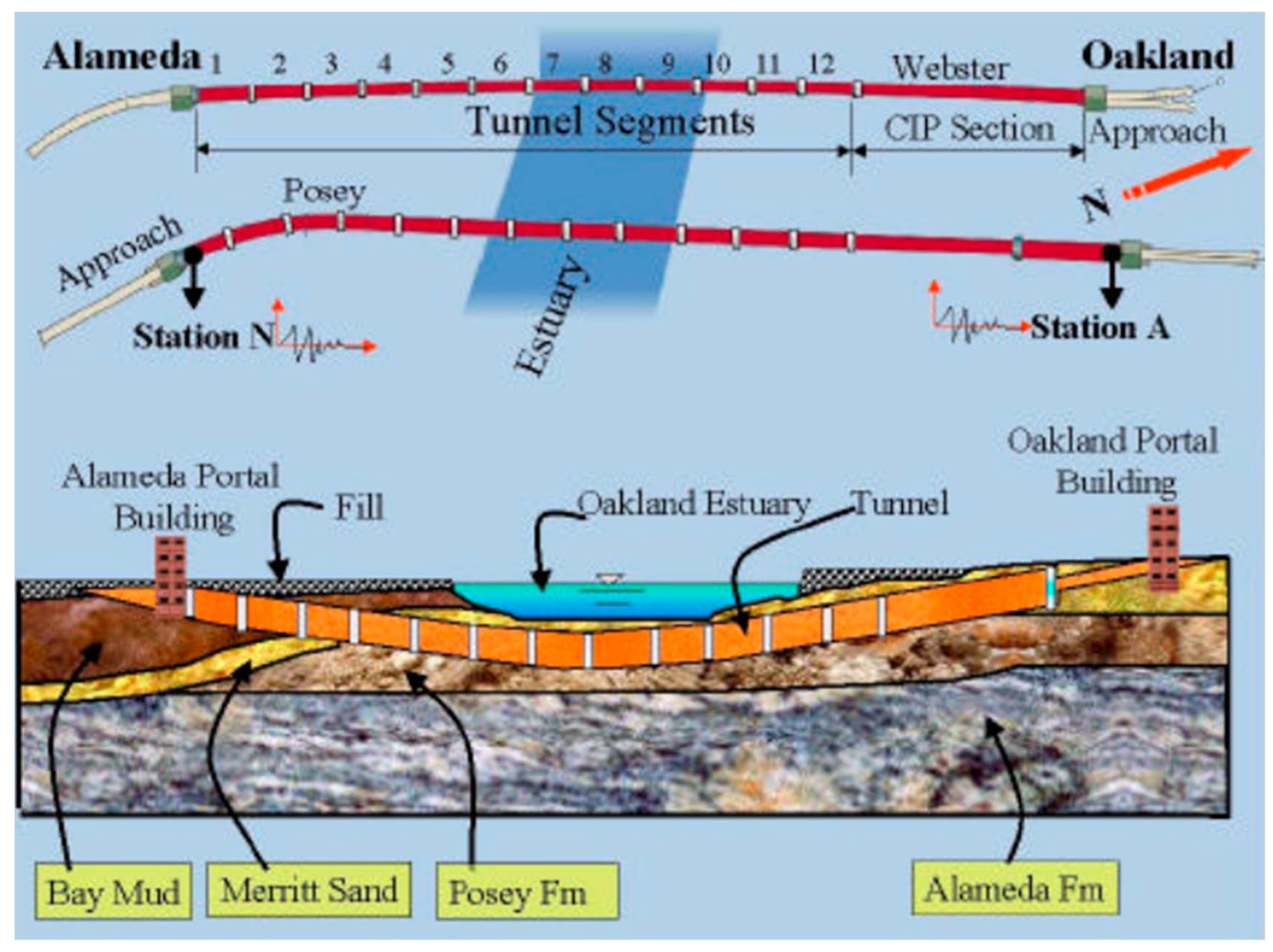
Following placement in a pre-excavated trench at the Bay floor, the joints were sealed with steel and concrete. The sub-tunnel space was filled with loose sand, while the trench backfill was composed of soft clay and loose sand from the Bay. The local subsurface stratigraphy comprises five major layers (Figure 20). Beneath the ground surface, the Alameda Formation - consisting of dense medium to coarse gravelly sand interbedded with sandy silt to clayey silt -overlies bedrock at about 180 m depth. Above this lies the Posey Formation, composed of stiff to very stiff sandy silt to clayey silt, followed by very dense Merritt sand, and capped by soft Bay mud.
Seismically, the site lies approximately 22 km from the San Andreas Fault and only 6 km from the Hayward Fault (Figure 19). The Hayward Fault presents the primary seismic hazard, capable of generating a magnitude 7.25 earthquake, with peak horizontal rock accelerations up to 0.76 g and surface ground accelerations exceeding 0.5 g. The anticipated duration of such an event may exceed 45 seconds, allowing significant pore pressure buildup that could induce widespread liquefaction and potential tunnel flotation.
Figure 19.
Location of the Posey and Webster Street Tubes (Google Maps).
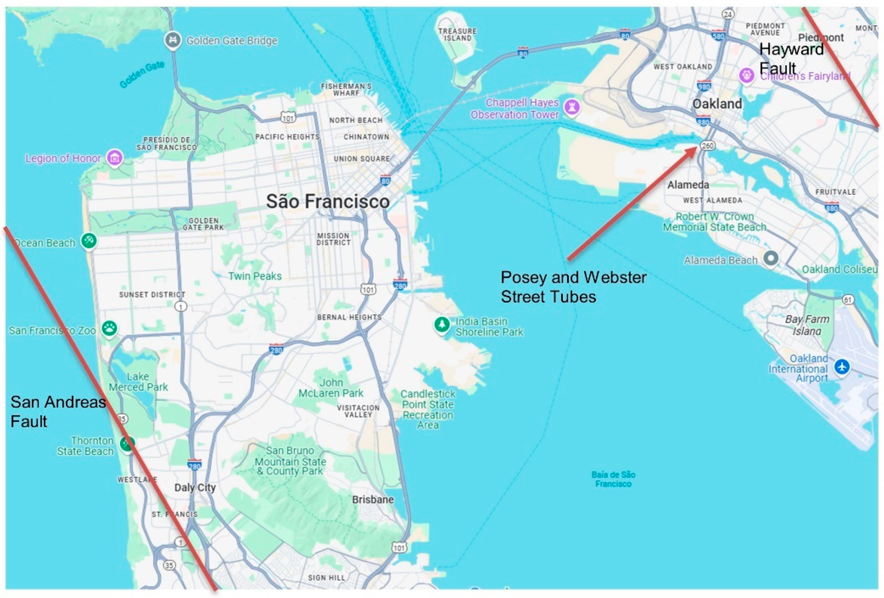
Figure 20.
Stratigraphy of the Posey and Webster Street Tubes site [39].
Figure 20.
Stratigraphy of the Posey and Webster Street Tubes site [39].
The most recent major seismic event impacting the area was the 1989 Loma Prieta earthquake. This event caused liquefaction in Alameda and in the vicinity of the tunnels. In response, a seismic retrofit plan was implemented in 1997. The retrofit strategy focused on mitigating flotation risk and improving structural performance through ground improvement of the backfill and structural upgrades, respectively.
Ground improvement measures included the installation of stone columns on both sides of the Webster Street Tube to densify the backfill and facilitate pore pressure dissipation during seismic events. Jet grouting was applied adjacent to the Posey Street Tube to laterally isolate it from the backfill. Structural retrofits included the modification of existing full-perimeter joints between tunnel elements to accommodate expansion, and the addition of special joints at the connections to the portal buildings. These modifications were aimed at improving flexibility, reducing internal forces, and maintaining watertightness during seismic loading.
As part of the retrofit project, Kozak et al. [40] conducted advanced nonlinear finite element analyses to assess soil-structure interaction effects under earthquake loading. Their models incorporated wave passage, scattering, and reflection phenomena. The use of detailed three-dimensional global models, including nonlinear material behaviour and realistic boundary conditions, provided critical insights into tunnel response under strong ground motion. These global models were supplemented with two-dimensional local analyses for evaluating ultimate load capacity due to racking effects. A specialized three-dimensional model was also developed for the Posey Tube’s transition element, and subjected to racking, to investigate the impact of geometric changes under seismic loading.
In the global 3D finite element model, the tunnels were represented with beam and truss elements, while nonlinear springs were used to simulate soil behaviour. Seismic excitations were applied as displacement time histories at the soil boundaries. A comparative analysis was conducted for both the original and retrofitted tunnel configurations. In the retrofitted model, inter-element joints were modified to eliminate tensile force transmission, significantly reducing axial forces, shear forces, and bending moments to within acceptable limits.
Parametric studies explored the effects of varying soil spring spacing, torsional spring stiffness, and element length on tunnel response. It was concluded that modelling soil springs at 15 m intervals, with at least two finite elements between them, provided a reliable approximation of seismic response. The results demonstrated that the proposed retrofit measures significantly improved tunnel performance, particularly in reducing joint displacements. Furthermore, the analyses underscored the importance of modelling the nonlinear behaviour of surrounding soils when assessing tunnel deformation and joint responses.
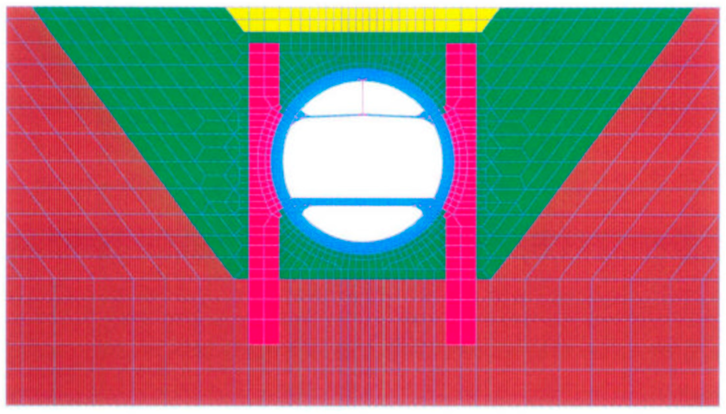
A separate two-dimensional racking analysis of the Posey Tube was also carried out, incorporating site stratigraphy, backfill, jet grout, tunnel walls, slabs, and reinforcement (Figure 21). The construction sequence of the immersed tunnel was included in the model. A racking displacement of 0.10 m was applied incrementally using inelastic static analysis. Outputs included stress distributions in soil and tunnel, reinforcement bar stresses, and crack development in walls and slabs. These results helped identify critical shear zones at the backfill/soil interface, and at the walls of the tunnel, and provided further validation of the jet grout’s effectiveness in enhancing soil-structure performance.
Finally, the specialized three-dimensional model for the transition element of the Posey Tube was subjected to a 0.30 m racking displacement using linear elastic incremental static analysis. The results revealed that stress concentrations diminished rapidly beyond the transition zone, suggesting that abrupt geometric changes primarily affected localized tunnel behaviour.
Figure 21.
Finite element mesh for the racking analysis of the Posey Tube [39].
Figure 21.
Finite element mesh for the racking analysis of the Posey Tube [39].
5.3. The Waihuan Tunnel
The Waihuan Tunnel is a 2888 m-long bi-directional immersed tunnel beneath the Huangpu River in Shanghai, China [41]. It features a large cross-section (43 m × 9.55 m) accommodating eight traffic lanes (Figure 22) and consists of seven immersed elements, each 100-108 m in length, connected by eight flexible joints (Figure 23).
Ding et al. [41] developed a large-scale numerical simulation method to assess the seismic response of the tunnel, employing a three-dimensional dynamic finite element model executed on a high-performance computing system. The analysis used LS-DYNA, a general-purpose finite element code capable of modelling dynamic large-deformation structural responses. The finite element mesh included four-node tetrahedral elements for the surrounding soil, eight-node hexahedral solid elements for the tunnel structure, and beam elements to represent prestressed cables. The model boundaries were placed at a distance exceeding four times the tunnel’s cross-sectional width to minimize boundary effects (Figure 24).
The site’s subsurface conditions comprise multiple layers of cohesive silts and clays. Their mechanical behaviour was modelled using an elastoplastic constitutive relation based on the Drucker-Prager yield criterion. The tunnel’s flexible joints include Gina gaskets and vibration isolation bearings, both composed of rubber exhibiting nonlinear geometric and material behaviour (Figure 25). The rubber components were modelled using the Mooney-Rivlin hyperelastic formulation [42]. The steel shear key was simulated with a constitutive model incorporating isotropic and kinematic hardening plasticity, as well as strain-rate effects.
Seismic input was based on ground motions from the 1976 Tangshan earthquake (magnitude 7.6), applied independently in the longitudinal and transverse directions at the bedrock level. The vertical and orthogonal displacements were constrained accordingly. The peak ground acceleration (PGA) at the tunnel site was approximately 0.1 g. To prevent spurious reflections at the model boundaries, normal viscous boundary conditions were applied. The dynamic analysis employed an explicit time integration scheme with a parallel domain decomposition algorithm [43].
The analysis revealed that the largest relative displacements between adjacent tunnel elements occurred at the tunnel extremities, with a maximum value of 0.024 m. Gina gaskets experienced compressive deformations ranging from 0.005 m to 0.023 m, while the vibration isolation bearings atop the shear keys displaced between 0.004 m and 0.007 m. The results confirmed that the incorporation of eight flexible joints effectively reduced stress concentrations along the tunnel walls and enhanced the overall seismic resilience of the structure. Consequently, flexible joints play a critical role in the earthquake-resistant design of immersed tunnels, preventing unacceptable deformation. Their performance depends on the behaviour of internal components such as Gina gaskets and shear keys made of steel and concrete.
5.4. The George Massey Tunnel
The George Massey Tunnel, completed in 1959, connects Vancouver, British Columbia, Canada, with Washington State, USA. The tunnel spans 1.3 km beneath the Fraser River, comprising a 370 m north approach, a 629 m immersed section, and a 335 m south approach (Figure 26). The immersed portion includes two traffic shafts, each carrying two lanes, and two external ventilation ducts (Figure 27). Tunnel elements were precast in 105 m segments within a graving dock, floated into position, and submerged into a shallow trench on the riverbed. After placement, sand was jetted to fill the space beneath the tunnel, and gravel and rockfill were placed around and above the structure to ensure stability against buoyancy and to protect against scour [44].
The geological profile, derived from borehole data, is shown in Figure 28 (approximately 50 m deep and 1000 m wide). The upper 15 m of subsoil consists of loose sand and interbedded sandy silt, underlain by clayey silt [45].
Figure 26.
The George Massey Tunnel location (reproduced with permission from [46] and COWI).
Figure 26.
The George Massey Tunnel location (reproduced with permission from [46] and COWI).
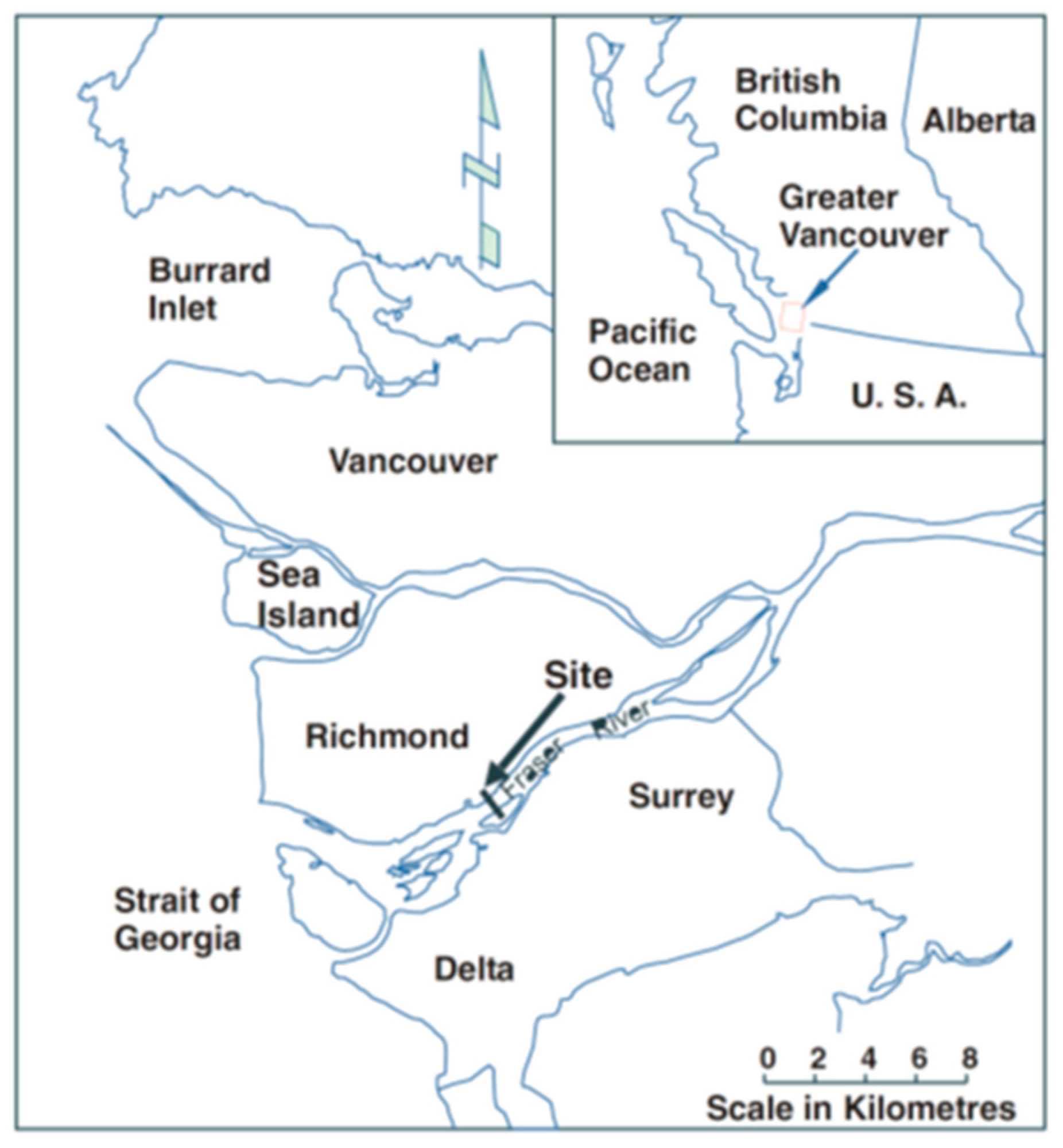
Figure 27.
The George Massey Tunnel cross-section (reproduced with permission from [46] and COWI).
Figure 27.
The George Massey Tunnel cross-section (reproduced with permission from [46] and COWI).
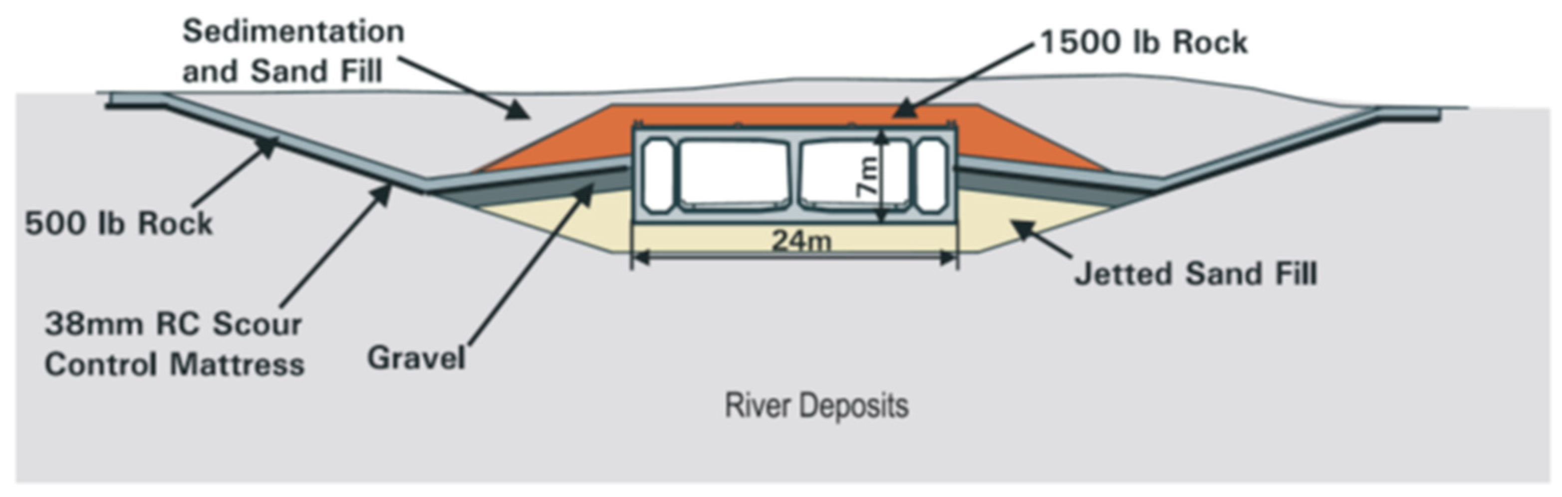
Figure 28.
Geological profile along the George Massey Tunnel (reproduced with permission from [46] and COWI).
Figure 28.
Geological profile along the George Massey Tunnel (reproduced with permission from [46] and COWI).
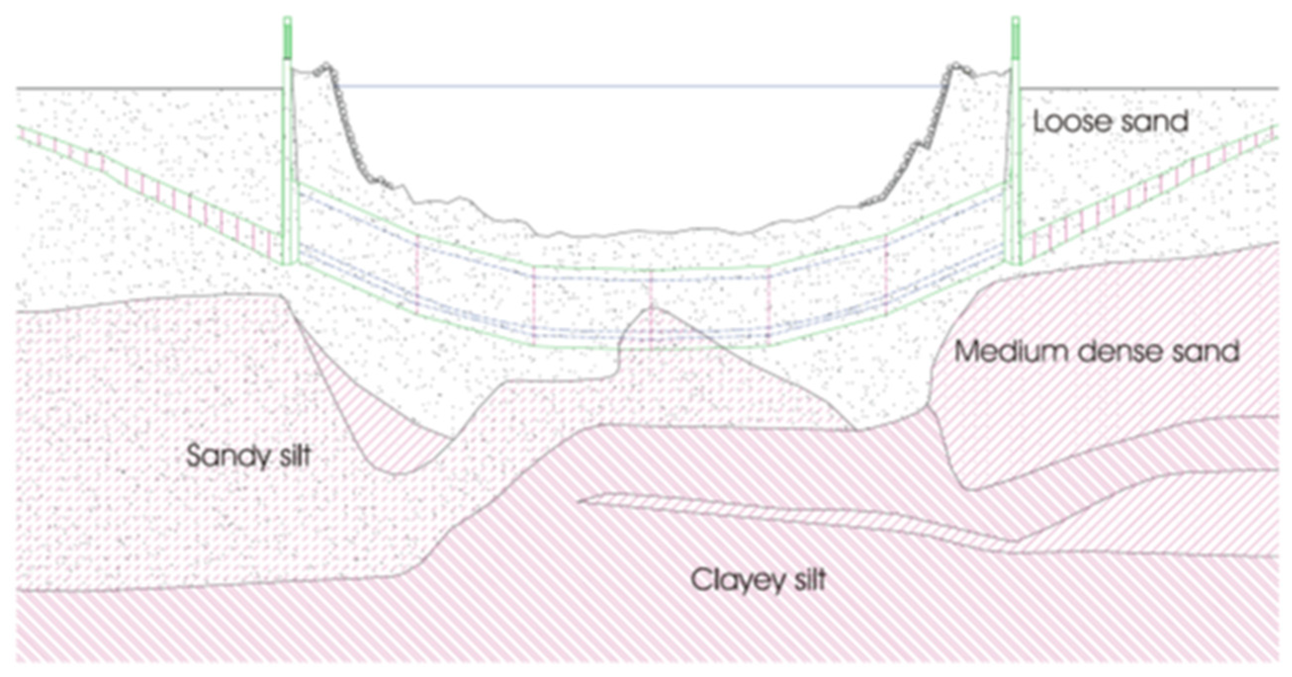
In 2003, the tunnel underwent seismic retrofitting to resist two design earthquake scenarios: (1) a local non-subduction event with PGA of 0.25 g and moment magnitude (Mw) 7.0, and (2) a distant subduction earthquake with PGA of 0.15 g and Mw 8.2. The retrofit aimed to prevent collapse and loss of life while limiting damage to repairable levels, including controllable water ingress [44,45]. The primary challenge was addressing potential soil liquefaction in both the native loose deposits and the jetted backfill sand and its consequences.
Design earthquake motions were specified at the bedrock outcrop, approximately 300 m below the site. Ground response analyses using the equivalent-linear method [47] provided input motion time histories at 50 m depth and cyclic stress ratios for preliminary liquefaction triggering assessments.
The primary geotechnical design tool was two-dimensional nonlinear dynamic analysis using FLAC. Constitutive models included UBCTOT and UBCSAND, developed at the University of British Columbia [38,48,49], addressing dynamic loading, liquefaction initiation, post-liquefaction behaviour, and soil-structure interaction. Model parameters were calibrated using laboratory and empirical data. During shaking, pore pressures were generated via shear-induced plastic volumetric strain, reducing mean effective stress and initiating water flow gradients.
Both transverse and longitudinal sections were modelled. Transverse models assessed liquefaction effects around the tunnel, riverbed morphology influence, and pore pressure redistribution, helping to optimize mitigation strategies. The longitudinal model evaluated "migration effects," wherein liquefied soils beneath the tunnel and riverbanks could flow toward the mid-river, driven by stress gradients (higher stresses at the riverbanks). This would induce settlement beneath the banks and uplift of the tunnel in the channel. Due to consolidation of the liquefied soils during the post-liquefaction phase, tensile forces could develop at the tunnel ends and compression forces in mid-sections, with potential for excessive bending moments in the tunnel [45].
Analyses included various earthquake records, riverbed slopes, and soil profiles [44]. Key tunnel vulnerabilities identified were:
- Wave passage effects: The tunnel’s length leads to varying seismic motion along its alignment. Propagating waves induce stresses in the tunnel, exacerbated by heterogeneity in soil conditions.
- Liquefaction (up to 20 m depth): A critical factor, more influential than wave passage effects. Liquefaction reduces soil stiffness and strength, leading to ground failure and differential movement. Consequences include tunnel uplift, lateral displacement due to riverbed slope, movement of soil from the river banks toward the centre channel, upward heave of the approach structures, and differential consolidation settlement after shaking due to post-liquefaction dissipation of excess pore water pressures.
- Groundwater migration: Elevated pore pressures during shaking can cause vertical water flow or lateral flow under the tunnel or approach structures, inducing uplift. Low-permeability interlayers may direct excess pore pressure to dissipate toward the tunnel post-earthquake and induce uplift [45].
- Stiff joints between the tunnel and ventilation structures: These may attract significant tensile/compressive forces, risking joint failure.
Wave passage in rock (velocity = 2000 m/s) induced displacements <0.05 m over 650 m. Soil column variations in the upper 50 m added ~0.02 m differential settlement. However, liquefaction-induced movements were an order of magnitude greater and dominated the design. With a flat riverbed and no ground improvement, the tunnel could heave 0.5-1.5 m during shaking. A sloped riverbed reduced vertical heave to 0.2-0.3 m but led to lateral displacements of 1-2 m [44].
These effects could result in cracking, especially in under-reinforced areas and joints, potentially causing water leakage. Thus, the retrofit objective was to avoid structural failure and restrict damage to ensure reparability after a major earthquake [46]. As significant uplift and lateral tunnel displacements were expected, various deformation mitigation strategies were evaluated, including ground densification, gravel drains, sheet piles to stop liquefied soil and water from moving in under the tunnel, jet grouting to support the tunnel and prevent soil movement under the tunnel, and compaction grouting and micropiles to control post-liquefaction settlement. Widths and configurations of densification zones were optimized through modelling.
A final structural retrofit was developed using a 3D ABAQUS finite element model of the tunnel and ventilation buildings, incorporating soil-structure interaction. Equivalent springs represented surrounding soil stiffness. Two critical loading scenarios were considered: (a) seismic loading from wave passage; and (b) post-liquefaction differential settlement based on 2D longitudinal analyses. UBCSAND was found to underestimate post-liquefaction consolidation, necessitating a bulk modulus adjustment to achieve realistic settlements.
Sheet piles effectively reduced uplift but were less efficient for lateral restraint on sloped beds and were costlier than alternative solutions. Similarly, jet grouting cut-off walls were more expensive than stone column densification.
Therefore, the selected measures included ground densification through vibro-replacement stone columns and vertical seismic drains on both sides of the tunnel (Figure 29). The former controlled uplift and lateral spread; the latter dissipated excess pore pressure and prevented groundwater-induced uplift. Gravel drains also reduced pore pressure buildup in the densified zones, maintaining soil strength during shaking.
Numerical analysis predicted that, with these measures, lateral tunnel displacement would be limited to 0.1-0.4 m, vertical heave to <0.2 m, and differential settlement, due to post-liquefaction consolidation, to <0.6 m over 250 m [44].
Finally, centrifuge testing [26] was conducted to validate numerical predictions. Three tests were performed: (1) no ground improvement, (2) 10 m densification zones, and (3) 10 m gravel drainage zones, on either side of the tunnel. Results confirmed liquefaction under design earthquakes and associated upward and lateral tunnel movements. Both improvement strategies reduced displacements, with gravel drains showing greater effectiveness per unit area treated. Overall, good agreement between centrifuge test and numerical model results supported the final retrofit decision [50].
5.5. The Hong Kong-Zhuhai-Macau Immersed Tunnel
The Hong Kong-Zhuhai-Macau (HZM) Bridge spans approximately 35.6 km across the Pearl River Estuary, connecting the cities of Hong Kong, Zhuhai, and Macau. The primary crossing comprises two artificial islands and a 5.7 km long immersed tunnel (Figure 30), reaching a maximum depth of 45 m. The tunnel consists of 33 prefabricated reinforced concrete elements, each 180 m long and composed of eight 22.5 m segments. The tunnel cross-section is nearly rectangular, with a width of 37.95 m and a height of 11.4 m, containing three separate cells: two for vehicular traffic and one for pipelines and ventilation.
Most elements rest on approximately 60 m thick, soft soil layers composed of muck, mucky soil, silty clay, mealy sand, medium sand, and coarse sand, with significant variability across layers (Figure 31). The segment joints incorporate omega seals, injectable rubber-metal gaskets, reinforced concrete shear keys, and prestressed cables (Figure 32). These joints lack continuous reinforcement, allowing articulation during settlement, while shear keys constrain vertical and horizontal displacements. Due to the site-specific ground conditions, the temporary prestressed cables are retained in the HZM Tunnel.
Figure 30.
Location of the HZM Tunnel (Google Maps).
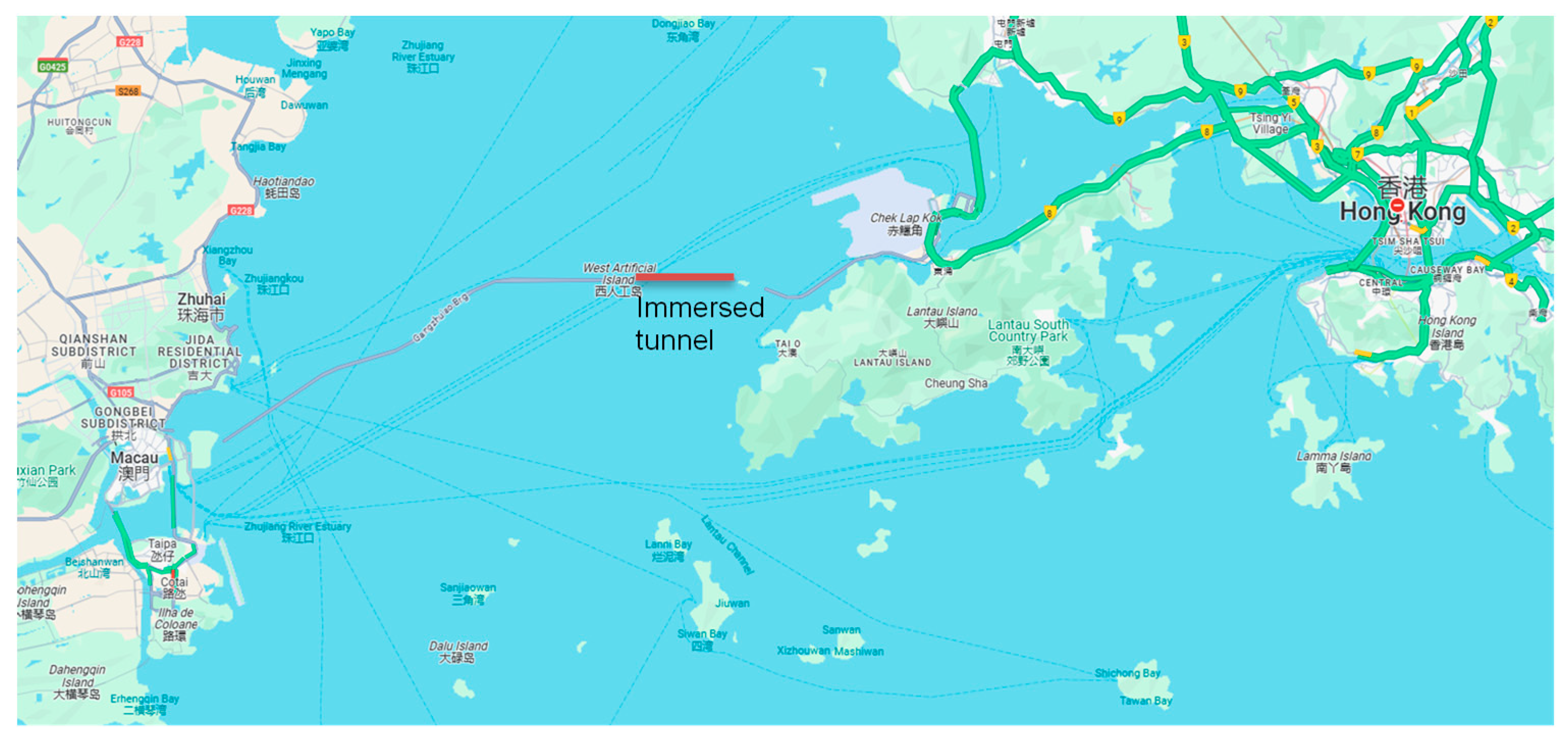
Figure 31.
Geological profile and foundation conditions of the HZM Tunnel (reproduced with permission from Hu et al. [51]).
Figure 31.
Geological profile and foundation conditions of the HZM Tunnel (reproduced with permission from Hu et al. [51]).
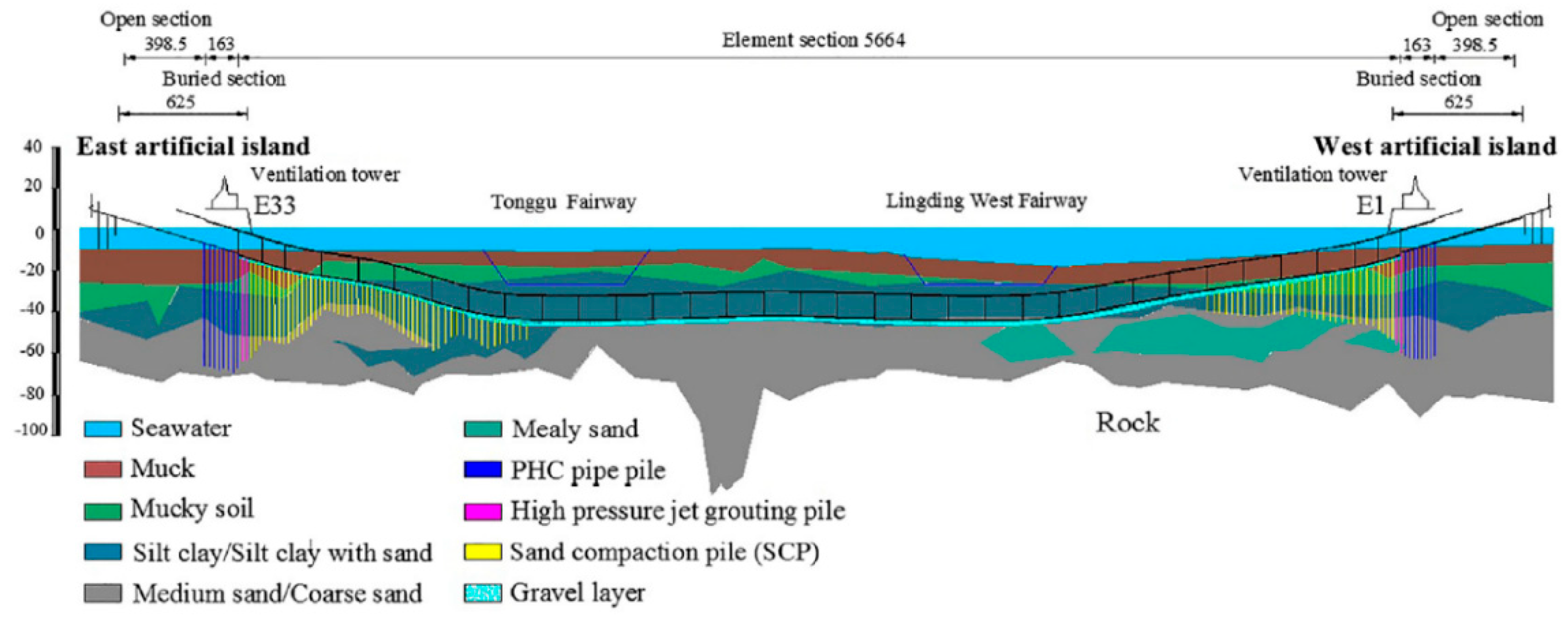
Figure 32.
Cross-section of segment joints of the HZM Tunnel (m) (reproduced with permission from Hu et al. [51]).
Figure 32.
Cross-section of segment joints of the HZM Tunnel (m) (reproduced with permission from Hu et al. [51]).
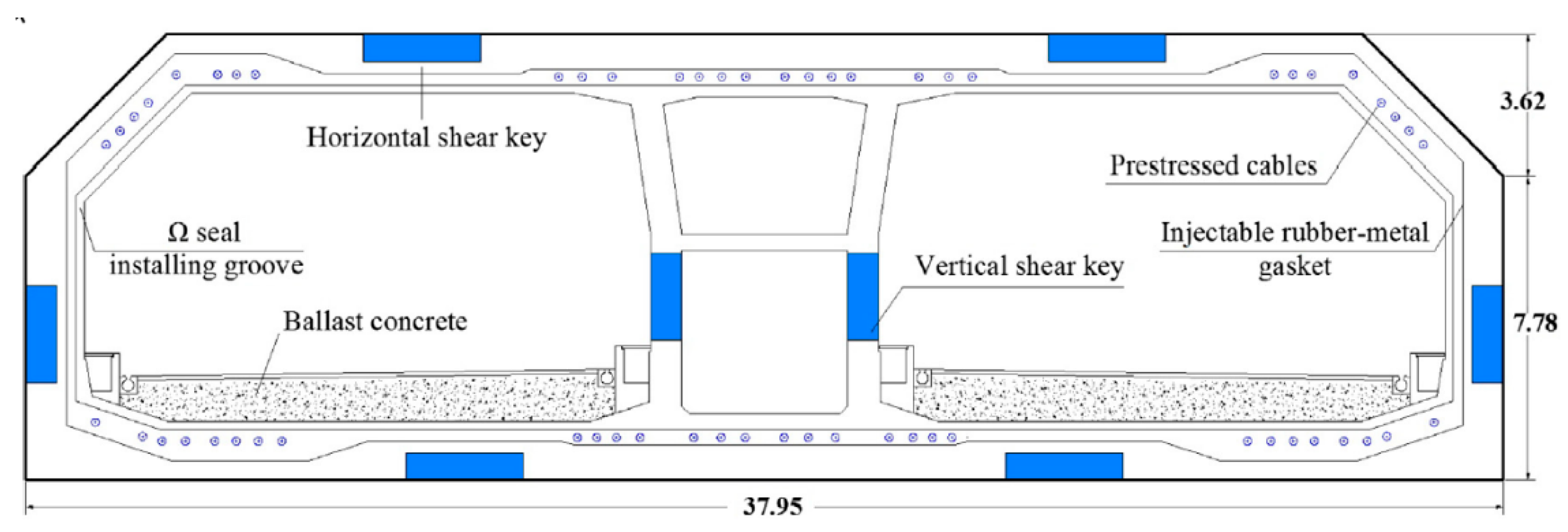
Li et al. [52] developed a simplified numerical model to analyse the seismic response of the tunnel under longitudinally non-uniform earthquake excitation, accounting for wave passage effects and local site conditions. A 1D linear analysis was used to determine the free-field motion, and a mass-spring-dashpot model was adopted for the tunnel-ground system. The surrounding ground was discretized into slices perpendicular to the tunnel axis, each modelled as a mass connected to the bedrock and adjacent masses via springs and dashpots. Tunnel-ground interaction was also represented by springs and dashpots connecting each ground mass to the tunnel, which was modelled as a beam system (Figure 33). Immersion joints were represented by five nonlinear springs capturing longitudinal displacement, transverse and vertical bending (Gina gaskets), and transverse and vertical shear (steel shear keys). The results showed that non-uniform excitation significantly increased joint deformation, especially at lower wave velocities due to larger time lags and intensified non-uniformity.
Chen et al. [53] conducted dynamic finite element analyses to further investigate the effects of ground spatial variability and wave passage. First, a 2D free-field model (without the tunnel) was used to obtain ground acceleration time histories beneath the tunnel. The wave passage effect was found to reduce peak ground acceleration (PGA), whereas ground variability increased it. Low-frequency amplification was observed, notably when ground properties varied spatially. Subsequently, a 3D beam-spring-dashpot model of the tunnel was developed (Figure 34), where each tunnel segment was divided into four beam elements and joints were modelled using nonlinear springs with five degrees of freedom (axial compression, horizontal and vertical shear, horizontal and vertical bending). Prestressed cables in the segment joints were simulated using tension-only truss elements. The results revealed that both wave passage and ground spatial variability substantially increased axial forces and Gina gasket deformations, while the latter also caused elevated bending moments. When both effects were combined, gasket deformations exceeded design compression limits, indicating a risk of joint failure and leakage.
Yan et al. [54] and Yuan et al. [55] designed a linear multi-point shaking table system and a 40 m long segmented model container to simulate the tunnel’s seismic response under non-uniform excitation. A 1:60 scale tunnel model rested on four shaking tables capable of motion in multiple directions and rotation in the horizontal plane. Time lags between tables simulated wave passage effects. The in-situ soil, mainly fine silty sand, was represented by a synthetic mixture of sawdust and sand (mass ratio 1:2.5), achieving similar dynamic properties. Gina gaskets were represented by silicone strips, and steel cables were used to simulate prestressed connections between segments.
Yu et al. [56] tested the scaled model under various seismic amplitudes. Results showed that non-uniform excitation caused greater joint deformation than uniform excitation. The tunnel exhibited a stronger dynamic response than the surrounding soil, and significant variability was observed across different ground conditions.
Binder et al. [57] performed 44 earthquake tests on 13 model tunnel elements, simulating three epicentre locations and subjecting the structure to P-waves, S-waves, and their combinations. Two embedment scenarios were studied: a thin sediment layer (immediately post-construction) and a thick layer (several years post-construction) covering the tunnel. Frequency analysis yielded the following key insights:
- The tunnel’s first eigenfrequency was approximately 20 Hz in the model, corresponding to 1.15 Hz at full scale.
- Frequencies between 10-20 Hz (0.58-1.15 Hz full scale) were amplified, while those from 30-100 Hz (1.73-5.77 Hz) were attenuated.
- Amplification was greater with a thin overburden, indicating that increased sediment coverage reduces amplification.
- Attenuation was more significant for longitudinal (P-wave) excitation than for transverse (S-wave), suggesting greater tunnel sensitivity to S-waves.
To improve seismic performance of the tunnel joints, Yu et al. [58] proposed the use of Buckling Restrained Braces (BRBs) installed axially between adjacent tunnel elements (Figure 35). The elastic stiffness and yielding force of the device were optimized to maximize energy dissipation. A 1:10 scale model of an immersion joint and two adjacent tunnel elements was tested under compression and cyclic bending. The joint with BRBs dissipated 69% more energy, supported 37% greater bending moments, and exhibited 45% higher flexural stiffness than the unreinforced joint. However, the stiff rubber seal bore a large portion of the bending moment, limiting BRB performance. A softer seal and hinged end connections were recommended to enhance joint rotation and BRB efficiency, by elongating its yielding stage and reducing the bending moment in the device.
Lin et al. [59] developed special vertical shear key bearings designed to "remember" the allowable shear force. Just before exceeding this threshold, the bearings compress to prevent damage in the shear keys, by inducing a vertical offset in the joint, protecting the structure of the immersed tunnel from differential settlement.
Hu et al. [60] examined the mechanical behaviour of segment joints using a 1:4.69 large-scale model tested on a settlement platform. Shear force distribution was found to be mainly governed by the transverse stiffness of the segments. Based on observed failure modes - particularly the zones at the connecting and terminal corners of vertical shear keys where cracking occurred - reinforcement strategies were proposed for those vulnerable areas.
Lastly, Li et al. [61] introduced a hybrid fibre-reinforced concrete (HFRC), combining steel and basalt fibres to enhance the seismic performance of shear keys. A cyclic loading test on fifteen 1:5 scale shear key specimens evaluated different material parameters. An analytical model was also developed to predict the ultimate load-carrying capacity of the shear keys by regression based on the test results. The HFRC improved shear key performance in terms of strength, ductility, and energy dissipation, outperforming conventional concrete. Fibers bridged cracks and delayed propagation, with fibre reinforcement proving more effective than increased rebar ratios for enhancing seismic resilience.
5.6. The Future Tagus River Crossing Case-Study
A third Tagus River crossing is currently under consideration downstream of the 25 de Abril Bridge in Lisbon, Portugal, between Algés and Trafaria (Figure 36), prompted by increasing traffic demand on the existing bridge. This new infrastructure would connect Highway A33 on the southern bank to IC17-CRIL on the northern bank and is situated along the only viable road corridor, as determined through geographic, environmental, economic, technical, and construction feasibility assessments. The central tunnel alternative (Figure 36) involves the construction of an immersed tunnel approximately 2.4 km in length.
The river reaches a maximum depth of approximately 30 m in the proposed area. The immersed tunnel would be founded on the alluvial sands of the Tagus River, which reach a maximum thickness of about 50 m and overlie Miocenic deposits of increasing stiffness and strength with depth, and a basalt bedrock (Figure 37).
Tagus river sands are predominantly siliceous, clean, and poorly graded, classified as SP under the Unified Soil Classification System. Standard Penetration Test (SPT) data were primarily obtained from boreholes along the northern riverbank, between Algés and Cruz Quebrada, and from the landfill area near the maritime traffic tower in Algés. In the Algés-Cruz Quebrada section, SPT N-values ranged from approximately 11 in the upper 5 m, to 20 between 5 and 14 m depth, and 30 between 14 and 25 m. In the maritime traffic tower landfill, the sands at depths between 6 and 10 m had an average N-value of 17. Due to the low flow velocities near the riverbed at the tunnel alignment, similar SPT values were assumed for the central channel.
Figure 37.
Third Tagus River crossing geologic profile: a - alluvial Tagus River sands; b - volcanic Lisbon complex; C - Cretacic unit; M - Miocenic unit [62].
Figure 37.
Third Tagus River crossing geologic profile: a - alluvial Tagus River sands; b - volcanic Lisbon complex; C - Cretacic unit; M - Miocenic unit [62].
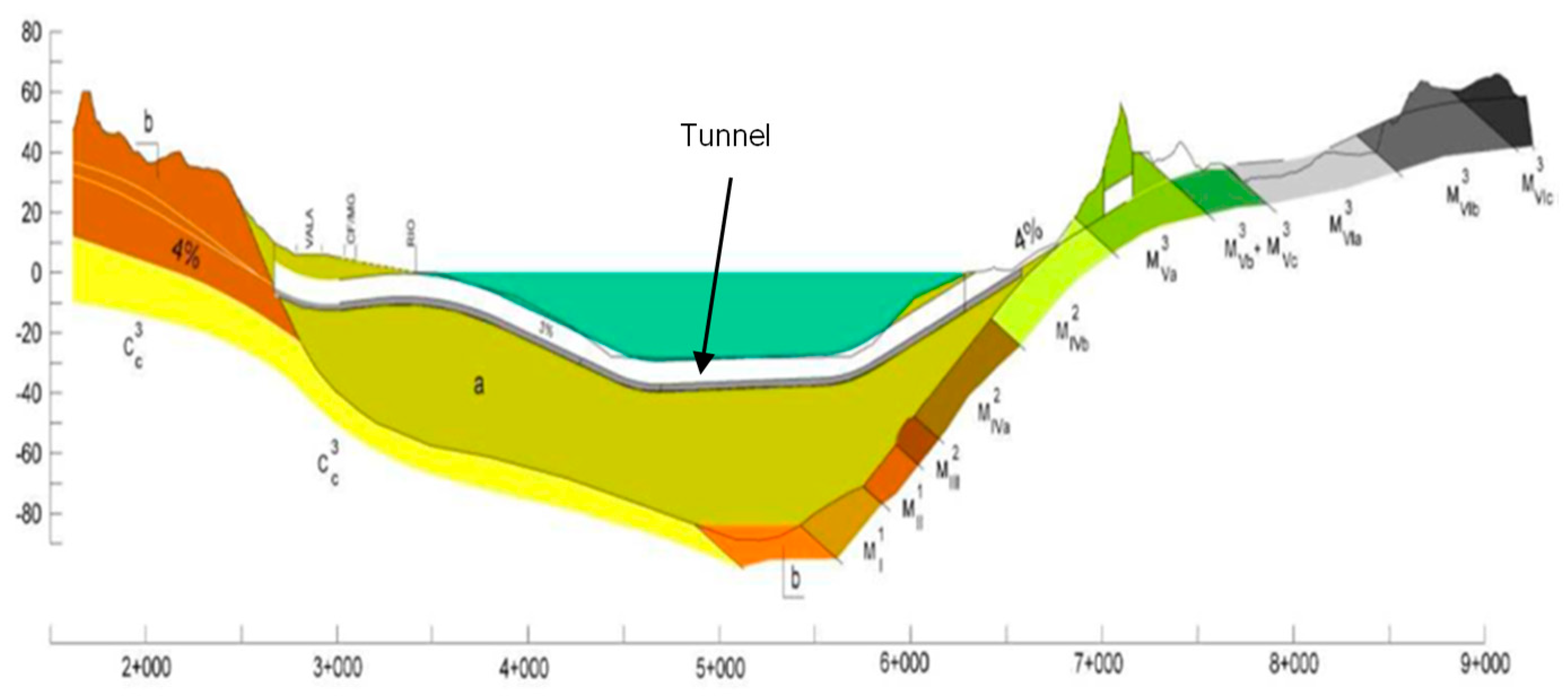
The tunnel cross-section was preliminarily designed as a rectangular reinforced concrete section approximately 40 m wide and 11 m high (Figure 38). It includes two main cells accommodating three traffic lanes in each direction - one of which may be allocated for light rail transit - and a central cell designated for pedestrian evacuation, a cycling route, and service installations. Given the tunnel’s length of under 4 km, a longitudinal ventilation system, combined with a semi-transverse exhaust system for fire events, is deemed sufficient.
Both the roof and base slabs are designed with a thickness of approximately 1.50 m, corresponding to a span-to-thickness ratio of roughly 10:1. For simplicity and constructability, the roof and base slabs share the same thickness (Figure 38). These dimensions are based on precedents from immersed tunnels constructed under similar hydrostatic pressures (approximately 30 m water head). The permanent uplift condition was assessed in the final construction stage, requiring a ballast layer of 1 m to ensure stability. Floatation during transportation was also verified under the worst-case buoyancy conditions.
A segmental construction approach is proposed, using the full-section casting method to pour each segment monolithically, thereby avoiding early-age cracking and eliminating the need for construction joints. Thus, a waterproofing membrane is not considered necessary. Temporary prestressing between segments will be retained in service to enhance seismic performance. Discrete shear keys will be integrated into the walls and slabs of the tunnel at both immersion and segment joints. Each joint between tunnel elements will include a dedicated seismic immersion joint designed to accommodate differential movements.
In terms of earthworks, the bottom of the trench will be excavated to a width 6 m greater than the external width of the tunnel. A side slope of 1:3 is proposed for the underwater excavation to ensure slope stability in sandy soils and to minimize riverbed material scour. The foundation layer will consist of 1.50 m of gravel fill, chosen for its favourable seismic performance characteristics. Over the tunnel, a 1.50 m rockfill protection layer will be placed, containing the gravel locking and engineered backfill. The locking fill will extend horizontally 3 m from the tunnel wall and then with a 1:2 slope. The general backfill will comprise the dredged riverbed material. A scour protection layer is not included above the general backfill, as no significant bed changes are anticipated.
Figure 38.
Simplified immersed tunnel cross-section and planned application of an expansive polyurethane resin liquefaction mitigation measure.
Figure 38.
Simplified immersed tunnel cross-section and planned application of an expansive polyurethane resin liquefaction mitigation measure.
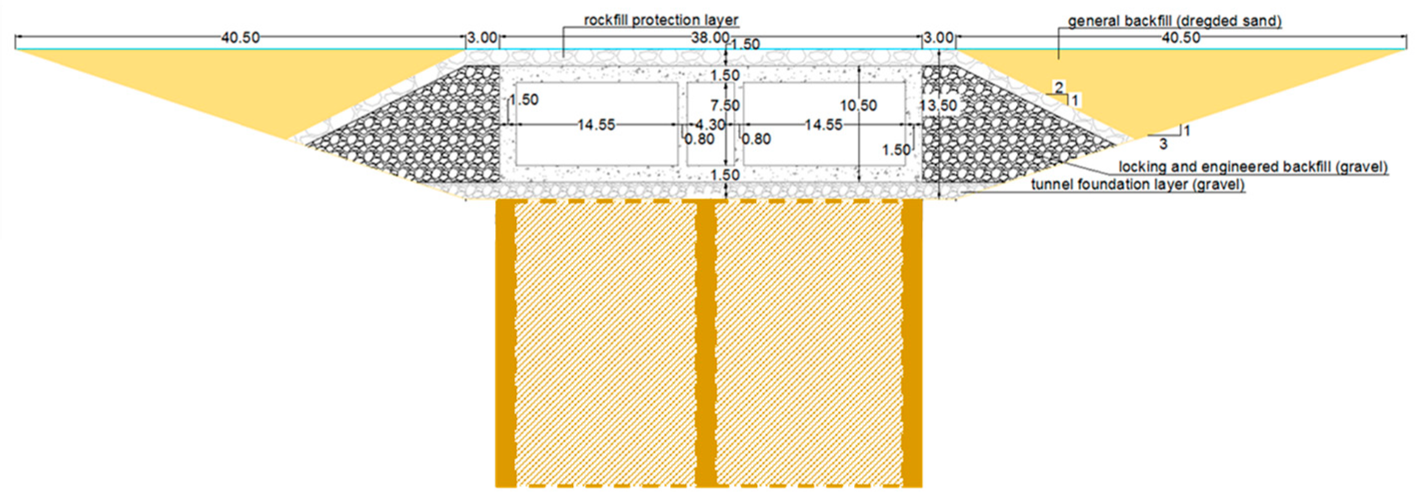
To mitigate the risk of liquefaction, a ground improvement system involving longitudinal polyurethane resin “panels” is proposed. Two panels would be installed beneath the exterior walls of the tunnel, with an additional central panel along the tunnel’s longitudinal axis due to its large width (Figure 38). At immersion joints and other critical transverse sections, connecting transverse resin panels would be implemented, providing additional stiffness and forming a grid that densifies the surrounding soil, restricts liquefied sand migration beneath the tunnel, and enhances seismic support.
5.7. Analysis and Discussion
Table 1 summarizes the key characteristics of the selected immersed tunnel projects, including tunnel type and cross-section, element length, foundation ground and backfill materials, joint configurations, and ground improvement measures where applicable.
Most of the tunnels are constructed with reinforced concrete (with the exception of the Transbay Tube, TBT) and feature rectangular cross-sections, except for the Posey and Webster Street Tubes, which have circular profiles. Flexible joints are typically employed to accommodate seismic movements. In the TBT, specially designed terminal joints were implemented to address seismic demands. For the Posey and Webster Street Tubes, the original joints were retrofitted to consider expansion and supplemented with special joints at the interface with portal structures.
Ground improvement measures were implemented in all cases where the foundation soil consisted primarily of sand, aiming to mitigate the risks of liquefaction, pore water pressure migration, and uplift. No ground improvement was undertaken for the TBT and the Waihuan Tunnel, as their foundation soils were predominantly clayey and less susceptible to such hazards.
Table 2 presents the analysis approaches, critical seismic design phenomena, and the corresponding maximum estimated tunnel displacements. Numerical simulations were applied in all case studies. In addition, centrifuge testing supported the analyses of the TBT and the George Massey Tunnel, while shaking table and joint-specific testing were used in the study of the Hong Kong-Zhuhai-Macau Tunnel.
The predominant design challenge across the projects was tunnel uplift. However, other significant factors were also noted. For the Posey and Webster Street Tubes and the Waihuan Tunnel, longitudinal differential displacements were critical. In the George Massey Tunnel, lateral displacements resulting from liquefaction were significant, along with potential joint failures caused by tensile and compressive forces between the tunnel and associated ventilation structures. In the Hong Kong-Zhuhai-Macau Tunnel, joint failure due to non-uniform seismic loading and spatial variability of ground conditions was a key concern.
The George Massey Tunnel exhibited the largest recorded seismic-induced displacements: a maximum uplift of 1.5 m and lateral displacement of 2.0 m prior to retrofitting. These values were successfully reduced to 0.2 m and 0.4 m, respectively, following retrofitting measures. Additionally, the highest longitudinal differential displacement - 0.6 m over a 250 m length - was also recorded in this tunnel, post-retrofit. These movements were closely associated with liquefaction phenomena, underscoring the critical importance of integrating mitigation measures during the design phase.

Table 2.
Analysis methods, conditioning phenomena for design, tunnel displacements.
| Project | Analysis method | Critical seismic design phenomena | Maximum tunnel displacements |
|---|---|---|---|
| Offshore Transbay Tube | analytical expressions, numerical simulations (2D), centrifuge modelling | uplift (ratcheting mechanism, pore water migration, bottom heave) | maximum uplift: 0.25 m |
| Posey and Webster Street Tubes | numerical simulations (local 2D and global 3D models and for a transition element) | uplift due to liquefaction, longitudinal differential displacement, racking | maximum longitudinal differential displacement: 0.24 m (0.12 m after retrofit); maximum joint opening: 0.21 m (Webster Tube end joint after retrofit). |
| Waihuan Tunnel | numerical simulations (3D) | tunnel relative displacements between elements | maximum relative displacements between adjacent tunnel elements: 0.024 m; Gina gasket deformations up to 0.023 m; maximum vertical displacement of vibration isolation bearings: 0.007 m. |
| George Massey Tunnel | numerical simulations (2D), centrifuge testing | uplift in the channel and settlement beneath the banks and lateral displacements due to liquefaction; tensile forces at the tunnel ends and compression forces in mid-sections due to consolidation of the soil during the post-liquefaction phase; joint failure due to significant tensile/compressive forces between the tunnel and ventilation structures. | maximum tunnel uplift: 1.5 m; maximum lateral displacements: 2 m. After retrofitting: maximum tunnel uplift: 0.2 m; maximum lateral displacements: 0.4 m; maximum differential settlement, due to post-liquefaction consolidation: 0.6 m over 250 m. |
| Hong Kong-Zhuhai-Macau Tunnel | numerical simulations (3D), shaking table tests, specific joint model testing | joint failure due to non-uniform seismic loading and ground spatial variability (gasket deformations exceeding design compression limits and shear keys failure) | maximum tunnel element displacement: 0.05 m; maximum tunnel joint deformation considering uniform/non-uniform excitation: 0.02 m/0.04 m (higher near the tunnel approaches). |
6. Conclusions
This paper examined the seismic behaviour of immersed tunnels, focusing on their dynamic response to ground shaking and ground failure. The most relevant conclusions are summarized below, including the main aspects of seismic design, key findings from numerical and experimental studies, joint performance and suggestions for future research.
Seismic Response and Deformation Mechanisms:
- The dynamic response of immersed tunnels is significantly affected by earthquake characteristics, particularly magnitude and epicentral distance.
- Long tunnels are more susceptible to seismic damage, due to spatial variability in ground motion along their length.
- Body waves, especially P-waves and S-waves, are critical in tunnel design. P-waves induce longitudinal tension and compression, leading to axial strains and joint opening/closure, potentially compromising watertightness. S-waves typically cause the highest bending moments, shear forces, and axial loads.
- Racking deformation in rectangular cross-sections generates substantial shear and bending, namely at wall-slab connections, and must be addressed in design.
-
Key ground failure mechanisms for immersed tunnels include liquefaction, fault displacement, and slope instability:
- i.
- Liquefaction can cause significant rotations or displacements of the tunnel, loss of support, uplift, overstressing, joint leakage, and post-earthquake settlement. It can also trigger submarine landslides. Mitigation measures to prevent the occurrence of liquefaction, by increasing density and shear strength of the soil, and dissipating excess pore water pressure, include stone columns, sand compaction piles, in-situ soil mixing, or newer methods like polyurethane resin injection and colloidal silica grouting.
- ii.
- Fault displacement effects can be mitigated by introducing soft soil buffers and enhancing joint flexibility to accommodate offsets.
- iii.
- Slope instability is particularly relevant near tunnel portals on inclined riverbanks, as well as in submerged slopes.
Seismic Design Considerations:
- The seismic design of immersed tunnels differs fundamentally from that of surface structures. Tunnel performance is displacement-controlled, with ground deformations - particularly differential movement along the tunnel axis - being the primary concern.
- Soil-structure interaction is critical due to the contrast in stiffness between the tunnel and surrounding soils.
- Site-specific amplification and attenuation effects must be evaluated to estimate effective ground motions and corresponding structural strains and internal forces.
- Joints must be designed to withstand both compressive and shear loads induced by horizontal and vertical bending during seismic events.
-
Three primary design methodologies are used:
- i.
- Analytical approaches, based on elastic wave propagation and beam-on-elastic-foundation theory to incorporate soil-structure interaction effects.
- ii.
- Numerical methods, such as finite element and finite difference modelling, capable of capturing spatial variability and soil-structure interaction. Simplified numerical approaches such as mass-spring equivalent models are also often employed.
- iii.
- Physical modelling, including centrifuge and shaking-table tests, used to study tunnel flotation, overlying water layer effects, and joint performance.
Key findings from numerical and experimental studies include:
- Bidirectional seismic inputs result in more severe tunnel responses.
- Longitudinal hydrostatic prestressing and robust end supports mitigate longitudinal sliding.
- Liquefaction mitigation measures (e.g., SCPs and vibro-replacement stone columns) reduce settlement and control uplift and lateral spread, but may amplify bending moments and damage in critical areas, especially under higher seismic intensities. Also, gravel drains dissipate excess pore pressure, prevent groundwater-induced uplift, and reduce pore pressure buildup in densified zones. Uplift can be limited by a thin gravel foundation layer, which restricts soil and water migration.
- Overlying water amplifies seismic waves, and increases transverse strains, particularly near joints, and tensile damage and uneven settlement under strong ground shaking. Amplification is greater with a thin overburden, whereas deeper sediment layers dampen wave effects.
Critical insights into tunnel joint performance were identified, notably:
- Tunnel joints play a pivotal role in seismic resilience. Their performance is governed by internal elements such as Gina gaskets and shear keys.
- Both wave passage and ground spatial variability significantly increase axial loads and gasket deformations; the latter also elevates bending moments.
- Increasing joint gasket thickness and reducing element length minimize tensile and compressive forces in joints during seismic loading.
- Joint flexural stiffness increases nonlinearly with axial load. Under cyclic shear, higher axial force promotes elastic behaviour of Gina gaskets, while lower axial forces increase hysteresis.
- Shear stiffness increases with axial load. In particular, vertical shear stiffness increases with longitudinal compression due to gasket enhanced friction, while friction generated by transverse shear force sharing among horizontal keys gives additional resistance.
- Buckling Energy Dissipation Devices (BEDDs) improve hysteresis, flexural stiffness, and bending capacity, although rubber gaskets remain the primary load-bearing element under bending.
- Thermal effects - particularly cooling - can increase axial tension and joint opening. Retaining prestress cables enhances segment joint sealing but may impair immersion joint performance.
Recommendations for Future Research:
- Enhance constitutive soil models which consider liquefaction to better replicate tunnel-soil interaction under seismic loading.
- Investigate optimal spatial distribution of liquefaction mitigation measures through numerical simulations and physical modelling.
- Develop consistent methodologies for evaluating the performance and selecting the most adequate liquefaction mitigation techniques, based on site-specific conditions.
- Create a detailed three-dimensional finite element model to simulate immersion and segment joint behaviour observed experimentally.
- Optimize the design and performance of Buckling Restrained Braces (BRBs) at immersion joints, focusing on material properties and structural connections, through the combined use of numerical and physical methods.
- Explore alternative joint protection strategies, such as rubber or viscous dampers.
- Assess the potential of expanded polystyrene (EPS) geofoam, as a seismic buffer along tunnel sidewalls, to reduce earthquake-induced loads.
Author Contributions
Conceptualization, L.M.; methodology, L:M. and R.C.G.; resources, L.C. and J.B.S.; writing-original draft preparation, L.M.; writing-review and editing, L.M., L.C., J.B.S. and R.C.G.; funding acquisition, L.C. and J.B.S. All authors have read and agreed to the published version of the manuscript.
Funding
This research was funded by Fundação para a Ciência e Tecnologia (FCT), grant number SFRH/BD/99581/2014.
Data Availability Statement
All data used in this study are available within the paper and the cited references.
Conflicts of Interest
The authors declare no conflicts of interest. The funders had no role in the design of the study; in the collection, analyses, or interpretation of data; in the writing of the manuscript; or in the decision to publish the results.
Abbreviations
The following abbreviations are used in this manuscript:
| SCP | Sand compaction pile |
| TBT | Offshore Transbay Tube |
| BART | Bay Area Rapid Transit |
| FEM | Finite Element Method |
| CAS | Coupled Acoustic-Structure |
| HZM | Hong Kong-Zhuhai-Macau |
| PGA | Peak ground acceleration |
References
- Ingerslev, C. Immersed tunnels state-of-the-art. In Underground Space – the 4th Dimension of Metropolises (Barták, Hrdina, Romancov & Zlámal (eds)). Taylor & Francis Group, London, UK, 2007, pp. 1493-1498.
- Ingerslev, C.; Kyiomya, O. Earthquake Analysis. Tunnelling and Underground Space Technology 1997, 12(2), pp. 157-162.
- Kuesel ,T.R. Earthquake design criteria for subways. Journal of the Structural Division 1969, 95, pp. 1213-1231.
- Lunniss, R.; Baber, J. Immersed tunnels. CRC Press, Taylor & Francis Group: Boca Raton, Florida, 2013.
- St John C.M.; Zahrah T.F. Aseismic design of underground structures. Tunnelling and Underground Space Technology 1987, 2(2), pp. 165-197.
- Hashash Y.M.A.; Hook J.J.; Schmidt B.; I-Chiang Yao J. Seismic design and analysis of underground structures. Tunnelling and Underground Space Technology 2001, 16, pp. 247-293. [CrossRef]
- Anastasopoulos I.; Gerolymos N.; Drosos V.; et al. Behaviour of deep immersed tunnel under combined normal fault rupture deformation and subsequent seismic shaking. Bulletin of Earthquake Engineering 2008, 6, pp. 213-239. [CrossRef]
- Boulanger R.W.; Stewart R.W.; Idriss I.M.; et al. Ground improvement issues for the Posey & Webster St. Tubes seismic retrofit project: lessons from case histories. Davis, California, USA, 1997.
- Kiyomiya O. Earthquake-resistant design features of immersed tunnels in Japan. Tunnelling and Underground Space Technology 1995, 10(4), pp. 463-475. [CrossRef]
- Nam S.H.; Song H.W.; Byun K.J.; Maekawa K. Seismic analysis of underground reinforced concrete structures considering elasto-plastic interface element with thickness. Engineering Structures 2006, 28, pp. 1122-1131. [CrossRef]
- Okamoto S.; Tamura C.; Kato K.; Hamada M. Behaviors of submerged tunnels during earthquakes. In Proceedings of the Fifth World Conference on Earthquake Engineering, Rome, Italy, 1973, Vol. 1, pp. 544-553.
- Vrettos C. Design issues for immersed tunnel foundations in seismic areas. In Proceedings of the 1st Greece-Japan workshop on Seismic Design, Observation, and Retrofit of Foundations. Gazetas, Goto & Tazoh (Eds), Athens, Greece, 2005, pp. 257-266.
- Anastasopoulos I.; Gerolymos N.; Drosos V.; et al. Nonlinear Response of Deep Immersed Tunnel to Strong Seismic Shaking. Journal of Geotechnical and Geoenvironmental Engineering 2007, 133(9), pp. 1067-1090. [CrossRef]
- Zhang S.; Yuan Y.; Li C.; Chen H.; Chen Z. Seismic responses of long segmental immersed tunnel under unfavorable loads combination. Transportation Geotechnics 2021, 30, 100621.
- Oorsouw R.S. Behaviour of Segment Joints in Immersed Tunnels under Seismic Loading. Master’s Thesis, Delft University of Technology, Delft, 2010.
- Zhang G.; Wang P.; Zhao M.; Du X.; Zhao X. Seismic structure-water-sediment-rock interaction model and its application to immersed tunnel analysis under obliquely incident earthquake. Tunnelling and Underground Space Technology 2021, 109, 103758.
- Chen W.; Lin J.; Zheng Y.; Liu C.; Huang L. Seismic response and damage analysis of immersed tunnel considering the seabed-seawater coupling effect. Soil Dynamics and Earthquake Engineering 2024, 184, 108853.
- Chen H.; Li X.; Yan W.; Chen S.; Zhang X. Numerical Simulation Analysis of Immersed Tunnel-Joints-Soil. Lifeline Earthquake Engineering 2016, pp. 508-513.
- Zhou X.; Liang Q.; Zhang Y.; Liu Z.; He Y. Three-Dimensional Nonlinear Seismic Response of Immersed Tunnel in Horizontally Layered Site under Obliquely Incident SV Waves. Shock and Vibration 2019, article ID 3131502. [CrossRef]
- Xiao W.; Yuan Y.; Yu H.; Jing L.; Chen Y. Numerical Analysis of Mechanical Behaviours of Immersion Joint. In Proceedings of the 11th World Congress on Computational Mechanics (WCCM XI), Barcelona, Spain, 2014.
- Lyngs J.H. Model Accuracy in Aseismic Design of Immersed Tunnel. Master’s thesis, Aalborg University, Greece, 2008.
- Koseki J.; Matsuo O.; Tanaka S. Uplift of sewer pipes caused by earthquake-induced liquefaction of surrounding soil. Soils and Foundations 1998, 38, pp. 75-87. [CrossRef]
- Yasuda S.; Kiku H. Uplift of sewage manholes and pipes during the 2004 Niigataken-Chuetsu Earthquake. Soils and Foundations 2006, 46, pp. 885-894. [CrossRef]
- Koseki J.; Matsuo O.; Koga Y. Uplift behaviour of underground structures caused by liquefaction of surrounding soil during earthquake. Soils and Foundations 1997, 37, pp. 97-108.
- Yasuda S.; Nagase H.; Itafuji S.; et al. Shaking table tests on flotation of buried pipes due to liquefaction of backfill sands. In Proceedings of the 5th U.S. Japan Workshop on Earthquake-Resistant Design of Lifeline Facilities and Countermeasures against Soil Liquefaction. U.S. National Center for Earthquake Engineering Research (ed), Buffalo, NY, United States, 1994.
- Adalier K.; Abdoun T.; Dobry R.; Phillips R. George Massey Tunnel seismic retrofit final design – RPI centrifuge test results, 2002.
- Sasaki T.; Tamura K. Prediction of liquefaction-induced uplift displacement of underground structures. In Proceedings of the 36th Joint Meeting US-Japan Panel on Wind and Seismic Effects, 2004, pp. 191-198.
- Chian S.C.; Tokimatsu K.; Asce M.; et al. Soil liquefaction – induced uplift of underground structures : physical and numerical modeling. Journal of Geotechnical and Geoenvironmental Engineering 2014, 140, 1-18. [CrossRef]
- Travasarou T.; Chen W.; Chacko J. Liquefaction-induced uplift of buried structures insights from the study of an immersed railway tunnel. In Proceedings of the 5th International Conference on Earthquake Geotechnical Engineering, Santiago, Chile, 2011.
- Cheng X.; Jing L.; Cui J.; et al. Shaking-Table tests for immersed tunnels at different sites. Shock and Vibration 2017, pp. 1-11. [CrossRef]
- Chen H.; Li X.; Yan W.; Chen S.; Zhang X. Shaking table test of immersed tunnel considering the geological condition. Engineering Geology 2017, 227, pp. 93-107.
- Wang Z.Z.; Jiang L.; Gao Y. Shaking table test of seismic response of immersed tunnels under effect of water. Soil Dynamics and Earthquake Engineering 2019, 116, pp. 436-445.
- Xiao W. Experimental Assessment of the Mechanical Behavior of Immersion Joints and a Seismic Mitigation Method in Immersed Tunnels. PhD thesis, Ghent University, Belgium, 2018.
- Yuan Y.; Luo J.; Yu H. Experimental Study on Vertical Shear Behaviors of an Immersion Joint with Steel Shear Keys. Applied Sciences 2019, 9, 5056. [CrossRef]
- Ingerslev C. Immersed and floating tunnels. Procedia Engineering 2010, 4, pp. 51-59. [CrossRef]
- Dongdong C.; Travasarou T.; Chacko J. Numerical evaluation of liquefaction-induced uplift for an immersed tunnel. In Proceedings of the 14th World Conference on Earthquake Engineering, Beijing, China, 2008, pp. 1-8.
- Chou J.C.; Kutter B.L.; Travasarou T.; Chacko J.M. Centrifuge modeling of seismically induced uplift for the BART Transbay Tube. Journal of Geotechnical and Geoenvironmental Engineering 2010, 137, pp. 754-765. [CrossRef]
- Beaty M.H.; Byrne P.M. Ubcsand constitutive model. Itasca UDM Web Site, 2011, pp. 1-69.
- Shamsabadi A.; Sedarat H.; Kozak A. Seismic soil-tunnel-structure interaction analysis and retrofit of the Posey-Webster street tunnels. In Proocedings of the 2nd UJNR Workshop on Soil-Structure Interaction, Tsukuba, Japan, 2001.
- Kozak A.; Sedarat H.; Krimotat A. Alameda Tubes seismic retrofit studies. Computers & Structures 1999, 72, pp. 233-252. [CrossRef]
- Ding J.H.; Jin X.L.; Guo Y.Z.; Li G.G. Numerical simulation for large-scale seismic response analysis of immersed tunnel. Engineering Structures 2006, 28, pp. 1367-1377. [CrossRef]
- Batra R.C.; Ching H.K. Energy release rates in a constrained epoxy disc with Hookean and Mooney-Rivlin materials. Theoretical and Applied Fracture Mechanics 2002, 38, pp. 165-175. [CrossRef]
- Jin X.L.; Guo Y.Z.; Ding J.H. Three Dimensional Numerical Simulation of Immersed Tunnel Seismic Response Based on Elastic-plastic FEM. Key Engineering Materials 2004, Vols. 274-276, pp. 661-666. [CrossRef]
- Naesgaard E.; Yang D.; Byrne P.; Gohl B. Numerical analyses for the seismic safety retrofit design of the immersed-tube George Massey Tunnel. In Proceedings of the 13th World Conference on Earthquake Engineering, Vancouver, B. C., Canada, 2004.
- Yang D.; Naesgaard E.; Byrne P.M. Nonlinear dynamic soil-structure interaction analyses of immersed George Massey Tunnel. Ground Modification and Seismic Mitigation 2006, ASCE, pp. 403-410.
- Taylor P.R.; Ibrahim H.H.; Yang D. Seismic retrofit of George Massey Tunnel. Earthquake Engineering & Structural Dynamics 2005, 34, pp. 519-542. [CrossRef]
- Idriss I.M.; Sun J.I. SHAKE91, A computer program for conducting equivalent linear seismic response analyses of horizontally layered soil deposits, 1992.
- Beaty M.H.. A synthesized approach for estimating liquefaction-induced displacements of geotechnical structures. PhD thesis, University of British Columbia, Vancouver, Canada, 2001.
- Byrne P.M.; Park S-S; Beaty M.; et al. Numerical modeling of liquefaction and comparison with centrifuge tests. Canadian Geotechnical Journal 2004, 41, pp. 193-211. [CrossRef]
- Yang D.; Naesgaard E.; Byrne P.M.; et al. Numerical model verification and calibration of George Massey Tunnel using centrifuge models. Canadian Geotechnical Journal 2004, 41, pp. 921-942. [CrossRef]
- Hu Z.; Xie Y.; Xu G.; Bin S.; Liu H.; Lai J. Advantages and potential challenges of applying semi-rigid elements in an immersed tunnel: A case study of the Hong Kong-Zhuhai-Macao Bridge. Tunnelling and Underground Space Technology 2018, 79, pp. 143-149.
- Li C.; Yuan J.; Yu H.; Su Q.; Yuan Y. Seismic Response Analysis of Long Immersed Tunnel to Longitudinal Non-uniform Excitation. In Proceedings of the 11th World Congress on Computational Mechanics (WCCM XI), Barcelona, Spain, 2014.
- Chen Z.; Liang S.; He C. Seismic performance of an immersed tunnel considering random soil properties and wave passage effects. Structure and Infrastructure Engineering 2018, 14, 1, pp. 89-103. [CrossRef]
- Yan X.; Yuan J.; Yu H.; Bobet A.; Yuan Y. Multi-point shaking table test design for long tunnels under non-uniform seismic loading. Tunnelling and Underground Space Technology 2016, 59, pp. 114-126.
- Yuan Y.; Yu H.; Li C.; Yan X.; Yuan J. Multi-point shaking table test design for long tunnels subjected to non-uniform seismic loadings – part I: Theory and validation. Soil Dynamics and Earthquake Engineering 2018, 108, pp. 177-186.
- Yu H.; Yuan Y.; Xu G.; Su Q.; Yan X.; Li C. Multi-point shaking table test design for long tunnels subjected to non-uniform seismic loadings – part II: Application to the HZM immersed tunnel. Soil Dynamics and Earthquake Engineering 2018, 108, pp. 187-195.
- Binder E.; Li C.; Mang H.; Yuan Y.; Pichler B. Earthquake testing of the 1:60 scaled immersed tunnel of the Hong Kong-Zhuhai-Macao-Bridge: analysis of frequency spectra from 44 experiments. Materials Today: Proceedings 2019, 12, pp. 346-351.
- Yu H.; Xiao W.; Yuan Y.; Taerwe L. Seismic mitigation for immersion joints: design and validation. Tunnelling and Underground Space Technology 2017, 67, pp. 39-51.
- Lin M.; Lin W.; Yin H.; Liu X.; Liu K. Memory bearing: A novel solution to protect element joints from differential settlement for immersed tunnels with deep alignment. Tunnelling and Underground Space Technology 2019, 88, pp. 144-155.
- Hu Z.; Xie Y.; Xu G.; Bin S.; Zhang H.; Lai H.; Liu H.; Yan C. Segmental joint model tests of immersed tunnel on a settlement platform: A case study of the Hongkong-Zhuhai-Macao Bridge. Tunnelling and Underground Space Technology 2018, 78, pp. 188-200.
- Li Z-X.; L C-H.; Yan J-B. Seismic behaviour of hybrid-fibre reinforced concrete shear keys in immersed tunnels. Tunnelling and Underground Space Technology 2019, 88, pp. 16-28.
- Câncio Martins J.L.; Matos Fernandes M.A.; Fialho Rodrigues L.; et al. Algés-Trafaria Crossing in Immersed Tunnel. Report, 2001 (in Portuguese).
Figure 1.
Axial deformation along the tunnel (adapted from [5]).
Figure 1.
Axial deformation along the tunnel (adapted from [5]).
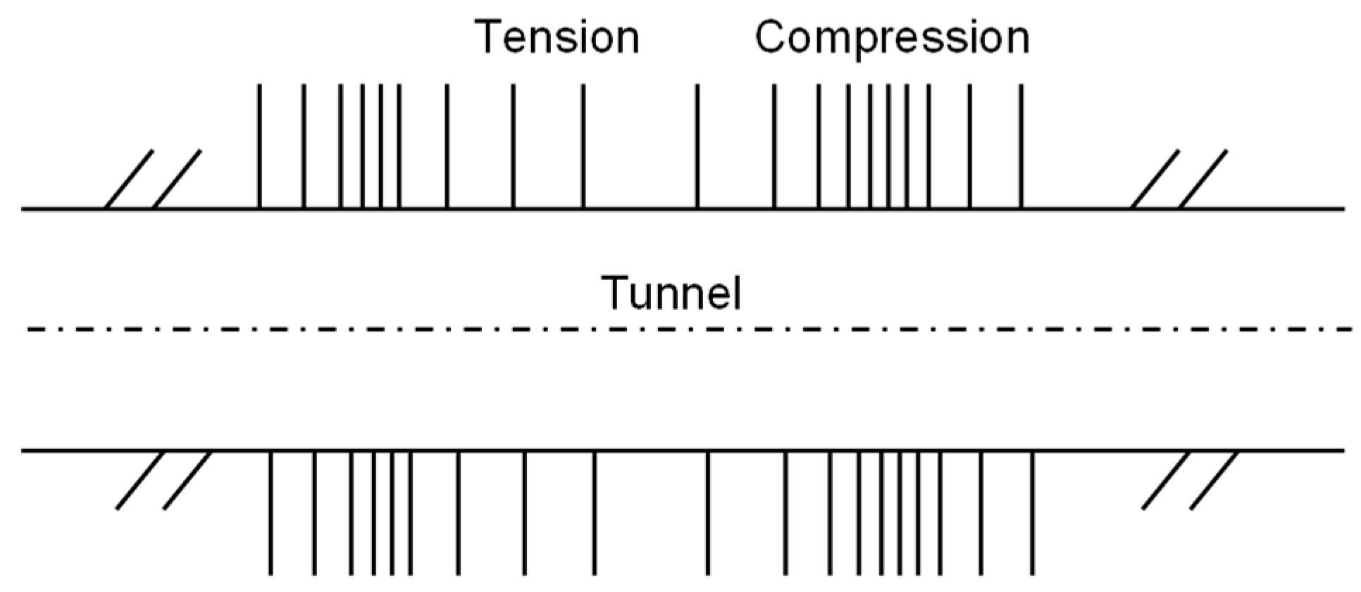
Figure 2.
Curvature deformation along the tunnel (adapted from [5]).
Figure 2.
Curvature deformation along the tunnel (adapted from [5]).
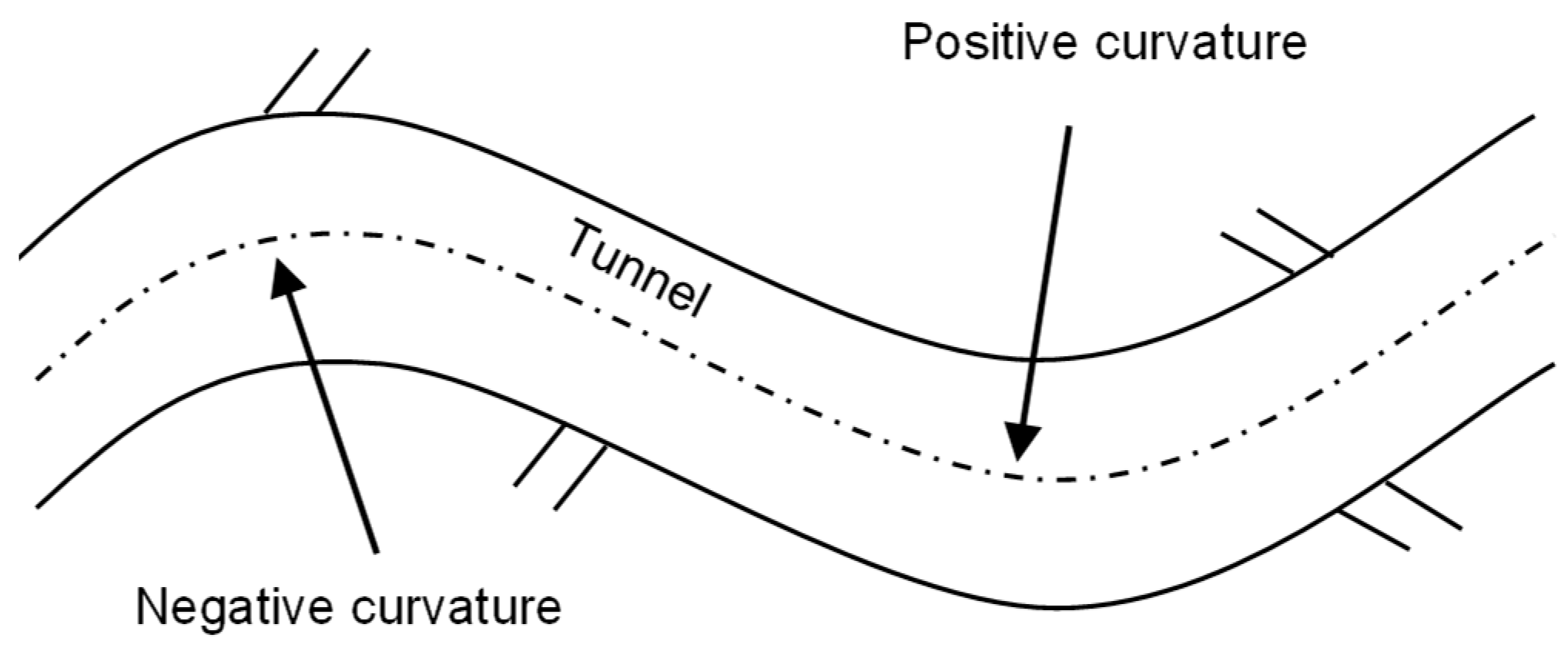
Figure 3.
Racking behaviour due to vertically propagating shear wave (adapted from [6]).
Figure 3.
Racking behaviour due to vertically propagating shear wave (adapted from [6]).
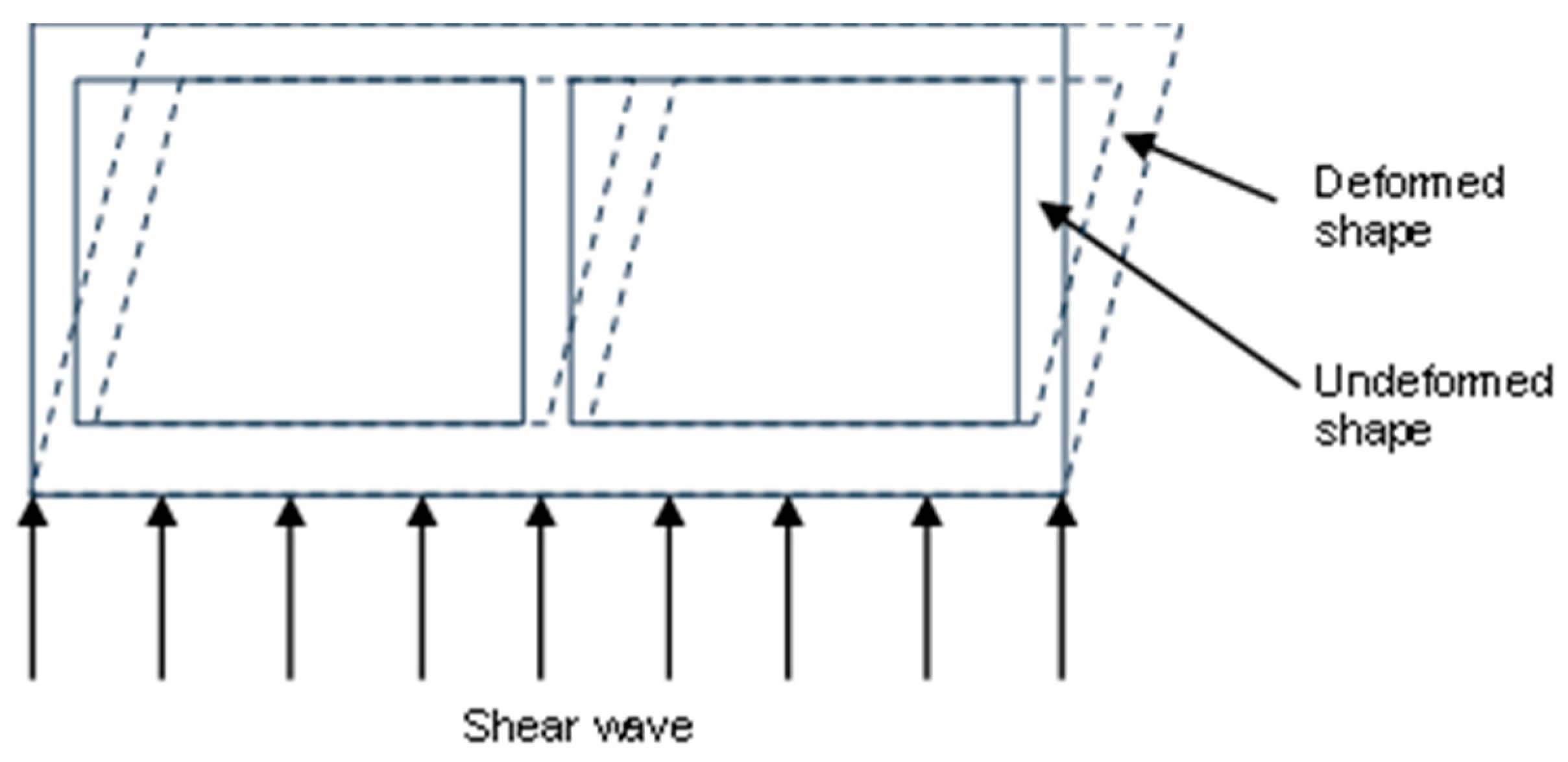
Figure 4.
Steps for seismic design (adapted from [4]).
Figure 4.
Steps for seismic design (adapted from [4]).
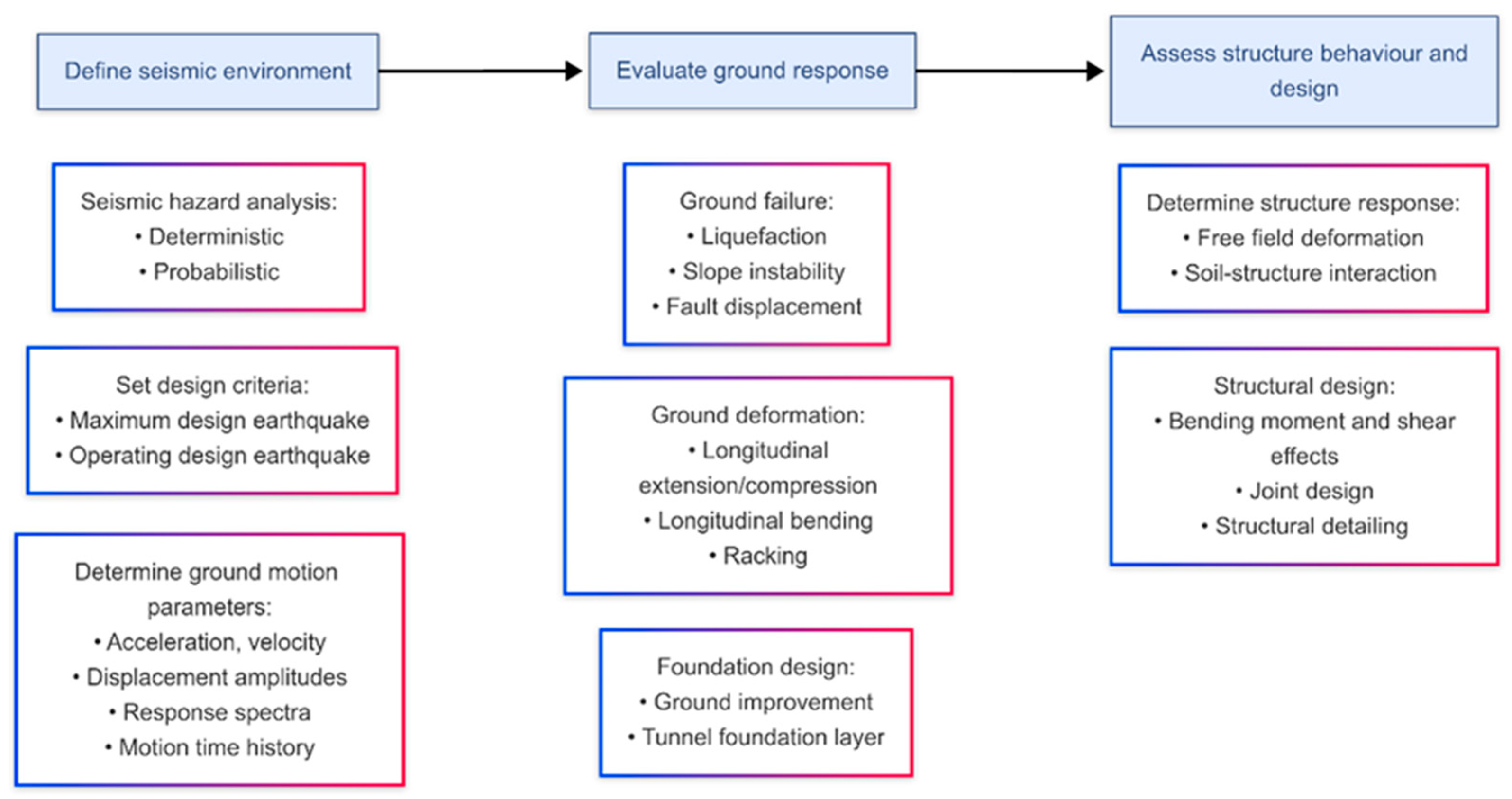
Figure 5.
Finite-element model: (a) 3-D view; (b) longitudinal section (reproduced with permission from Anastasopoulos et al. [13]).
Figure 5.
Finite-element model: (a) 3-D view; (b) longitudinal section (reproduced with permission from Anastasopoulos et al. [13]).
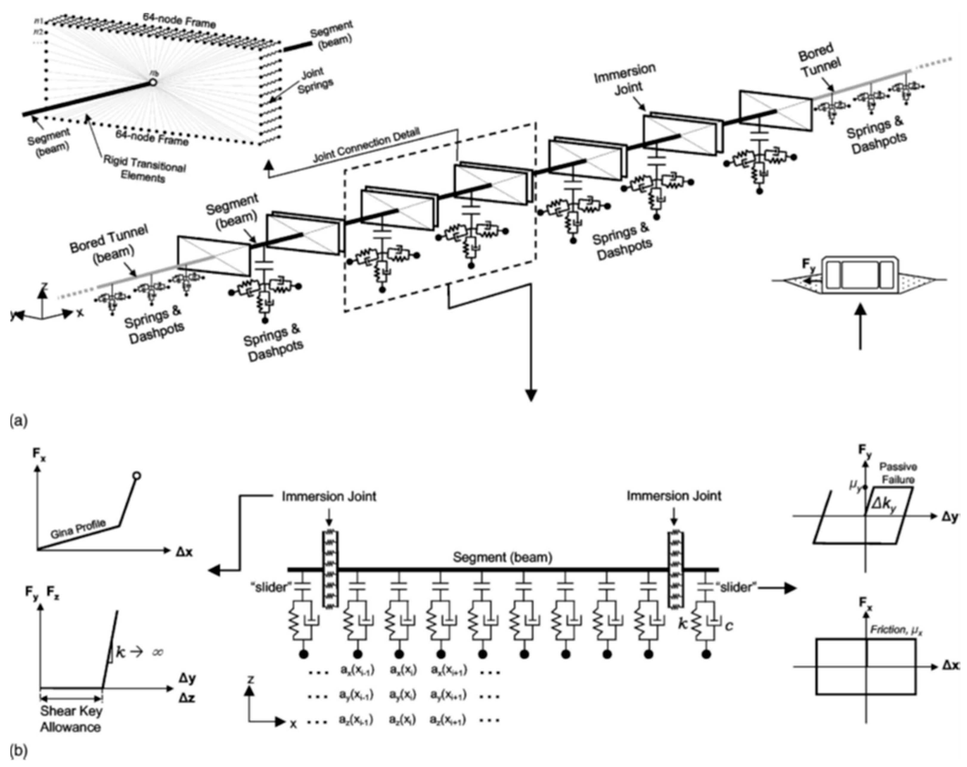
Figure 6.
Spatial model of the immersed tunnel - foundation system: a) global model; b) immersion joint; c) segment joint (reproduced with permission from Zhang et al. [14]).
Figure 6.
Spatial model of the immersed tunnel - foundation system: a) global model; b) immersion joint; c) segment joint (reproduced with permission from Zhang et al. [14]).
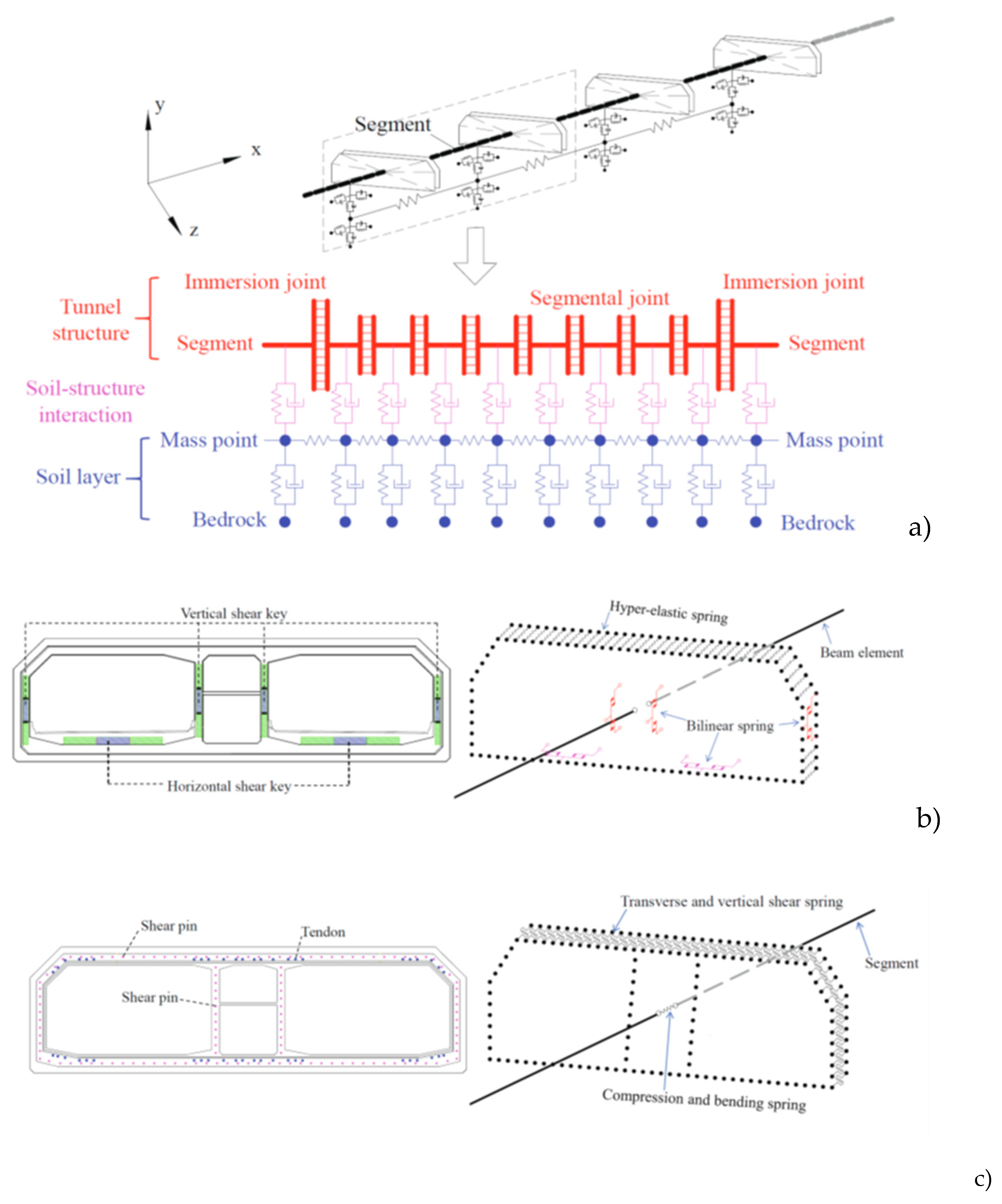
Figure 7.
Seismic immersed tunnel-water-sediment-rock interaction model: (a) finite element model; (b) immersed tunnel cross-section (reproduced with permission from Zhang et al. [16]).
Figure 7.
Seismic immersed tunnel-water-sediment-rock interaction model: (a) finite element model; (b) immersed tunnel cross-section (reproduced with permission from Zhang et al. [16]).

Figure 8.
Cross-section schematic diagram of the numerical model used to simulate the immersed tunnel-seabed-seawater coupling system (reproduced with permission from Chen et al. [17]).
Figure 8.
Cross-section schematic diagram of the numerical model used to simulate the immersed tunnel-seabed-seawater coupling system (reproduced with permission from Chen et al. [17]).
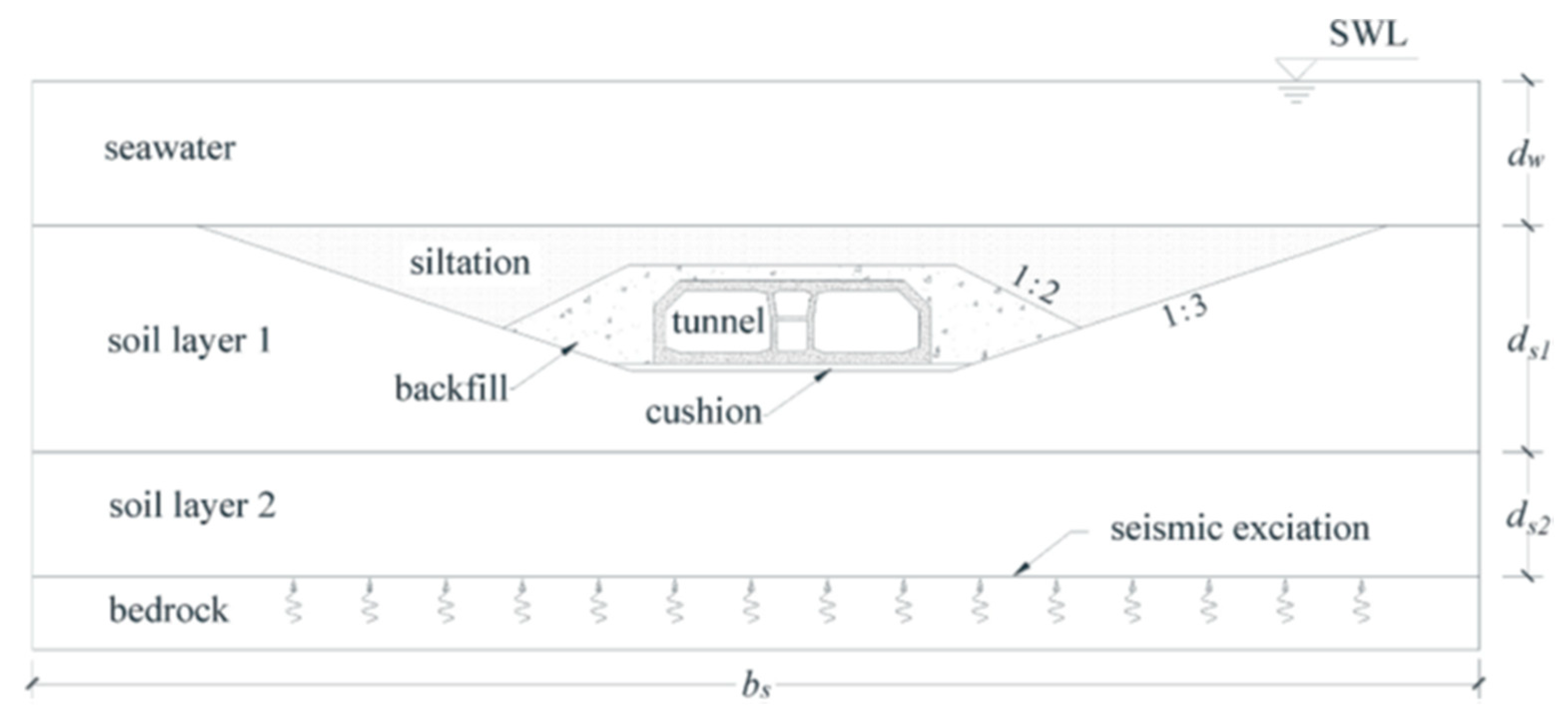
Figure 9.
Soil and immersed tunnel numerical models [18].
Figure 9.
Soil and immersed tunnel numerical models [18].
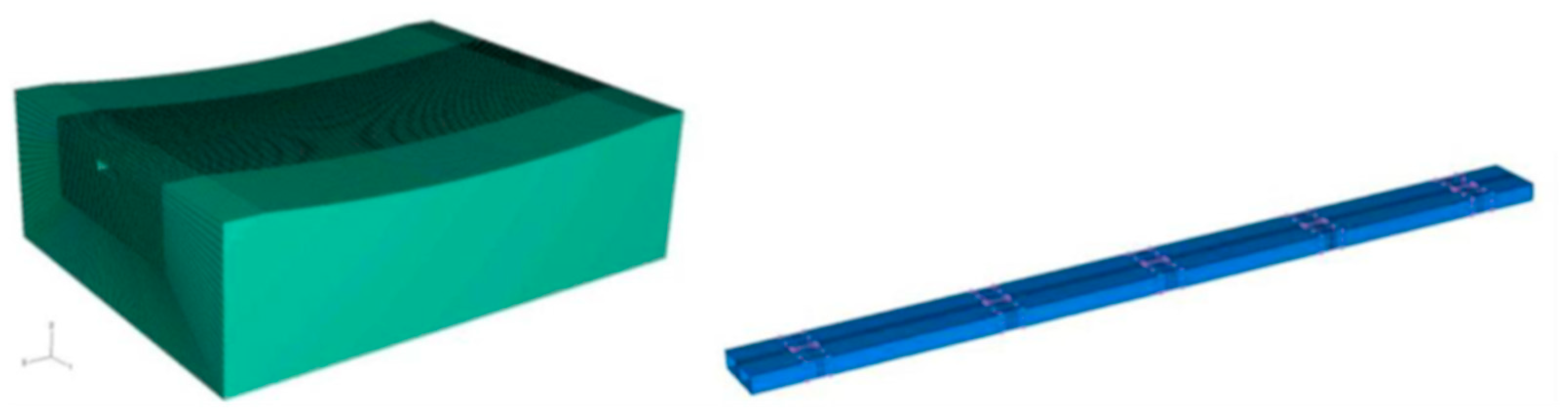
Figure 10.
Immersed tunnel element and soil-tunnel numerical models [19].
Figure 10.
Immersed tunnel element and soil-tunnel numerical models [19].
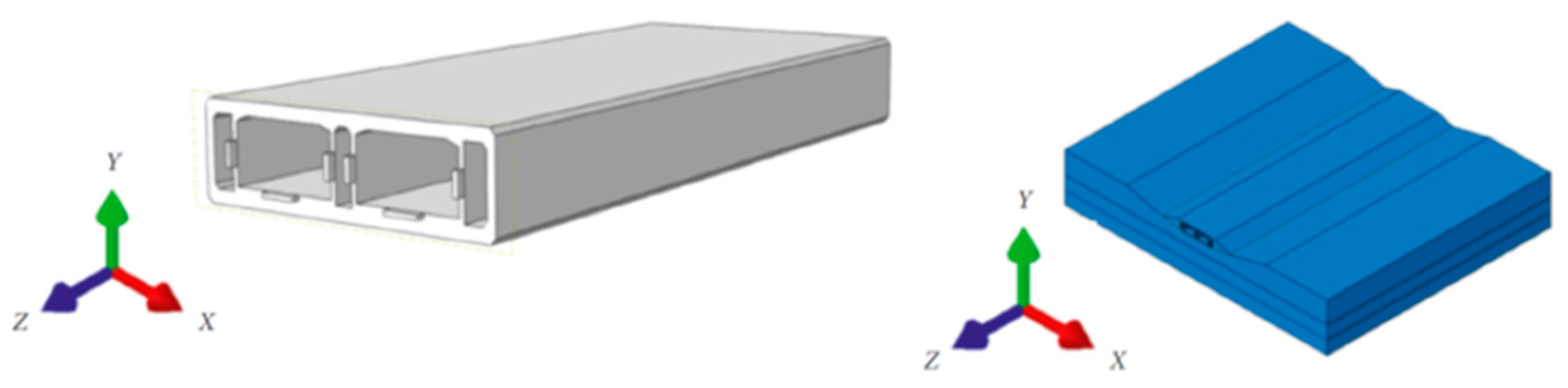
Figure 11.
Numerical model of the immersion joint and the tunnel segment (reproduced with permission from Xiao et al. [20]).
Figure 11.
Numerical model of the immersion joint and the tunnel segment (reproduced with permission from Xiao et al. [20]).
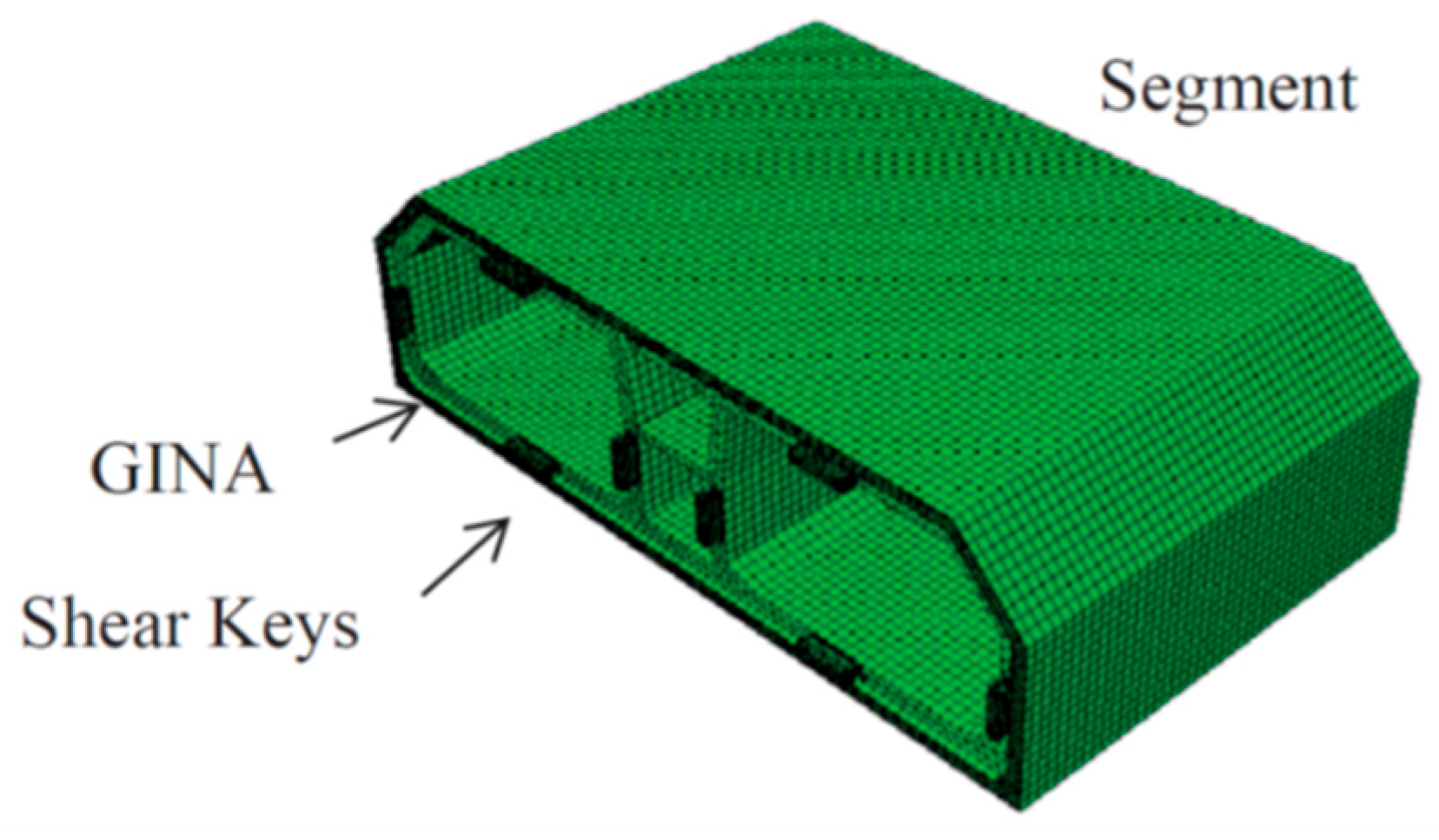
Figure 12.
Movement of liquefiable soil around the tunnel and ratcheting displacement of tunnel with alternate cycles of ground motion [29].
Figure 12.
Movement of liquefiable soil around the tunnel and ratcheting displacement of tunnel with alternate cycles of ground motion [29].
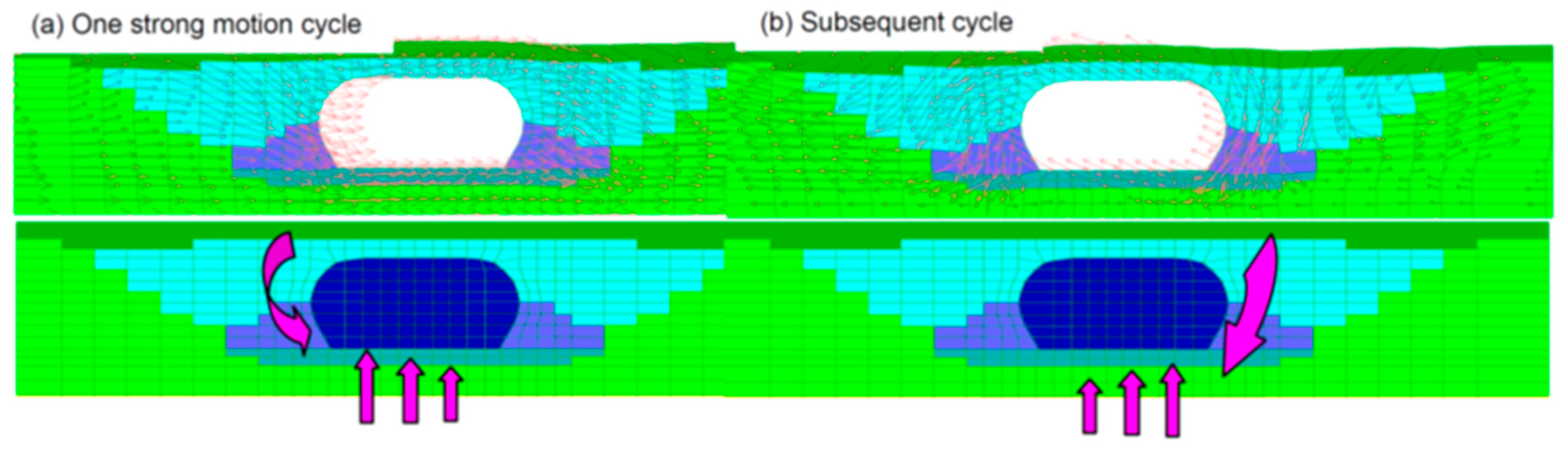
Figure 13.
Cross-section of the container with the model [32].
Figure 13.
Cross-section of the container with the model [32].
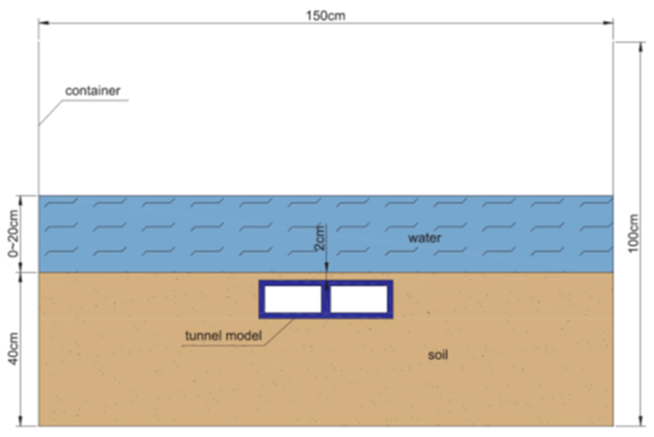
Figure 14.
Container and model element [32].
Figure 14.
Container and model element [32].
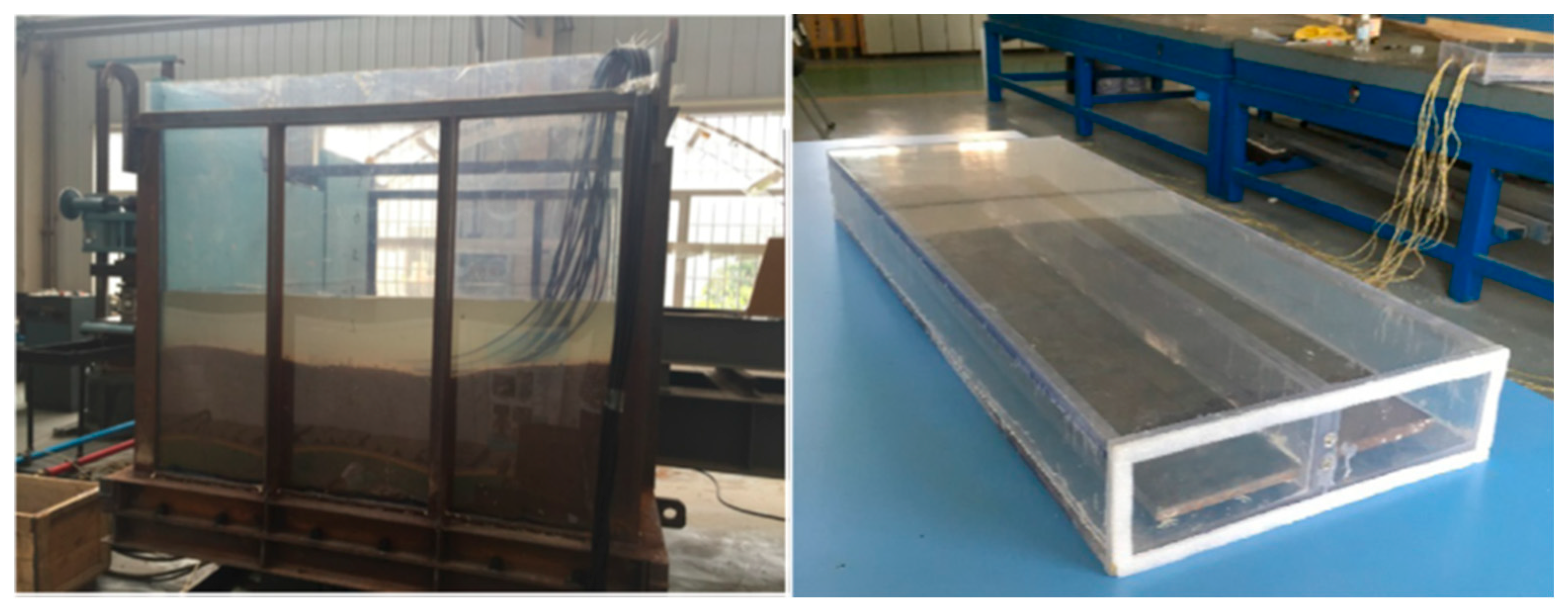
Figure 15.
Immersion joint model (units: mm). (a) Cross-section of the joint; (b) 1-1 cross-section; (c) 2-2 cross-section (reproduced with permission from Yuan Y et al. [34]).
Figure 15.
Immersion joint model (units: mm). (a) Cross-section of the joint; (b) 1-1 cross-section; (c) 2-2 cross-section (reproduced with permission from Yuan Y et al. [34]).
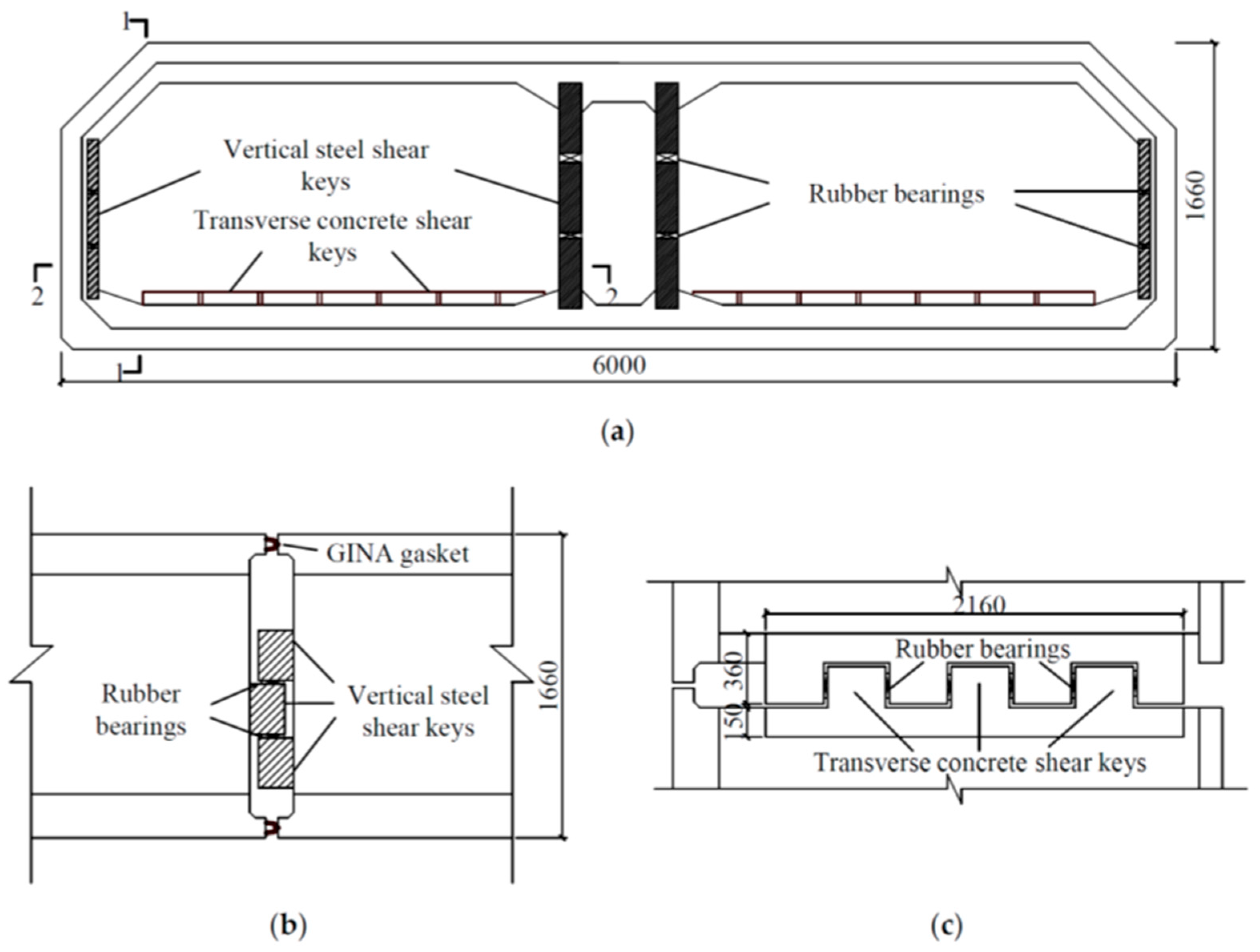
Figure 16.
TBT location (Google Maps).
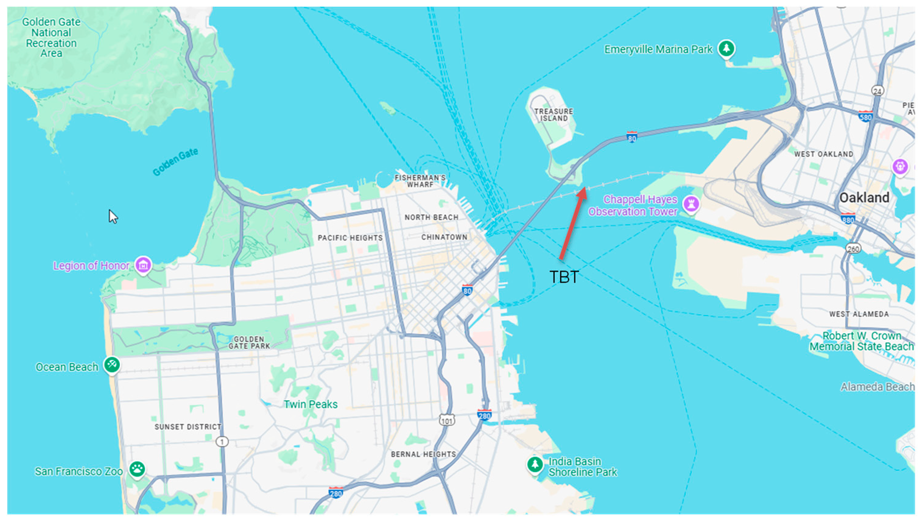
Figure 17.
TBT cross section (adapted from [29]).
Figure 17.
TBT cross section (adapted from [29]).
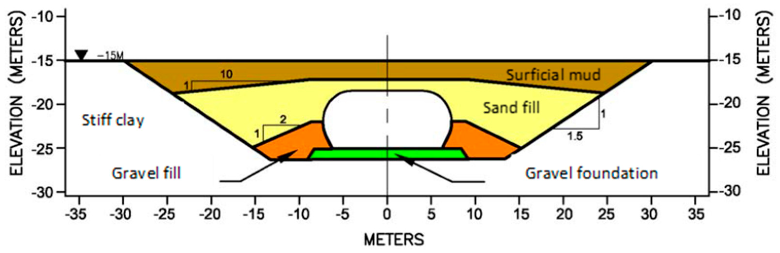
Figure 18.
TBT terminal seismic joint [35].
Figure 18.
TBT terminal seismic joint [35].
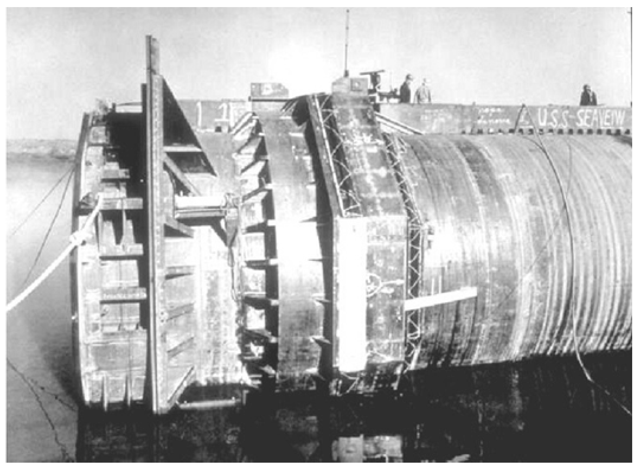
Figure 22.
Waihuan Tunnel cross section (mm) [41].
Figure 22.
Waihuan Tunnel cross section (mm) [41].
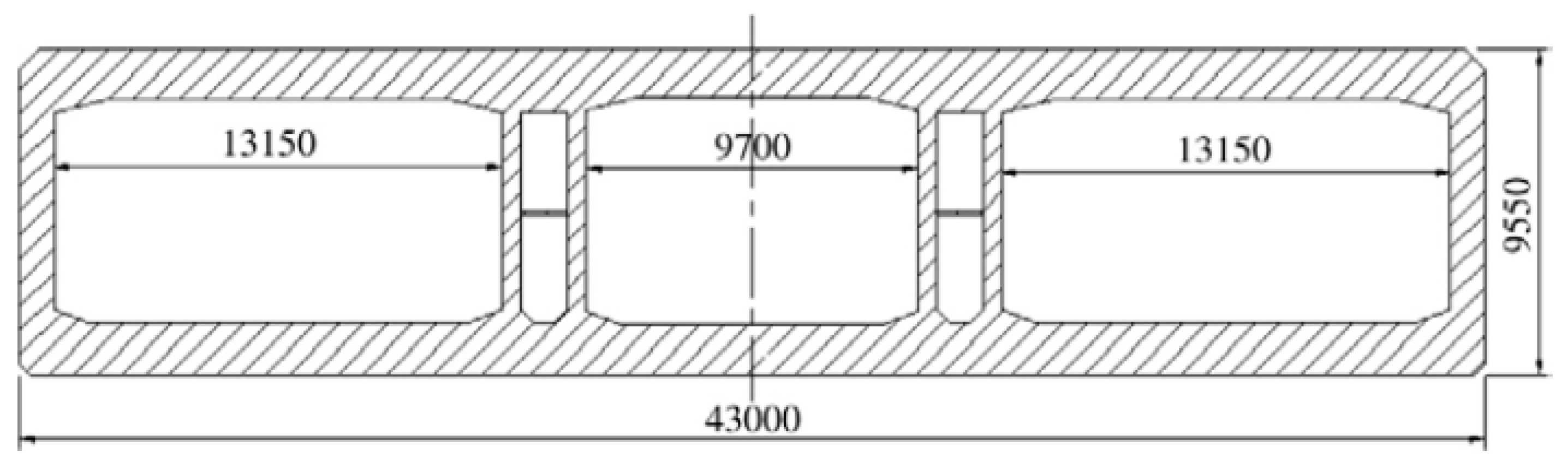
Figure 23.
Waihuan Tunnel general plan [41].
Figure 23.
Waihuan Tunnel general plan [41].
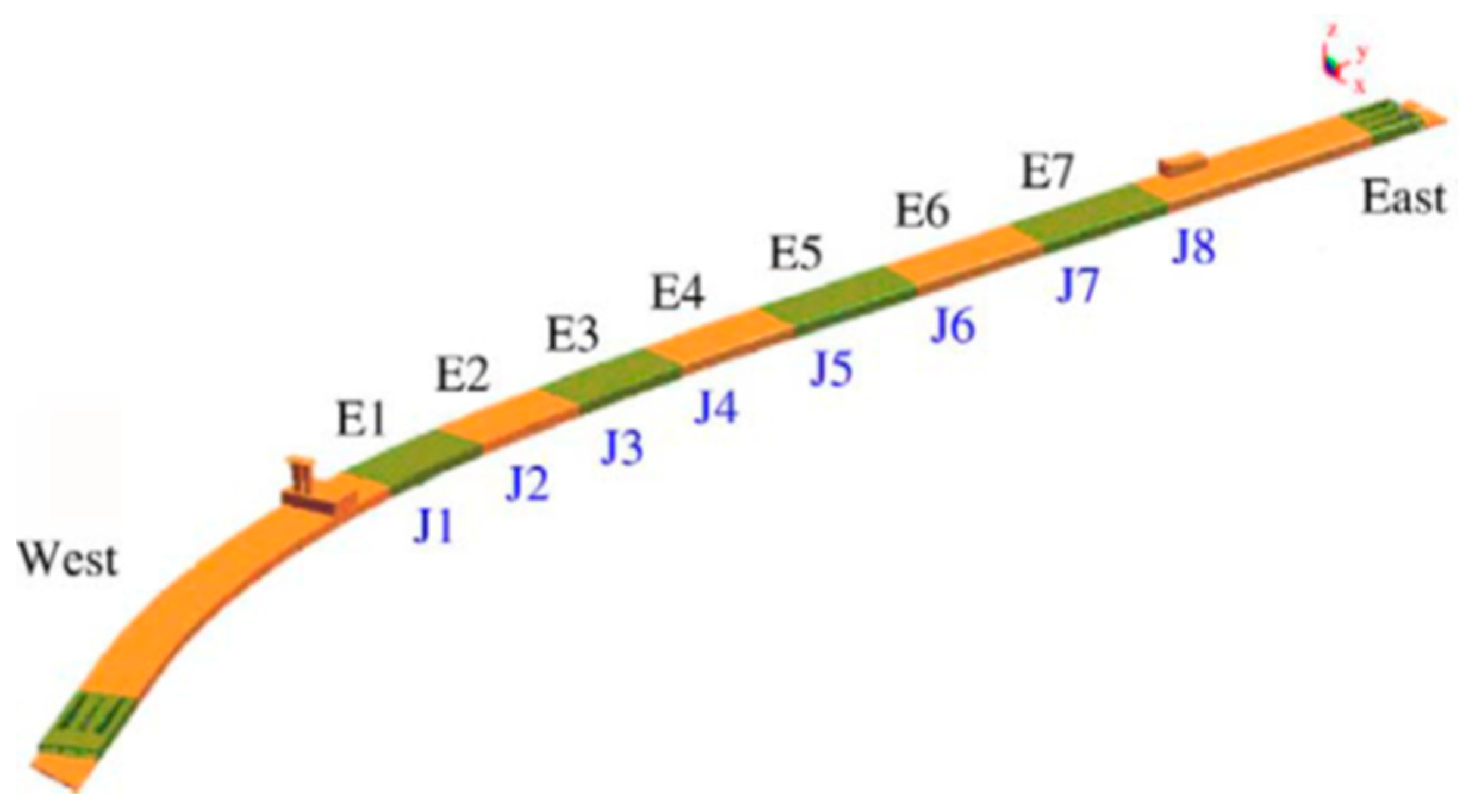
Figure 24.
Waihuan Tunnel global mesh [41].
Figure 24.
Waihuan Tunnel global mesh [41].
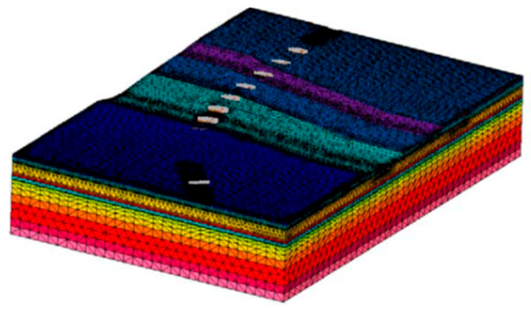
Figure 25.
Waihuan Tunnel flexible joint [41].
Figure 25.
Waihuan Tunnel flexible joint [41].
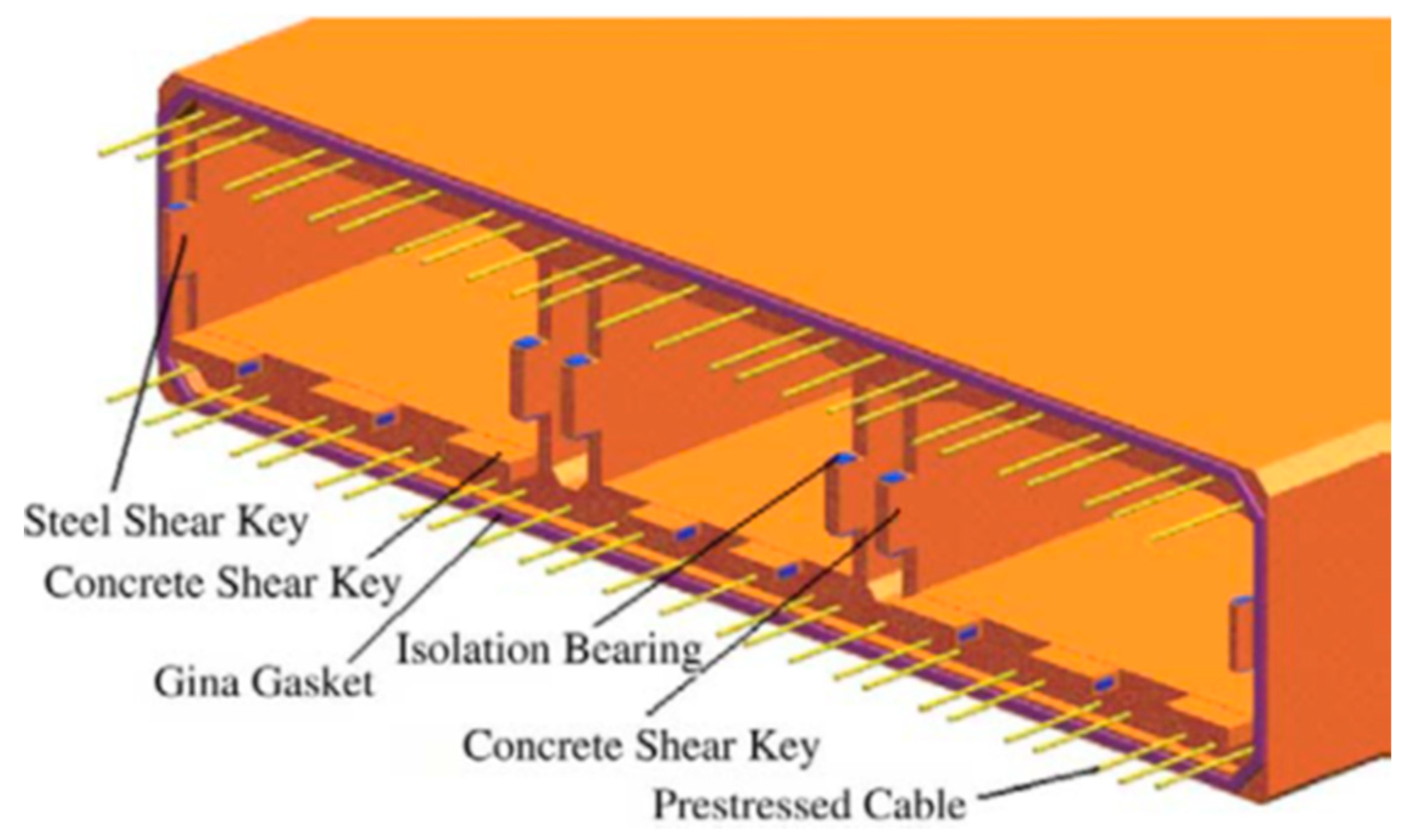
Figure 29.
Retrofit scheme with ground densification and drainage (reproduced with permission from [46] and COWI).
Figure 29.
Retrofit scheme with ground densification and drainage (reproduced with permission from [46] and COWI).
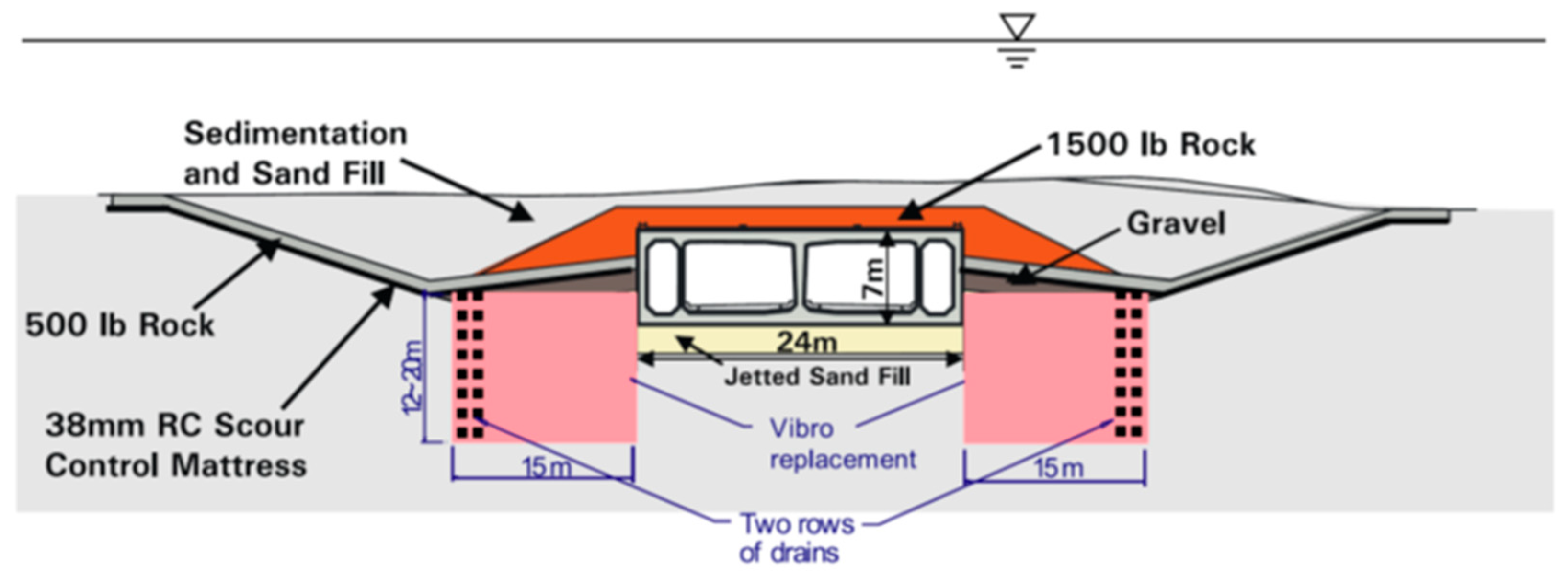
Figure 33.
Simplified model of the tunnel and surrounding ground [52].
Figure 33.
Simplified model of the tunnel and surrounding ground [52].
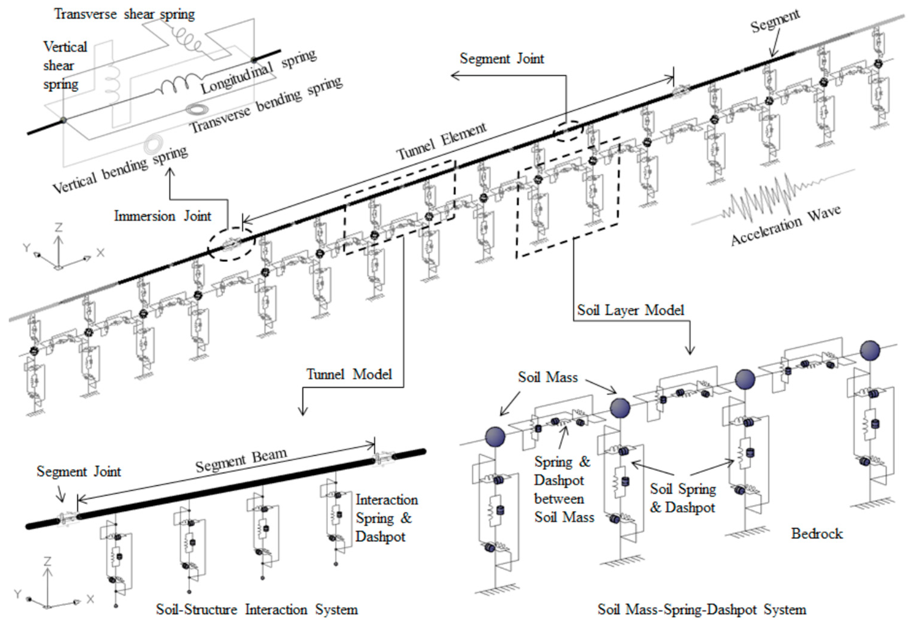
Figure 34.
FE model of the tunnel (reproduced with permission from Chen et al. [53]).
Figure 34.
FE model of the tunnel (reproduced with permission from Chen et al. [53]).
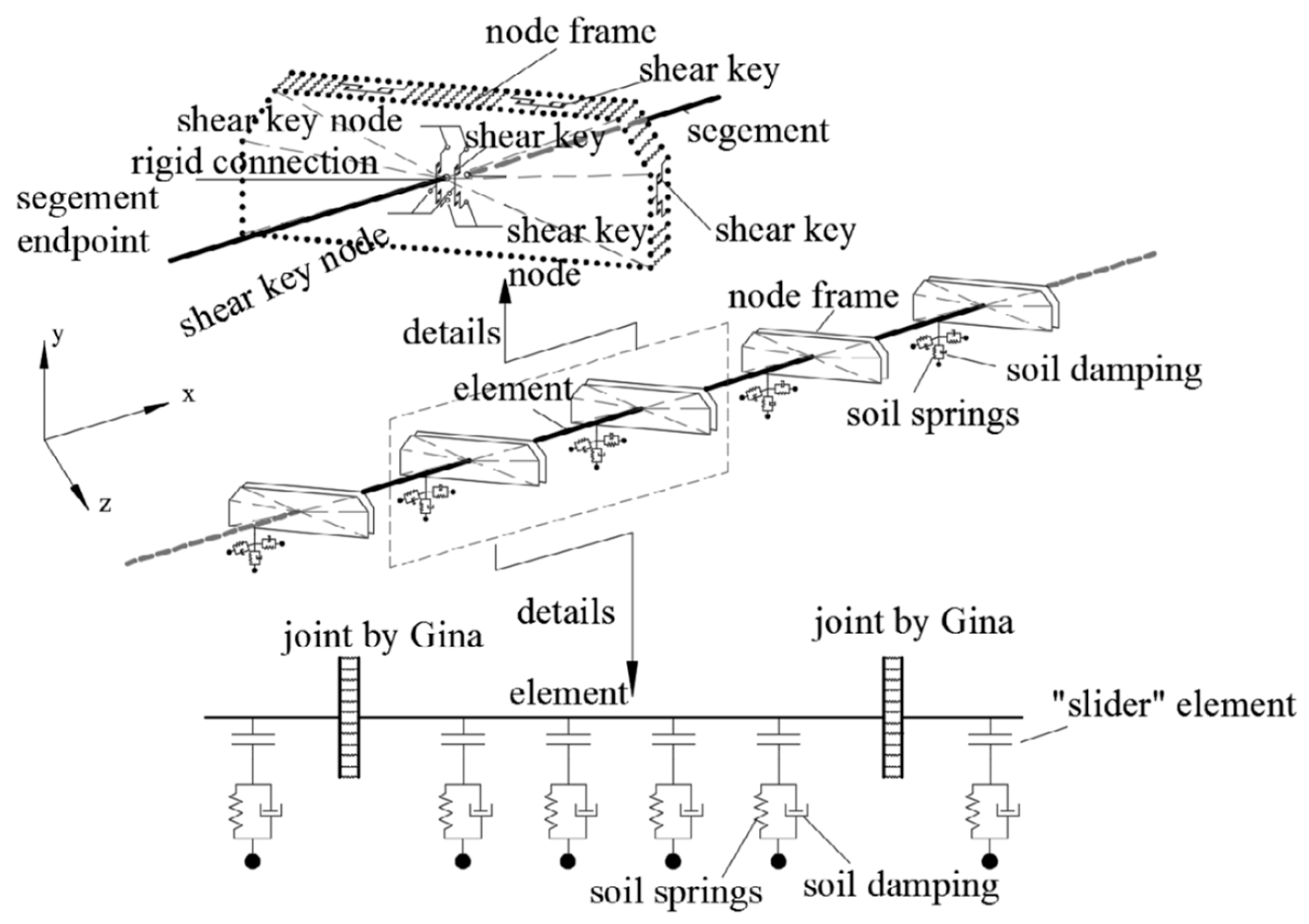
Figure 35.
Layout of the BRB device (reproduced with permission from Yu et al. [58]).
Figure 35.
Layout of the BRB device (reproduced with permission from Yu et al. [58]).
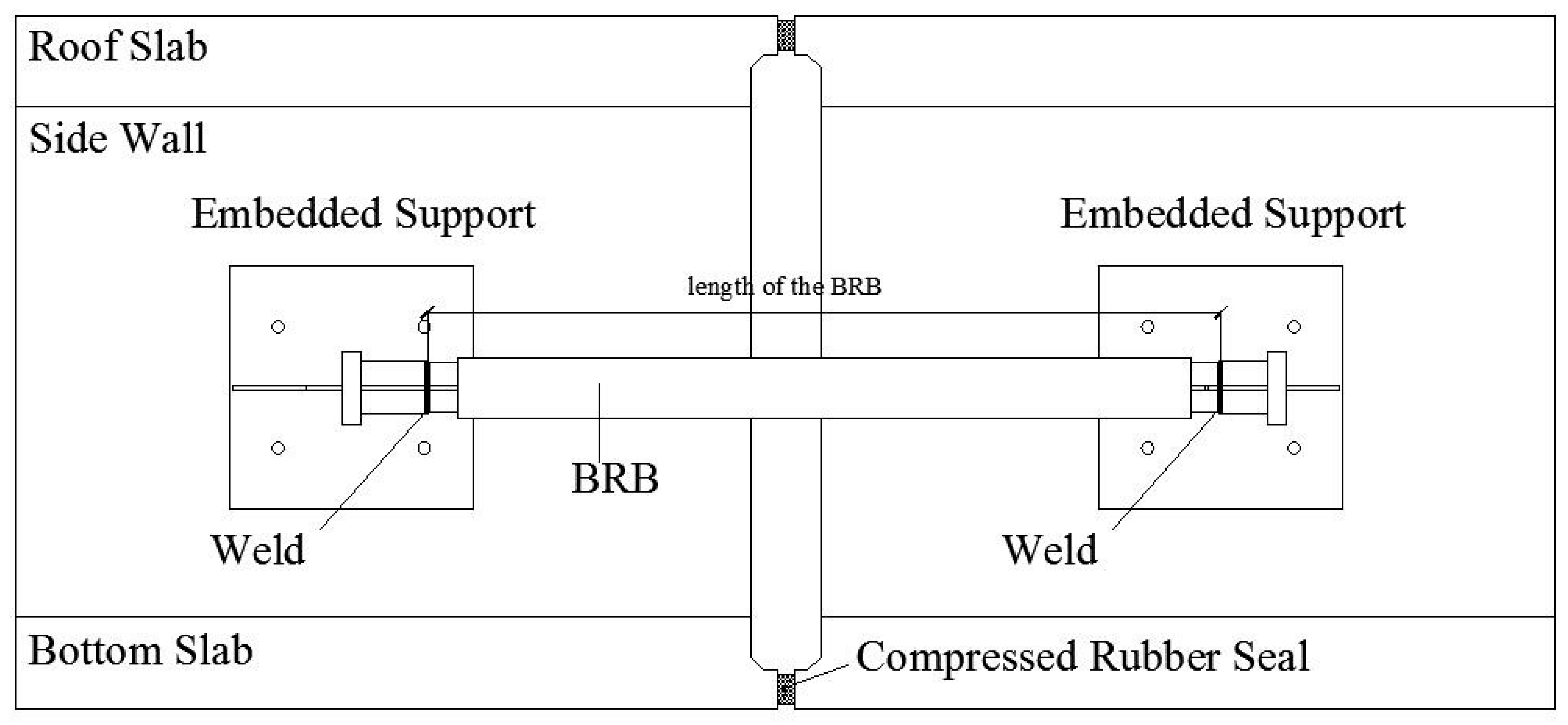
Figure 36.
Third Tagus River crossing location (Google Maps).
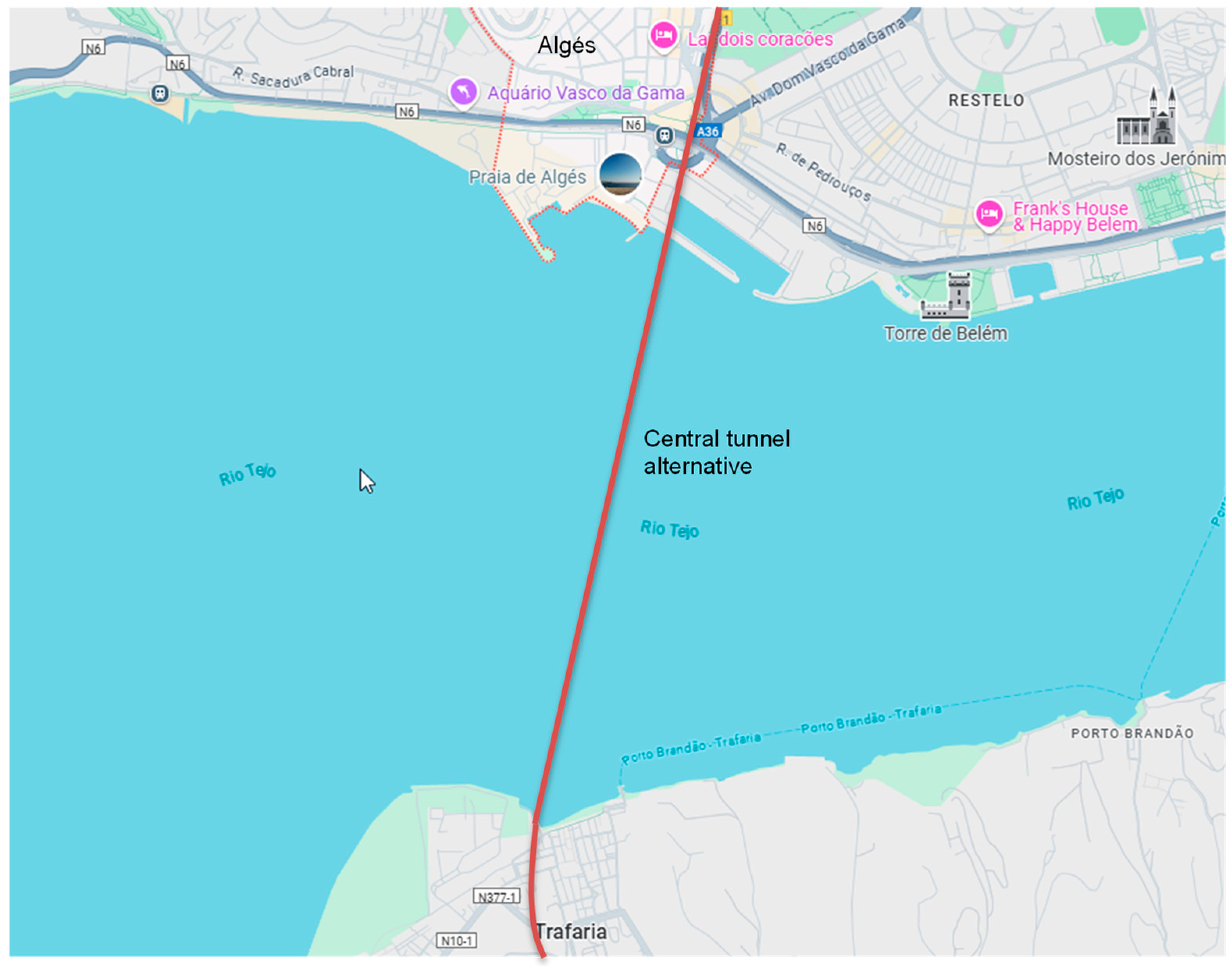
Table 1.
Main project characteristics.
| Project | Type | Elements length | Cross-section | Foundation ground | Fill material | Joints | Ground improvement |
|---|---|---|---|---|---|---|---|
| Offshore Transbay Tube | External steel shell with internal reinforced concrete | 100 m | Tubular, approximately rectangular (14.3 m width, 7.3 m height, 2 main cells) | Gravel foundation over stiff clay | Sand (minimum 1.5 m cover) / gravel | Specially designed terminal joints (allow longitudinal displacements of 0.08 m and vertical or transverse displacements of 0.15 m) | - |
| Posey and Webster Street Tubes | Pre-cast reinforced concrete | 60 m | Circular (external diameter of 11 m) | Loose sand layer over the Posey Formation (stiff to very stiff sandy silt to clayey silt) | Soft clay and loose sand | Sealed joints with steel and concrete (modified to accommodate expansion after retrofit). Special joints at the connections to portal buildings (after retrofit). | Stone columns on both sides of the Webster Street Tube (after retrofit). Jet grouting adjacent to the Posey Street Tube (after retrofit). |
| Waihuan Tunnel | Pre-cast reinforced concrete | 100-108 m | Rectangular (43 m width, 9.55 m height, 3 main cells) | Cohesive silts and clays | Silty clay and sandy silt | Flexible joints | - |
| George Massey Tunnel | Pre-cast reinforced concrete | 105 m | Rectangular (24 m width, 7 m height, 2 main cells) | Sand foundation layer over loose sand and interbedded sandy silt | Gravel and rock fill | Flexible joints between elements and stiff joints between the tunnel and ventilation structures | Vibro-replacement stone columns and vertical drains on both sides of the tunnel (after retrofit) |
| Hong Kong-Zhuhai-Macau Tunnel | Pre-cast reinforced concrete | 180 m (22.5 m segments) | Rectangular (38 m width and 11.4 m height, 2 main cells) | Gravel foundation layer over mostly soft soil layers composed of medium and coarse sand | Sand fill and gravel protection layer (cover up to 21 m due to sedimentation) | Flexible element and segment joints; segment joints allowable longitudinal and vertical displacements are 16 mm and 4 mm, respectively. |
PHC pipe piles, jet grouting, sand compaction piles |
| Tagus River crossing | Pre-cast reinforced concrete | - | Rectangular (40 m width and 11 m height, 2 main cells) | Gravel foundation layer over alluvial Tagus River sands | Gravel and rock protection fill (1.5 m cover) | Flexible element and segment joints | Polyurethane resin panels |
Disclaimer/Publisher’s Note: The statements, opinions and data contained in all publications are solely those of the individual author(s) and contributor(s) and not of MDPI and/or the editor(s). MDPI and/or the editor(s) disclaim responsibility for any injury to people or property resulting from any ideas, methods, instructions or products referred to in the content. |
© 2025 by the authors. Licensee MDPI, Basel, Switzerland. This article is an open access article distributed under the terms and conditions of the Creative Commons Attribution (CC BY) license (http://creativecommons.org/licenses/by/4.0/).
Copyright: This open access article is published under a Creative Commons CC BY 4.0 license, which permit the free download, distribution, and reuse, provided that the author and preprint are cited in any reuse.


