Submitted:
29 July 2025
Posted:
30 July 2025
You are already at the latest version
Abstract
This article presents an overview of selected reserach focusing on digital real-time simulation (DRTS) with the primary aim of intelligent fault diagnosis (FD) and condition-based monitoring (CBM) of electrical machines. Conventional multiphysics offline digital simulations are widely utilized in the conceptualization and development phases of industrial product manufacturing and processing, particularly for virtual testing under both standard and extreme operating conditions as well as for aging assessments and lifecycle analysis. Recent advancements in data communication and information technologies, including virtual reality, cloud computing, parallel processing, machine learning, big data, and the Internet of Things, have facilitated the creation of intelligent physical and mathematical models. These models are distinguished by their ability to enable real-time bidirectional data exchanges with physical systems. This article highlights recent progress and key challenges in this emerging field, with particular emphasis on real-time multiphysics modeling to enhance the efficiency of FD and CBM of electrical machines, which play a crucial role in industrial applications.
Keywords:
condition monitoring
; digital simulation
; digital twins
; electric machines
; hardware-in-the-loop simulation
; fault diagnosis
; machine learning
; predictive maintenance
; real-time systems
1. Introduction
Today, the design and implementation of industrial products are almost inconceivable without the initial phase of virtual prototyping supported by digital simulation (DS). DS enables the creation of a reference model that provides a precise description of a physical entity. This is commonly known as a digital twin (DT), which serves as a virtual representation of the product prior to physical prototyping [1,2,3,4]. This approach provides access to a broad range of variables that may not be directly measurable or may require sophisticated instrumentation. Using this method, industrial products can be developed more efficiently and cost-effectively through a comprehensive analysis of their entire life cycle. An important feature of the DS world is that every test and decision can be conducted and undesired conditions can be anticipated. This can facilitate tasks such as configuration, FD and CBM for preventive maintenance. Compared with real-world testing, DS offers significant time and cost savings while minimizing waste and reducing potential risks. Conducting experiments in a physical lab requires substantial time owing to the preparation and construction of experimental test benches. Additionally, laboratory testing is often constrained by facility capabilities, capacity limitations, and lack of flexibility when modifications are required. In a design process that involves multiple iterations, where each stage depends on the outcomes of the previous test, the resulting time delay can be substantial. Beyond saving time and cost, DS enables the exploration of a much wider range of variants. This gives product developers greater flexibility to innovate, test numerous combinations, and experiment with unconventional approaches, ultimately leading to a more refined and optimized solution. To accurately represent the physical world, DS must incorporate interactions across multiple physical domains, including electromagnetics, fluid dynamics, mechanics, thermodynamics, and materials science [5]. If DS results fail to accurately represent real-world conditions, they lose their value. Confidence in DS increases when its outcomes align with those obtained from physical tests and field experiences. Electrical machines are widely used in various industrial applications, including electric traction systems, hybrid and electric vehicles, wind and marine energy conversion, power generation, energy storage, shipboard systems, and aerospace electrification. To enhance their design and performance, digital offline simulation (DoS) is frequently used to optimize structural configurations, develop controllers, and analyze the dynamic behavior of innovative electrical machines [6].
The modeling of electrical machines can be broadly categorized into two main approaches: physics-based (PHYB) and data-driven. PHYB models primarily rely on the observation of physical phenomena and aim to represent them using mathematical formulations, which are then solved, either analytically or numerically. By contrast, data-driven models require large amounts of data during the training phase, which can be generated from partial PHYB models or experimental measurements [7]. The multiphysics modeling of electrical machines can capture various fields of physics, including electromagnetism, mechanics, vibro-acoustics, and thermal phenomena, and can be composed of several interacting PHYB or data-driven models [8,9,10,11]. Focusing on the electrical and magnetic aspects, literature commonly reports both simplified PHYB models using circuit-oriented lumped-parameter (COLP) approaches and detailed PHYB (DPHYB) models for electrical machine modeling [6]. The first relies on an electrically and magnetically coupled circuit, which is typically used for analyzing dynamic behavior of electrical machines and electromagnetic transient studies. It assumes perfect symmetry in both the field and construction, a constant air gap that is small relative to the rotor radius, a linear magnetic system, and omission of hysteresis effects. In contrast, the second method considers complex geometry, magnetic saturation, eddy current and hysteresis effects in detail and is employed for design purposes [6,12]. Clearly, the DPHYB models offer greater accuracy than the COLP models, but this comes at the cost of an increased computation time. The COLP model includes the dynamic ‘abc’ and ‘dq0’ reference frame models and the dynamic voltage-behind-reactance model in which the variables of the stator are described in the ‘abc’ reference frame and the variables of the rotor are given in the ‘dq0’ reference frame [12,13]. The ’dq0’ reference frame model can be derived from the ’abc’ reference model using Park transform, which eliminates time-varying inductances in the ’abc’ frame and simplifies the voltage equations in AC electrical machines. Self and mutual inductances of ’abc’ reference model is commonly determined based on the Winding Function Approach (WFA) or modified WFA (MWFA) when some data regarding the geometry of the machine is known [14]. Another approach is to perform basic experimental tests, through which it is possible to obtain these parameters for a simplified internal equivalent circuit model [15].
DPHYB models encompass both finite element method (FEM)-based and analytical models. In FEM-based models for electrical machines, Maxwell’s equations must be solved numerically for each mesh element, whether in 2D triangular or 3D tetrahedral configurations. Conversely, analytical models rely on explicit solutions of Maxwell’s equations and are widely employed to aid in design and analysis, particularly when an accurate calculation of the magnetic field distribution across various machine regions is essential. The accurate modeling of electric machines often relies on the FEM. However, finite element analysis (FEA) can be highly time-consuming, particularly during the initial design stages when conducting parametric studies. Two commonly used analytical models for design purposes are magnetic equivalent circuits (MEC) which relies on a permanence element network and models derived from the formal resolution of Maxwell’s equations in regions with constant permeability [16,17]. In an MEC-based model, the mesh network must be carefully designed to achieve an accuracy comparable to that of a FEM-based model. When considering the effect of iron magnetic saturation, the differential equation governing the MEC-based model transforms into a nonlinear representation of magnetic scalar potentials. To solve this, the Newton-Raphson method is typically employed, often in combination with an adaptive simulation time-step [18].
Data-driven modeling has gained significant attention owing to the development of advanced open-source machine learning (ML) and artificial intelligence (AI) tools, user-friendly and affordable computational resources, and extensive training materials. Unlike PHYB models, this approach operates under the premise that data encapsulates both explicit and implicit physical behaviors. Therefore, when trained on sufficiently large datasets, data-driven models can independently uncover underlying physical relationships. In particular, deep learning has enabled models to achieve near-human or even superhuman performance in tasks once considered out-of-reach by computers. These models can typically be categorized into six types: supervised and unsupervised linear models, supervised and unsupervised nonlinear models, and unsupervised deep learning approaches [19]. Although the performance of data-driven models depends on the widespread availability of large-scale/big data, the proposed methodology seeks to address the limitations of relying solely on either PHYB or data-driven modeling techniques. This integrated approach, known as hybrid modeling, combines the clarity, theoretical grounding, and insight of PHYB models with the precision, computational efficiency, and pattern recognition capabilities of advanced ML and AI methods. Hybrid modeling can be conceptualized as existing at the intersection of large-scale/big data, physics-informed modeling, and data-driven techniques, as illustrated in Figure 1 [7,20]. For example, instead of relying on computationally intensive FEA, a deep neural network (DNN) is employed as a surrogate model. The DNN was trained in a supervised manner using a large dataset generated from precomputed FEA results. During inference, the outputs of network intermediate are utilized as inputs for the PHYB post-processing step, which computes characteristic maps and key performance indicators. This hybrid strategy demonstrates a significant reduction in computational time while preserving flexibility within the simulation workflow of electrical machines [21].
The DoS concept has been widely applied in the development of fault diagnosis (FD) and condition-based monitoring (CBM) strategies for electrical machines. This approach primarily focuses on creating models that accurately incorporate various fault types, including bearing defects, static, dynamic, or mixed eccentricity, open or unbalanced circuits, short circuits in stator or rotor windings, insulation degradation, damage to rotor bars and end rings in squirrel-cage induction machines (SCIM), and demagnetization in permanent magnet synchronous machines (PMSMs) [22,23,24,25]. DoS enhances the clarity of fault signatures in physical variables that are often influenced by noise and the inherent imperfections of sensors used in experimental test setups. This makes it possible to effectively analyze early stage faults. A digital real-time simulation (DRTS) corresponds to a DoS that must operate within real-time processing constraints. In other words, the discretized model must be sufficiently swiftly computed to synchronize with real-world timing [26]. Therefore, the selected solver must be optimized to resolve the system equation within a specified time-step. DRTS is more advantageous than DoS because it can be linked to external equipment for design, test control, and robustness analysis in a hardware-in-the-loop (H-i-L) framework. H-i-L systems have been essential in the aerospace industry and in flight simulations for several decades [27,28]. Their application has expanded significantly in various fields, including powertrain modeling for electric vehicles, energy management in microgrids, power and energy systems, and the dynamic performance analysis of power electronic devices. Recently, this concept was proposed for the development of advanced fault diagnosis methods for electrical machines [15,29,30,31]. DRTS contributes to the FD and CBM of electrical machines by incorporating technologies such as virtual reality or DT, data analytics, large-scale/big data, Internet of Things (IoT), and machine learning which have been widely adopted in Industry 4.0 revolution. DT, which defines adaptable mapping of a physical system to a virtual replication [32], is a powerful and emerging technology that enables the representation of the state of health of complex systems and facilitates CBM [33,34]. This article provides an overview of selected papers on the topic of multiphysics DRTS in the context of DT for intelligent FD and CBM of electrical machines. Section II reviews the definition of DT, its emerging concepts, and the various levels and scales at which it is applied. Section III discusses the main challenges of DRTS as an enabling tool within an electrical machine DT platform. Section IV explores whether multiphysics RTDS can contribute to intelligent FD and CBM of electrical machines. Finally, the conclusion summarizes the key points and offers perspectives for future research in this domain.
2. Electrical Machine Digital Twin
2.1. Digital Twin Definition
The notion of a DT can be traced back to NASA in the 1960s, when it emerged as a dynamic representation of Apollo missions. Following the explosion of an oxygen tank and damage to the main engine during Apollo 13, NASA employed several simulators to investigate the root causes of malfunction. They enhanced their physical model of the spacecraft by incorporating digital elements, creating an early version of what is now known as DT. This system allows for continuous data input, supporting both forensic analysis of the incident and the planning of subsequent actions [37]. Since its initial development, the concept of DT has gained significant attention from both academia and industry. Figure 2 illustrates the timeline of DT evolution, starting from its inception [35,36]. Numerous reviews and state-of-the-art articles have focused on enabling technologies, existing challenges, and methodologies for leveraging DT in product lifecycle management and innovation [35,38,39,40]. Scholars and institutions have proposed various definitions and interpretations of DT, comprehensive discussions can be found in [19,35,39,40,41]. For instance, Vrabic et al. [42] characterized DT as a digital counterpart of a physical asset or system, enhanced with integrated simulations and service-related data. The digital model aggregates data from multiple sources throughout the product lifecycle, which is regularly updated and represented in different formats to forecast both current and future states in design and operational contexts, thereby supporting improved decision making [39]. According to Tao et al. [38], a DT can be characterized as a high-fidelity simulation that integrates multiphysics and multiscale modeling, incorporating probabilistic elements. It dynamically mirrors the state of its physical counterpart using a combination of historical information, real-time sensor inputs, and physical modeling. Similarly, Rasheed et al. [7,19] defined DT as a virtual model of a physical system that utilizes real-time data and digital simulations to enable monitoring, control, optimization, prediction, and informed decision-making. Unlike traditional digital models or digital shadows, DTs are distinguished by a fully bidirectional data flow between their physical and digital counterparts that allows any change in the physical system to be immediately reflected in its digital representation [39]. More recently, Rasheed et al. [19] presented a comprehensive survey of emerging applications of DT technology in the wind turbine industry. This study presents widely recognized definitions of DT from leading organizations and researchers, including Gartner, NVIDIA, IBM, DNV, GE Digital, Siemens, Oracle, Microsoft, the Digital Twin Consortium, Trauer et al., Grieves & Vickers, and the Industrial Digital Twin Association. Table 1 summarizes these recent definitions based on key aspects: ’Things,’ which indicates the scope of application covered by each definition; ’Representation,’ which refers to the realization space of the digital model; ’Data,’ which outlines how information is utilized; and ’Purposes,’ which identifies the primary objectives of DT development.
The definition of DT can fall within its capabilities and levels, which are classified as standalone, descriptive, diagnostic, prescriptive, and autonomous [19]. Standalone DT represents the foundational level, primarily utilized during the design phase. It relies on a DoS approach to enable cost-effective system evaluation prior to physical construction. At the descriptive level, a CAD model combined with real-time sensor data is used to reflect physical assets. This setup relies on a precise PHYB, that supports data interpolation in the targeted areas of interest. At the diagnostic level, powerful ML tools can be applied to data to support FD, and CBM. Using insights from diagnostic DT, human experts can intervene early to make necessary adjustments, prevent minor issues from escalating into major problems. Unlike standalone, descriptive, and diagnostic DTs, which do not offer foresight, the predictive DT continuously deliver updated predictions by leveraging real-time data streams from the physical entity. Prescriptive DT are valuable for optimizing asset control, as it generates recommendations based on what-if scenarios, risk assessments, and uncertainty analysis. This capability is especially beneficial for decision support systems, offering guidance to experts who then determine the appropriate course of action. In the final stage, DT and its physical counterpart engage in continuous two-way communication. The physical asset updates the DT in real time, whereas the twin, in turn, issues control commands to steer the physical system toward optimal performance. This enables rapid decision-making without requiring human intervention. Referred to as autonomous DT, this fifth level requires a high degree of technological maturity, particularly for deployment in safety-critical applications [19]. Industrial platforms such as General Electric’s ’Predix,’ Siemens’ ’MindSphere,’ and ’ThingWorx’ support the development of DTs by leveraging Internet of Things (IoT) technologies. IoT extends digital connectivity into the physical environment through widespread use of radio-frequency identification (RFID) chips embedded in real-world devices [43]. Although IoT offers significant benefits, it also presents major challenges related to IT infrastructure, connectivity, data privacy, security, trust, and data management [39]. In this context, data analytics plays a critical role in collecting, cleaning, and processing data for further analysis. The data cleaning stage particularly through imputation techniques is essential for addressing errors or missing values, ensuring the quality and reliability of the data before analysis.
2.2. Electrical Machine DT Realization
Drawing from the diverse range of existing DT definitions, the authors proposed a predictive level framework with the following vision for the DT design of an electrical machine in the service phase [34,38,41]:
- The DT of an electrical machine is a synchronized, ultra-fidelity replica of it, incorporating multiphysics, multiscale, and probabilistic modeling.
- An automated, bidirectional, real-time flow of data occurs between the DT and the electrical machine through appropriate instrumentation and the IoT platform.
- The twin encompasses data from the service stage of the electrical machine’s lifecycle and remains connected to this phase through to the retirement stage.
Figure 3 represents the scheme of electrical machine DT realization based on IoT and cloud-computing technologies for FD and CBM. The physical electrical machine in this configuration is fully instrumented using RFID smart sensors to collect data on voltage, current, vibration, acoustics, temperature, speed, and mechanical torque. Quantities such as the active, reactive, and apparent power can be computed based on the measured stator voltages and currents. The implemented sensors describe the conditions of the electrical machine supplied by an electrical drive. The last device adjusts the operating point of the electrical machine according to its health state. The RFID smart sensors and electrical drive are connected via an IoT infrastructure to a cloud-computing platform, as shown in Figure 3. The cyber layer of this structure enables secure bidirectional data transfer among smart sensors, electrical drive and cloud-computing platforms. In the next section, the DRTS challenges are discussed, as they are considered a fundamental stage for the predictive level framework for the DT design of electrical machines in the illustrated configuration (Figure 3).
3. Electrical Machines DRTS Challenges
3.1. Electrical Machine Models
In addition to DT, other terms have been introduced to clarify its workings in the real world, including physical entities, physical objects, physical things, physical assets, physical processes, physical products, real-world entities, physical systems, and physically manufactured products, as well as its workings in the digitally generated virtual world, including virtual entities, virtual dynamics, virtual representations, digital representations, and digital exact replicas (Table 1). DPHYB, COLP, data-driven, or a combination of these models can be used to build the DTs of electrical machines. As mentioned in the introduction, data-driven models, despite exhibiting stable behavior after the training process, require extensive historical data (big data), that can be obtained from the collected information. They are simpler to configure, typically do not require detailed physical entity parameters, and can operate faster than real-time models. However, they operate as black boxes and the presence of biased data can manifest in the model, resulting in unpredictable errors and uncertainties. The PHYB and COLP models have significant advantages, because they operate based on a solid physics foundation, resulting in estimated errors and uncertainties which are important criteria in fault management systems. Hybride modeling as shwon in Figure 1 can be considered as a good alternative but this approach is rarely used for modeling of electrical machines [21,44].
The PHYB and COLP modeling approaches can be categorized into experimental and numerical models. Experimental modeling involves conducting reduced or full-scale experiments to determine the main parameters of the electrical machine model [15,45]. To enhance the physical authenticity of a DT, it is necessary to solve the governing equations obtained from the physical modeling. In some cases, analytical solutions can be derived for simplified equations. However, owing to their complexities, numerical solutions are often obtained using computers [7,46,47]. The main aim is to analyze quantities that are commonly difficult or costly to measure directly. These models can subsequently be employed within the context of Figure 3 as the DTs for electrical machines. The traditional approach involves creating a COLP dynamic ‘dq0’ reference model for AC electrical machines [48,49]. The estimation of model parameters can be used for fault diagnosis. Although several techniques have been proposed for the identification of AC electrical machine parameters, they are commonly performed offline, limiting their application to DT realization. Another approach relies on residual computation using parity equations, state observers, or state estimators. This technique has been used extensively in sensor fault detection and diagnosis systems. Such dynamic models are simple enough to be used in DRTS and DT realizations, as presented in [12]. However, they omitted the magnetic saturation effect and assumed a sinusoidal winding distribution. Moreover, the machine is assumed to be perfectly symmetrical. The ‘dq0’ reference frame models are commonly preferred for simulating electromagnetic transients because the ‘abc’ reference frame models have time-varying inductances. This means that, to solve the governing equations, the inductance matrices must be inverted at each time-step during the digital simulation, in addition to the computational burden of each digital simulation step [12]. Despite the aforementioned inconvenience, the ‘abc’ reference frame has the advantage of being easily applicable for modeling multi-phase electrical machines, regardless of asymmetry in both stator and rotor circuits, and can account for all space harmonics in the electrical machine [50,51,52]. In this regard, it is possible to include certain inherent asymmetries in the physical electrical machines in the model. Induction machines (IMs) that are broadly utilized in the industry are good examples [53].

Table 2.
COLP modeling of various fault types in the ’dq0’ reference frame.
| Fault types | References |
|---|---|
| Broken rotor bar and end ring | [54,55,56,57,58,59] |
| Stator/rotor windings unbalance | [60] |
| Stator/rotor windings short circuit | [14,55,56,61,62,63,64] |
| Static, dynamic or mixed eccentricity | [55,65] |
| Ball bearing and race | [66] |
| Magnetization-related | [67] |
The equations representing the dynamic of a p-pole, three-phase, wye-connected IMs in the ‘abc’ reference frame is given by [68]:
with
where , and denote the voltage, current, and flux linkages, respectively. The subscripts and denote the variables related to the stator and rotor circuits, respectively. and represent the stator and rotor resistance matrices in the diagonal form, respectively. and denote stator and rotor windings inductances, respectively. is the angular separation of the stator’s and the rotor’s axes. represents the mutual inductance between the stator and the rotor windings. The superscript ′ is the representation of variables refers to the stator windings. The relationship between the torque and rotor speed is defined as
where J is the moment of inertia (Kg.m2), B denotes the viscous friction (N.m.s), and . The governing differential algebraic equations represented by (1) and (2) can be reformulated into a first-order ordinary differential equation (ODE) (5) for the digital simulation of the IM model in the ‘abc’ reference frame [13]:
with
The relations (1) and (2) can be considered a baseline for modeling various types of faults, such as broken rotor bars, end rings, and stator winding ITSCs in IMs. For instance, a COLP model of a three-phase IM can be developed, to include an ITSC in one of its stator windings [61] (Figure 4). Main parameters of the three-phase IM that are modified in (1) and (2) due to a stator winding ITSC are the stator-related matrices: , , and . In these matrices, the parameters corresponding to the faulty segment are separated from those of the remaining winding. The proposed model can be extended to study simultaneous occurance of ITSC faults in the stator windings of an IM [14]. To investigate broken rotor bar or end-ring defects in squirrel-cage induction machines (SCIMs) using the COLP modeling approach, the rotor structure can be represented by the configuration shown in Figure 5. In this model, accounts for the resistance of the rotor bars and end-ring segments, while includes their self, leakage, and mutual inductances. Additionally, denotes the mutual inductances between each rotor loop or end-ring segment and each phase of the stator winding [69].
Table 3.
COLP modeling of various fault types in the ’abc’ reference frame.
| Fault types | References |
|---|---|
| Broken rotor bar and end ring | [70,71,72,73,74,75,76,77] |
| Stator/rotor windings unbalance | [15,31] |
| Stator/rotor windings short circuit | [14,70,78,79] |
| Static, dynamic or mixed eccentricity | [80,81,82,83] |
| Ball bearing and race | [84,85,86] |
| Magnetization-related | [87] |
The COLP modeling approach was initially developed for multi-phase winding structures of IMs, designed to operate even in scenarios where one or more of the stator phases are open-circuit, as discussed in [51]. The winding function approach (WFA) for computing self- and mutual inductances, which considers all space harmonics in a multi-phase IM, is presented. The proposed model includes asymmetry resulting from inter-turn faults in the stator phase windings, as well as any issue and number of failures in the rotor bars and end rings [52]. This type of modeling is crucial for fault diagnosis in AC electrical machines, where in many cases, space harmonics are required for efficient fault identification [88]. A universal mathematical model for a five-phase IM, encompassing the influence of higher space and time harmonics in the air-gap field, is presented in a similar manner. Given the significant role of space harmonics in AC electrical machines with more than three phases, mathematical relations for computing the self- and mutual inductances are derived [89]. To simplify the DRTS of the ‘abc’ reference frame model of the IM based on (5), both and are described through look-up tables as a function of [90]. This modeling approach can be extended to other electrical machine classes, such as permanent magnet synchronous machines (PMSM) [31]. In this regard, the classical ‘abc’ reference frame models of the IM and PMSM can be utilized for the DRTS of stator windings asymmetry fault. This illustrates the efficacy of such simple representations in detecting winding imbalance faults, as demonstrated in [14,15,91,92].
The use of PHYB models, especially FEM-based models that incorporate spatial and nonlinear aspects, as well as non-sinusoidal windings distribution phenomena inside the machine, can enhance fault detection performance. These models provide comprehensive information regarding the health state of a machine using residual signals. However, the computational intensity of these models and their size and time-step limitations render them unsuitable for DRTS applications. MEC-based models are generally considered to be a middle ground between FEM-based and COLP models in terms of their computational performance [6]. The concept of MEC-based modeling relies on the analogy between the electric and magnetic circuits. A deeper analysis of the electric and magnetic fields revealed that magnetic circuits typically function in a saturated, nonlinear mode, whereas the majority of the elements in electric circuits exhibit linearity. In this regard, the machine’s 2-D or 3-D structure must be divided into small elements that describe the MEC. Each element of the MEC model includes voltage and current sources and reluctances, which can be expressed as
where l represents the length of the flux tube and A denotes its cross-sectional area. denotes the permeability of the magnetic material. Figure 6 represents the 3-D MEC reluctance-based network and the circuit model of its elements. The voltage source, represents the magnetomotive force (MMF) and the current source, represents the flux of the permanent magnet. This network must be solved to obtain magnetic scalar potential, u, at each node. Based on the Figure 6.b it is possible to derive the following [6]:
Once the permeance and MMF are computed, the MEC relations can be determined based on the classical circuit nodal analysis.
Flux tubes serve as the foundation for MEC modeling techniques. A flux tube constitutes a geometrical region where all flux lines are perpendicular to their bases and no flux lines cut their sides. This requires knowledge of the machine geometry, including the effects of stator and rotor slots, skewing, winding connections, and magnetic nonlinearity of the electrical machine cores. Consequently, it produces more accurate results than the COLP modeling technique. For instance, permeance network and nonlinear MEC-based models have been introduced for real-time simulation of IMs [93,94]. A DRTS model was developed for PMSMs with shaped poles utilizing the analytical solution of field equations incorporating space harmonics in the air-gap flux density distribution. This model was constructed under the assumption of linear superposition [95].
3.2. RTDS Hardware Platforms
A Real-time simulation is defined as a process in which computational tasks are completed within the same time interval as the physical processes that represent. This section explores the main aspects of practically implementing RTDS across various hardware platforms, emphasizing constraints, trade-offs, and architectural capabilities. RTDS assumes that the state of a system changes only at fixed discrete time-steps, synchronized with a real-time clock. The execution of RTDS involves three critical stages: receiving/sending signals through input/output (I/O) interfaces, executing computations particularly solving the ODEs that define machine behavior and finally, transferring data between processing units and memory. To preserve real-time behavior, all these processes must be completed within the simulation time-step. In this regard, among the various implicit and explicit numerical integration methods Runge-Kutta (RK), backward Euler (BE), forward Euler (FE), and trapezoidal rule (TZ) are more widely used in power system simulations, including electrical machines. When selecting an integration method, the key factors include the numerical precision, computational time, and resource usage. Higher-order methods like RK4 offer better precision but demand more computational resources. In contrast, the FE method is faster and simpler but less accurate, especially for larger step sizes [6,112,113].
There are two types of RTDS: H-i-L and S-i-L, in the context of electrical machine DT design. In the H-i-L configuration, a physical component interacts with simulated components on a hardware platform, whereas in S-i-L, all components are simulated digitally on the same platform, ensuring signal integrity and computational flexibility. H-i-L is advantageous for testing in high-risk or inaccessible environments, whereas S-i-L allows pure software validation [10,114]. The Simulation fidelity is governed by the time-step size. A small time-step ensures higher accuracy but increases the risk of overrun if computations cannot be completed in time. This is particularly challenging for high-frequency simulations such as those involving PWM drives, which may require nanosecond-level precision.
Hardware platforms can be categorized into chip single-core processor units (CSPUs), chip multiprocessor units (CMPUs), computer clusters, field-programmable gate arrays (FPGAs), and graphics processing units (GPUs). Each platform presents a unique set of advantages and trade-offs in terms of execution speed, resource usage, scalability, latency, and programming complexity. CMPUs or multicore CPUs include several processing cores within a single chip. Each core executes instructions in parallel using multithreading. CMPUs support shared memory and offer high clock speeds, making them suitable for medium-complexity simulations. Their advantages include user-friendly programming with tools like MATLAB/Simulink, cost-effectiveness and wide availability, and effectiveness for models like ’dq0’ and MEC [94,115,116,117,118,119]. Their limitations include high I/O latency owing to PCI bus delays, difficulty handling time steps smaller than one microsecond, and suboptimal performance for high-frequency simulations [120,121]. Computer clusters consist of multiple interconnected computers (nodes) each with multiple CPUs. They are scalable and suitable for simulating large-scale electric systems such as wind farms. Their architecture is based on a master node that manages the simulation, while slave nodes execute parallel computations; nodes communicate via high-speed Ethernet or Infiniband links. Challenges include high communication latency, complex programming models involving message-passing interfaces (MPI), and node synchronization, which can become a bottleneck. Computer clusters are widely employed in RTDS of electrical machines [115,122,123,124,125].
The FPGAs consist of configurable logic blocks, interconnection resources, and I/O interfaces. These platforms allow deterministic execution and very fine time-step control, making them suitable for real-time simulation of electric machines and drives. Key features include low-latency I/O interfaces without PCIe, parallel or pipelined architectures for high performance, and support for both fixed-point and floating-point arithmetic operations. The development approach is based on either textual programming languages (e.g., VHDL and Verilog) or schematic/block-based tools, such as the Xilinx System Generator. Limitations include limited hardware resources, need for expertise in digital hardware design, and high costs when scaling with multiple FPGAs. These are widely used in the DRTS of electrical machines and drives [68,93,95,126,127,128,129,130,131,132,133,134]. Multiple interconnected FPGAs or pipelining schemes can be considered for high-order RTDS models [6,49]. Graphics Processing Units (GPUs) are well-suited for handling large-scale numerical simulations owing to their highly parallel architecture and strong floating-point processing capabilities. They consist of numerous cores arranged in blocks and grids, with threads executing instructions in a Single Instruction, Multiple Data (SIMD) manner, and working alongside a central host CPU. These features make GPUs particularly effective for speeding up FEM simulations and managing models with thousands of ODEs. Additionally, they offer high computational throughput and can be programmed using languages such as Compute Unified Device Architecture (CUDA) or Open Computing Language (OpenCL). However, GPUs have drawbacks such as significant initialization and data transfer overhead, and tend to be less efficient when applied to small-scale or rapidly changing models. Owing to their inherent parallel processing capabilities, GPUs are being adopted in various numerical analyses related to electrical engineering. Their applications include the numerical field analysis and simulation of electric machines [135,136,137,138,139]. In comparison, CMPUs provide adaptable but moderately performing solutions with higher latency; computer clusters offer scalability but require complex coordination and programming; FPGAs deliver fast, low-latency performance but are constrained by limited resources; and GPUs excel in processing large models, although they are less optimal for high-frequency operations.
4. Intelligent FD and CBM of Electrical Machines
Multiphysics modeling of electrical machines integrates various physical domains, including electromagnetics, thermal dynamics, mechanics, and acoustics. For instance, lumped models (LMs) are typically used to represent magnetic, electrical, electronic, and thermal components, whereas analytical models are applied to describe vibro-acoustic and mechanical behaviors of a PMSM. Although such coupled modeling approaches are commonly used during the design phase of electrical machines, their applications to FD and CBM remain limited [8,140]. In particular, the resistances in the COLP model presented in [140] were defined as functions of the supply frequency and winding temperature, allowing for improved accuracy. The frequency effect accounts for both skin and proximity effects. A multiphysics model of the induction machine is shown in Figure 7 [141]. This model comprises five interdependent sub-models. All these sub-models are either analytical or semi-analytical to achieve a good compromise between computational speed, accuracy, and flexibility. The core of this approach is the electromagnetic model, which provides key insights such as the induction in the air gap, radial forces acting on the stator, and current distributions. The output of this model can be utilized in two ways. First, they serve as inputs for mechanical vibration and acoustic models, which are designed to predict the vibration behavior of the machine and the resulting electromagnetic noise emissions. Second, the electromagnetic model outputs are fed into the loss model, which quantifies the various losses that occur within the motor. The calculated losses were subsequently used in an aerothermal model to simulate the evolution of internal motor temperature over time. A dynamic interaction exists between the electromagnetic and aerothermal models: the temperature predictions from the aerothermal model influence certain electromagnetic parameters, which in turn affect the loss estimations, that is, the same losses that act as heat sources in the aerothermal analysis.
In this regard, the DT design procedure for FD and CBM of complex systems is well defined in [142]. In the first stage, it is essential to establish a high-fidelity reference model (DT) for electrical machines. Table 5 summarizes the advantages and disadvantages of PHYB/COLP compared with data-driven models for DT development [7,47]. A multiphysical model that considers all important aspects of the electrical, mechanical, and thermal behaviors of a physical entity enables the reference model to provide a wide spectrum of signals. Although data-driven models have weaknesses in representing all aspects of complex systems, they can be combined with PHYB/COLP to optimize and solve the ODE governing the model [143,144]. In the second stage, an IoT infrastructure must be built to facilitate the evolution of DT through available data from sensors installed on a physical electrical machine. In the final stage, DT data are fused with well-known data-driven models for further processing, FD, and CBM [145]. The main features of the DT of an electrical machine that contribute to intelligent FD and CBM are highlighted as follows:
- DT parameters can be updated in real time based on voltage, current, vibration, acoustic, field, speed, and temperature measurements.
- DT can be supplied by the measured phase (, and ) or the line (, and ) voltages.
- DT provides a wide range of inaccessible signals that commonly require sophisticated instrumentation.
- More clear fault signatures can be detected in physical variables of the DT.
- Intelligent FD and CBM become possible through processing of DT data outcomes.
- Remote monitoring and control become feasible via the IoT infrastructure.
To achieve a high level of DT performance, it is crucial to adopt a strategy based on multiphysical modeling and the integration of the main fault types (Figure 8). This approach involves coupling all physical phenomena that contribute to life-cycle analysis, including thermal, mechanical, electrical, and chemical aspects. These factors have rarely been investigated in the literature for DT development in the context of FD and CBM of electrical machines.
5. Conclusion
This paper presents a summary of articles focusing on DRTS in the context of emerging DT technologies for intelligent FD and CBM in electrical machines. A predictive level framework with the following vision is proposed DT design during service phase:
- The DT of an electrical machine is a synchronized, ultra-fidelity replica of it, incorporating multiphysics, multiscale, and probabilistic modeling.
- An automated, bidirectional, real-time flow of data occurs between the DT and the electrical machine through appropriate instrumentation and the IoT platform.
- The twin encompasses data from the service stage of the electrical machine’s lifecycle and remains connected to this phase through to the retirement stage.
Based on the above definition, achieving an ultra-fidelity replica requires multiphysics modeling approach with online parameter updating, whether PHYB, data-driven, or hybrid. Furthermore, implementing intelligent FD and CBM requires simulation of key fault scenarios using the DT of an electrical machine, which offers a wide range of variables. The model must also operate in real time to ensure proper synchronization and bidirectional data flow with the physical system through the IoT infrastructure. In this context, hardware platforms such as GPUs, FPGAs, PC clusters, and CMPUs, which are commonly used in RTDS for electromagnetic transient studies of electrical machines, are well suited to support this requirement.
Author Contributions
These authors contributed equally to this work.
Funding
This research received no external funding.
Conflicts of Interest
No conflicts of interest.
Abbreviations
The following abbreviations are used in this manuscript:
| AC | Alternating Current |
| COLP | Circuit-Oriented Lumped-Parameter |
| CBM | Condition-Based Monitoring |
| CMPU | Chip MultiProcessor Unit |
| CSPU | Chip Single-core Processor Unit |
| CUDA | Compute Unified Device Architecture |
| DNN | Deep Neural Network |
| DoS | Digital offline Simulation |
| DRTS | Digital Real-Time Simulation |
| DS | Digital Simulation |
| DT | Digital Twin |
| FD | Fault Diagnosis |
| FEM | Finite Element Method |
| FPGA | Field-Programmable Gate Arrays |
| GPU | Graphics Processor Unit |
| H-i-L | Hardware-in-the-Loop |
| IM | Induction Machine |
| IoT | Internet of Things |
| MEC | Magnetic Equivalent Circuit |
| ML | Machine Learning |
| MMF | MagnetoMotive Force |
| MPI | Message Passing Interface |
| MWFA | Modified Winding Function Approach |
| ODE | Ordinary Differential Equation |
| PHYB | PHYsics-Based |
| PMSM | Permanent Magnet Synchronous Machine |
| RFID | Radio Frequency IDentification |
| RTDS | Real-Time Digital Simulator |
| PMSG | Permanent Magnet Synchronous Generator |
| SCIM | Squirrel Cage Induction Machine |
| SIMD | Single Instruction Multiple Data |
| WT | Wind Turbine |
| TSR | Tip–Speed Ratio |
| MPPT | Maximum Power Point Tracking |
| P-H-i-L | Power-Hardware-in-the-Loop |
| H-i-L | Hardware-in-the-Loop |
| P-i-L | Processor-in-the-Loop |
| S-i-L | Software-in-the-Loop |
| WECS | Wind Energy Conversion System |
| WFA | Winding Function Approach |
References
- Semenkov, K.; Promyslov, V.; Poletykin, A.; Mengazetdinov, N. Validation of Complex Control Systems with Heterogeneous Digital Models in Industry 4.0 Framework. Machines 2021, 9. [Google Scholar] [CrossRef]
- Markwirth, T.; Jancke, R.; Sohrmann, C. Dynamic Fault Injection into Digital Twins of Safety-Critical Systems. In Proceedings of the 2021 Design, Automation and Test in Europe Conference and Exhibition (DATE); 2021; pp. 446–450. [Google Scholar] [CrossRef]
- Guo, K.; Wan, X.; Liu, L.; Gao, Z.; Yang, M. Fault Diagnosis of Intelligent Production Line Based on Digital Twin and Improved Random Forest. Applied Sciences 2021, 11. [Google Scholar] [CrossRef]
- Kia, S.H.; Razik, H.; Dunai, L. Electrical Machines: Real-time Simulation for Intelligent Fault Diagnosis, Prognostics and Health Management. In Proceedings of the IECON 2024 - 50th Annual Conference of the IEEE Industrial Electronics Society; 2024; pp. 1–6. [Google Scholar] [CrossRef]
- Florkowski, M. Digital Twins and Simulations: World of Simulation. ABB report 2019, 8–13. [Google Scholar]
- Mojlish, S.; Erdogan, N.; Levine, D.; Davoudi, A. Review of Hardware Platforms for Real-time Simulation of Electric Machines. IEEE Transactions on Transportation Electrification 2017, 3, 130–146. [Google Scholar] [CrossRef]
- Rasheed, A.; San, O.; Kvamsdal, T. Digital Twin: Values, Challenges and Enablers From a Modeling Perspective. IEEE Access 2020, 8, 21980–22012. [Google Scholar] [CrossRef]
- Le Besnerais, J.; Fasquelle, A.; Hecquet, M.; Pelle, J.; Lanfranchi, V.; Harmand, S.; Brochet, P.; Randria, A. Multiphysics Modeling: Electro-Vibro-Acoustics and Heat Transfer of PWM-Fed Induction Machines. IEEE Transactions on Industrial Electronics 2010, 57, 1279–1287. [Google Scholar] [CrossRef]
- Le Besnerais, J. Vibroacoustic Analysis of Radial and Tangential Air-Gap Magnetic Forces in Permanent Magnet Synchronous Machines. IEEE Transactions on Magnetics 2015, 51, 1–9. [Google Scholar] [CrossRef]
- Omar Faruque, M.D.; Strasser, T.; Lauss, G.; Jalili-Marandi, V.; Forsyth, P.; Dufour, C.; Dinavahi, V.; Monti, A.; Kotsampopoulos, P.; Martinez, J.A.; et al. Real-time Simulation Technologies for Power Systems Design, Testing, and Analysis. IEEE Power and Energy Technology Systems Journal 2015, 2, 63–73. [Google Scholar] [CrossRef]
- Boglietti, A.; Cavagnino, A.; Lazzari, M.; Pastorelli, M. A Simplified Thermal Model for Variable-speed Self-cooled Industrial Induction Motor. IEEE Transactions on Industry Applications 2003, 39, 945–952. [Google Scholar] [CrossRef]
- Matar, M.; Iravani, R. Massively Parallel Implementation of AC Machine Models for FPGA-Based Real-time Simulation of Electromagnetic Transients. IEEE Transactions on Power Delivery 2011, 26, 830–840. [Google Scholar] [CrossRef]
- Wang, L.; Jatskevich, J.; Dinavahi, V.; Dommel, H.W.; Martinez, J.A.; Strunz, K.; Rioual, M.; Chang, G.W.; Iravani, R. Methods of Interfacing Rotating Machine Models in Transient Simulation Programs. IEEE Transactions on Power Delivery 2010, 25, 891–903. [Google Scholar] [CrossRef]
- Agah, G.R.; Rahideh, A.; Faradonbeh, V.Z.; Kia, S.H. Stator Winding Interturn Short-Circuit Fault Modeling and Detection of Squirrel-Cage Induction Motors. IEEE Transactions on Transportation Electrification 2024, 10, 5725–5734. [Google Scholar] [CrossRef]
- Hedayati Kia, S. Detection of Stator and Rotor Asymmetries Faults in Wound Rotor Induction Machines: Modeling, Test and Real-time Implementation. In Emerging Electric Machines; Zobaa, A.F., Aleem, S.H.A., Eds.; IntechOpen: Rijeka, 2021. [Google Scholar] [CrossRef]
- Tiegna, H.; Amara, Y.; Barakat, G. Overview of Analytical Models of Permanent Magnet Electrical Machines for Analysis and Design Purposes. Mathematics and Computers in Simulation 2013, 90, 162–177. [Google Scholar] [CrossRef]
- Devillers, E.; Le Besnerais, J.; Lubin, T.; Hecquet, M.; Lecointe, J.P. A Review of Subdomain Modeling Techniques in Electrical Machines: Performances and Applications. In Proceedings of the 2016 XXII International Conference on Electrical Machines (ICEM); 2016; pp. 86–92. [Google Scholar] [CrossRef]
- Rotating Machines. In Real-Time Electromagnetic Transient Simulation of AC–DC Networks; John Wiley & Sons, Ltd, 2021; chapter 4, pp. 143–191. [CrossRef]
- Stadtmann, F.; Rasheed, A.; Kvamsdal, T.; Johannessen, K.A.; San, O.; Kölle, K.; Tande, J.O.; Barstad, I.; Benhamou, A.; Brathaug, T.; et al. Digital Twins in Wind Energy: Emerging Technologies and Industry-Informed Future Directions. IEEE Access 2023, 11, 110762–110795. [Google Scholar] [CrossRef]
- San, O.; Rasheed, A.; Kvamsdal, T. Hybrid Analysis and Modeling, Eclecticism, and Multifidelity Computing Toward Digital Twin Revolution. GAMM-Mitteilungen 2021, 44, e202100007. [Google Scholar] [CrossRef]
- Parekh, V.; Flore, D.; Schöps, S. Performance Analysis of Electrical Machines Using a Hybrid Data- and Physics-Driven Model. IEEE Transactions on Energy Conversion 2023, 38, 530–539. [Google Scholar] [CrossRef]
- Terron-Santiago, C.; Martinez-Roman, J.; Puche-Panadero, R.; Sapena-Bano, A. A Review of Techniques Used for Induction Machine Fault Modelling. Sensors 2021, 21. [Google Scholar] [CrossRef]
- Singh, A.; Grant, B.; DeFour, R.; Sharma, C.; Bahadoorsingh, S. A Review of Induction Motor Fault Modeling. Electric Power Systems Research 2016, 133, 191–197. [Google Scholar] [CrossRef]
- Liu, Z.; Zhang, P.; He, S.; Huang, J. A Review of Modeling and Diagnostic Techniques for Eccentricity Fault in Electric Machines. Energies 2021, 14. [Google Scholar] [CrossRef]
- Usman, A.; Joshi, B.M.; Rajpurohit, B.S. Review of Fault Modeling Methods for Permanent Magnet Synchronous Motors and Their Comparison. In Proceedings of the 2017 IEEE 11th International Symposium on Diagnostics for Electrical Machines, Power Electronics and Drives (SDEMPED); 2017; pp. 141–146. [Google Scholar] [CrossRef]
- Bélanger, J.; Venne, P.; Paquin, J.N. The What, Where, and Why of Real-time Simulation. Planet RT 2010, 37–49. [Google Scholar]
- Mihalič, F.; Truntič, M.; Hren, A. Hardware-in-the-Loop Simulations: A Historical Overview of Engineering Challenges. Electronics 2022, 11. [Google Scholar] [CrossRef]
- Horri, N.; Pietraszko, M. A Tutorial and Review on Flight Control Co-Simulation Using Matlab/Simulink and Flight Simulators. Automation 2022, 3, 486–510. [Google Scholar] [CrossRef]
- Terron-Santiago, C.; Martinez-Roman, J.; Puche-Panadero, R.; Sapena-Bano, A. Low-Computational-Cost Hybrid FEM-Analytical Induction Machine Model for the Diagnosis of Rotor Eccentricity, Based on Sparse Identification Techniques and Trigonometric Interpolation. Sensors 2021, 21. [Google Scholar] [CrossRef]
- Sapena-Bano, A.; Chinesta, F.; Pineda-Sanchez, M.; Aguado, J.; Borzacchiello, D.; Puche-Panadero, R. Induction Machine Model with Finite Element Accuracy for Condition Monitoring Running in Real Time Using Hardware in the Loop System. International Journal of Electrical Power and Energy Systems 2019, 111, 315–324. [Google Scholar] [CrossRef]
- Yousefzadeh, M.; Hedayati Kia, S.; Hoseintabar Marzebali, M.; Arab Khaburi, D.; Razik, H. Power-Hardware-in-the-Loop for Stator Windings Asymmetry Fault Analysis in Direct-Drive PMSG-Based Wind Turbines. Energies 2022, 15. [Google Scholar] [CrossRef]
- Liu, L.; Guo, Y.; Lei, G.; Yin, W.; Ba, X.; Zhu, J. Construction Method and Application Prospect of Electrical Machine Digital Twin. In Proceedings of the 2022 25th International Conference on Electrical Machines and Systems (ICEMS); 2022; pp. 1–6. [Google Scholar] [CrossRef]
- Hosamo, H.H.; Svennevig, P.R.; Svidt, K.; Han, D.; Nielsen, H.K. A Digital Twin Predictive Maintenance Framework of Air Handling Units Based on Automatic Fault Detection and Diagnostics. Energy and Buildings 2022, 261, 111988. [Google Scholar] [CrossRef]
- Falekas, G.; Karlis, A. Digital Twin in Electrical Machine Control and Predictive Maintenance: State-of-the-Art and Future Prospects. Energies 2021, 14. [Google Scholar] [CrossRef]
- Hu, W.; Zhang, T.; Deng, X.; Liu, Z.; Tan, J. Digital Twin: A State-of-the-Art Review of Its Enabling Technologies, Applications and Challenges. Journal of Intelligent Manufacturing and Special Equipment 2021, 2, 1–34. [Google Scholar] [CrossRef]
- Chen, Z.; Choudhury, M.D.; Blincoe, K.; Dhupia, J.S. A Digital Twin Based Framework for Real-Time Machine Condition Monitoring. In Proceedings of the 2023 IEEE 19th International Conference on Automation Science and Engineering (CASE); 2023; pp. 1–6. [Google Scholar] [CrossRef]
- Allen, B.D. Digital Twins and Living Models at NASA. In Proceedings of the Digital Twin Summit; 2021. [Google Scholar]
- Tao, F.; Zhang, H.; Liu, A.; Nee, A.Y.C. Digital Twin in Industry: State-of-the-Art. IEEE Transactions on Industrial Informatics 2019, 15, 2405–2415. [Google Scholar] [CrossRef]
- Fuller, A.; Fan, Z.; Day, C.; Barlow, C. Digital Twin: Enabling Technologies, Challenges and Open Research. IEEE Access 2020, 8, 108952–108971. [Google Scholar] [CrossRef]
- Liu, M.; Fang, S.; Dong, H.; Xu, C. Review of Digital Twin About Concepts, Technologies, and Industrial Applications. Journal of Manufacturing Systems 2021, 58, 346–361. [Google Scholar] [CrossRef]
- Trauer, J.; Schweigert-Recksiek, S.; Engel, C.; Spreitzer, K.; Zimmermann, M. What is a Digital Twin? – Definitions and Insights From an Industrial Case Study in Technical Product Developement. Proceedings of the Design Society: DESIGN Conference 2020, 1, 757–766. [Google Scholar] [CrossRef]
- Vrabič, R.; Erkoyuncu, J.A.; Butala, P.; Roy, R. Digital Twins: Understanding the Added Value of Integrated Models for Through-life Engineering Services. Procedia Manufacturing 2018, 16, 139–146. [Google Scholar] [CrossRef]
- Yang, C.; Shen, W.; Wang, X. The Internet of Things in Manufacturing: Key Issues and Potential Applications. IEEE Systems, Man, and Cybernetics Magazine 2018, 4, 6–15. [Google Scholar] [CrossRef]
- Zhang, S.; Dinavahi, V.; Liang, T. Towards hydrogen-powered electric aircraft: Physics-informed machine learning based multi-domain modeling and real-time digital twin emulation on FPGA. Energy 2025, 322, 135451. [Google Scholar] [CrossRef]
- Alvarez-Gonzalez, F.; Griffo, A.; Sen, B.; Wang, J. Real-time Hardware-in-the-Loop Simulation of Permanent-Magnet Synchronous Motor Drives Under Stator Faults. IEEE Transactions on Industrial Electronics 2017, 64, 6960–6969. [Google Scholar] [CrossRef]
- Chen, H.; Zhang, Z.; Karamanakos, P.; Rodriguez, J. Digital Twin Techniques for Power Electronics-Based Energy Conversion Systems: A Survey of Concepts, Application Scenarios, Future Challenges, and Trends. IEEE Industrial Electronics Magazine 2023, 17, 20–36. [Google Scholar] [CrossRef]
- Mendes, G.; Ferreira, A. Extending the Multiphysics Modelling of Electric Machines in a Digital Twin Concept. In Proceedings of the 2021 11th IEEE International Conference on Intelligent Data Acquisition and Advanced Computing Systems: Technology and Applications (IDAACS), Vol. 2; 2021; pp. 689–693. [Google Scholar] [CrossRef]
- Iranian, M.E.; Mohseni, M.; Aghili, S.; Parizad, A.; Baghaee, H.R.; Guerrero, J.M. Real-time FPGA-Based HIL Emulator of Power Electronics Controllers Using NI PXI for DFIG Studies. IEEE Journal of Emerging and Selected Topics in Power Electronics 2022, 10, 2005–2019. [Google Scholar] [CrossRef]
- Chen, Y.; Dinavahi, V. Hardware Emulation Building Blocks for Real-time Simulation of Large-Scale Power Grids. IEEE Transactions on Industrial Informatics 2014, 10, 373–381. [Google Scholar] [CrossRef]
- Levi, E. Multiphase Electric Machines for Variable-Speed Applications. IEEE Transactions on Industrial Electronics 2008, 55, 1893–1909. [Google Scholar] [CrossRef]
- Zhao, Y.; Lipo, T. Modeling and Control of a Multi-phase Induction Machine with Structural Unbalance. IEEE Transactions on Energy Conversion 1996, 11, 570–577. [Google Scholar] [CrossRef]
- Toliyat, H.; Lipo, T. Transient Analysis of Cage Induction Machines Under Stator, Rotor Bar and End Ring faults. IEEE Transactions on Energy Conversion 1995, 10, 241–247. [Google Scholar] [CrossRef]
- Bouzid, S.; Viarouge, P.; Cros, J. Real-Time Digital Twin of a Wound Rotor Induction Machine Based on Finite Element Method. Energies 2020, 13. [Google Scholar] [CrossRef]
- Ambrožič, V.; Fišer, R.; Nemec, M.; Drobnič, K. Dynamic Model of Induction Machine with Faulty Rotor in Field Reference Frame. In Proceedings of the 2013 9th IEEE International Symposium on Diagnostics for Electric Machines, Power Electronics and Drives (SDEMPED); 2013; pp. 142–149. [Google Scholar] [CrossRef]
- Baccarini, L.M.R.; de Menezes, B.R.; Caminhas, W.M. Fault Induction Dynamic Model, Suitable for Computer Simulation: Simulation Results and Experimental Validation. Mechanical Systems and Signal Processing 2010, 24, 300–311. [Google Scholar] [CrossRef]
- Bachir, S.; Tnani, S.; Trigeassou, J.C.; Champenois, G. Diagnosis by Parameter Estimation of Stator and Rotor Faults Occurring in Induction Machines. IEEE Transactions on Industrial Electronics 2006, 53, 963–973. [Google Scholar] [CrossRef]
- Bossio, G.; De Angelo, C.; Garcia, G.; Solsona, J.; Valla, M. Effects of Rotor Bar and End-Ring Faults Over the Signals of a Position Estimation Strategy for Induction Motors. IEEE Transactions on Industry Applications 2005, 41, 1005–1012. [Google Scholar] [CrossRef]
- Nemec, M.; Drobnič, K.; Fišer, R.; Ambrožič, V. Simplified model of induction machine with broken rotor bars. In Proceedings of the 2016 IEEE International Power Electronics and Motion Control Conference (PEMC); 2016; pp. 1085–1090. [Google Scholar] [CrossRef]
- Magagula, G.S.; Nnachi, A.F.; Akumu, A.O. Broken Rotor Bar Fault Simulation And Analysis In D-q Reference Frame. In Proceedings of the 2020 IEEE PES/IAS PowerAfrica; 2020; pp. 1–4. [Google Scholar] [CrossRef]
- Jannati, M.; Idris, N.; Salam, Z. A new method for modeling and vector control of unbalanced induction motors. In Proceedings of the 2012 IEEE Energy Conversion Congress and Exposition (ECCE); 2012; pp. 3625–3632. [Google Scholar] [CrossRef]
- Tallam, R.; Habetler, T.; Harley, R. Transient Model for Induction Machines with Stator Winding Turn Faults. IEEE Transactions on Industry Applications 2002, 38, 632–637. [Google Scholar] [CrossRef]
- Yassa, N.; Rachek, M. Modeling and detecting the stator winding inter turn fault of permanent magnet synchronous motors using stator current signature analysis. Mathematics and Computers in Simulation 2020, 167, 325–339. [Google Scholar] [CrossRef]
- Choudhary, A.; Meena, D.C.; Patra, A.K. Asynchronous Motor Modeling in Simulink for Stator and Rotor Fault Analysis. In Proceedings of the 2019 International Conference on Green and Human Information Technology (ICGHIT); 2019; pp. 82–85. [Google Scholar] [CrossRef]
- Guezmil, A.; Berriri, H.; Pusca, R.; Sakly, A.; Romary, R.; Mimouni, M. Detecting Inter-Turn Short-Circuit Fault in Induction Machine Using High-Order Sliding Mode Observer: Simulation and Experimental Verification. Journal of Control, Automation and Electrical Systems 2017, 28. [Google Scholar] [CrossRef]
- Bindu, S.; Thomas, V.V. , 2018; pp. 511–518. https://doi.org/10.1007/978-981-10-4394-9_50.Analysis. In Advances in Power Systems and Energy Management: ETAEERE-2016; Springer Singapore: Singapore, 2018; pp. 511–518. [Google Scholar] [CrossRef]
- Zhang, S.; Wang, B.; Kanemaru, M.; Lin, C.; Liu, D.; Miyoshi, M.; Teo, K.H.; Habetler, T.G. Model-Based Analysis and Quantification of Bearing Faults in Induction Machines. IEEE Transactions on Industry Applications 2020, 56, 2158–2170. [Google Scholar] [CrossRef]
- Ishikawa, T.; Seki, Y.; Kurita, N. Analysis for Fault Detection of Vector-Controlled Permanent Magnet Synchronous Motor With Permanent Magnet Defect. IEEE Transactions on Magnetics 2013, 49, 2331–2334. [Google Scholar] [CrossRef]
- Roshandel Tavana, N.; Dinavahi, V. A General Framework for FPGA-Based Real-time Emulation of Electrical Machines for HIL Applications. IEEE Transactions on Industrial Electronics 2015, 62, 2041–2053. [Google Scholar] [CrossRef]
- Didier, G.; Razik, H.; Rezzoug, A. An Induction Motor Model Including the First Space Harmonics for Broken Rotor Bar Diagnosis. European Transactions on Electrical Power 2005, 15, 229–243. [Google Scholar] [CrossRef]
- Tang, J.; Chen, J.; Dong, K.; Yang, Y.; Lv, H.; Liu, Z. Modeling and Evaluation of Stator and Rotor Faults for Induction Motors. Energies 2020, 13. [Google Scholar] [CrossRef]
- Zouzou, S.E.; Ghoggal, A.; Aboubou, A.; Sahraoui, M.; Razik, H. Modeling of Induction Machines with Skewed Rotor Slots Dedicated to Rotor Faults. In Proceedings of the 2005 5th IEEE International Symposium on Diagnostics for Electric Machines, Power Electronics and Drives; 2005; pp. 1–6. [Google Scholar] [CrossRef]
- Kaikaa, M.Y.; Hadjami, M.; Khezzar, A. Effects of the Simultaneous Presence of Static Eccentricity and Broken Rotor Bars on the Stator Current of Induction Machine. IEEE Transactions on Industrial Electronics 2014, 61, 2452–2463. [Google Scholar] [CrossRef]
- Jung, J.H.; Kwon, B.H. Corrosion Model of a Rotor-Bar-Under-Fault Progress in Induction Motors. IEEE Transactions on Industrial Electronics 2006, 53, 1829–1841. [Google Scholar] [CrossRef]
- Bossio, G.R.; De Angelo, C.H.; Pezzani, C.M.; Bossio, J.M.; Garcia, G.O. Evaluation of Harmonic Current Sidebands for Broken Bar Diagnosis in Induction Motors. In Proceedings of the 2009 IEEE International Symposium on Diagnostics for Electric Machines, Power Electronics and Drives; 2009; pp. 1–6. [Google Scholar] [CrossRef]
- Houdouin, G.; Barakat, G.; Dakyo, B.; Destobbeleer, E. A winding Function Theory Based Global Method for the Simulation of Faulty Induction Machines. In Proceedings of the IEEE International Electric Machines and Drives Conference, 2003. IEMDC’03, 2003; Vol. 1, pp. 297–303. [Google Scholar] [CrossRef]
- Ojaghi, M.; Sabouri, M.; Faiz, J. Performance Analysis of Squirrel-Cage Induction Motors Under Broken Rotor Bar and Stator Inter-Turn Fault Conditions Using Analytical Modeling. IEEE Transactions on Magnetics 2018, 54, 1–5. [Google Scholar] [CrossRef]
- Benninger, M.; Liebschner, M.; Kreischer, C. Automated Parameter Identification for Multiple Coupled Circuit Modeling of Induction Machines. In Proceedings of the 2022 International Conference on Electrical Machines (ICEM); 2022; pp. 1307–1313. [Google Scholar] [CrossRef]
- Devanneaux, V.; Dagues, B.; Faucher, J.; Barakat, G. An Accurate Model of Squirrel Cage Induction Machines Under Stator Faults. Mathematics and Computers in Simulation 2003, 63, 377–391. [Google Scholar] [CrossRef]
- Vaseghi, B.; Takorabet, N.; Meibody-Tabar, F. Analytical Circuit-Based Model of PMSM Under Stator Inter-Turn Short-Circuit Fault Validated by Time-Stepping Finite Element Analysis. In Proceedings of the XIX International Conference on Electrical Machines - ICEM, 2010; pp. 1–6. [Google Scholar] [CrossRef]
- Ilamparithi, T.; Nandi, S. Comparison of Results for Eccentric Cage Induction Motor Using Finite Element Method and Modified Winding Function Approach. In Proceedings of the 2010 Joint International Conference on Power Electronics, Drives and Energy Systems & 2010 Power India, 2010; pp. 1–7. [Google Scholar] [CrossRef]
- Faiz, J.; Ojaghi, M. Unified Winding Function Approach for Dynamic Simulation of Different Kinds of Eccentricity Faults in Cage Induction Machines. IET Electric Power Applications 2009, 3, 461–470. [Google Scholar] [CrossRef]
- Joksimovic, G.; Durovic, M.; Penman, J.; Arthur, N. Dynamic Simulation of Dynamic Eccentricity in Induction Machines-Winding Function Approach. IEEE Transactions on Energy Conversion 2000, 15, 143–148. [Google Scholar] [CrossRef]
- Pal, R.S.C.; Mohanty, A.R. A Simplified Dynamical Model of Mixed Eccentricity Fault in a Three-Phase Induction Motor. IEEE Transactions on Industrial Electronics 2021, 68, 4341–4350. [Google Scholar] [CrossRef]
- Wang, C.; Wang, M.; Yang, B.; Song, K. A Model-Based Method for Bearing Fault Detection Using Motor Current. Journal of Physics: Conference Series 2020, 1650, 032130. [Google Scholar] [CrossRef]
- Ojaghi, M.; Yazdandoost, N. Winding Function Approach to Simulate Induction Motors Under Sleeve Bearing Fault. In Proceedings of the 2014 IEEE International Conference on Industrial Technology (ICIT); 2014; pp. 158–163. [Google Scholar] [CrossRef]
- Ojaghi, M.; Sabouri, M.; Faiz, J. Analytic Model for Induction Motors Under Localized Bearing Faults. IEEE Transactions on Energy Conversion 2018, 33, 617–626. [Google Scholar] [CrossRef]
- Ajily, E.; Ardebili, M.; Abbaszadeh, K. Magnet Defect and Rotor Eccentricity Modeling in Axial-Flux Permanent-Magnet Machines via 3-D Field Reconstruction Method. IEEE Transactions on Energy Conversion 2016, 31, 486–495. [Google Scholar] [CrossRef]
- Strangas, E.; Clerc, G.; Razik, H.; Soualhi, A. Fault Diagnosis, Prognosis, and Reliability for Electrical Machines and Drives; IEEE Press Series, John Wiley & Sons, Incorporated, 2021.
- Pereira, L.A.; Scharlau, C.C.; Pereira, L.F.A.; Haffner, J.F. General Model of a Five-Phase Induction Machine Allowing for Harmonics in the Air Gap Field. IEEE Transactions on Energy Conversion 2006, 21, 891–899. [Google Scholar] [CrossRef]
- Sapena-Bano, A.; Martinez-Roman, J.; Puche-Panadero, R.; Pineda-Sanchez, M.; Perez-Cruz, J.; Riera-Guasp, M. Induction Machine Model with Space Harmonics for Fault Diagnosis Based on the Convolution Theorem. International Journal of Electrical Power and Energy Systems 2018, 100, 463–481. [Google Scholar] [CrossRef]
- Hu, R.; Wang, J.; Mills, A.R.; Chong, E.; Sun, Z. Current-Residual-Based Stator Interturn Fault Detection in Permanent Magnet Machines. IEEE Transactions on Industrial Electronics 2021, 68, 59–69. [Google Scholar] [CrossRef]
- Jeong, H.; Moon, S.; Kim, S.W. An Early Stage Interturn Fault Diagnosis of PMSMs by Using Negative-Sequence Components. IEEE Transactions on Industrial Electronics 2017, 64, 5701–5708. [Google Scholar] [CrossRef]
- Tavana, N.R.; Dinavahi, V. Real-time Nonlinear Magnetic Equivalent Circuit Model of Induction Machine on FPGA for Hardware-in-the-Loop Simulation. IEEE Transactions on Energy Conversion 2016, 31, 520–530. [Google Scholar] [CrossRef]
- Asghari, B.; Dinavahi, V. Experimental Validation of a Geometrical Nonlinear Permeance Network Based Real-time Induction Machine Model. IEEE Transactions on Industrial Electronics 2012, 59, 4049–4062. [Google Scholar] [CrossRef]
- Tavana, N.R.; Dinavahi, V. Real-time FPGA-Based Analytical Space Harmonic Model of Permanent Magnet Machines for Hardware-in-the-Loop Simulation. IEEE Transactions on Magnetics 2015, 51, 1–9. [Google Scholar] [CrossRef]
- Sizov, G.Y.; Yeh, C.C.; Demerdash, N.A.O. Magnetic Equivalent Circuit Modeling of Induction Machines Under Stator and Rotor Fault Conditions. In Proceedings of the 2009 IEEE International Electric Machines and Drives Conference; 2009; pp. 119–124. [Google Scholar] [CrossRef]
- Naderi, P. Modified Magnetic-Equivalent-Circuit Approach for Various Faults Studying in Saturable Double-Cage-Induction Machines. IET Electric Power Applications 2017, 11, 1224–1234. [Google Scholar] [CrossRef]
- Hemeida, A.; Billah, M.M.; Kudelina, K.; Asad, B.; Naseer, M.U.; Guo, B.; Martin, F.; Rasilo, P.; Belahcen, A. Magnetic Equivalent Circuit and Lagrange Interpolation Function Modeling of Induction Machines Under Broken Bar Faults. IEEE Transactions on Magnetics 2024, 60, 1–4. [Google Scholar] [CrossRef]
- Naderi, P.; Shiri, A. Rotor/Stator Inter-Turn Short Circuit Fault Detection for Saturable Wound-Rotor Induction Machine by Modified Magnetic Equivalent Circuit Approach. IEEE Transactions on Magnetics 2017, 53, 1–13. [Google Scholar] [CrossRef]
- Faiz, J.; Moosavi, S.M.; Abadi, M.B.; Cruz, S.M. Magnetic Equivalent Circuit Modelling of Doubly-Fed Induction Generator with Assessment of Rotor Inter-Turn Short-Circuit Fault Indices. IET Renewable Power Generation 2016, 10, 1431–1440. [Google Scholar] [CrossRef]
- Roshanfekr, R.; Jalilian, A. An Approach to Discriminate Between Types of Rotor and Stator Winding Faults in Wound Rotor Induction Machines. In Proceedings of the Electrical Engineering (ICEE), Iranian Conference on; 2018; pp. 1067–1070. [Google Scholar] [CrossRef]
- Faiz, J.; Ghasemi-Bijan, M.; Ebrahimi, B.M. Modeling and Diagnosing Eccentricity Fault Using Three-dimensional Magnetic Equivalent Circuit Model of Three-phase Squirrel-cage Induction Motor. Electric Power Components and Systems 2015, 43, 1246–1256. [Google Scholar] [CrossRef]
- Han, Q.; Ding, Z.; Xu, X.; Wang, T.; Chu, F. Stator Current Model for Detecting Rolling Bearing Faults in Induction Motors Using Magnetic Equivalent Circuits. Mechanical Systems and Signal Processing 2019, 131, 554–575. [Google Scholar] [CrossRef]
- Gong, Z.; Desenfans, P.; Pissoort, D.; Hallez, H.; Vanoost, D. Multiphysics Coupling Model to Characterise the Behaviour of Induction Motors With Eccentricity and Bearing Faults. IEEE Transactions on Energy Conversion 2024, 39, 146–159. [Google Scholar] [CrossRef]
- Faiz, J.; Mazaheri-Tehrani, E. Demagnetization Modeling and Fault Diagnosing Techniques in Permanent Magnet Machines Under Stationary and Nonstationary Conditions: An Overview. IEEE Transactions on Industry Applications 2017, 53, 2772–2785. [Google Scholar] [CrossRef]
- Raminosoa, T.; Farooq, J.; Djerdir, A.; Miraoui, A. Reluctance Network Modelling of Surface Permanent Magnet Motor Considering Iron Nonlinearities. Energy Conversion and Management 2009, 50, 1356–1361. [Google Scholar] [CrossRef]
- Abbaszadeh, K.; Saied, S.; Hemmati, S.; Tenconi, A. Inverse Transform Method for Magnet Defect Diagnosis in Permanent Magnet Machines. IET Electric Power Applications 2014, 8, 98–107. [Google Scholar] [CrossRef]
- Farooq, J.; Srairi, S.; Djerdir, A.; Miraoui, A. Use of Permeance Network Mmethod in the Demagnetization Phenomenon Modeling in a Permanent Magnet Motor. IEEE Transactions on Magnetics 2006, 42, 1295–1298. [Google Scholar] [CrossRef]
- Momma, D.; Yoshida, Y.; Tajima, K. Demagnetization Analysis of Ferrite Magnet Motor Based on Reluctance Network Analysis. In Proceedings of the 2016 19th International Conference on Electrical Machines and Systems (ICEMS); 2016; pp. 1–4. [Google Scholar]
- Guo, L.; Xia, C.; Wang, H.; Wang, Z.; Shi, T. Improved Equivalent Magnetic Network Modeling for Analyzing Working Points of PMs in Interior Permanent Magnet Machine. Journal of Magnetism and Magnetic Materials 2018, 454, 39–50. [Google Scholar] [CrossRef]
- Mahmouditabar, F.; Vahedi, A.; Ojaghlu, P.; Takorabet, N. Irreversible Demagnetization Analysis of RWAFPM Motor Using Modified MEC Algorithm. COMPEL: The International Journal for Computation and Mathematics in Electrical and Electronic Engineering 2020, 39, 1227–1239. [Google Scholar] [CrossRef]
- Paja, C.A.R.; Romero, A.; Giral, R. Evaluation of Fixed-Step Differential Equations Solution Methods for Fuel Cell Real-Time Simulation. In Proceedings of the 2007 International Conference on Clean Electrical Power; 2007; pp. 480–487. [Google Scholar] [CrossRef]
- Grégoire, L.A.; Blanchette, H.F.; Bélanger, J.; Al-Haddad, K. Real-Time Simulation-Based Multisolver Decoupling Technique for Complex Power-Electronics Circuits. IEEE Transactions on Power Delivery 2016, 31, 2313–2321. [Google Scholar] [CrossRef]
- Bouscayrol, A. Different Types of Hardware-In-the-Loop simulation for Electric Drives. In Proceedings of the 2008 IEEE International Symposium on Industrial Electronics; 2008; pp. 2146–2151. [Google Scholar] [CrossRef]
- Pak, L.F.; Dinavahi, V. Real-Time Simulation of a Wind Energy System Based on the Doubly-Fed Induction Generator. IEEE Transactions on Power Systems 2009, 24, 1301–1309. [Google Scholar] [CrossRef]
- Champagne, R.; Dessaint, L.A.; Fortin-Blanchette, H.; Sybille, G. Analysis and Validation of a Real-Time AC Drive Simulator. IEEE Transactions on Power Electronics 2004, 19, 336–345. [Google Scholar] [CrossRef]
- Dufour, C. A Real-Time Simulator for Doubly Fed Induction Generator based Wind Turbine Applications. Technical report, 2004.
- Abourida, S.; Dufour, C.; Belanger, J.; Yamada, T.; Arasawa, T. Hardware-In-the-Loop Simulation of Finite-Element Based Motor Drives with RT-LAB and JMAG. In Proceedings of the 2006 IEEE International Symposium on Industrial Electronics, 2006; Vol. 3, pp. 2462–2466. [Google Scholar] [CrossRef]
- Dufour, C.; Abourida, S.; Belanger, J. Hardware-In-the-Loop Simulation of Power Drives with RT-LAB. In Proceedings of the 2005 International Conference on Power Electronics and Drives Systems, 2005; Vol. 2, pp. 1646–1651. [Google Scholar] [CrossRef]
- Dufour, C.; Cense, S.; Jalili-Marandi, V.; Bélanger, J. Review of State-of-the-Art Solver Solutions for HIL Simulation of Power Systems, Power Electronic and Motor Drives. In Proceedings of the 2013 15th European Conference on Power Electronics and Applications (EPE); 2013; pp. 1–12. [Google Scholar] [CrossRef]
- Dufour, C.; Belanger, J. A Real-Time Simulator for Doubly Fed Induction Generator Based Wind Turbine Applications. In Proceedings of the 2004 IEEE 35th Annual Power Electronics Specialists Conference (IEEE Cat. No.04CH37551), 2004; Vol. 5, pp. 3597–3603. [Google Scholar] [CrossRef]
- Paquin, J.N.; Li, W.; Belanger, J.; Schoen, L.; Peres, I.; Olariu, C.; Kohmann, H. A Modern and Open Real-Time Digital Simulator of All-Electric Ships with a Multi-Platform Co-Simulation Approach. In Proceedings of the 2009 IEEE Electric Ship Technologies Symposium; 2009; pp. 28–35. [Google Scholar] [CrossRef]
- Faruque, M.O.; Dinavahi, V. An Advanced PC-Cluster Based Real-Time Simulator for Power Electronics and Drives. In Proceedings of the 2006 IEEE International Symposium on Industrial Electronics, 2006; Vol. 3, pp. 2579–2584. [Google Scholar] [CrossRef]
- Pak, L.F.; Faruque, M.O.; Nie, X.; Dinavahi, V. A Versatile Cluster-Based Real-Time Digital Simulator for Power Engineering Research. IEEE Transactions on Power Systems 2006, 21, 455–465. [Google Scholar] [CrossRef]
- Larose, C.; Guerette, S.; Guay, F.; Nolet, A.; Yamamoto, T.; Enomoto, H.; Kono, Y.; Hasegawa, Y.; Taoka, H. A fully digital real-time power system simulator based on PC-cluster. In Proceedings of the Mathematics and Computers in Simulation, 11 2003; Vol. 63, pp. 151–159. [Google Scholar] [CrossRef]
- Chen, H.; Sun, S.; Aliprantis, D.C.; Zambreno, J. Dynamic Simulation of Electric Machines on FPGA Boards. In Proceedings of the 2009 IEEE International Electric Machines and Drives Conference; 2009; pp. 1523–1528. [Google Scholar] [CrossRef]
- Ponce, P.; Ibarra, L.; Molina, A.; MacCleery, B. Real Time Simulation for DC and AC Motors Based on Lab VIEW FPGAs. In Proceedings of the IFAC Proceedings Volumes (IFAC-PapersOnline). IFAC Secretariat, 2012; Vol. 14, pp. 1777–1784. [Google Scholar] [CrossRef]
- Jandaghi, B.; Dinavahi, V. Hardware-in-the-Loop Emulation of Linear Induction Motor Drive for MagLev Application. IEEE Transactions on Plasma Science 2016, 44, 679–686. [Google Scholar] [CrossRef]
- Schmitt, A.; Richter, J.; Jurkewitz, U.; Braun, M. FPGA-based Real-Time Simulation of Nonlinear Permanent Magnet Synchronous Machines for Power Hardware-in-the-Loop Emulation Systems. In Proceedings of the IECON 2014 - 40th Annual Conference of the IEEE Industrial Electronics Society; 2014; pp. 3763–3769. [Google Scholar] [CrossRef]
- Dufour, C.; Belanger, J.; Abourida, S.; Lapointe, V. FPGA-Based Real-Time Simulation of Finite-Element Analysis Permanent Magnet Synchronous Machine Drives. In Proceedings of the 2007 IEEE Power Electronics Specialists Conference; 2007; pp. 909–915. [Google Scholar] [CrossRef]
- Parma, G.G.; Dinavahi, V. Real-Time Digital Hardware Simulation of Power Electronics and Drives. IEEE Transactions on Power Delivery 2007, 22, 1235–1246. [Google Scholar] [CrossRef]
- Kredo, K.; Zenor, J.; Bednar, R.; Crosbie, R. FPGA-Accelerated Simulink Simulations of Electrical Machines. In Proceedings of the 2015 IEEE Electric Ship Technologies Symposium (ESTS); 2015; pp. 74–79. [Google Scholar] [CrossRef]
- Rajne, P.A.; Ramanarayanan, V. Programming an FPGA to Emulate the Dynamics of DC Machines. In Proceedings of the 2006 India International Conference on Power Electronics; 2006; pp. 120–124. [Google Scholar] [CrossRef]
- Herrera, L.; Li, C.; Yao, X.; Wang, J. FPGA-Based Detailed Real-Time Simulation of Power Converters and Electric Machines for EV HIL Applications. IEEE Transactions on Industry Applications 2015, 51, 1702–1712. [Google Scholar] [CrossRef]
- O’Connell, T.C.; Krein, P.T.; Yilmaz, M.; Friedl, A. On the Feasibility of Using Large-Scale Numerical Electric Machine Field Analysis Software in Complex Electric Drive System Design Tools. In Proceedings of the 2008 11th Workshop on Control and Modeling for Power Electronics; 2008; pp. 1–8. [Google Scholar] [CrossRef]
- Adzima, A.J.; Krein, P.T.; O’Connell, T.C. Investigation of Accelerating Numerical-Field Analysis Methods for Electric Machines with the Incorporation of Graphic-Processor Based Parallel Processing Techniques. In Proceedings of the 2009 IEEE Electric Ship Technologies Symposium; 2009; pp. 59–64. [Google Scholar] [CrossRef]
- Rodrigues, A.W.O.; Guyomarc’h, F.; Dekeyser, J.L.; Le Menach, Y. Automatic Multi-GPU Code Generation Applied to Simulation of Electrical Machines. IEEE Transactions on Magnetics 2012, 48, 831–834. [Google Scholar] [CrossRef]
- Rodrigues, A.W.D.O.; Chevallier, L.; Menach, Y.L.; Guyomarch, F. Test harness on a preconditioned conjugate gradient solver on GPUs: An efficiency analysis. IEEE Transactions on Magnetics 2013, 49, 1729–1732. [Google Scholar] [CrossRef]
- Liu, Z.H.; Li, X.H.; Wu, L.H.; Zhou, S.W.; Liu, K. GPU-Accelerated Parallel Coevolutionary Algorithm for Parameters Identification and Temperature Monitoring in Permanent Magnet Synchronous Machines. IEEE Transactions on Industrial Informatics 2015, 11, 1220–1230. [Google Scholar] [CrossRef]
- Bracikowski, N.; Hecquet, M.; Brochet, P.; Shirinskii, S.V. Multiphysics Modeling of a Permanent Magnet Synchronous Machine by Using Lumped Models. IEEE Transactions on Industrial Electronics 2012, 59, 2426–2437. [Google Scholar] [CrossRef]
- Fasquelle, A. Coupled Electromagnetic, Acoustic and Thermal-Flow Modelling of an Induction Motor of Railway Traction. Theses, Ecole Centrale de Lille, 2007.
- Tao, F.; Zhang, M.; Liu, Y.; Nee, A. Digital Twin Driven Prognostics and Health Management for Complex Equipment. CIRP Annals 2018, 67, 169–172. [Google Scholar] [CrossRef]
- Lagaris, I.; Likas, A.; Fotiadis, D. Artificial Neural Networks for Solving Ordinary and Partial Differential Equations. IEEE Transactions on Neural Networks 1998, 9, 987–1000. [Google Scholar] [CrossRef]
- Wu, D.; Chamoin, L.; Lisser, A. Solving Large-scale Variational Inequalities with Dynamically Adjusting Initial Condition in Physics-informed Neural Networks. Computer Methods in Applied Mechanics and Engineering 2024, 429, 117156. [Google Scholar] [CrossRef]
- Xia, M.; Shao, H.; Williams, D.; Lu, S.; Shu, L.; de Silva, C.W. Intelligent Fault Diagnosis of Machinery Using Digital Twin-Assisted Deep Transfer Learning. Reliability Engineering & System Safety 2021, 215, 107938. [Google Scholar] [CrossRef]
Figure 1.
Scheme for hybrid modeling at the intersection of PHYB models, big data, and data-driven models [7].
Figure 1.
Scheme for hybrid modeling at the intersection of PHYB models, big data, and data-driven models [7].
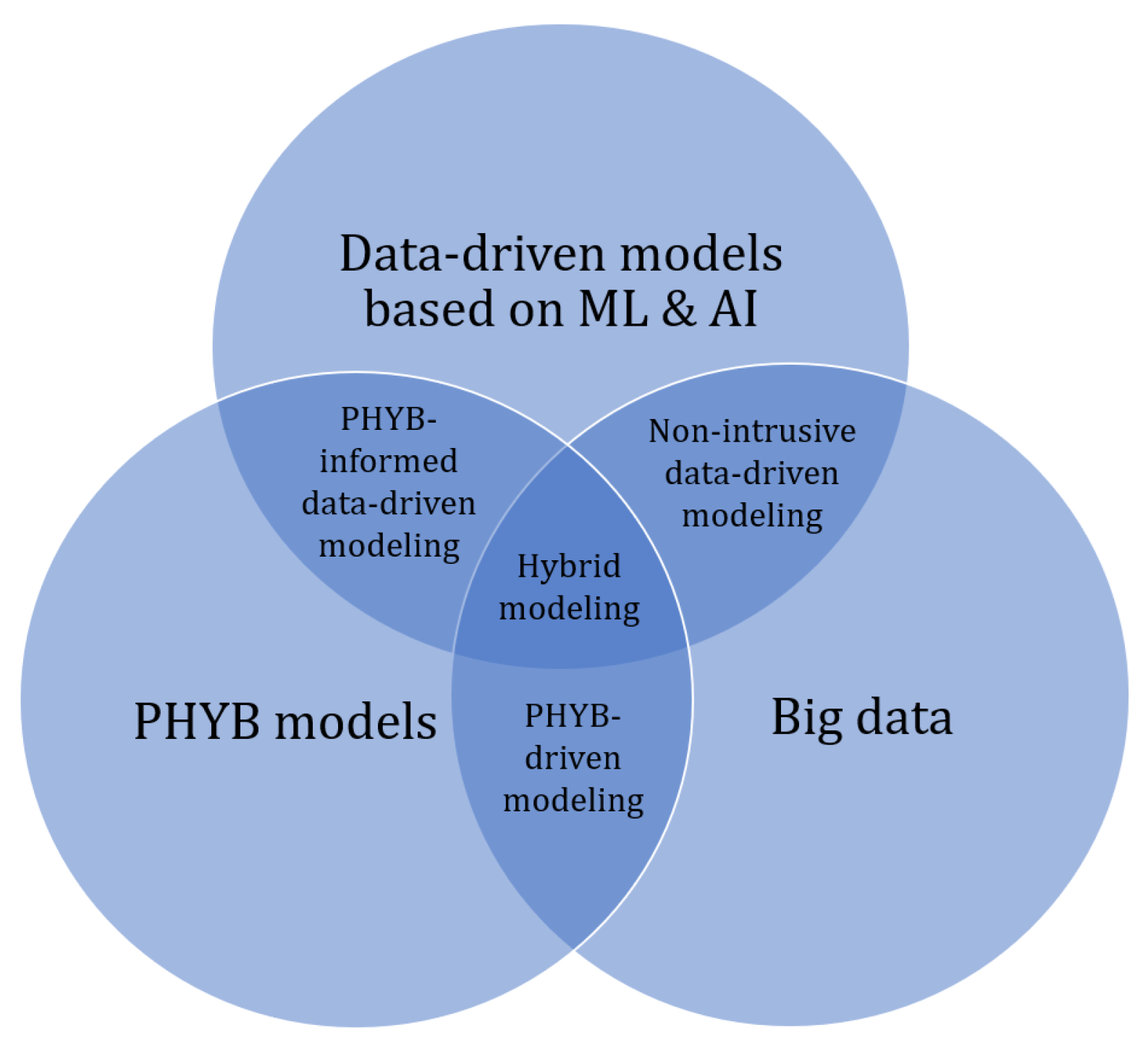
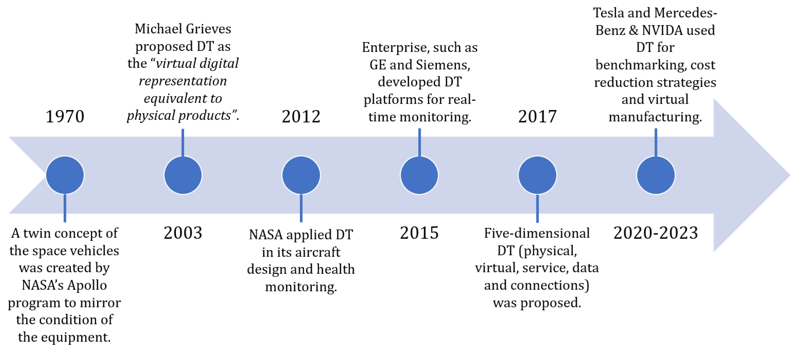
Figure 3.
Scheme of electrical machine DT for intelligent fault diagnosis [4].
Figure 3.
Scheme of electrical machine DT for intelligent fault diagnosis [4].
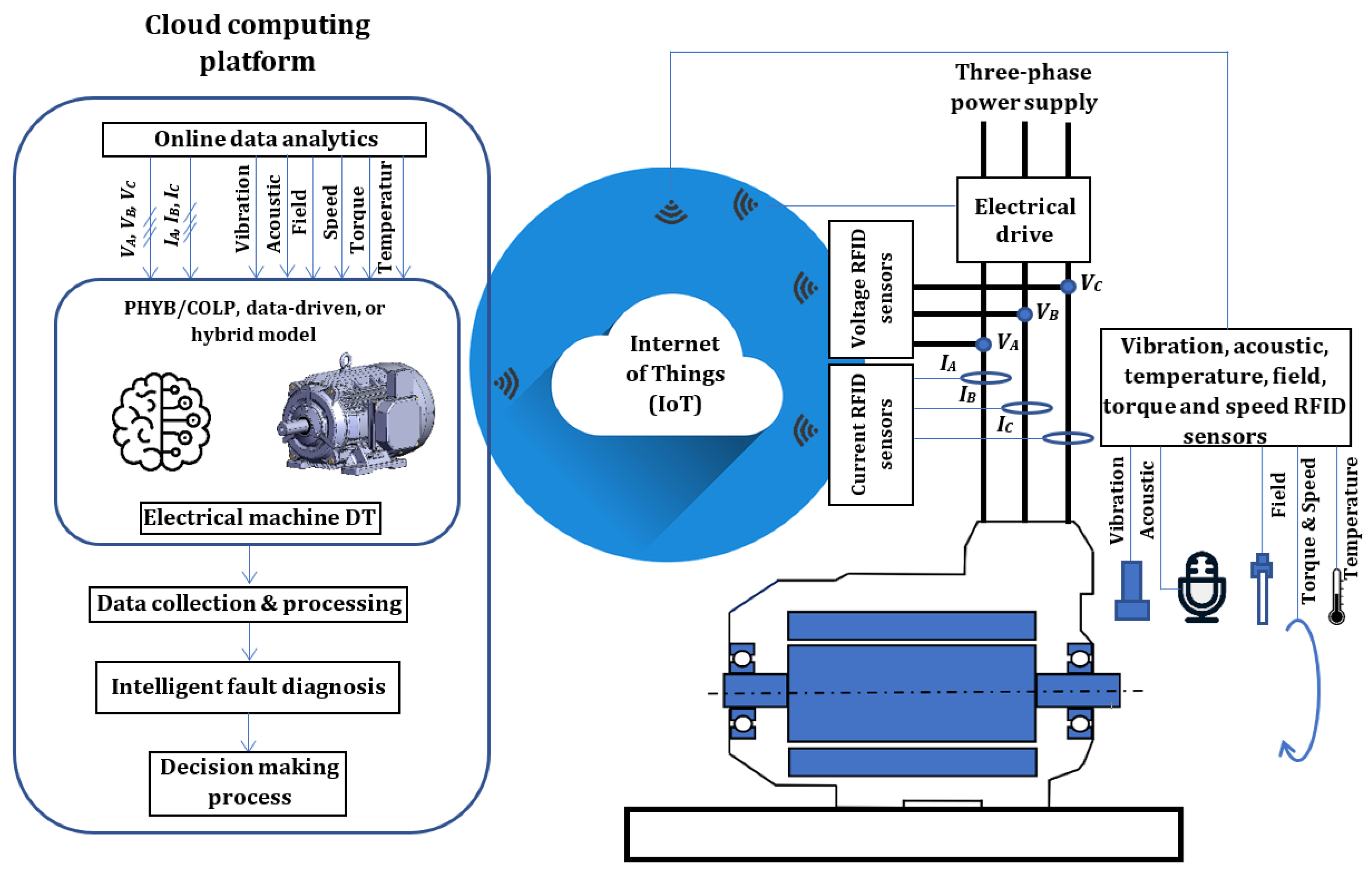
Figure 4.
Stator windings of an IM with an ITSC fault in phase ’a’ [61].
Figure 4.
Stator windings of an IM with an ITSC fault in phase ’a’ [61].
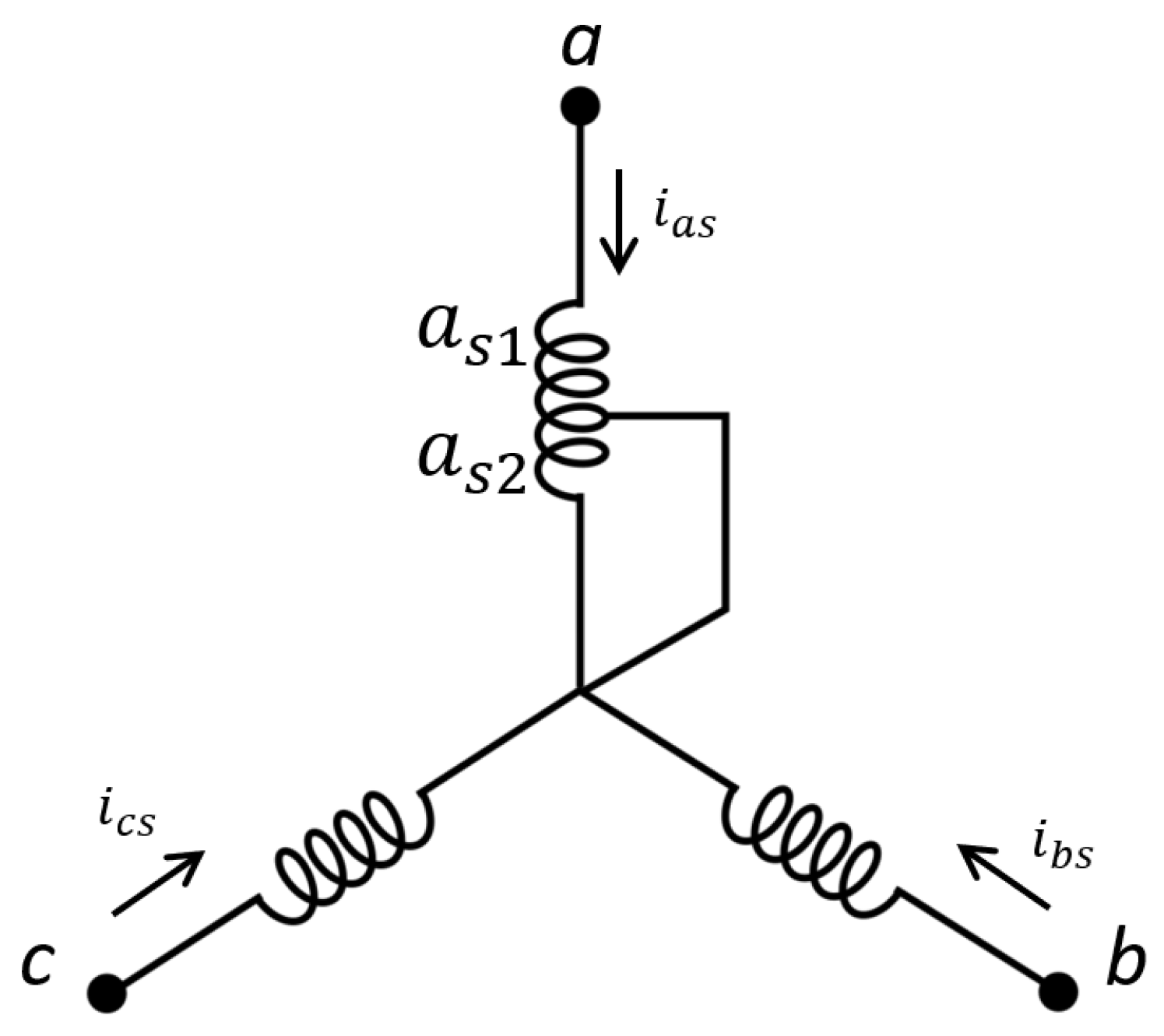
Figure 5.
Equivalent circuit of a squirrel-cage rotor showing rotor loop currents [69].
Figure 5.
Equivalent circuit of a squirrel-cage rotor showing rotor loop currents [69].
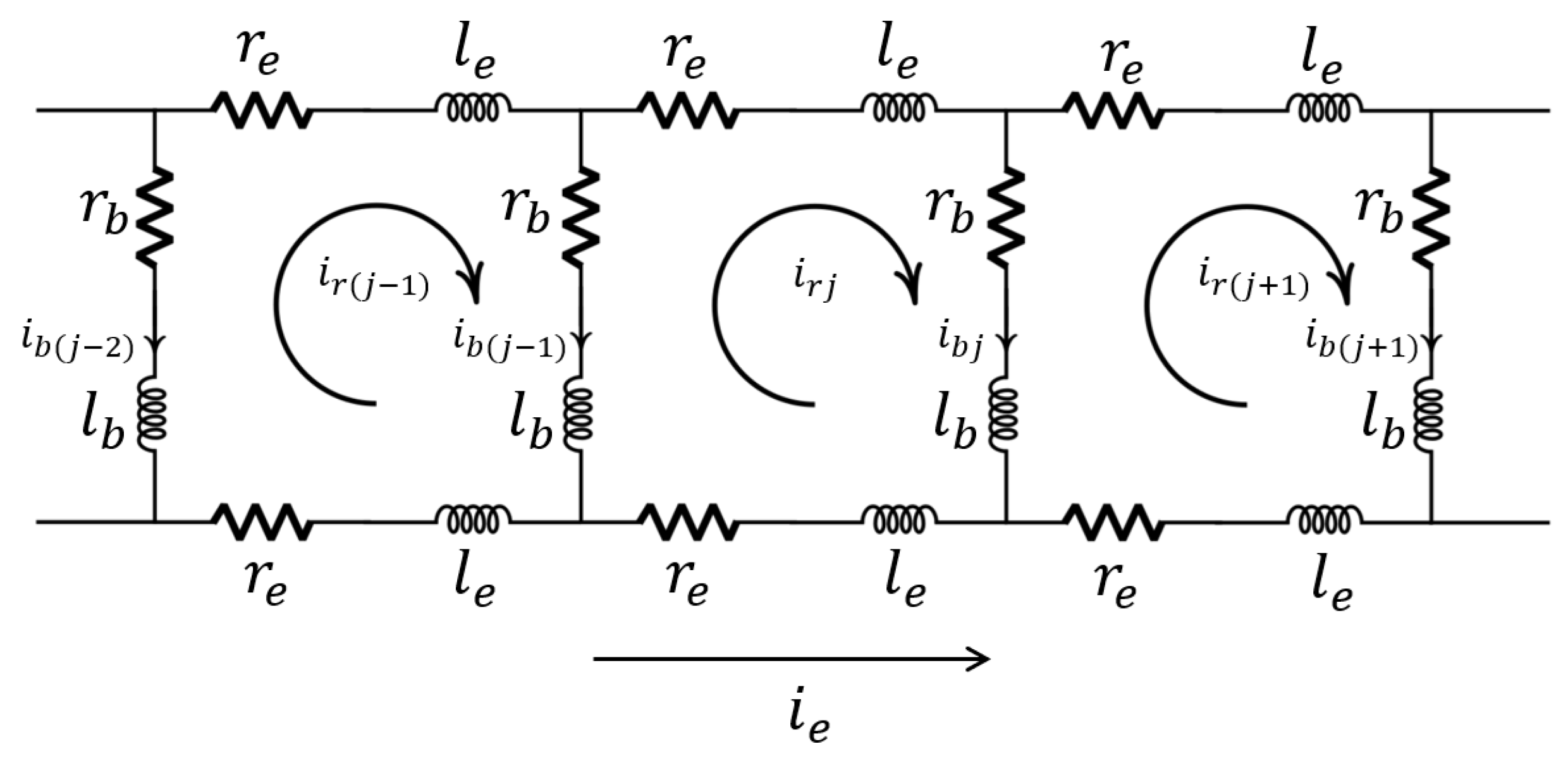
Figure 6.
Scheme of MEC model: (a) 3D reluctance network and, (b) equivalent circuit of each element of the network [4].
Figure 6.
Scheme of MEC model: (a) 3D reluctance network and, (b) equivalent circuit of each element of the network [4].
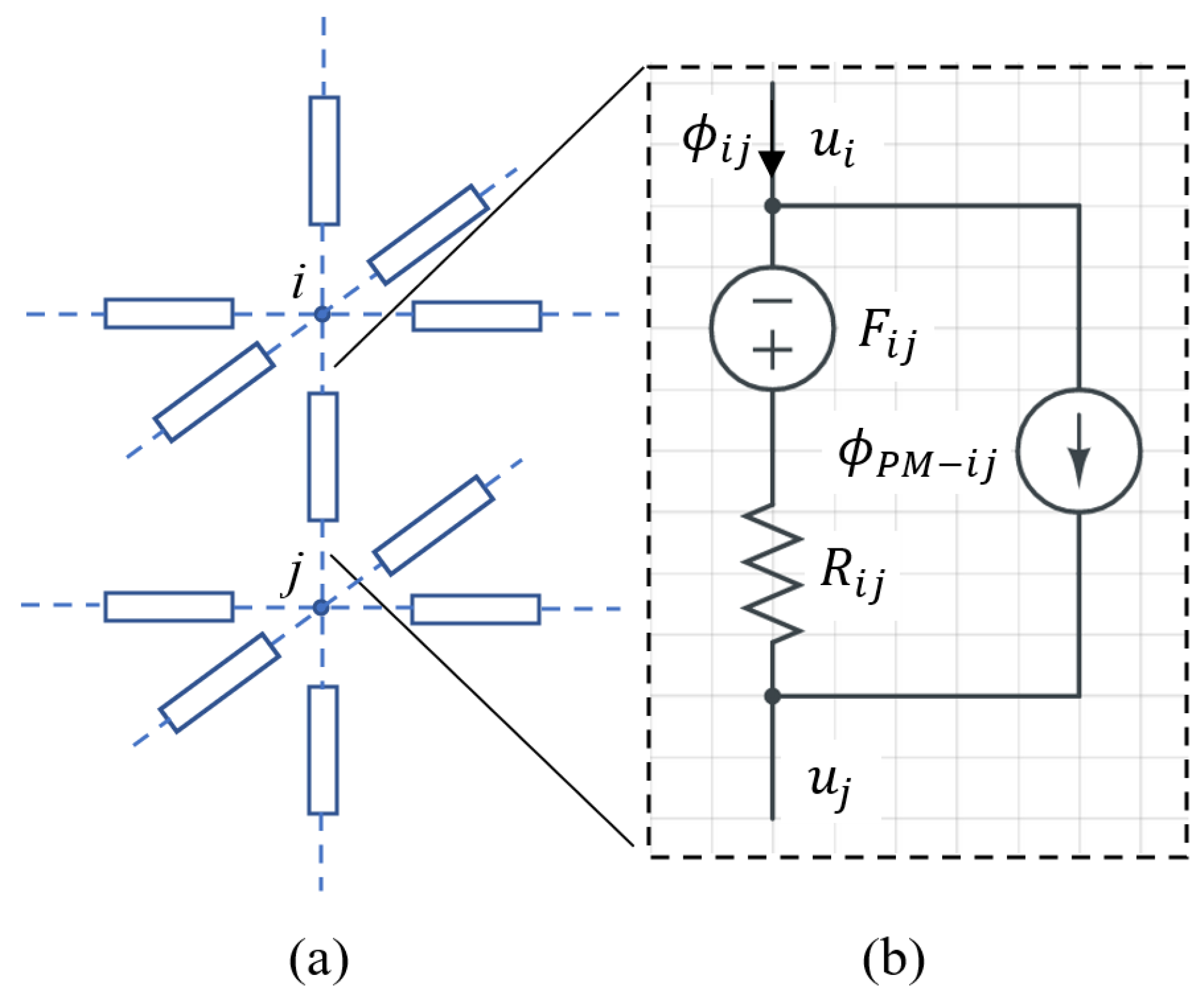
Figure 7.
Schematic of a multiphysics model of an induction machine [141].
Figure 7.
Schematic of a multiphysics model of an induction machine [141].
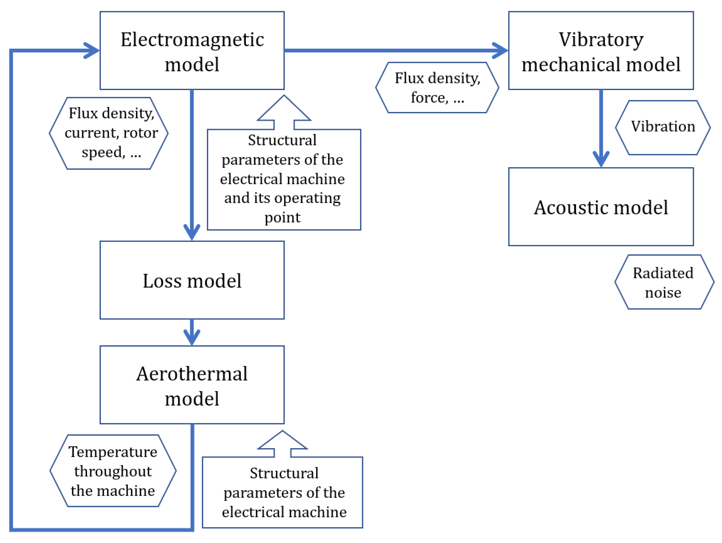
Figure 8.
Integration of the main fault types into the DT of an AC electrical machine.
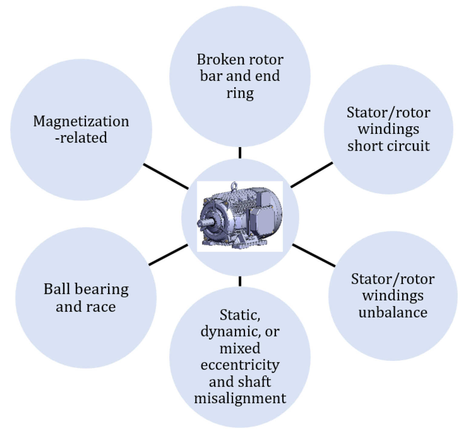
Table 1.
Summery of most popular DT definitions [19].
Table 1.
Summery of most popular DT definitions [19].
| Things | Representation | Data | Purposes | |
|---|---|---|---|---|
| Gartner | Process, physical object, organization, person, or any abstraction | Encapsulated software | Information from several DT can be collected to provide a unified perspective of real-world objects | Simulating an entity in real time |
| NVIDA | Real-world physical things, people, system | Virtual | Information collected from connected sensors, processed through edge computing, enables the replication of physical equipment behavior | Enables the autonomy of systems through the machine learning |
| IBM | Object, system | Virtual | Two-way flow of information | Decision-making based on simulation, machine learning, and reasoning |
| DNV | Asset, system | Virtual | Provide system information through a unified modeling and data solution | Offer guidance for decision-making throughout the asset lifecycle |
| GE Digital | Physical asset, system, process | Software | Real-time analytics | Enhance business outcomes through proactive detection, prevention, prediction, and optimization |
| Siemens | Physical product, process | Virtual | Data is used throughout the product lifecycle to simulate, predict and optimize the product before any prototyping | Undrestand and predict the physical counterpart’s performance characteristics |
| Oracle | Physical asset, device | Digital | Updated with operational data and can be combined with physics-based models | Virtual sensor, detect anomalous behavior and prevent anomalies |
| Microsoft | Object | Digital exact replica | Data from monitoring devices for real-time view of asset | Improve the real-life version |
| Digital twin consortium | Real-world entities and processes | Virtual that is synchronized at a specified frequency and fidelity | Use real-time and historical data to represent the past and present | Transform business, simulate predicted futures |
| Trauer et al. | Physical system | Virtual dynamic | Bidirectional information exchange, and the connection along the entire lifecycle | Improvement of product development by refining requirements, easing troubleshooting, or supporting after sales |
| Grieves, Vickers | Physical manufactured product | Virtual equivalent from the micro atomic level to the macro geometrical level | Link between physical system and its replica | Understanding system behavior |
| Industrial digital twin association | Asset | Digital | Updating throughout the lifecycle based on real-time data | Emulation, simulation, integration, testing, monitoring, and maintenance |
Table 5.
Comparison of PHYB/COLP Modeling Techniques with Data-driven Approaches for Electrical Machines DT Design [7,47].
| PHYB/COLP | Data-driven |
|---|---|
| + Solid foundation in physics | – Black-box concept |
| – Need partial or entire geometric data of the electrical machine | + No need for any knowledge about the electrical machine |
| + No need data for training | – A lot of data needs to be provided for machine learning |
| – Need optimization algorithms for continuous updates of model parameters | + Neural network update |
| – Numerical instability of the model | + Stable for a trained model |
| + Less prone to bias | – Bias in the data can be reflected in the model |
| – Difficult to assimilate extensive historical data | + Integrate easily the extensive historical data |
| + Developed model can be used for similar electrical machines | – New model needs to be trained for each electrical machine |
| + Several variables are available from the developed model | – Only the trained variables are available |
Disclaimer/Publisher’s Note: The statements, opinions and data contained in all publications are solely those of the individual author(s) and contributor(s) and not of MDPI and/or the editor(s). MDPI and/or the editor(s) disclaim responsibility for any injury to people or property resulting from any ideas, methods, instructions or products referred to in the content. |
© 2025 by the authors. Licensee MDPI, Basel, Switzerland. This article is an open access article distributed under the terms and conditions of the Creative Commons Attribution (CC BY) license (http://creativecommons.org/licenses/by/4.0/).
Copyright: This open access article is published under a Creative Commons CC BY 4.0 license, which permit the free download, distribution, and reuse, provided that the author and preprint are cited in any reuse.


