Submitted:
14 July 2025
Posted:
15 July 2025
You are already at the latest version
Abstract
Ensuring the security of wireless electromagnetic communication remains a significant challenge, particularly in environments with limited resources where traditional encryption methods can be impractical. This work introduces a structured, lightweight framework that integrates a nanoantenna-based transformation pipeline with signal-level encryption and error correction in order to enhance physical-layer security. The methodology begins with signal normalisation and quantisation, followed by Hamming error correction. This is then followed by bitwise XOR encryption using a pseudorandom key stream and spatial scrambling via the Arnold transform. Signal reconstruction after nanoantenna filtering and lightweight encryption achieved high accuracy, with RMSE of 7.69×10⁻⁶ and PSNR of 104.27 dB for a Gaussian input. Voice signals also showed strong resilience under distortion. Although the combination of bitwise encryption and the Arnold transform improves obfuscation, the cryptographic strength is limited. These results support the feasibility of the proposed model in low-resource scenarios. Future improvements will focus on secure key generation and hardware implementation.
Keywords:
nanoantenna
; lightweight encryption
; Hamming error correction
; Signal reconstruction
; bitwise XOR encryption
; Arnold transform
1. Introduction
In the recent decades, wireless communication technology has made significant strides, while nanotechnology and nanoscience have captured remarkable attention. These fields have become some of the most compelling areas of modern technology, paving the way for innovative solutions across diverse sectors such as energy, information technology, defense and industry [1].
The 4G mobile system’s era has transformed the way we communicate, bringing a vast array of new features to our fingertips, such as email, text messaging, Wi-Fi connectivity, and even home and car security [2]. Moving forward, 5G technology aims to achieve speeds up to 100 times faster and a 1000 times greater bandwidth to support an expanding array of applications for future devices [2]. The increasing demand for devices that consume large amounts of bandwidth and require higher data rates and lower latency has prompted researchers to begin designing the vision for 6G networks [3].
Among these technological advancements, nanoantennas, also known as optical antennas, emerge as promising and practical structures with the potential to revolutionize wireless communication. Their small size relative to the wavelength of optical signals allows nanoantennas to play a crucial role as signal emitters and receivers [1].
Nowadays, wireless communication has established itself as the dominant framework for modern communication systems, revolutionizing how information is transmitted and received in an increasingly connected world [4]. Alongside with these innovative technologies, the security of the messages and signal transmitted becomes a critical concern. As nanoantennas operate in the optical and electromagnetic domains, they are inherently exposed to potential vulnerabilities such as eavesdropping, signal interception, and unauthorized access. To address these challenges, cryptography emerges as an essential technique to improve security in nano scale communication systems.
This project is therefore framed within this context, focusing on studying the signals transmitted by nanoantennas and their vulnerabilities, as well as investigating and developing cryptographic protocols that effectively integrate with the physical specificities of nanoantennas. The project will evaluate the impact of the proposed cryptographic protocols on the efficiency and performance of communication, taking into account previous studies on cryptography in electromagnetic signals, which have demonstrated significant results.
This paper is structured as follows: Section 2 presents the principles of nanoantennas, approaches security in wireless communication and presents the concept of cryptography and the different kinds of methods to enhance security through cryptography. Section 3 provides a detailed description of the proposed model, covering the signal processing pipeline, the integration of the nanoantenna’s transfer function and the encryption and error correction mechanisms. Section 3 describes the experimental setup and simulation methodology employed to evaluate the system’s performance with both Gaussian and voice input signals. Section 5 presents and analyses the obtained results, focusing on reconstruction accuracy and robustness against distortions. Section 6 discusses the implications of these results, highlighting the framework’s strengths and limitations. Finally, Section 7 draws the main conclusions and outlines directions for future work.
2. Background
2.1. Nanoantennas in Wireless Communications
Antennas are critical components in wireless information transmission technologies, serving as devices that convert electric and magnetic currents into electromagnetic waves, and vice versa [5]. The development of nano-antennas is the result of the emergence of nano-optics, which focuses on the transmission and reception of optical signals at the nanometer level [6]. These antennas, typically made from gold or silver nanoparticles, are designed to resemble traditional Radio-Frequency (RF) antenna structures but operate on a much smaller scale, often much smaller than the wavelength of the incident light [7].
Nanoantennas are based on the principles of electromagnetic theory, described by Maxwell’s equations in their macroscopic and microscopic forms [8]. In 1998, Ebbesen demonstrated that metallic nanostructured arrays exhibited radiation spectra with intensities higher than those predicted by classical theories, describing this phenomena as Extraordinary Optical Transmission (EOT). In the same study, Ebbesen identified Surface Plasmonic Polaritons (SPP) as the primary contributors to this effect [9].
Nanoantennas work by exciting SPP, which are collective oscillations of free electrons at the interface between a metal and a dielectric material when interacting with electromagnetic radiation [9]. When light or any other electromagnetic signal is applied to a nanoantenna, it can be converted into an SPP wave that propagates along the metal-dielectric interface before being lost due to absorption in the metal or radiation into free space, as shown in Figure 1.
In a material with permittivity , permeability , and no external sources, the behavior of electromagnetic waves can be described by the wave equation for the electric field [11]:
where is the Laplace operator, representing the spatial variation of the field, is the electric field vector, is the permittivity of the material, c is the speed of light in vacuum and is the second partial derivative of the electric field with respect to time [11].
The efficiency of this conversion depends directly on the resonant frequency of the nanoantenna and its geometric properties, including size, shape and material composition [12].
The excitation of SPP requires a matching of the wave vector of the incident electromagnetic wave to that of the plasmonic wave [12]. This matching condition is governed by the dispersion relation of spp at the metal-dielectric interface.
For a metal-dielectric interface, the dispersion relation of the SPPs is given by the equation(2):
where is the wave vector of the surface plasmon, is the angular frequency of the incident light, c is the speed of light in vacuum, is the permittivity of the metal, and is the permittivity of the dielectric [12].
The amplification phenomenon occurs because SPP generate highly localized electric and magnetic fields with energy densities much higher than that of the incident field [13]. The concentration of this energy at the nanoscale leads to an increase in the intensity of the transmitted signal, which is particularly useful in applications requiring signal transmission or processing over very short distances or at nanoscale dimensions [13].
Field enhancement by SPP is a key feature exploited in plasmonic applications, enabling efficient energy transfer [14]. This phenomenon can be described by the field distribution in the near-field region of the surface plasmon. The field near the surface of a thin metal film can be approximated as in equation (3):
where is the electric field, is the field amplitude at the surface, is the decay constant in the dielectric, and x and z are the spatial coordinates along the interface and perpendicular to the surface, respectively [14].
The interaction of light with nanoantennas can be tuned to amplify signals at specific frequencies [7]. This frequency-selective amplification is a powerful feature for communications applications, where frequency modulation is essential for data encoding and transmission [7]. By controlling the plasmonic resonance of the nanoantennas, it is possible to amplify signals at specific wavelengths, enabling higher bandwidth and more efficient communication networks. This capability makes nanoantennas particularly promising for use in high-capacity communication networks where signal amplification and wavelength tuning are critical [7]. This amplification goes beyond simply increasing signal intensity as it can also involve manipulation of other signal properties such as phase and polarization.
2.2. Security in Wireless Communication
As wireless technologies become increasingly integrated into a wide range of activities, including personal communications and vital industrial operations, the security of these networks becomes a critical concern [16]. In this context, there are areas that are of particular importance including the Physical Layer Security (PLS) approaches, the identification of threats and vulnerabilities specific to wireless networks and antenna-based security measures.
2.2.1. Physical Layer Security
PLS can be defined as an advanced security approach that enhances the confidentiality of wireless communications by exploiting the physical characteristics of the communication channel. The concept of PLS was first mathematically defined in the 1970s through the model of a wiretap channel [17]. A typical PLS network comprises three primary components: a transmitter, a legitimate receiver, and an eavesdropper. In such a network, the transmitter, known as "Alice," transmits a confidential message to the receiver, known as "Bob." This transmission is safeguarded against any interception attempts by the eavesdropper, referred to as "Eve", as it is shown in Figure 3 [18].
The techniques employed in PLS encompass beamforming, whereby signals are directed with precision to the legitimate user, and artificial noise generation, whereby noise is intentionally introduced to the eavesdropper’s channel without affecting the primary communication link. These techniques leverage advanced signal processing and adaptive modulation methods to dynamically adjust to the conditions of the transmission medium and the positioning of unauthorized interceptors [19].
3. Related Work
3.1. Electromagnetic Analysis for Cryptography
The author Gunathilake and his collaborators in [20], established the importance of lightweight cryptography in Internet of Things devices, which are limited by their processing power, memory, and energy consumption. This study posits the vulnerability of these devices to side-channel attacks due to physical leakages. It introduces the cipher "PRESENT" as a potential solution, with its small block and key sizes designed for efficiency in constrained environments [20].
The EM emissions from the PRESENT cipher are analyzed to assess its vulnerability to side-channel attacks, specifically through electromagnetic analysis. The author delineates the methodological framework and the practical implementation of capturing electromagnetic emissions from the cipher during its operation to detect potential data leakages. Through the use of mathematical models, Hamming weight and distance, to hypothesize potential information leakage and conducting two types of EM analysis such as Simple Electromagnetic Analysis and Correlation Electromagnetic Analysis in the time and frequency domain obtained that EM analysis can effectively identify potential leakages in cryptographic implementations like the PRESENT cipher [20].
The observations encompass variations in the electromagnetic field strength during distinct cipher operations, which may be indicative of varying internal states of the cipher [20]. Moreover, the observations accentuate particular instances where the EM emissions exhibited a robust correlation with theoretical predictions of data leakage, thereby suggesting the potential for the extraction of sensitive information [20].
3.2. Knapsack Encryption with Elliptic Curve Cryptography (ECC) Based Secured Wireless Network
The study by Arun [21] combined ECC algorithm to the Knapsack encryption algorithm. The knapsack algorithm is a type of public key algorithm that falls under the subset-sum problem category, where the goal is to find a subset of numbers that adds up to a given sum. This numbers can represent the weights of items to be packed in a "knapsack". This approach aims to leverage the strengths of both methods as ECC’s efficient key management and the knapsack’s ability to handle large data sets efficiently.
The model initially implements the Knapsack algorithm to encrypt the data intended for transmission. The Knapsack algorithm is further encrypted using ECC, adding an additional layer of security and further obfuscating the data from potential interceptors. The encrypted data is then transmitted across the network via intermediate nodes. The encryption is robust enough to prevent unauthorized access, even if the transmission path is compromised. At the receiver’s end, the data is first decrypted using the private ECC key, and then the inverse process of the knapsack algorithm is employed to reconstruct the original plaintext from the encrypted message.
The method proposed by the authors is evaluated using several performance metrics, such as security enhancement by comparing the model to a single ECC implementation. The results showed that ECC algorithm obtained 80% of security based on the node, as the model proposed combining the Knapsack algorithm and ECC has obtained a very high level of security of 98%. According to the authors [21], this mechanism avoids attacks like Man-in-the-Middle in military applications.
3.3. Elevating Security Using ECC and Advanced Encryption Standard (AES) Algorithms
ECC is a notable instrument in the repertoire of cryptographic techniques suitable for wireless sensor networks. Fundamentally, ECC utilizes the algebraic properties of elliptic curves over finite fields to offer robust security with relatively brief key lengths [22]. The AES is a foundational component in the field of symmetric-key encryption, playing a pivotal role in ensuring the security of data across a wide range of domains. In contrast to ECC, AES utilizes a shared secret key for both the encryption and decryption processes, thereby enhancing computational efficiency [22].
Dayana et al. [22] proposed a system that combines both cryptographic techniques. In this system, ECC generates a pair of keys a private key and a public key. For symmetric encryption, an AES key was generated. The model was tested by firstly encrypt the "Sample" data using AES. After the first step, an ECC signature is then generated using the private key and the concatenated message of the "Sample" data and the AES encrypted data, to ensure both the integrity and authenticity of the data. Upon receiving the encrypted data, the recipient separates the AES encrypted data and ECC signature. The ECC signature is verified using the ECC public key, and if valid the AES algorithm will decrypt data to retrieve the original data.
The results of the model proposed by Dayana and his collaborators achieved an Authentication Success Rate of 96% , outperforming ECC and AES separately. Another metric of performance evaluated was the Data Confidentiality Verification Rate, in which the method of ECC+AES obtained a very high effectiveness as shown in Figure 4.
4. Proposed Model
In this work, we propose a multi-stage framework aimed at enhancing the security of wireless communications by leveraging nanoantenna technology combined with cryptographic techniques. The proposed system architecture is composed of five sequential blocks, each contributing to the secure transmission and reconstruction of the electromagnetic signal:
-
Block 1 – Nanoantenna Response Characterization:The process initiates with the design and full-wave modeling of a nanoantenna, developed from fundamental principles. The structure will be used to amplify the signal transmitted.
-
Block 2 – Signal Quantization and Error Correction:The electromagnetic response at the output of the nanoantenna is captured, normalized, and quantized, resulting in a digital bitstream. Subsequently, the stream undergoes processing by an error correction module that is based on Hamming (8,12) coding. This coding provides resilience against transmission errors.
-
Block 3 – Pseudo-Random Key Generation and Bitwise Encryption:A pseudo-random key is generated, and a bitwise encryption is performed using the XOR operation, ensuring basic confidentiality and resistance to statistical attacks.
-
Block 4 – Arnold Transform Encryption:In order to achieve enhanced cryptographic robustness, the encrypted bitstream undergoes an Arnold Transform, thereby introducing an additional layer of security based on permutations.
-
Block 5 – Signal Recovery at the Receiver:The receiver module is responsible for implementing the inverse operations, with the objective of recovering and reconstructing the original signal. This process is integral to the completion of the secure communication process from end to end.
4.1. Block 1 – Nanoantenna Response Characterization
The nanoantenna concept outlined in this study was developed and simulated. The structure consists of a rectangular metallic film made of gold (Au) deposited on a dielectric substrate and patterned with a periodic square array of sub-wavelength apertures. The thickness of the dielectric and metallic layers is 100 nm.
The array,as shown in Figure 5 , is composed of square apertures, each with side length , where corresponds to the central design wavelength. The apertures are spaced by the same distance () in both x and z directions, ensuring periodicity and enabling strong surface plasmon polariton (SPP) excitation. The total length of the nanoantenna structure is .
The nanoantenna block is designed to amplify the signal to be transmitted. Prior to integration into the communication pipeline, a detailed electromagnetic analysis is conducted to evaluate the spatial distribution of the electric field on a predefined observation plane. The aim of this evaluation is to identify the precise spatial location at which the electric field exhibits its maximum amplitude response and the frequency at which this peak occurs.
By isolating this optimal point, which corresponds to the maximum local field enhancement, it becomes possible to characterize the nanoantenna’s behaviour with high fidelity. In particular, the transfer function of the antenna is computed exclusively at this spatial location, thereby capturing the frequency-dependent transformation that an input signal undergoes as it propagates through the nanoantenna.
Following this amplification and transfer function evaluation, the output signal at the selected point is subjected to a normalization and quantization process.
In order to facilitate comprehension of the proposed structural design, please refer to Table 1, which delineates the parameters that have been stipulated to guide the conceptualization and design of the nanoantenna.
4.2. Block 2 – Signal Quantization and Error Correction
Subsequent to the normalization of the output signal to the interval of [0, 1], the signal undergoes uniform quantization into 16-bit unsigned integers, and each sample is converted to its binary representation. The resulting bitstream is then segmented into blocks of 8 bits, which are encoded using a Hamming (8,12) error correction code. This process appends four parity bits to each block at positions corresponding to powers of two (1, 2, 4, 8), thereby enabling single-bit error detection and correction. The parity bits are computed using modulo-2 sums over predefined subsets of the data bits, ensuring compliance with the Hamming parity-check conditions. This encoded bitstream serves as the foundation for subsequent secure transmission.
4.3. Block 3 – Pseudo-Random Key Generation and Bitwise Encryption
The encryption mechanism implemented in this system is based on a symmetric bitwise XOR operation applied over the Hamming-encoded bitstream. To generate the binary key stream required for this operation, a pseudo-random number generator (PRNG) is seeded with a fixed private integer key, denoted . In the current implementation, this key is statically defined, , and acts as the shared secret between the transmitter and receiver.
The PRNG is initialized using MATLAB’s rng() function, which sets the internal state of the random number generator in a deterministic way based on . Once seeded, the function randi([0,1], N, N) is used to produce a matrix of binary values representing the key stream, where N is the dimension of the square bit matrix resulting from the encoded signal. This matrix, , contains independent and identically distributed (i.i.d.) binary elements generated uniformly at random under the fixed seed:
The Hamming-encoded bitstream is first padded with zeros and reshaped into a square matrix . The encryption process consists of computing the element-wise XOR between and the key stream matrix :
where ⊕ denotes the bitwise exclusive XOR operation.
This transformation ensures that each bit of the encoded message is masked by a corresponding pseudo-random bit, producing the encrypted matrix .
Because the key stream is generated deterministically from a fixed seed, the exact same sequence can be reproduced at the receiver by reapplying rng(). The XOR operation is symmetric and invertible, meaning that decryption is performed by reapplying XOR with the same key stream:
4.4. Block 4 – Arnold Transform Encryption
Following the encryption process, the bitstream matrix is subjected to further obfuscation through the implementation of the Arnold transform. This transform is a two-dimensional, area-preserving mapping that manipulates the order of matrix elements in accordance with a chaotic yet deterministic rule.
Originally defined for image scrambling, the Arnold Transform is applied here to the encrypted binary matrix to disrupt spatial regularities and introduce an additional layer of security.
For a matrix of size , each bit located at coordinates is mapped to a new position given by the discrete linear transformation:
This mapping is invertible and periodic, meaning that after a finite number of iterations, the original matrix is fully recovered. The number of iterations used, denoted , acts as an additional key parameter in the system, and must be known to perform correct decryption.
4.5. Block 5 – Signal Recovery at the Receiver
On the receiver side, the decryption process is the exact inverse of the bitwise encryption described previously. To reconstruct the original Hamming-encoded bitstream, the pseudo-random key stream must be regenerated identically. This is achieved by initializing the same pseudo-random number generator (PRNG) with the known shared key using the rng() function.
The PRNG is seeded with the same integer:
which ensures that the internal state of the generator is synchronized with that used at the transmitter. The identical binary key stream is then regenerated using:
Given the received encrypted matrix , the decryption is performed by computing the element-wise XOR with the key stream:
This operation is valid due to the involutive property of XOR, allowing full recovery of the original encoded bit matrix .
After decryption, the matrix is vectorized and truncated to remove any padding bits added prior to encryption. The resulting bitstream is then passed to the Hamming decoder to detect and correct any residual single-bit errors introduced during transmission. Once decoding is complete, the corrected bitstream is reassembled into 16-bit integers and denormalized to reconstruct the original analog signal.
5. Results
The initial objective was to ascertain the spatial point at which the electric field attains its maximum amplitude, as this location is considered the most indicative of the nanoantenna’s peak electromagnetic response.
To identify the point of maximum electric field intensity, a frequency sweep ranging from 0.1 to 3 THz was conducted. For each frequency, the total field amplitude was reconstructed from the complex components , , and .
The maximum value across all frequencies was identified, and the corresponding spatial coordinates were extracted, as shown in Figure 6. This particular point, where the electric field reaches its maximum, was selected for subsequent transfer function analysis. This selection was made on the basis that it represents the location of the most significant field enhancement near the nanoantenna.
Subsequent to the identification of the point of maximum electric field intensity, it was necessary to characterize the nanoantenna’s frequency response at that specific location.
This objective was accomplished by calculating the transfer function, which is defined as the projection of the complex electric field vector onto the direction of the incident wave, across the frequency range of interest. The resulting complex response was then normalized and decomposed into magnitude and phase components.
In order to facilitate its use in analytical models, the transfer function was fitted to a parametric expression as follows:
The magnitude was approximated by an exponential decay function, while the phase followed a linear trend. This approach allowed the extraction of key parameters such as group delay that corresponds to .
5.1. Nanoantenna Response to Signals
After obtaining the transfer function , the temporal response of the nanoantenna to incident signals was investigated.
As an initial test case, a Gaussian pulse was selected due to its simplicity and well-defined spectral content. The input signal was transformed into the frequency domain via FFT, and the previously computed at the point of maximum response was applied as a frequency-domain filter. The resulting spectrum was then transformed back to the time domain using IFFT, allowing observation in Figure 7 of the antenna-induced distortion on the temporal waveform. This procedure validated the expected system behavior and served as a foundation for future analysis involving more complex signal structures.
After the initial validation using a Gaussian pulse, we proceeded to evaluate the response of the nanoantenna to a more realistic and complex signal. This signal was generated as amplitude-modulated white noise to emulate the spectral and temporal dynamics of human speech.
By mapping the audio frequencies into the antenna’s operating band and applying the transfer function in the frequency domain, was obtained the output signal corresponding to the antenna’s response, as shown in Figure 8.
The result, converted back to the time domain, provided insight into the distortion and filtering effects induced by the nanoantenna when processing real-world signals.
5.2. Proposed Cryptography Model Test
After analyzing the antenna’s impulse response to a Gaussian pulse, a comprehensive encryption and decryption pipeline for the output signal was developed, incorporating the previously proposed model. The system was evaluated under a series of conditions. In the first condition, Figure 9, the system was subjected to an ideal environment devoid of noise or interference. The results were as expected, showing a correlation between the original signal and the recovered signal of 1.00, RMSE of and PSNR of 104.27 dB
In the second condition, Figure 10, the system was exposed to an environment with noise levels of 0.2 V/m. The results obtained a correlation between the original signal and the recovered signal of 0.7507, RMSE of and PSNR of 20.70 dB.
In the third condition, Figure 11, the receiver was unable to access the key, which hindered the successful retrieval of the signal. The results obtained a correlation between the original signal and the recovered signal of 0.0118, RMSE of and PSNR of 5.78 dB.
Following the validation of the encryption and recovery mechanisms with a Gaussian test pulse, the analysis was expanded to a more complex and realistic scenario through the application of the full pipeline to a synthetic voice signal.
The resulting output signal was then subjected to various degradation scenarios, such as additive white Gaussian noise (AWGN), Multipath Propagation, quantization, echo.
In a scenario where the original signal is distorted by Gaussian white noise with an SNR of 20 dB, the results shown in Figure 12, show a correlation between the original signal and the recovered signal of 0.99504, RMSE of 0.12914, and PSNR of 35.527 dB.
The next scenario involved signal reflections, or ’Multipath’, as found in urban environments. This produces echoes with different delays and successive attenuations. The results shown in Figure 13, show a correlation between the original signal and the recovered signal of 0.25789, RMSE of 1.6329, and PSNR of 13.489 dB.
Next, the loss of resolution in an analogue-to-digital converter (ADC) was simulated. This type of distortion is common in systems with low digitisation accuracy. The results shown in Figure 14, show a correlation between the original signal and the recovered signal of 0.99991, RMSE of 0.017303, and PSNR of 52.986 dB.
Final scenario simulated was electromagnetic echo, very common in voice calls without echo cancellation. A delayed echo of 30 ms was added to the original signal with 60 % of the amplitude. The results shown in Figure 15, show a correlation between the original signal and the recovered signal of 0.85855, RMSE of 0.77097, and PSNR of 20.008 dB.
As a sum up of all results, Table 2 shows all the results obtained in each scenario.
6. Discussion
The results presented in Table 2 support the conclusion that the proposed model, which combines bit-level manipulation with the Arnold transform, effectively protects signal integrity in most test scenarios.
The pipeline maintained high correlation and PSNR values in the presence of additive white Gaussian noise (AWGN), quantization and echo effects, demonstrating its robustness to the common distortions encountered in realistic communication channels.
However, using a fixed key and a non-cryptographically secure PRNG introduces vulnerabilities, which are particularly evident when an incorrect key is used. For example, in the case of a Gaussian signal under a wrong-key attack, the correlation dropped drastically to 0.0118 and the PSNR plummeted to 5.78 dB. This severe degradation confirms that the system is intolerant of key mismatches, which could be considered a security feature, but it also highlights the need for a more robust key management strategy.
Notably, the Arnold Transform alone does not offer robust cryptographic security. Its role as a spatial scrambler is to obscure recognizable patterns, especially in structured signals, but it does not increase true entropy. When used with a predictable or static key stream, it is vulnerable to chosen-plaintext or known-plaintext attacks. This suggests that, while the system is efficient and suitable for constrained environments, it should be enhanced for deployment in adversarial conditions.
Despite these limitations, the method shows promising results for practical applications where performance and simplicity are prioritized over military-grade security. In particular, the high PSNR values achieved in the ideal and quantized scenarios (104.27 dB and 52.98 dB, respectively) confirm that the encryption–decryption process preserves signal quality without significant distortion.
7. Conclusions
This work presents a comprehensive, lightweight encryption pipeline for protecting electromagnetic signals. It combines amplitude normalization, bit-level transformation, modular encryption and spatial scrambling via the Arnold transform. This methodology was validated using synthetic (Gaussian) and realistic (voice) signals under various distortion scenarios, including noise, quantization, multipath and echo.
However, a security analysis revealed that the current implementation is vulnerable to key inference and is not robust enough to withstand cryptographic attacks, such as chosen-plaintext analysis. These limitations stem from the use of a static key and a non-secure pseudorandom number generator.
As future work, several improvements are planned:
- Replace the current key scheduling mechanism with a dynamic key exchange system based on elliptic curve Diffie–Hellman (ECDH).
- Integrate a cryptographically secure pseudorandom number generator to enhance unpredictability.
- Extend the analysis to other classes of signals, including video or biomedical data.
- Evaluate resilience under active adversarial models and simulate attack scenarios.
Funding
This research received no external funding.
Conflicts of Interest
The authors declare no conflicts of interest.
Abbreviations
The following abbreviations are used in this manuscript:
| AES | Advanced Encryption Standard |
| AWGN | Additive White Gaussian Noise |
| ECC | Elliptic Curve Cryptography |
| ECDH | Elliptic Curve Diffie–Hellman |
| EM | Electromagnetic |
| EOT | Extraordinary Optical Transmission |
| FFT | Fast Fourier Transform |
| IFFT | Inverse Fast Fourier Transform |
| LSPR | Localized Surface Plasmon Resonance |
| PEC | Perfect Electric Conductor |
| PLS | Physical Layer Security |
| PSNR | Peak Signal-to-Noise Ratio |
| RF | Radio-Frequency |
| RMSE | Root Mean Square Error |
| SPP | Surface Plasmonic Polaritons |
References
- Gomes, R.D.F.R.; Martins, M.J.; Baptista, A.; Torres, J.P.N. Study of a nano optical antenna for intersatellite communications. Optical and Quantum Electronics 2017, 49, 1–22. [Google Scholar] [CrossRef]
- Rawat, B.S.; Bhat, A.; Pištora, J. THz band nanoantennas for future mobile communication. In Proceedings of the 2013 International Conference on Signal Processing and Communication (ICSC). IEEE; 2013; pp. 48–52. [Google Scholar]
- Alves, A.; Melo, M.C.; Siqueira, J.; Zanella, F.; Mejía-Salazar, J.R.; Arismar, C.S. Plasmonic nanoantennas for 6G intra/inter-chip optical-wireless communications. In Proceedings of the 2020 2nd 6G wireless summit (6G SUMMIT). IEEE; 2020; pp. 1–4. [Google Scholar]
- Wu, Q. 4g communication technology wireless network secure communication. In Proceedings of the 2021 International Wireless Communications and Mobile Computing (IWCMC). IEEE; 2021; pp. 915–918. [Google Scholar]
- Balanis, C.A. Antenna theory: A review. Proceedings of the IEEE 1992, 80, 7–23. [Google Scholar] [CrossRef]
- Kavankova, I.; Kovar, S.; Valouch, J.; Adamek, M. Review of nanoantennas application. Prz. Elektrotechniczny 2023, 1, 13–17. [Google Scholar] [CrossRef]
- Maksymov, I.S. Magneto-plasmonic nanoantennas: Basics and applications. Reviews in Physics 2016, 1, 36–51. [Google Scholar] [CrossRef]
- Fakhimi, M.J.; Akan, O.B. Nanoantennas and Nanoradars: The Future of Integrated Sensing and Communication at the Nanoscale. IEEE Transactions on Molecular, Biological, and Multi-Scale Communications 2024, 10, 493–516. [Google Scholar] [CrossRef]
- Ebbesen, T.; Lezec, H.; Ghaemi, H.; Thio, T.; Wolff, P. Extraordinary Optical Transmission Through Sub-Wavelength Hole Arrays. Nature 1998, 391, 667–669. [Google Scholar] [CrossRef]
- Wen, J. Excitation and detection of highly confined plasmonic gap modes with subwavelength dimensions; Friedrich-Alexander-Universitaet Erlangen-Nuernberg (Germany), 2011.
- Maier, S.A.; et al. Plasmonics: fundamentals and applications; Vol. 1, Springer, 2007.
- Raether, H.; et al. Surface Plasmons on Smooth and Rough Surfaces and on Gratings [electronic resource].
- Piltan, S.; Sievenpiper, D. Field enhancement in plasmonic nanostructures. Journal of Optics 2018, 20, 055401. [Google Scholar] [CrossRef]
- Geshev, P.; Klein, S.; Witting, T.; Dickmann, K.; Hietschold, M. Calculation of the electric-field enhancement at nanoparticles of arbitrary shape in close proximity to a metallic surface. Physical Review B (Condensed Matter and Materials Physics) 2004, 70, 75402. [Google Scholar] [CrossRef]
- Bhattarai, J.; Maruf, H.U.; Stine, K. Plasmonic-Active Nanostructured Thin Films. Processes 2020, 8, 115. [Google Scholar] [CrossRef]
- Anitha, G.; Nirmala, P.; Ramesh, S.; Tamilselvi, M.; Ramkumar, G. A Novel Data Communication with Security Enhancement using Threat Management Scheme over Wireless Mobile Networks. In Proceedings of the 2022 International Conference on Advances in Computing, Communication and Applied Informatics (ACCAI). IEEE; 2022; pp. 1–6. [Google Scholar]
- Bassily, R.; Ekrem, E.; He, X.; Tekin, E.; Xie, J.; Bloch, M.R.; Ulukus, S.; Yener, A. Cooperative Security at the Physical Layer: A Summary of Recent Advances. IEEE Signal Processing Magazine 2013, 30, 16–28. [Google Scholar] [CrossRef]
- Sanenga, A.; Mapunda, G.A.; Jacob, T.M.L.; Marata, L.; Basutli, B.; Chuma, J.M. An overview of key technologies in physical layer security. Entropy 2020, 22, 1261. [Google Scholar] [CrossRef] [PubMed]
- Hoseini, S.A.; Bouhafs, F.; den Hartog, F. A practical implementation of physical layer security in wireless networks. In Proceedings of the 2022 IEEE 19th Annual Consumer Communications & Networking Conference (CCNC). IEEE; 2022; pp. 1–4. [Google Scholar]
- Gunathilake, N.A.; Al-Dubai, A.; Buchanan, W.J.; Lo, O. Electromagnetic analysis of an ultra-lightweight cipher: Present. arXiv preprint arXiv:2106.15225, 2021; arXiv:2106.15225. [Google Scholar]
- Arun, V.; Kuppusamy, P.; Naveen, G.; Santhuja, P. Knapsack Encryption with Elliptic Curve Cryptography Based Secured Wireless Network. In Proceedings of the 2023 2nd International Conference on Edge Computing and Applications (ICECAA); 2023; pp. 298–302. [Google Scholar] [CrossRef]
- Dayana, D.S.; Pandian, R.; Babu, A.R.; Nirmalraj, S.; Jebaseelan, S.D.S.; V, M. Elevating Security in Wireless Sensor Networks using ECC and AES Cryptographic Techniques. In Proceedings of the 2023 International Conference on Innovative Computing, Intelligent Communication and Smart Electrical Systems (ICSES); 2023; pp. 1–6. [Google Scholar] [CrossRef]
Figure 1.
SPP with propagation vector between a metal and a dielectric material have a combined electromagnetic wave and surface charge character [10].
Figure 1.
SPP with propagation vector between a metal and a dielectric material have a combined electromagnetic wave and surface charge character [10].
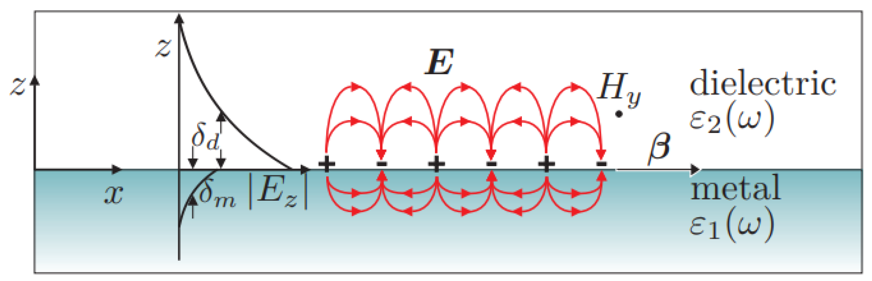
Figure 2.
Schematic diagrams illustrating the excitation of surface plasmons: (a) excitation from a thin film using a prism as a coupling device, generating a SPP, and (b) excitation from a nanoparticle, generating a Localized Surface Plasmon Resonance (LSPR). The typical spectra resulting from surface plasmon excitation are shown on the right [15].
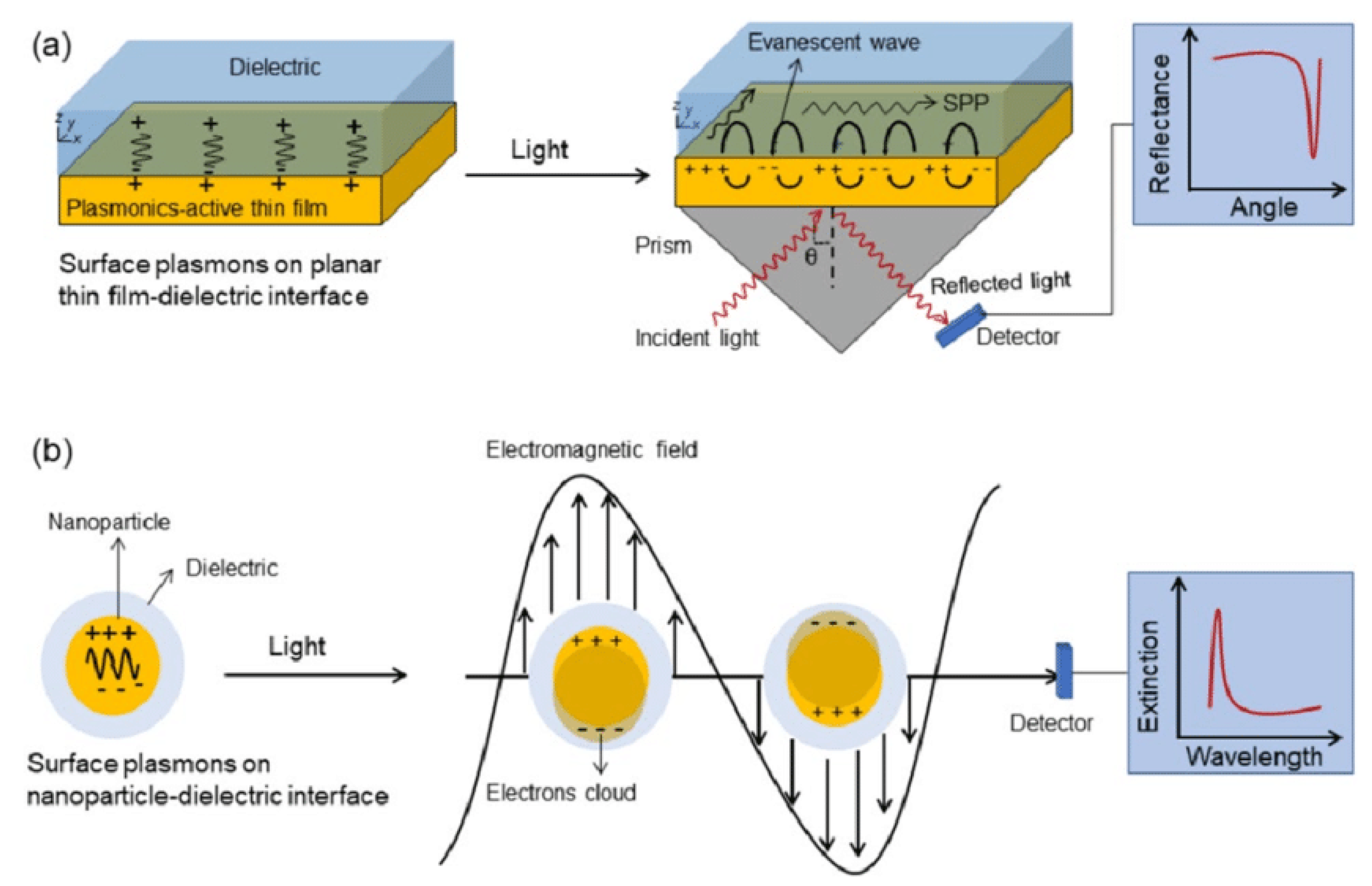
Figure 3.
Wiretap channel [18].
Figure 3.
Wiretap channel [18].
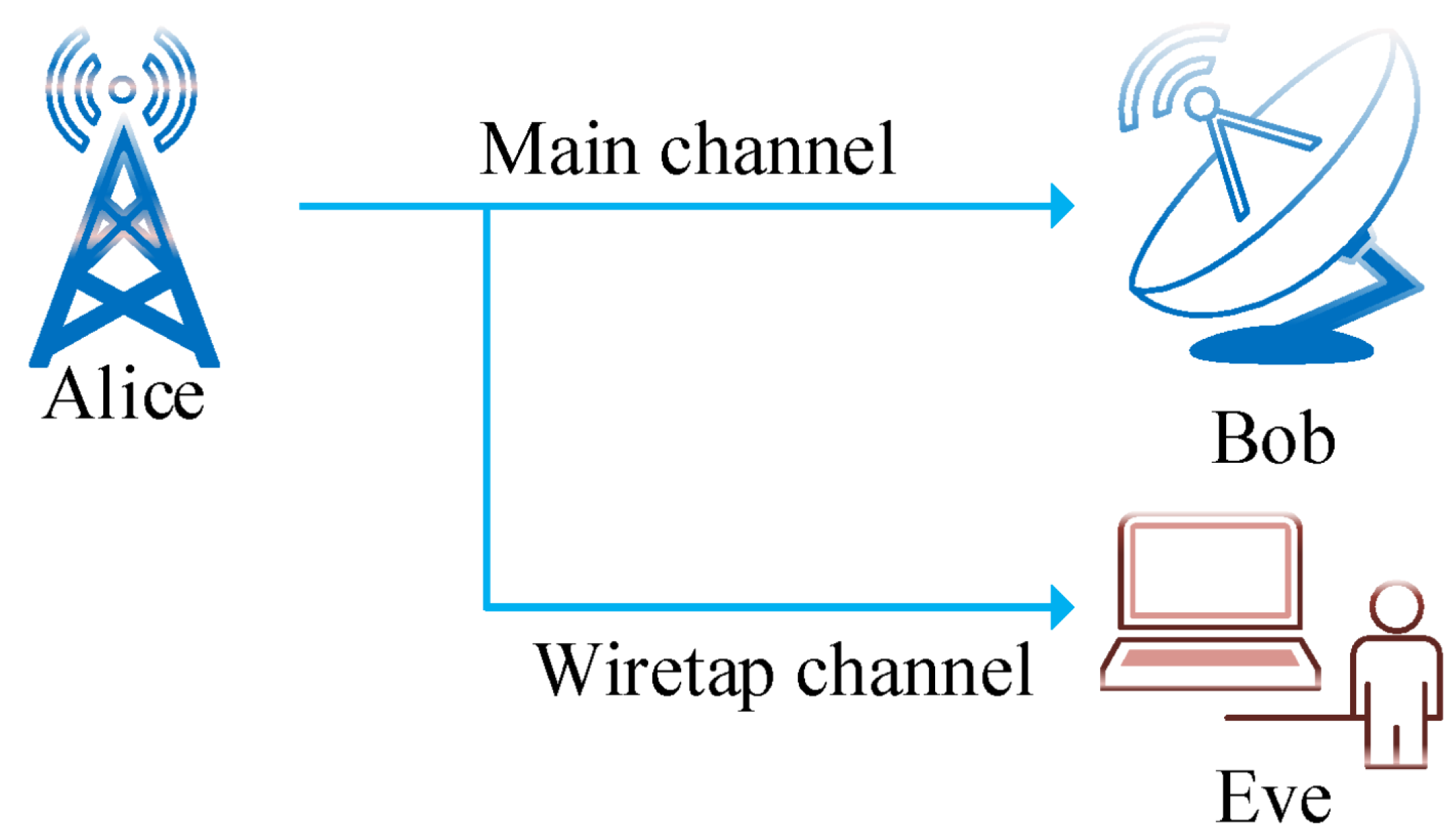
Figure 4.
Authentication Success Rate and Data Confidentiality Verification Rate evaluation with proposed methods [22].
Figure 4.
Authentication Success Rate and Data Confidentiality Verification Rate evaluation with proposed methods [22].
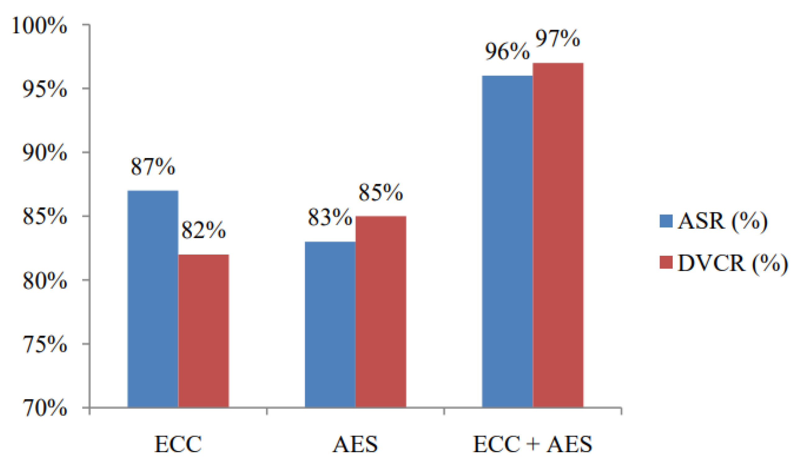
Figure 5.
Nanoantenna Model
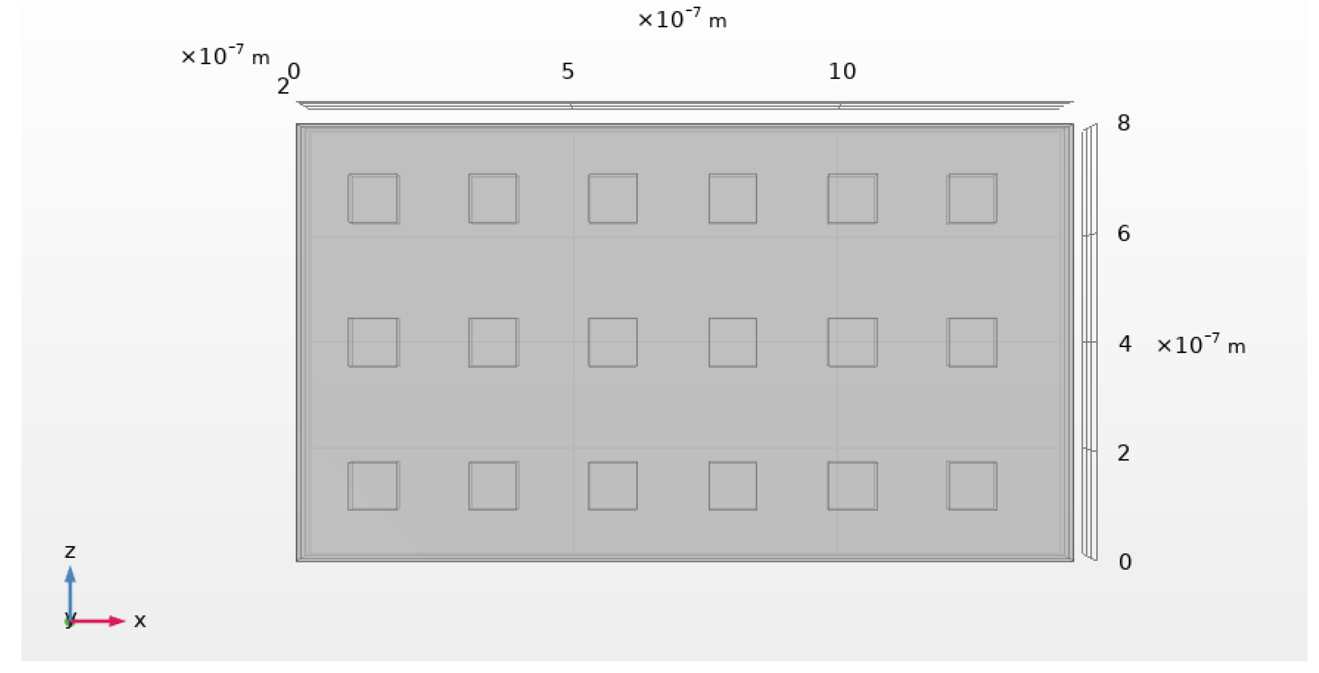
Figure 6.
Point of maximum electric field intensity.
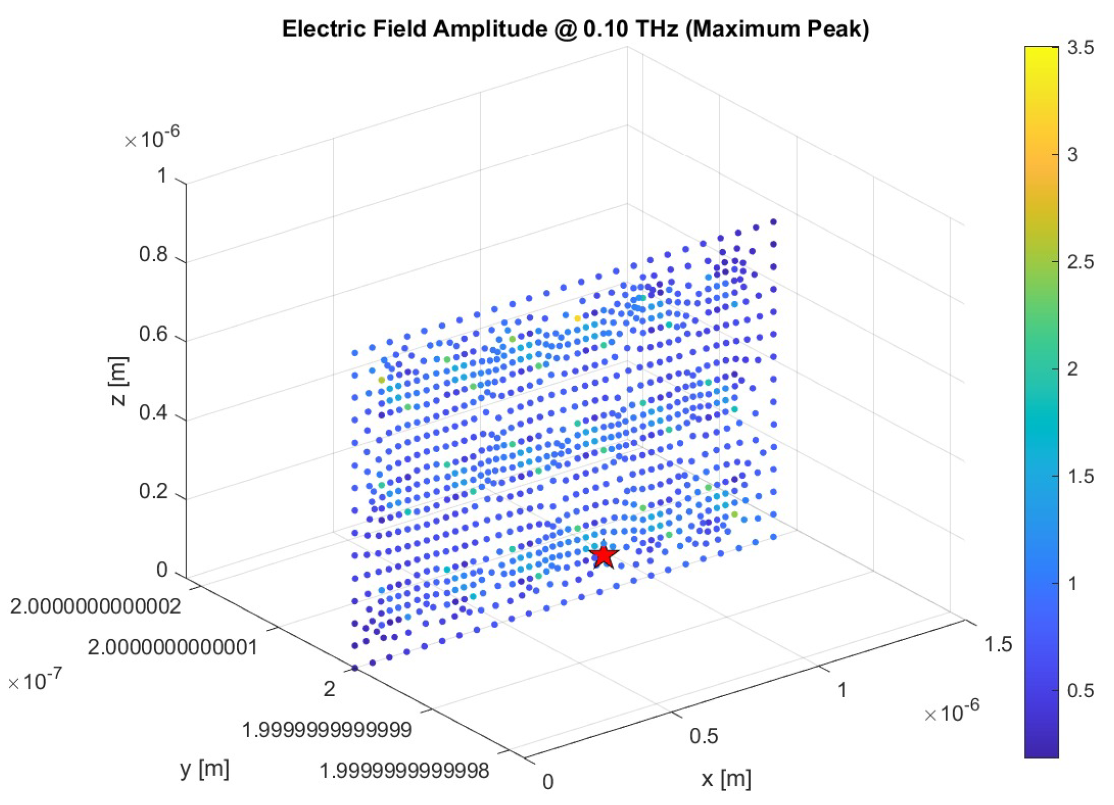
Figure 7.
Temporal Response of the Nanoantenna to a Gaussian Pulse
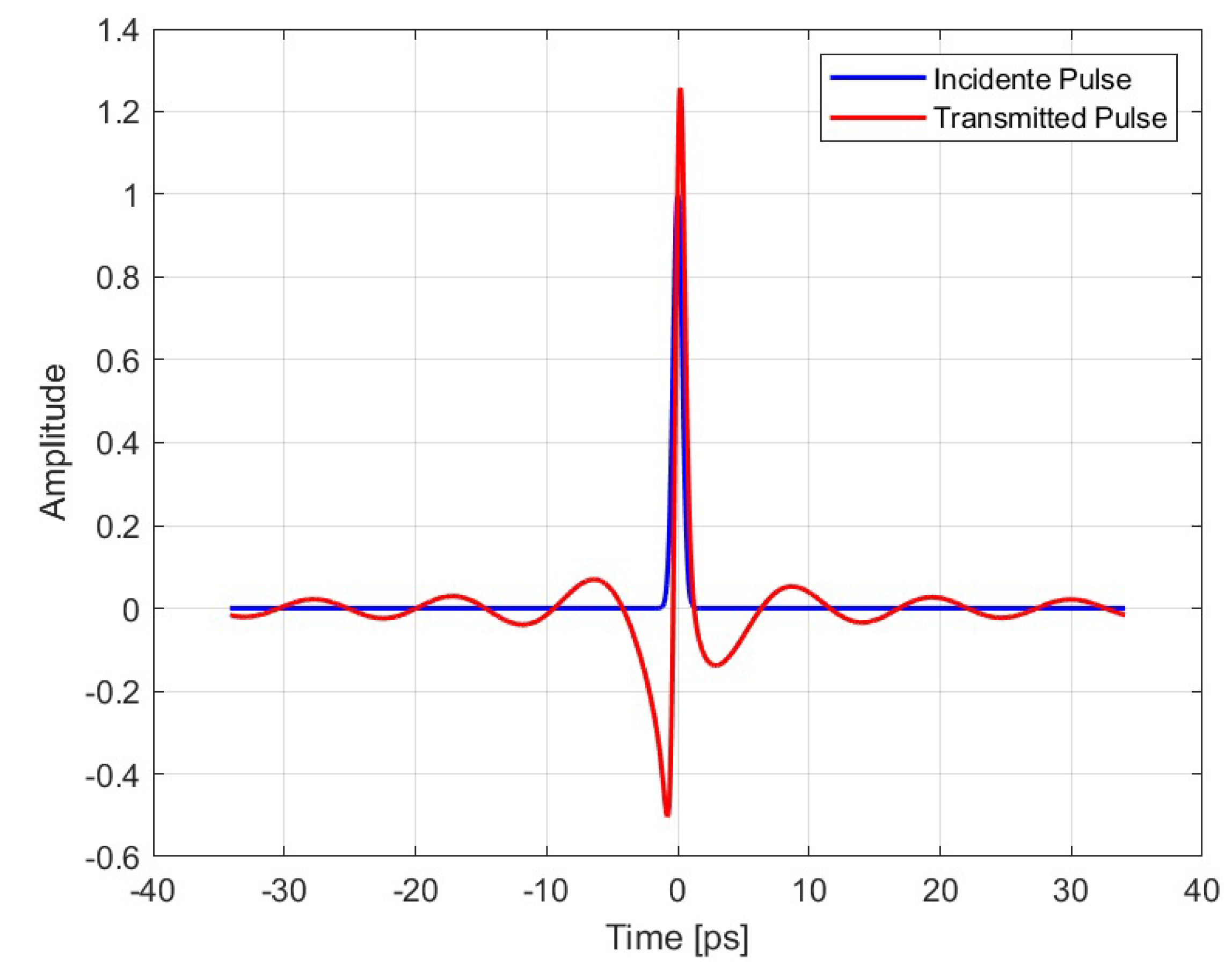
Figure 8.
Response to a Voice Signal
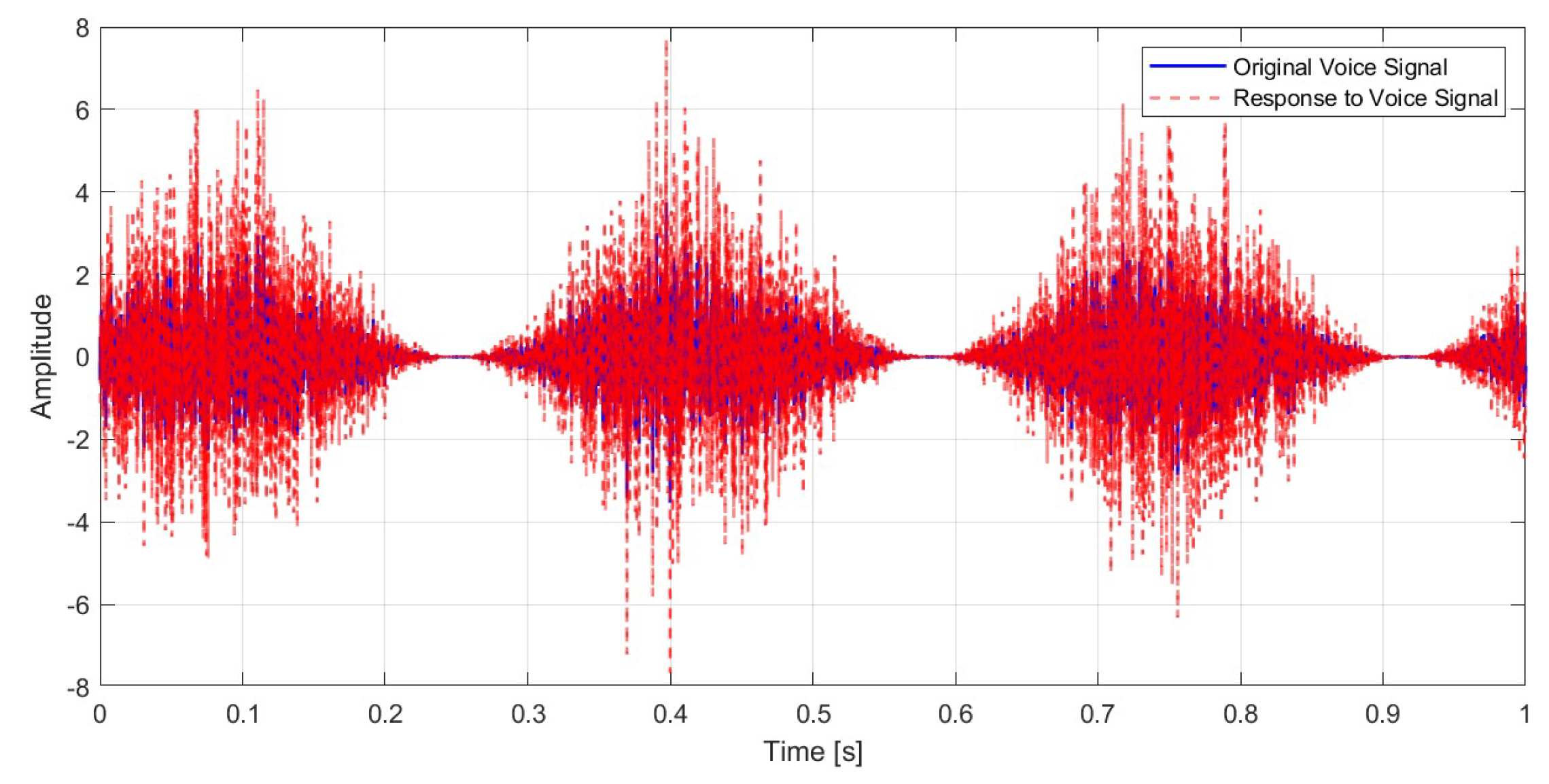
Figure 9.
Original vs Recovered Signal at ideal environment.
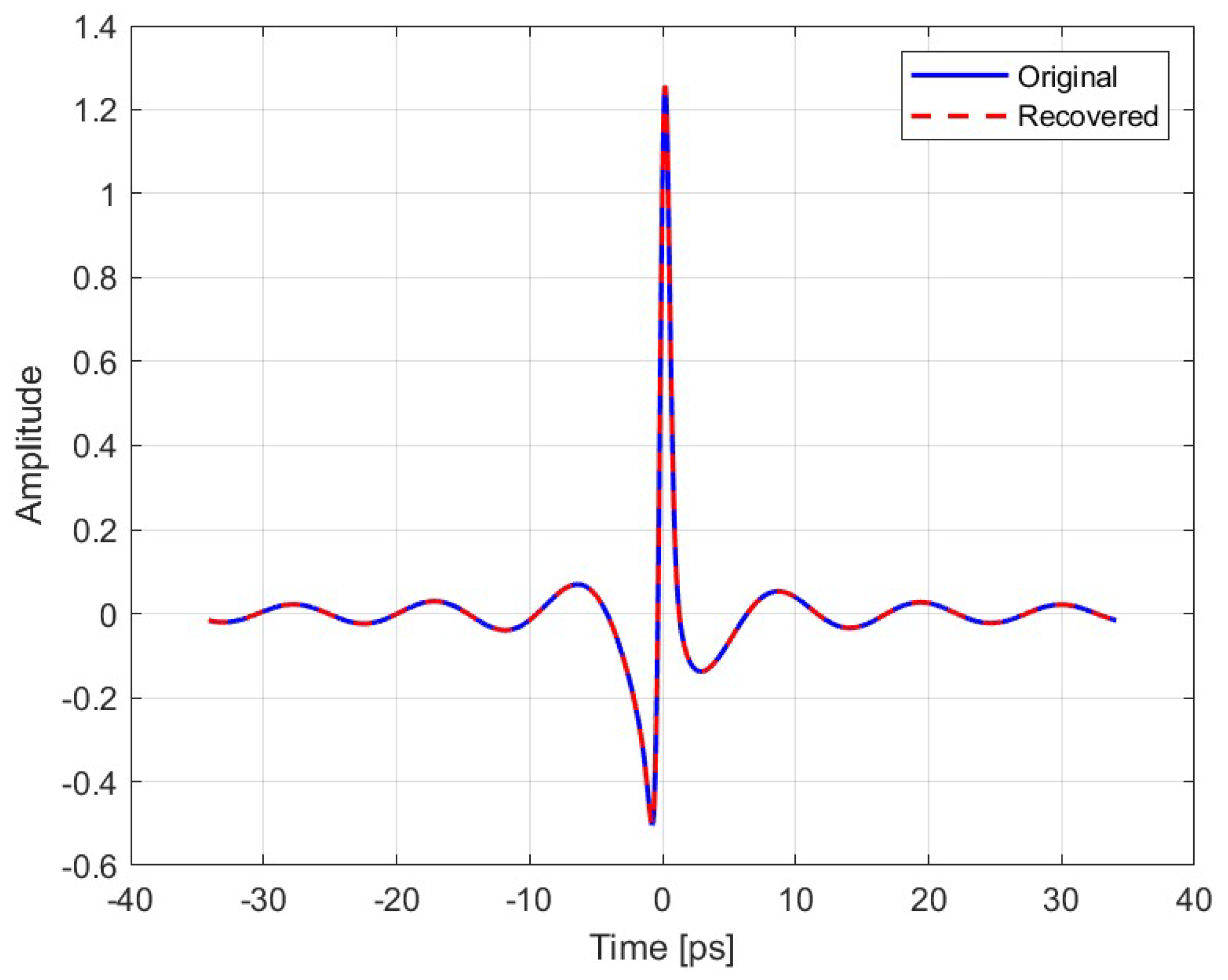
Figure 10.
Original vs Recovered Signal with Noise Power= 0.2 V/m.
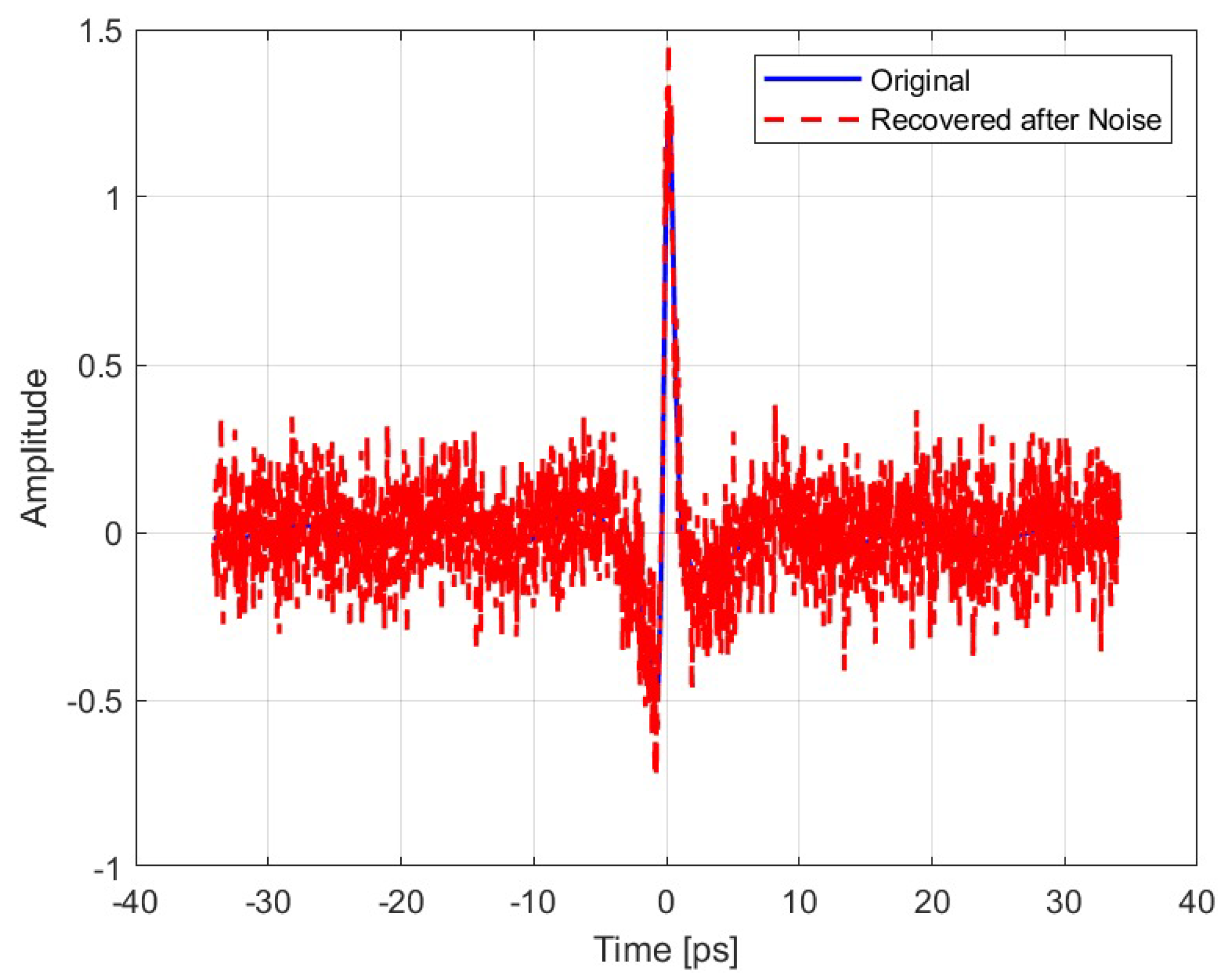
Figure 11.
Original vs Recovered Signal without key.
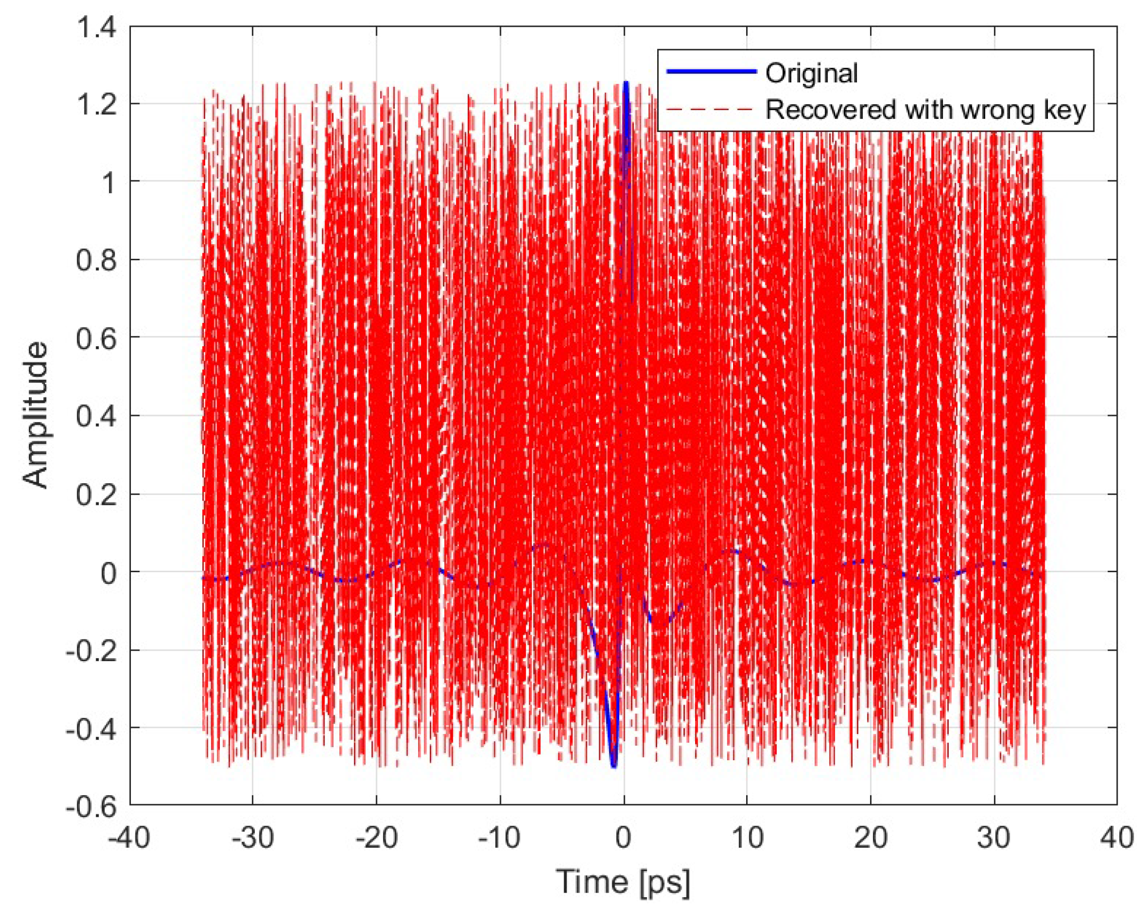
Figure 12.
AWGN Scenario.
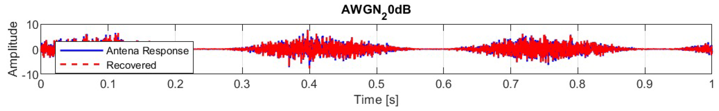
Figure 13.
Multipath Propagation Scenario
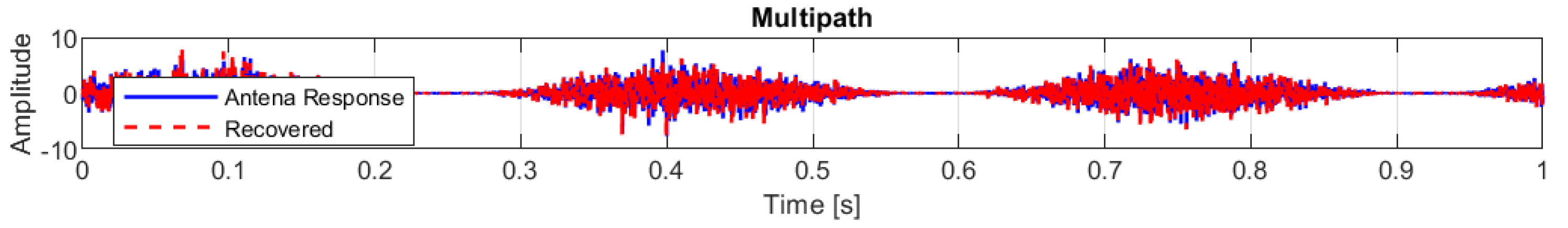
Figure 14.
Quantization Scenario
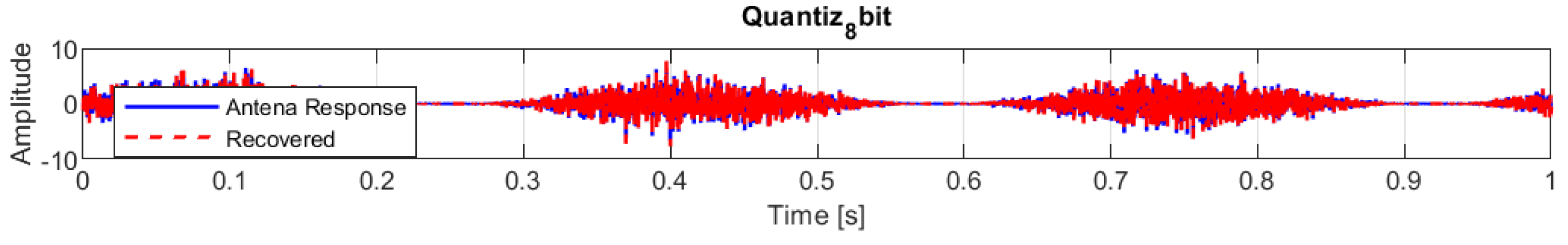
Figure 15.
Echo Scenario
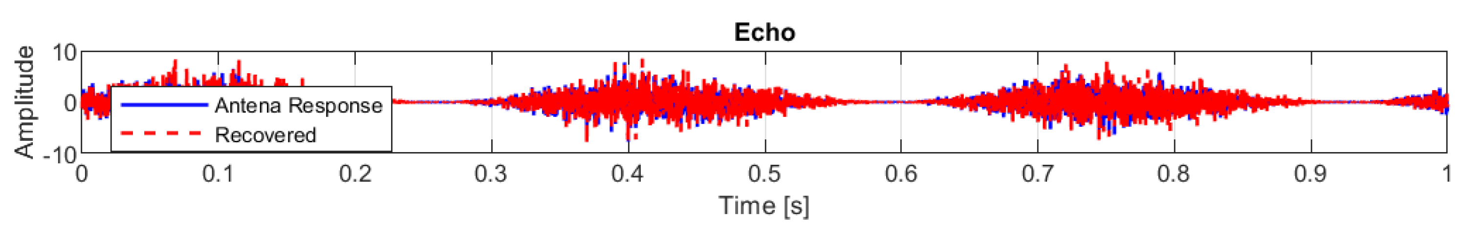

Table 1.
Geometric and material parameters used in the nanoantenna design.
| Name | Value | Unit | Description |
|---|---|---|---|
| E | m | Metal thickness | |
| m | Dielectric thickness | ||
| m | Design wavelength | ||
| L | m | Total length of the structure | |
| m | Side length of the apertures | ||
| m | Spacing between apertures | ||
| m | Aperture width | ||
| 3 | – | Number of apertures along x | |
| 6 | – | Number of apertures along z |
Table 2.
Results Summary.
| Scenario | Correlation | RMSE | PSNR (dB) | |
|---|---|---|---|---|
| Gaussian Signal | Ideal | 1.00 | 104.27 | |
| Noisy environment of 0.2 V/m | 0.7507 | 20.70 | ||
| Wrong key | 0.0118 | 5.78 | ||
| Voice Signal | AWGN | 0.99504 | 0.12914 | 35.527 |
| Multipath Propagation | 0.25789 | 1.6329 | 13.489 | |
| Quantization | 0.99991 | 0.017303 | 52.986 | |
| Echo | 0.85855 | 0.77097 | 20.008 |
Disclaimer/Publisher’s Note: The statements, opinions and data contained in all publications are solely those of the individual author(s) and contributor(s) and not of MDPI and/or the editor(s). MDPI and/or the editor(s) disclaim responsibility for any injury to people or property resulting from any ideas, methods, instructions or products referred to in the content. |
© 2025 by the authors. Licensee MDPI, Basel, Switzerland. This article is an open access article distributed under the terms and conditions of the Creative Commons Attribution (CC BY) license (http://creativecommons.org/licenses/by/4.0/).
Copyright: This open access article is published under a Creative Commons CC BY 4.0 license, which permit the free download, distribution, and reuse, provided that the author and preprint are cited in any reuse.


