Submitted:
10 July 2025
Posted:
10 July 2025
You are already at the latest version
Abstract
Anti-resonant hollow-core fibers have exhibited excellent performance in applications such as high-power pulse transmission, network communication, space exploration, and precise sensing. Employing anti-resonant hollow-core fibers instead of light guiding arms for transmitting laser energy at the 2.79 μm band can significantly enhance the flexibility of medical laser handles, reduce system complexity, and increase laser transmission efficiency. Nevertheless, common anti-resonant hollow-core fibers do not have the ability to maintain the polarization state of light during laser transmission, which greatly affects their practical applications. In this paper, we propose a polarization-maintaining anti-resonant hollow-core fiber applicable for transmission at the mid-infrared 2.79 μm band. This fiber features a symmetrical geometric structure and an asymmetric refractive index cladding, composed of quartz and a type of mid-infrared glass with a higher refractive index. Through optimizing the fiber structure at the wavelength scale, single-polarization transmission can be achieved at the 2.79 μm wavelength, with a polarization extinction ratio exceeding 1.01×10⁵, indicating its stable polarization-maintaining performance. Simultaneously, it possesses low-loss transmission characteristics, with the loss of the x-polarized fundamental mode being less than 9.8×10⁻³ dB/m at the 2.79 µm wavelength. This polarization-maintaining anti-resonant hollow-core fiber provides a more reliable option for the light guiding system of the 2.79 μm Er, Cr: YSGG laser therapy device.
Keywords:
mid-infrared laser
; optical fibers
; polarization-maintaining
1. Introduction
The Er, Cr: YSGG laser at the 2.79 μm mid-infrared band precisely lies within the strong absorption peak regions of water molecules and hydroxyapatite. Owing to the specificity of its wavelength, it holds significant application value and potential in biomedical applications [1,2]. In the application of mid-infrared lasers, it is requisite to convey and irradiate the laser to the treatment site of patients or biological targets through a flexible catheter. Most traditional mid-infrared laser medical apparatuses adopt light guiding arms for laser transmission. Constrained by the performance of mid-infrared wavelength diaphragms, the reflection of the light beam at large angles by several lenses at multiple joints results in considerable transmission losses. Coupled with the rigid structure, it is challenging to achieve flexible operation in any orientation within confined three-dimensional spaces such as the oral cavity [3,4], thereby presenting inconvenience in operation and use. Optical fibers thus emerge as the optimal alternative for replacing light guiding arms to address issues such as high losses and inflexibility. Currently, solid-core optical fibers, due to the severe absorption losses of quartz materials in the mid-infrared region, cannot be employed for mid-infrared laser transmission with wavelengths greater than 2.7 μm. For this reason, it is necessary to adopt glasses such as fluorides and chalcogenides with low absorption losses in the mid-infrared region for the fabrication of solid-core optical fibers. However, the physical and optical properties of these soft glass materials pose difficulties in the fabrication of optical fibers, such that their technical maturity and economic viability cannot compare with those of quartz optical fiber fabrication. More importantly, the damage threshold of these solid-core optical fiber materials, as well as the inevitable inherent nonlinearity, dispersion, and Rayleigh scattering of the materials themselves during the transmission of intense lasers, all restrict their application scope [5,6,7].
In recent years, the developed microstructure anti-resonant hollow-core fibers (AR-HCFs) form a negative curvature at the core boundary by constructing the cladding microstructure, strongly suppressing the overlap between the optical mode field and the glass material, thereby avoiding the interaction of light with the fiber material. The light beam is confined and transmitted in the core air, thus enabling low-loss transmission even when the AR-HCFs are made of high-loss materials [8,9,10,11,12]. Silica AR-HCFs possess advantages such as low nonlinearity, low latency, low dispersion, and high damage threshold. They have been successfully applied in biomedical imaging and sensing [13,14,15], and in a fiber with a core diameter of 24 µm, the transmission of 2.94 µm laser energy can reach 500 mJ, satisfying the requirements of clinical applications. However, during the laser transmission process in a common AR-HCF, the polarization characteristics of the light are influenced by external temperature, random birefringence, polarization mode dispersion, and polarization loss [16], and the polarization maintaining performance of AR-HCF has become a research focus. Currently, both domestic and international research on polarization-sensitive AR-HCFs mainly concentrates on 1.55 µm. In 2016, Ding et al. first proposed the method of introducing high birefringence by altering the wall thickness of the cladding tubes in the orthogonal direction of the AR-HCF [17]. In 2018, Wei et al. proposed a six-tube negative curvature hollow-core fiber, where the polarization extinction ratio (PER) reached 850 at 1.55 µm [18]. In 2018, Yan et al. proposed a single-polarization double-ring NCF where the PER could reach 17,000 at 1.55 µm. Although this NCF can operate under single-polarization single-mode guidance and has good bending performance, the single-polarization single-mode bandwidth only covers 8 nm [19]. In 2018, Yan et al. from Beijing Jiaotong University proposed a single-mode single-polarization anti-resonant hollow-core fiber with a PER of 17,662 at the working wavelength of 1,550 nm, and its fundamental mode minimum loss was 0.04 dB/m [20]. In 2020, Yerolatsitis et al. from the University of Bath fabricated a highly birefringent HC-NCF with a birefringence of 2.35×10⁻⁵ at a wavelength of 1550 nm and a transmission loss of 0.46 dB/m [21]. To the best of our knowledge, in the 2.79 µm mid-infrared band, which has significant applications in biomedicine, environmental detection, and nonlinear optics research, studies on AR-HCFs with polarization maintaining characteristics have not been reported yet.
In this paper, a polarization-maintaining anti-resonant hollow-core fiber with a symmetric geometric structure and an asymmetric refractive index cladding is designed. The nested tubes consist of fused silica and a mid-infrared glass with a higher refractive index. By varying the refractive index of the cladding in the X and Y directions, the polarization mode in the Y direction is coupled with the cladding mode, resulting in a larger polarization loss in the Y direction to achieve polarization characteristics. Through structural optimization, single-polarization transmission at a wavelength of 2.79 μm is realized, with a polarization extinction ratio reaching 2.1×10⁵, and its polarization-maintaining performance has excellent stability; simultaneously, it exhibits low-loss transmission characteristics, with the x-polarization fundamental mode loss at a wavelength of 2.79 µm being only 1.8×10⁻⁴ dB/m. Utilizing this structure of the polarization-maintaining anti-resonant hollow-core fiber to replace the light guide arm for the transmission of the 2.79 μm mid-infrared laser waveband solves the problems of high loss, low efficiency, and inflexibility of the light guide arm.
2. Design Polarization-Maintaining AR-HCF for Transmission at 2.79 μm Wavelength
In this paper, a polarization-maintaining anti-resonant hollow-core fiber (AR-HCF) composed of 4 cladding tubes and 4 nested tubes is designed. The numerical calculation and analysis of the polarization-maintaining AR-HCF are conducted using the finite element method, and the structure is shown in Figure 1. The core diameter is D, the outer diameter of the cladding tube is d2, and the maximum distance between the inner diameter of the nested tube and the cladding tube is Z = d2 - d1 - t. The finite element method is employed for modeling, and the confinement loss can be solved by Equation (1) [22]:
Where λ is the incident wavelength and neff is the effective refractive index. neff can be solved by Equation (2) [23]:
As depicted in Figure 1, the yellow portion represents the high refractive index material, the white part indicates air, and the light blue section stands for quartz. The refractive index of quartz is denoted by n1, and that of the high refractive index material is represented by n2. The diameter of the air core is D, the wall thickness of the inner nested capillary is t, and the wall thickness of the outer capillary is T. Subsequently, we fix the core diameter at 85.68 μm. According to the resonance principle of the AR-HCF, the wall thicknesses of the inner and outer capillaries are the same at 0.72 μm. The wall thickness of the inner nested capillary d1 = 80 μm and the wall thickness of the outer capillary d2 = 91 μm remain unchanged. Firstly, we analyze the single-polarization performance at different n2 values to obtain n2 that can suppress the y-polarized fundamental mode, that is, to investigate the influence of the refractive index of the different high refractive index material parts on the polarization-maintaining AR-HCF we designed. The results are presented in Figure 2.
The polarization extinction ratio (PER) is defined as Equation (3) [24], and when the PER value is greater than 100, it can be considered that the fiber will maintain a single-polarization transmission state:
Wherein, and represent the confinement losses of the fundamental modes of X and Y polarization states, respectively.
As depicted in the lower graph of Figure 2, the modal field distribution maps of the x-polarized fundamental mode and the y-polarized fundamental mode are presented when n2 = 2.5. It can be observed from the figure that the x-polarized fundamental mode is well confined within the core area, while the y-polarized fundamental mode couples with a mode attached to the high refractive index cladding. Consequently, the loss of the y-polarized fundamental mode is extremely high, thereby enabling single-polarization transmission. At this moment, the PER is 887. Through the analysis, single-polarization transmission has been successfully achieved with the design of an asymmetric refractive index distribution cladding structure at the target wavelength of 2.79 μm.
3. Results and Discussion
3.1. The Influence of the Inner Diameter of the Embedded Casing Pipe on PER
After conducting research on the refractive index of the cladding tube in the y-direction, it was obtained that the y-direction polarization mode couples with the surface mode of the cladding tube in the y-direction. Subsequently, through the investigation of the inner diameter d1 of the inner embedded cladding capillary and n2, in order to enhance the coupling between the y-direction polarization mode and the surface mode of the cladding tube and thereby obtain a greater PER, we fixed the core diameter at 85.68 μm. According to the resonance principle of the AR-HCF, the wall thicknesses of the inner and outer capillaries were made the same at 0.72 μm. The wall thickness d1 of the inner embedded capillary was selected within the range of 60 - 85 μm, the wall thickness d2 of the outer capillary was maintained at 91 μm, and the refractive index n2 of the higher refractive index material was chosen within the range of 2.0 - 2.5. The influence of the inner diameter of the embedded tube on PER was studied. In other words, what we investigated was the impact of the distance between the inner embedded tube and the outer cladding tube on the calculation results. Because the introduction of the nested anti-resonance tube increased the radial air-glass anti-resonance layer, the inner embedded tube could reduce the weak interference overlap between the core and cladding modes, thereby reducing the confinement loss and bending loss of the core. However, what we expected was an increase in the y-direction leakage loss and a decrease in the x-direction leakage loss. A suitable inner diameter of the embedded tube was required to achieve this effect. The calculation results are presented in Figure 3.
From Figure 3, it can be observed that when n2 = 2.5 and d1 = 78 μm, the confinement loss of the y-direction polarization mode is significantly greater than that of the x-direction polarization mode. At this point, the core mode in the y-direction strongly couples with the cladding tube mode, and the vast majority of the y-direction polarization mode leaks into the cladding tube. The maximum PER at this moment is 841.1. When n2 = 2.5 and d1 = 68 μm, which is in the yellow area in the middle of the figure, the y-direction polarization mode weakly couples with the surface mode of the cladding tube, and only a small portion of the mode leaks into the cladding, resulting in a PER of less than 100 for both the x and y-direction polarization modes. Overall, it is not feasible to infinitely increase the distance between the inner embedded tube and the outer cladding tube merely to enhance the leakage loss in the y-direction. A relatively appropriate distance is of paramount importance. Eventually, through calculations, it is determined that the most suitable distance between the two, Z = 13.097 μm. On the right side are the mode field diagrams of the two eigenmodes. The x-direction polarization mode, due to the thickness of the cladding tube, has a suppressing effect on coupling, concentrating the optical energy in the core and preventing mode coupling. The y-direction polarization mode couples with the surface mode of the cladding tube, leading to the leakage of part of the mode field energy to the surface of the cladding tube.
3.2. The Inner Diameter of the Jacketed Pipe Affects the PER
The core diameter D of the optical fiber is fixed at 85.68 μm, the thicknesses of the inner and outer cladding tubes are the same at 0.72 μm, the refractive index of the y-direction cladding tube material is set at 2.5, and the distance Z from the embedded tube to the outer cladding tube remains unchanged at 13.097 μm as described in Section 3.1. Next, the influence of the outer cladding tube d2 on the polarization-maintaining AR-HCF is investigated. Since changes in the capillary radius can induce variations in the capillary gap and have an impact on the confinement loss characteristics of all polarization modes, including the fundamental mode and higher-order modes, in the core area, the optimization of the capillary radius is of great significance for the design of single-polarization hollow-core fibers. The calculation results are shown in Figure 4.
From Figure 4, it can be observed that when d2/D = 1.072 (within the yellow shaded region), the loss of the y-polarization fundamental mode exceeds 2000 dB/m, while the loss of the x-polarization fundamental mode is 0.117 dB/m. A portion of the x-polarization fundamental mode undergoes micro-coupling with the cladding mode, resulting in a relatively large leakage loss of the x-polarization fundamental mode. At this point, the polarization extinction ratio is greater than 17524. Although the PER value is favorable at this moment, the low-loss transmission of the x-polarization fundamental mode still needs to be considered. When d2/D = 1.062 (within the red shaded region), the loss of the y-polarization fundamental mode is 11.264 dB/m, but the loss of the x-polarization fundamental mode is merely 0.00987 dB/m. Under these conditions, only the x-polarization fundamental mode can be stably transmitted within the fiber core, and the polarization extinction ratio is 1141.52, indicating the realization of single-mode transmission of the x-polarization fundamental mode of the fiber. The loss of the y-polarization fundamental mode undergoes significant fluctuations with the alteration of d2 and maintains a relatively high loss value. Hence, in this section, the optimal parameter for the capillary radius d2/D is selected as 1.062.
3.3. The Core Diameter Affects the PER
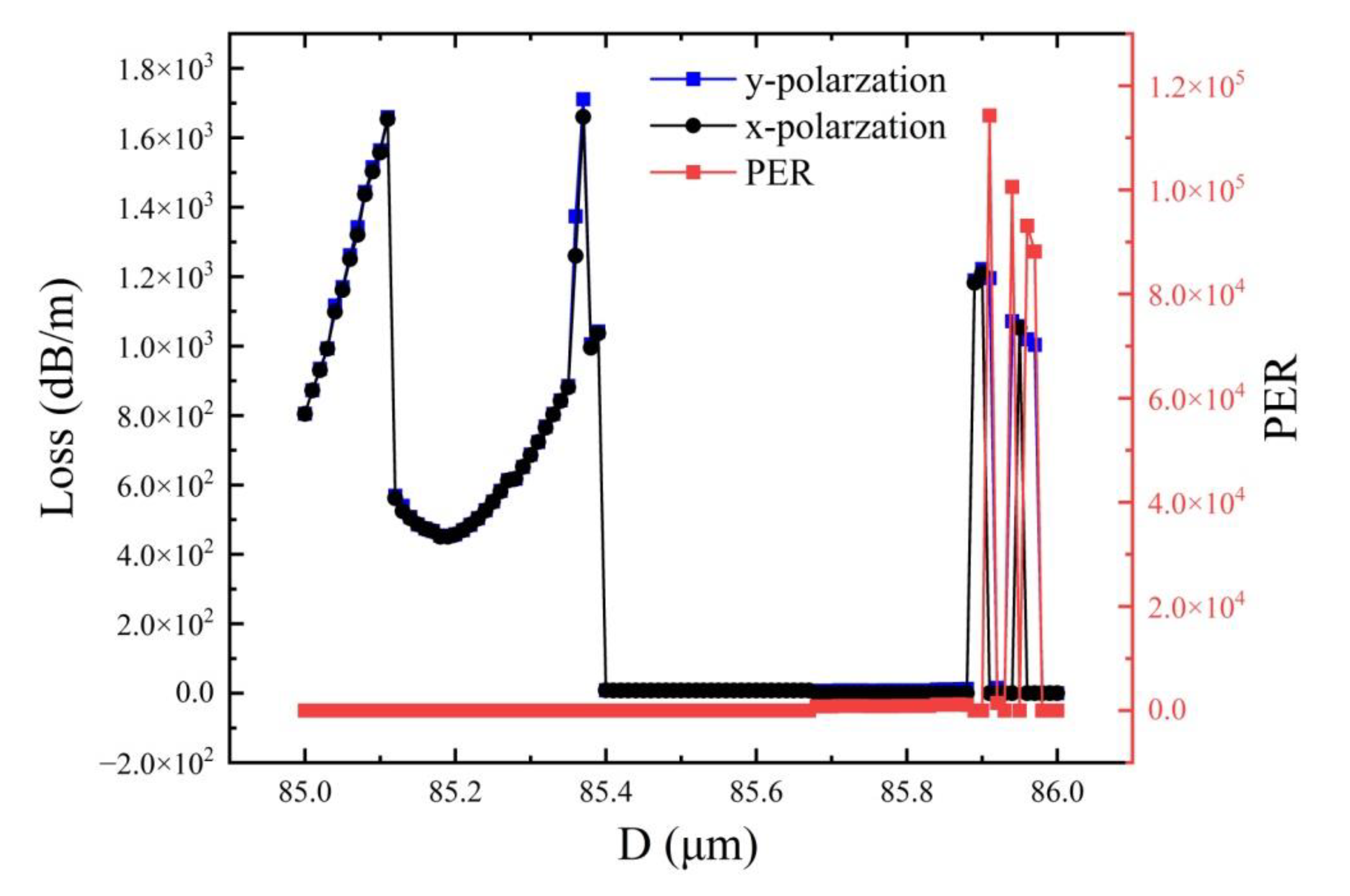
By varying the core diameter, the effective mode area of the optical fiber can be modified, and the losses of the fundamental mode and higher-order modes in the core can be regulated. Based on the optimizations in the previous two sections, a further analysis is carried out on the impact of the core diameter on the fiber’s performance. The initial structural parameters of the optical fiber are set as follows: the core diameter D is fixed at 85 μm, the thicknesses of the inner and outer cladding tubes are both 0.72 μm, the refractive index of the y-direction cladding tube material is set at 2.5, as described in Section 3.1, the distance Z from the embedded tube to the outer cladding tube remains constant at 13.097 μm, and the ratio d2/D of the outer cladding tube is 1.062. The results are presented in Figure 5.
Figure 5 depicts the variation relationship between the x-polarized fundamental mode loss, PER, and the core diameter D at a wavelength of 2.79 µm. It can be conspicuously observed that when the core diameter is 85.71 µm, the loss of the x-polarized fundamental mode is minimized, with a loss of 0.00932 dB/m and a PER value of 872. When the core diameter is 85.94 µm, the x-polarized loss is 0.01065 dB/m, and the PER is greater than 1.01×10⁵ at this point. Since the actual application scenario, we ultimately have only required transmission over a few meters, the loss of 0.01065 dB/m over short distances is adequate to meet the usage requirements. Therefore, we ultimately select D = 85.94 µm as the optimized structural parameter.
4. Conclusions
In recent years, high-refractive-index glasses have been continuously developed and fabricated, finding applications in optical instruments and equipment and significantly improving and enhancing optical performance. This paper proposes a polarization-maintaining AR-HCF featuring a layer of nested tubes and cladding tubes with different refractive indices in the x and y directions. Based on the finite element method, the influence of key structural parameters of the optical fiber, such as the refractive index of the high-refractive-index material, the core diameter, the outer diameter of the cladding tube, and the inner diameter of the nested cladding tube, on the transmission characteristics of the polarization-maintaining AR-HCF is analyzed. The theoretical concept of this paper focuses on guiding the surface mode of the y-direction cladding tube to anti-cross with the y-direction polarization mode by adjusting the refractive index of the y-direction cladding tube, achieving phase matching of the two modes, and increasing the leakage of the y-direction fundamental mode, thereby obtaining the polarization-maintaining AR-HCF. The numerical results indicate that the designed optical fiber in this paper can achieve a confinement loss of the x-direction polarization mode of 1.065×10⁻² dB/m at 2.79 μm, with a PER greater than 1.01×10⁵. The polarization-maintaining AR-HCF structure designed herein is simple and straightforward for fabrication, with a relatively large core diameter, facilitating the coupling of a mid-infrared 2.79 μm laser with a large spot diameter and featuring low transmission loss. The use of this structure for the transmission of the mid-infrared 2.79 μm Er, Cr: YSGG laser in polarization-maintaining AR-HCF enables convenient multi-directional and multi-angle operation by surgeons in clinical applications. This study provides valuable reference and theoretical guidance for the development of optical transmission technology and clinical application research of mid-infrared laser medical instruments.
References
- Huang, L.; Wang, Y.; Zhang, Y.; et al. High-efficiency 6-hole structure anti-resonant hollow-core fiber 2.79 μm Cr, Er: YSGG high-energy pulse laser transmission system. Optics and Laser Technology 2024, 175, 110743. [Google Scholar] [CrossRef]
- Urich, A.; Maier, R.; Yu, F.; et al. Flexible delivery of Er: YAG radiation at 2.94 µm with negative curvature silica glass fibers: a new solution for minimally invasive surgical procedures. Biomedical Optics Express 2013, 4, 193–205. [Google Scholar] [CrossRef]
- Huang, L.; Wang, P.; Wang, Y.; et al. Mid-Infrared 2.79 μm Band Er, Cr: Y3Sc2Ga3O12 Laser Transmission Anti-Bending Low-Loss Anti-Resonant Hollow-Core Fiber. Photonics 2024, 11, 432. [Google Scholar] [CrossRef]
- Sincore, A.; Cook, J.; Tan, F.; El Halawany, A.; et al. High power single-mode delivery of mid-infrared sources through chalcogenide fiber. Optics Express 2018, 26, 7313–7323. [Google Scholar] [CrossRef]
- Wang, C.; Zhang, Z.; Tang, Y.; Jin, W.; et al. Hollow optical fiber based spectroscopy gas sensing. Optical Fiber Technology 2024, 88, 103824. [Google Scholar] [CrossRef]
- Yu, F.; Knight, J.C. Negative curvature hollow core optical fiber. IEEE Journal of Selected Topics in Quantum Electrons 2016, 22, 4400610. [Google Scholar] [CrossRef]
- Wei, C.; Weiblen, R.J.; Menyuk, C.R.; Hu, J. Negative curvature fibers. Advances in Optics and Photonics 2017, 9, 504–561. [Google Scholar] [CrossRef]
- Gong, Y.; Meng, Y. Single-polarization single-mode broadband ultra-low loss hollow-core anti-resonant fiber with nested double C-type cladding tubes. Optics Communications 2024, 552, 130062. [Google Scholar] [CrossRef]
- Gao, S.; Wang, Y.; Ding, W.; Wang, P. Hollow-core negative-curvature fiber for UV guidance. Optics Letters 2018, 43, 1347–1350. [Google Scholar] [CrossRef]
- Jaworski, P.; Krzempek, K.; Bojęś, P.; et al. Mid-IR anti-resonant hollow-core fiber based chirped laser dispersion spectroscopy of ethane with parts per trillion sensitivity. Optics and Laser Technology 2022, 156, 108539. [Google Scholar] [CrossRef]
- Popendaetal, M.A. Application of negative curvature hollow-core fiber in an optical fiber sensor setup for multiphoton spectroscopy. Sensors 2017, 17, 2278. [Google Scholar] [CrossRef] [PubMed]
- Litchinitser, N.; Abeeluck, A.; Headley, C. Anti resonant reflecting photonic crystal optical waveguides. Optics Letters 2002, 27, 1592–1594. [Google Scholar] [CrossRef]
- Wang, S.; Shan, C.; Jiang, J.; et al. Temperature-insensitive curvature sensor based on anti-resonant reflection guidance and Mach–Zehnder interferometer hybrid mechanism. Applied Physics Express 2019, 12, 106503. [Google Scholar] [CrossRef]
- Mousavi, S.; Sandoghchi, S.; Richardson, D.; Poletti, F. Broad-bandhigh birefringence and polarizing hollow core anti-resonant fibers. Optics Express 2016, 24, 22943–22958. [Google Scholar] [CrossRef]
- Jaworski, P.; Yu, F.; Maier, R.; Wadsworth, W.; et al. Picosecond and nanosecond pulse delivery through a hollow-core Negative Curvature Fiber for micro-machining applications. Optics Express 2013, 21, 22742–22753. [Google Scholar] [CrossRef]
- Daniel, A.; Nolan, E.; George, E.; et al. Single-polarization fiber with a high extinction ratio. Optics Letters 2004, 29, 1855–1857. [Google Scholar]
- Din, W.; Wang, Y. Hybrid transmission bands and large birefringence in hollow-core anti-resonant fibers. Optics Express 2015, 23, 21165. [Google Scholar]
- Wei, C.; Menyuk, C.R.; Hu, J. Polarization-filtering and polarization-maintaining low-loss negative curvature fibers. Optics Express 2018, 26, 9528–9540. [Google Scholar] [CrossRef]
- Yuan, Z.; Wang, Y.; Yan, D.; Cao, M.; Meng, M.; Li, X.; Sun, S. Study on the high birefringence and low confinement loss terahertz fiber based on the combination of double negative curvature and nested claddings. Journal of Physics D Applied Physics 2022, 55, 115106. [Google Scholar] [CrossRef]
- Yan, S.; Lou, Q.; Zhang, W.; et al. Single-polarization single-mode double-ring hollow-core ant-resonant fiber. Optics Express 2018, 26, 31160–31171. [Google Scholar] [CrossRef]
- Yang, S.; Sheng, X.; Zhao, G.; Li, S. Simple birefringent Terahertz fiber based on elliptical hollow core. Optical Fiber Technology 2019, 53, 102064. [Google Scholar] [CrossRef]
- Saitoh, K.; Koshiba, M. Single-polarization single-mode photonic crystalfibers. IEEE Photonics Technology Letters 2003, 15, 1384–1386. [Google Scholar] [CrossRef]
- Nazeri, K.; Bradley, C. The effect of photonic crystal fibre structure on the performance of Mach-Zehnder interferometer fibre optic gas sensors. Optical Fiber Technology 2020, 58, 102294. [Google Scholar] [CrossRef]
- Mousavi, S.; San, R.; David, J.; et al. Broad band high birefringence and polarizing hollow-core anti-resonant fibers. Optics Express 2016, 24, 22943. [Google Scholar] [CrossRef]
Figure 1.
End face Diagram of Polarization-Maintaining AR-HCF.

Figure 2.
The variations of x-polarized loss and PER with n2 when the incident wavelength is 2.79 µm and the field distributions of X and Y polarized fundamental modes at n2 = 2.5.
Figure 2.
The variations of x-polarized loss and PER with n2 when the incident wavelength is 2.79 µm and the field distributions of X and Y polarized fundamental modes at n2 = 2.5.
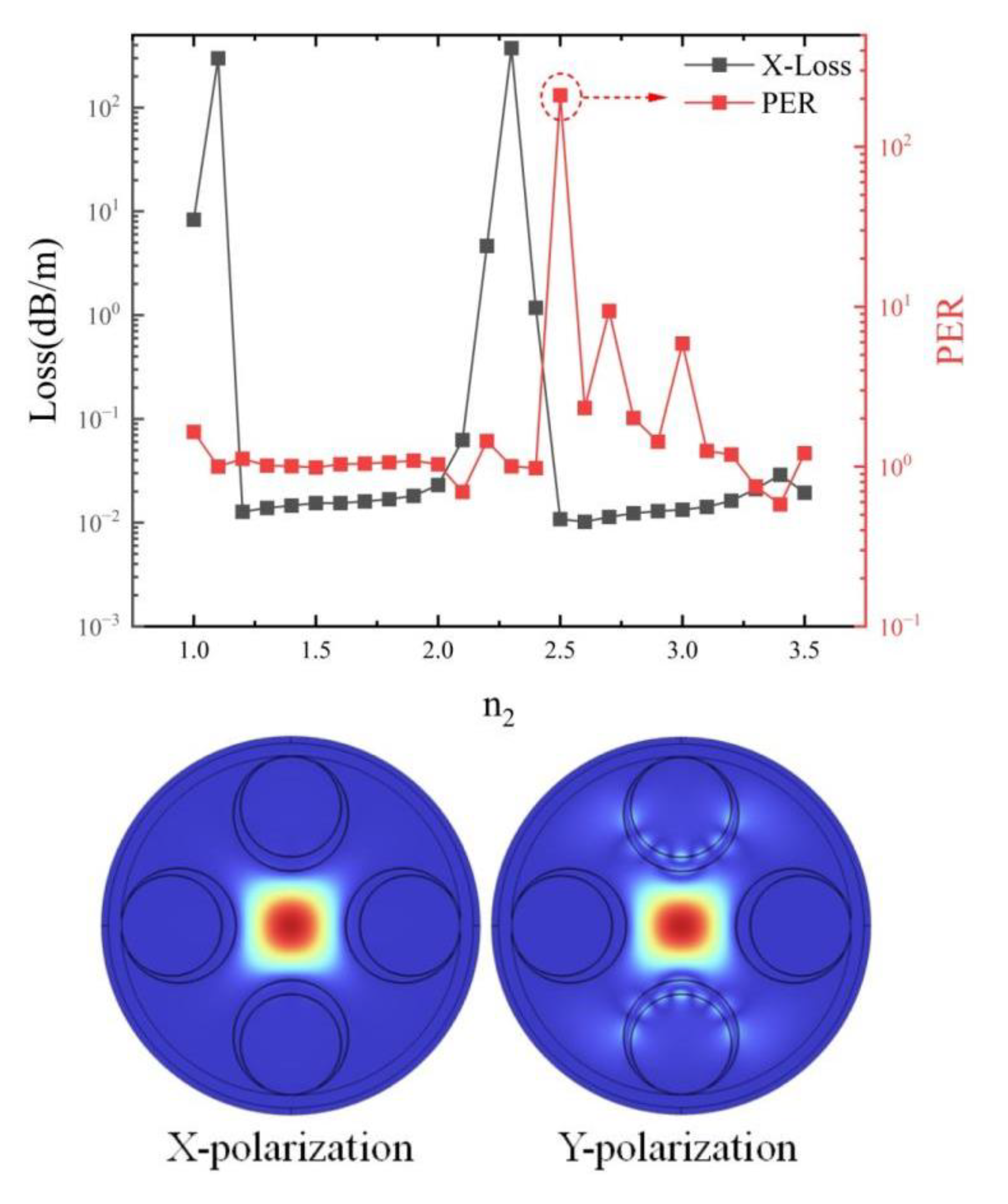
Figure 3.
The impact of the inner diameter d1 and the refractive index n2 of the nested cladding tube on the polarization-maintaining characteristics of the optical fiber, and the distribution maps of the x and y polarization modes at d1 = 78 μm and n2 = 2.5.
Figure 3.
The impact of the inner diameter d1 and the refractive index n2 of the nested cladding tube on the polarization-maintaining characteristics of the optical fiber, and the distribution maps of the x and y polarization modes at d1 = 78 μm and n2 = 2.5.
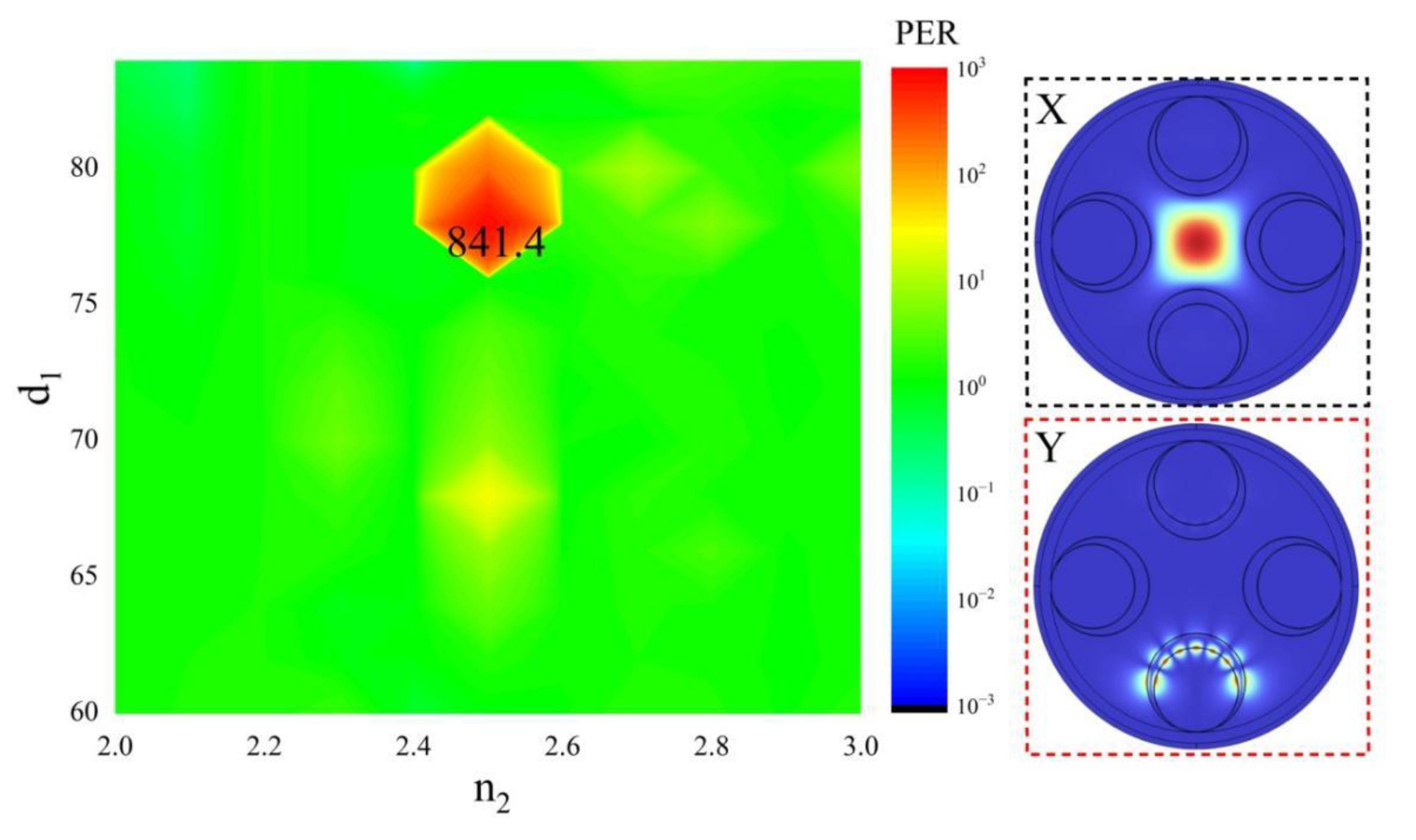
Figure 4.
The effect of the inner diameter of the cladding tube on PER, and the curve chart of the loss limitation in the x direction as the cladding tube changes.
Figure 4.
The effect of the inner diameter of the cladding tube on PER, and the curve chart of the loss limitation in the x direction as the cladding tube changes.
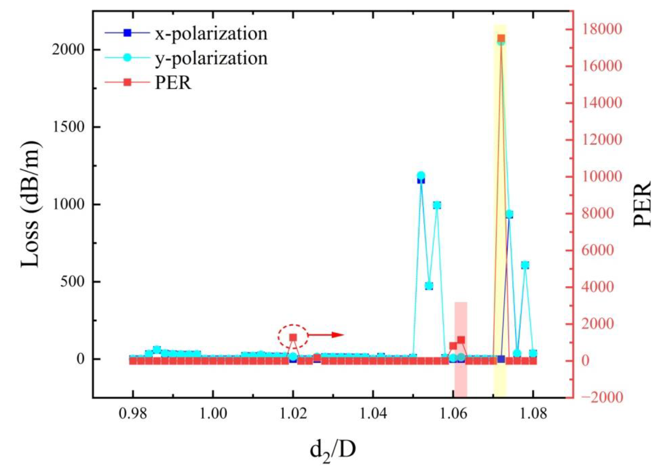
Figure 5.
Relationship between x and y polarization loss and PER with fiber core diameter.
Disclaimer/Publisher’s Note: The statements, opinions and data contained in all publications are solely those of the individual author(s) and contributor(s) and not of MDPI and/or the editor(s). MDPI and/or the editor(s) disclaim responsibility for any injury to people or property resulting from any ideas, methods, instructions or products referred to in the content. |
© 2025 by the authors. Licensee MDPI, Basel, Switzerland. This article is an open access article distributed under the terms and conditions of the Creative Commons Attribution (CC BY) license (http://creativecommons.org/licenses/by/4.0/).
Copyright: This open access article is published under a Creative Commons CC BY 4.0 license, which permit the free download, distribution, and reuse, provided that the author and preprint are cited in any reuse.


