Submitted:
07 July 2025
Posted:
08 July 2025
You are already at the latest version
Abstract
In this paper, a low loss and high polarization-maintaining single-mode hollow-core anti-resonant fiber (PM-HC-ARF) is designed. The elliptical core in the PM-HC-ARF is formed by strategically enlarging selected cladding air holes along the y-axis. Additionally, the variations in the wall thickness in both the x and y directions generate the distinct surface modes. We have effectively enhanced the birefringence performance of the fiber structure design by introducing the combined effect of the two. Theoretical analysis results show that the proposed PM-HC-ARF achieves a transmission loss of 0.82 dB/km at wavelength 1450 nm, along with a birefringence of 1.38 × 10⁻⁴, it demonstrates CL levels an order of magnitude below state-of-the-art polarization-maintaining HC-ARFs. Moreover, within the S+C+L+U communication bands, it achieves a bandwidth exceeding 380 nm(1420-1800nm) while maintaining a birefringence of greater than1.45 × 10-4. Especially, this PM-HC-ARF demonstrates a maximum higher-order mode extinction ratio of over 32,070, the single-mode transmission characteristics are excellent. along with exceptional bending resistance characteristic. When the bending radius exceeds 3 cm, the impacts on the loss and birefringence are negligible, this also demonstrates that the fiber structure shows good robustness when subjected to harsh environment interference. The proposed PM-HC-ARF is believed to have important applications in the fiber optic gyroscopes, optical amplifiers, and hydrophones.
Keywords:
low CL
; high birefringence
; hollow-core anti-resonant fiber
1. Introduction
Polarization-maintaining (PM) fibers play a crucial role in many optical technology fields, such as fiber optic gyroscopes (FOGs) [1,2,3], fiber optic sensors [4,5], and fiber lasers [6,7,8]. Researchers have developed various types of solid-core PM fibers (PMFs) [9]. Currently, solid-core PMFs exhibit the birefringence of higher than 10-4 and transmission loss of lower than 0.36 dB/km, respectively [10]. However, the solid-core PMFs have some inherent limitations, such as high material absorption loss, low damage thresholds, and high nonlinearity [11,12].
Hollow-core fibers (HCFs) have offered the breakthrough solutions to the technical bottlenecks faced by traditional solid-core fibers. The light-guiding mechanisms of HCFs include the photonic bandgap guidance [13] and anti-resonant guidance [14]. Hollow-core photonic bandgap fibers (HC-PBGFs) [15,16]can introduce high birefringence by adjusting the quartz walls around the core, leading to anti-cross coupling between the core mode and surface mode. However, for the HC-PBGFs, narrow guidance bandwidth, poor mode purity, and high surface scattering losses limit their application potential [17,18,19]. In contrast, hollow-core anti-resonant fibers (HC-ARFs) have larger design flexibility, wider transmission bandwidth, and lower transmission loss [20]. Although the HC-ARFs achieve a certain degree of mode overlap between the core and cladding region, the coupling between the fundamental mode and the cladding region is crucial for the fiber performance. However, due to the characteristics of the air core, it does not exhibit the photo elastic effect, which means that we cannot introduce the birefringence within the core structure by using traditional methods [21]. Therefore, the HC-ARFs face the challenges in achieving high birefringence (>10-4). Most of works on the HC-ARFs focuses on the birefringence enhancement, which can be achieved by changing the core shape, constructing the wall thickness differences, and modifying the cladding tube materials.
As is known to all, given the established efficacy of elliptical core geometries in inducing high birefringence (Hi-Bi) within conventional solid-core fibers [22]. Drawing inspiration from this principle, a direct method to introduce an effective refractive index difference in HCFs is to modify the core shape, such as by increasing the ellipticity of the core. This modification leads to differences in the fundamental mode profiles in the x and y directions, thereby achieving high birefringence of HC-ARF [23]. In 2013, Vincetti et al. conducted the theoretical simulations to investigate the influence of the elliptical aspect ratio of the HC-ARF core on its birefringence characteristics [24]. The theoretical results revealed that as the elliptical aspect ratio of the core increases, the birefringence also increases. The optimized fiber design achieved a maximum birefringence value of 7×10⁻⁵. However, the elliptical core constructed by the arrangement of cladding glass tubes could not introduce higher birefringence. In 2022, Wei et al. [25] proposed a quasi-elliptical core HC-ARF. By introducing an asymmetric polarization mode field in the elliptical core, a birefringence of 1.33×10⁻⁴ and a transmission bandwidth of 460 nm were achieved at 1.55 μm. However, this structure supports few-mode transmission, and the proposed fiber structure, which features an elliptical cladding tube, presents significant challenges in fabrication. In 2023, Wang et al. [26] introduced a crescent-shaped core AR-HCF with excellent birefringence performance, achieving a bandwidth of 300 nm and a loss limit of less than 1 dB/km at a birefringence level of 10⁻⁴. Only the fundamental mode purity is relatively low, Although the performance is superior, the fabrication of the glass cladding wall of this structure cannot be effectively realized through conventional pressure control methods.
Additionally, using tubes of varying thicknesses in orthogonal directions has been proven to be an indirect yet effective method for achieving high birefringence, as demonstrated by numerous studies. In 2016, Mousavi et al. [27] proposed to achieve high birefringence by constructing resonant and anti-resonant tubes in orthogonal directions. Although this design achieved a high birefringence of 1.5×10⁻⁴ at 1.55 μm, the loss was as high as 43 dB/km, but the higher-order mode suppression ratio (HOMSR) was not discussed. Subsequently, in 2018, Wei et al. [28] introduced the nested rings into a six-hole anti-resonant structure. Although this design simplified the fiber structure, the loss at 1.55 μm was as high as 20 dB/km, and the birefringence was only at the 10⁻⁵ level. In 2020, Yerolatsitis et al. [29]achieved a maximum loss of <1000 dB/km at 1.55 μm and a phase birefringence of 2.5×10⁻⁵ by introducing differences in cladding tube thickness in a six-hole HC-ARF. In 2022, Ding et al. designed and fabricated a novel four-hole nested anti-resonant fiber with a semi-circular cladding tube structure [30]. By constructing a thickness difference in the glass walls in orthogonal directions of the HC-ARF, an asymmetry in mode profiles was introduced, resulting in high birefringence. The fiber achieved a transmission loss of only 4.8 dB/km at 1.52 μm, but the phase birefringence was only 1.8×10⁻⁵, with a bandwidth of 154 nm. But the mode purity value of this fundamental mode is not theoretically specified. In 2024, Wang et al. [31] proposed a crescent-shaped nested HC-ARF with four-fold rotational symmetry. By designing thickness differences in the walls in orthogonal directions and utilizing the anti-crossing effect between core modes and glass modes, high birefringence was achieved. The fiber achieved a birefringence of 3.62×10⁻⁵ and a loss of 8.5 dB/km at 1.06 μm. Similarly, the high-order mode transmission loss is not mentioned. However, the use of this semi-tube structure imposes extremely stringent requirements on precise pressure control technology, and the fabrication process is highly demanding. Because most of the reported designs have a certain level of complexity or low feasibility in drawing processes, Meanwhile, the current birefringent anti-resonant fiber (ARF) cannot simultaneously achieve a higher higher-order mode suppression ratio and low-loss polarization-dependent transmission, To solve these questions, there is an urgent need to design a kind of polarization-maintaining PM-HC-ARF) which has good optical transmission characteristics while ensuring the practicality and operability of the structure.
In this paper, a PM-HC-ARF with different wall thickness and six-cladding holes is proposed. Unlike the mentioned single-solution designs, This fiber takes into account the combined effects of geometric polarization maintenance and surface mode polarization maintenance by combining the characteristics of an elliptical core and different wall thickness. Theoretical calculations indicate that within the wavelength range of 1420 to 1800 nm, the phase birefringence is greater than 1×10⁻⁴, reaching a maximum of 1.45×10⁻⁴. In the S+C+L+U communication band (~380 nm), the transmission loss is less than 8.8 dB/km. The higher-order mode suppression ratio is greater than 241 within the considered wavelength band, The purity of the fundamental mode transmission is satisfactory. Moreover, the PM-HC-ARF also exhibits excellent resistance to bending. Even with a bending radius as small as 3 cm, the x-polarized (x-pol) light loss is only 0.0078 dB/m, and the y-polarized (y-pol) light loss is only 0.0052 dB/m.
2. Structure Design and Principle
In this work, the cross-section of the proposed PM-HC-ARF that supports two polarization modes of the fundamental mode LP01 is shown in Figure 1. From Figure 1, the cladding structure includes a double-layer nested configuration with six holes, which is used to minimize the confinement loss. In the x-direction and y-direction, two kinds of cladding tubes are utilized. Specifically, in the y-direction, two larger cladding tubes are used to couple one polarization state of the core mode into the cladding mode, thereby enhancing the birefringence through an asymmetric core profile, which facilitates large birefringence while reducing differential loss between the fundamental core modes of the two polarizations. To achieve larger birefringence, it is crucial to ensure that the coupling between the core mode and cladding modes of the two polarization states occurs. Therefore, the wall thicknesses of the cladding tubes are carefully calculated, ensuring that the wall thickness of the four cladding tubes in the x-direction approaches the anti-resonant condition, while the wall thickness of the two cladding tubes in the y-direction approaches the resonant condition. The designed PM-HC-ARF structure exhibits a left-right symmetrical configuration, demonstrating strong feasibility for manufacturing. Additionally, the PM-HC-ARF structure is characterized by the following dimensions: in the y-direction, the radius of the first cladding tube is denoted as R1, with a wall thickness of t1; the radius of the first nested cladding tube is R2, with a wall thickness of t2; the radius of the second nested cladding tube is R3, with a wall thickness of t3. In the x-direction, the radius of the first cladding tube is R4, with a wall thickness of t4; the radius of the second nested cladding tube is R5, with a wall thickness of t5; the radius of the internal region of the outermost sleeve is R0. The long and short axes of the elliptical core in the horizontal direction are designated as a0 and b0.The angle of deviation θ=25°.
All simulations were performed using the finite element method. In the simulation, the maximum mesh size in the silica glass region should not exceed λ/5.8, while for air region it should not exceed λ/4. Perfectly Matched Layer (PML) boundaries were applied to the outermost layer of the geometry. The effective refractive index of the silica material was calculated using the following Sellmeier equation [32].
 where λ represents for the wavelength of the incident light. According to the resonance principle of HC-ARF, the light loss in the m-th anti-resonant frequency band is minimized when the resonance equation is satisfied [33].
 where nsilica is the refractive index of the silica glass, nair is the refractive index of air, and m is the order of resonance. When the light wavelength meets the specific anti-resonant condition, the light field energy is effectively confined within the core region, significantly reducing the confinement loss. Phase birefringence refers to the effective refractive index difference between the fundamental modes of the x and y-pol lights. This birefringence can be calculated using the following formula.
 where the effective refractive indices for the fundamental modes in the x and y directions are represented by nx and ny, respectively. The propagation constants for the modes in the two perpendicular directions are denoted as βx and βy, respectively. For the HC-ARF, this confinement loss (CL) can be calculated using the following formula [34].

The higher-order mode extinction ratio (HOMER) plays a critical role in communication transmission. Typically, the single-mode characteristic is determined by the HOMER, which can be expressed as [35].
 where CLHOM represents the minimum confinement loss of the HOM, and CL(x, y) −pol denotes the confinement loss of the x-pol and y-pol fundamental modes, respectively. Generally, when the HOMER is greater than 100, good single-mode transmission characteristics can be achieved. The initial structure parameters of the PM-HC-ARF are set as follow, . According to Eq.(2), the value of t is chosen to achieve the first anti-resonance band at an incident wavelength of 1550 nm. In the following, we aim to optimize the structure parameters to achieve the good transmission performances at specific wavelengths.
3. Results
3.1. Effect of R1 on Performance
In this section, we investigate the impact of the geometric parameter R1 on the confinement loss (CL) and birefringence of the designed PM-HC-ARF to optimize its performance. Simulations are conducted using the parameters established in the previous section, with the incident wavelength fixed at 1550 nm. Figure 2a,b show the dependence of CL on R1 for the x-pol and y-pol fundamental modes (FMs) within the wavelength range of 1420 to 1750 nm. When R1 is varied from 13.6 to 15.6 µm, the CL for both x-pol and y-pol FMs fluctuates between 3.82×10⁻⁴ dB/m and 8.05×10⁻³ dB/m for R1<14.4 µm. However, as R1 increases, the CL for both x-pol and y-pol FMs increases, reaching a maximum value at R1 = 15.6 µm. This increase is attributed to the reduced distance between the inner and outer layers of the nested tubes, leading to additional resonances. The initial lower CL for the y-pol FM is due to the smaller distance between the core and cladding tube in the y-direction, resulting in weaker coupling. Figure 2c shows the variation of birefringence with wavelength for six different values of R1: 13.6 µm- 15.6 µm. When R1 increases from 13.6 to 15.0 µm, the birefringence fluctuates within the range of 0.2×10⁻⁵ to 10⁻⁴, failing to achieve the desired high birefringence. However, the further increase of R1 leads to a significant increase in birefringence above 10⁻⁴. This enhancement is attributed to the increased coupling between the core and cladding modes. Figure 2d shows the mode field distributions of x-pol and y-pol FMs at 1.55 µm wavelength for different R1 values. The increase of R1 enhances the core ellipticity, which breaks the symmetry of the core’s polarization mode field, transforming it from a C6v to a C2v structure. This structural modification leads to a significant increase in the effective refractive index difference between x-pol and y-pol modes.
At R1 = 15.6 μm, while the x-pol FM remains well confined, the y-pol FM shows partial cladding leakage due to enhanced coupling, corresponding to peak birefringence of 1.62×10⁻⁴ with x-pol and y-pol CL values of 3.56×10⁻³ dB/m and 1.52×10⁻³ dB/m respectively. Across the 1420-1750 nm range, R1 values exceeding 15.2 μm consistently yield birefringence >1.45×10⁻⁴ while maintaining CL <10⁻² dB/m. This demonstrates that our elliptical-core design with specialized cladding achieves superior performance compared to conventional circular-core ARFs, with birefringence exceeding 1.6×10⁻⁴ at higher core ellipticity. The enhancement stems from geometric tuning of core ellipticity that breaks polarization symmetry, selectively strengthening coupling for specific polarizations. These results establish R1 = 15.6 μm as the optimal parameter for high birefringence. This section may be divided by subheadings. It should provide a concise and precise description of the experimental results, their interpretation, as well as the experimental conclusions that can be drawn.
3.2. Effects of k1, k2, k3 and R4, on Performance
The effects of k1, k2, k3, and R4 on the CL and birefringence are shown in Figure 3a–d. In the following discussion, the regions with a yellow background in the figure indicate areas where the confinement loss is below 0.01 dB/m. From Figure 3a, as k1 increases, the CLs for both x-pol and y-pol fundamental modes gradually decrease, along with polarization loss fluctuating between 7.34×10⁻² dB/m and 4.36×10⁻³ dB/m. Meanwhile, the birefringence generally exhibits a downward trend, and it fluctuates within the range of 1.09×10⁻⁴ to 1.83×10⁻⁴. These results indicate that when k1>0.67, the loss performance improves, but the birefringence performance deteriorates. However, for k1<0.67, both the x-pol and y-pol and CLs exceed 0.01 dB/m, and the birefringence remains above 1.77×10⁻⁴. This is primarily due to the relatively small R2 in the vertical direction, which results in a larger air layer area between the inner and outer cladding, limiting the coupling of the fundamental mode into the cladding air layer. At k1=0.74, the fiber achieves the x-pol CL of 0.00484 dB/m, y-pol CL of 0.00797 dB/m, and birefringence of 1.636×10⁻⁴. Therefore, k1=0.74 is selected as the optimal value. From Figure 3b, when k2=0.56, the y-pol CL increases sharply due to severe compression of the second air cladding layer and the proximity of the second nested tube wall to the first one, which enhances the energy coupling. The birefringence decreases slightly with the increase ng k2, but the change is gradual. For k2<0.52, the x-pol CL remains below 0.00486 dB/m, the y-pol CL remains below 0.00834 dB/m, and the birefringence generally exceeds 1.634×10⁻⁴. The variation in k2 has a negligible effect on birefringence, and thus k2=0.45 is chosen as the optimized value.
From Figure 3c, when R4 varies from 8.4 to 10.6 μm, the birefringence gradually increases, while the CL initially decreases and then rises. For R4<8.8 μm, the x-pol CLis slightly higher due to the large spacing between the cladding tubes, which reduces the light suppression effect. When R4 increases, the confinement of the core mode strengthens, leading to the increased birefringence. However, R4 should not be excessively large to avoid inducing the Fano effect, which would increase loss. The results indicate that selecting R4=10 μm can achieve a balance between the loss and birefringence, along with the x-pol CL of 4.05×10⁻³ dB/m, y-pol CL of 5.67×10⁻³ dB/m, and birefringence of 1.368×10⁻⁴. Finally, from Figure 3d, for 0.42< k3<0.82, the birefringence increases slightly, but the overall variation is minimal. For k3<0.725, the x-pol CL remains at a low level, the y-pol CL shows a flat trend, and the x-pol CL is always lower than the y-pol CL. Notably, at k3=0.65, the fiber achieves the x-pol CL of 4.6×10⁻³ dB/m, y-pol CL of 10−2 dB/m, and birefringence of 1.425×10⁻⁴. Thus, k3=0.65 is selected as the optimal value.
3.3. Influence of t on Performance
High birefringence arises near the anti-crossing point of effective refractive indices, where asymmetric cladding structures or variations in silica wall thickness break the polarization degeneracy between core and cladding modes - a phenomenon known as the “anti-crossing effect”. before exploring the influence of differential wall thickness on fiber performance, a thicker tube with a uniform thickness of t was initially introduced. Subsequently, a parameter scan was conducted, and ultimately, t was optimized to provide the highest birefringence. The wall thicknesses t1=t2=t3=t4=t5=t were optimized. Figure 4a shows the effect of t on the fundamental mode loss (indicated with wine red background). From Figure 5a, in the cyan region, as t increases from 0.42 to 0.68 μm or from 1.2 μm to 1.45 μm, the birefringence reaches ~1.2×10⁻⁴ at t=0.67 μm and t=1.41 μm, while the CLs for both x-pol and y-pol fundamental modes remain below 1 dB/m. However, when t exceeds 0.74 μm, the CLs for both x-pol and y-pol fundamental modes increases significantly. Figure 4b shows the influence of t on the effective refractive index of the fundamental mode.
From Figure 4b, two distinct regions of strong resonance phenomena are observed in the uniform wall thickness t variation range of 0.6−0.68 μm(as shown by the cyan background), where anti-crossing occurs between the effective refractive indices of the core and the cladding silica material. This anti-crossing effect enhances the coupling strength between the x-pol and y-pol fundamental modes and the silica material, leading to abrupt changes in the effective refractive index. Notably, this phenomenon can induce resonance between the core mode and the cladding mode, resulting in substantial energy leakage. It is worth noting that Figure 4a also reveals a region of interest, namely the wide high birefringence (Hi-Bi) area near t = 0.65 µm and 1.41 µm within the first and second resonance bands (highlighted with a burgundy background). Ultimately, the strategy of selecting t1 as the thicker outer glass wall in the vertical direction and the subsequent thinner glass walls enables the potential high birefringence bandwidth covering the communication spectrum range, a conclusion further confirmed by the research in the following chapters. At this point, all cladding tube walls share a uniform thick wall thickness, which is located in one of the two high resonance zones corresponding to the 1.55 µm band. Despite the Hi-Bi characteristics of this region, the loss is relatively high due to its proximity to the resonance edge of electric field leakage t. The next section will focus on optimizing and improving the loss in this region. To achieve high polarization maintenance and low loss, t1=0.67 μm is selected as the optimized value.
3.4. Orthogonal Differentiated Wall Thickness of t4, t1, and t
As clearly demonstrated in Figure 5a (highlighted by burgundy backgrounds), three characteristic anti-resonant regions with both low loss and high birefringence are observed. It shows the dependence of the CL on t4. the high birefringence is primarily induced by the variation in the thickness of the outer tube t1. However, since t1 is positioned at the edge of resonance, it exhibits a lower reflectivity, leading to inevitable electric field leakage for the y-polarization mode.
To mitigate the loss in the first anti-resonant band, an anti-resonant cladding tube t4 oriented in the horizontal direction is introduced. under ideal anti-resonant operating conditions, the t4 tube significantly suppresses electric field leakage in the horizontal direction by enhancing reflectivity along this axis. the minimum y-pol fundamental mode loss is effectively reduced to 0.0012 dB/m at t4=0.45 μm, while the fundamental mode losses for both x-pol and y-pol remained below 0.01 dB/m. Additionally, the birefringence is enhanced to 1.51×10⁻⁴. Figure 5b shows the variation of the effective refractive indices of the fiber x-pol and y-pol modes as functions of t4. According to the Kramers-Kronig relationship, strong anti-crossings of the 1st and 2nd modes occur near the resonant bands at t4=0.72μm and 1.52μm (as shown by the cyan background). These anti-crossings lead to mode conversion, resulting in abrupt changes in the effective refractive index. This phenomenon is attributed to the reduced anti-resonant reflection of the glass wall at the edge of the resonant band, which increases the loss in this region.
Figure 6a,b show the two-dimensional color maps to illustrate the relationships between the x-pol and y-pol fundamental mode losses and t1 and t4 for x-polarization and y-polarization, respectively. The figures distinguish the x-pol and y-pol CLs by using different color regions. It can be observed that within the ranges of 0.55μm≤t1≤0.74μm and 0.35μm≤t4≤0.65μm, the deep blue-purple regions indicate that the CLs for the two polarizations are below 7×10⁻³ dB/m, demonstrating that the structure exhibits broadband low-loss guiding characteristics. Additionally, from Figure 6c, there is a small area where the birefringence value exceeds 1×10⁻⁴, respectively, as is shown in Figure 6c. it shows that the fiber achieves higher birefringence by properly increasing t1 and decreasing t4. Considering that it does not increase the birefringence significantly with the expense of FM loss. Thus, t1=0.67μm and t4 =0.45 μm are selected as the optimal values.
The implementation of nested cladding tubes with uniform thickness enables phase-matched optical confinement through a cascaded anti-resonance mechanism, effectively overcoming the inherent light confinement limitations of single-layer cladding structures. So that the nested tube parameters were optimized. we further investigated the influence of the inner nested cladding wall thicknesses t2=t3=t5=t’ on the fiber loss and birefringence characteristics. Figure 7a presents the calculated results of the x-pol and y-pol CL, birefringence, and effective refractive index. The results show that as t’ the wall thickness increases, the fiber’s CL has significant periodic variations, corresponding to different resonance orders. From the electric field distributions at t’=0.45 μm and 0.75 μm shown in Figure 7b, the fiber structure effectively confines the optical power within the anti-resonance window of the core. Notably, when t’≈0.75 μm, the fiber operates under resonance conditions, leading to a sharp increase in the fundamental mode loss and birefringence. Specifically, in the region around t’=0.45 μm, the fiber satisfies the anti-resonance confinement condition for the coupled leakage light caused by the differential t’ while maintaining excellent birefringence performance. When t’=0.45 μm, the fiber exhibits optimal transmission characteristics: the minimum loss for x-pol is 3.2 dB/km, and the loss for y-pol is 1.2 dB/km. Ultimately, we select t1=0.67 μm, t4=0.45 μm, and t’==0.45 μm to achieve the enhanced birefringence and optimal CL characteristics.
3.5. Transmission Performance
In this section, we analyze the transmission performance of the fiber over the wavelength range of 1.4–1.85 μm. The optimal parameter combination is selected as follows: As illustrated in Figure 8a, within the wavelength range of 1.4–1.8 μm, the fundamental mode losses for both x-pol and y-pol exhibit a monotonically increasing trend with wavelength. At wavelength 1.45 μm, the minimum x-pol and y-pol fundamental mode losses are 0.0013 dB/m and 0.00082 dB/m, respectively. In the range of 1.42< λ < 1.75 μm, the fundamental mode losses for both x-pol and y-pol remain consistently below 8.8 dB/km. Figure 8b shows the relationships between the effective refractive index and birefringence and wavelength. The effective refractive indices for the x-pol and y-pol fundamental modes decrease monotonically with the increasing wavelength, but the difference between them increases, leading to an initial rise and subsequent decline in the birefringence. Nevertheless, the birefringence remains generally above 1.1×10⁻⁴. Figure 8c shows the electrical field distributions at wavelengths 1380 nm and 1550 nm, demonstrating that the fiber confines the optical power well within the anti-resonance window at wavelength 1550 nm. At wavelength 1380 nm the optical power is located at the edge of the resonance band, and the mode field distribution undergoes the deformation.
In addition, we calculated the higher-order mode (HOM) characteristics of the structure. As shown in Figure 9a, the x-pol and y-pol fundamental mode losses are below 8.8 dB/km in the wavelength range of 1.42 μm to 1.8 μm. In contrast, the HOM losses are significantly higher, exceeding 100 dB/km. This is attributed to the similarity between the effective refractive indices of the HOMs and the cladding modes, resulting in the increased coupling leakage losses. Figure 9b shows the variations of HOMER and birefringence with wavelength. By carefully adjusting the ratio between the inner and outer cladding dimensions, The higher-order mode suppression ratio reaches 21926 at 1.55um. HOMER > 241 is achieved over a broad wavelength range of 1.42 μm to 1.8 μm, HOMER > 1103 is achieved over a broad wavelength range of 1.46 μm to 1.7 μm, along with a maximum HOMER of 32,079 observed within this communication band. This indicates that the fiber maintains excellent HOM suppression performance across the wide wavelength range of 1.42 μm to 1.8 μm, while the birefringence remains above 1.1×10⁻⁴ throughout the operational wavelength range, reaching a maximum value of 1.55×10⁻⁴. Figure 9c shows the mode field distributions of the two fundamental modes and different HOMs at wavelength 1.55 μm. It reveals that the LP11, LP21, LP31, and LP22 modes exhibit significant leakage into the cladding tubes. In contrast, the fundamental mode, which has different effective refractive index from the cladding modes, is tightly confined within the core region. Briefly, the designed PM-HC-ARF shows low loss, broad bandwidth, excellent single-mode transmission characteristics, and high birefringence across the operational wavelength range
Table 1 shows the comparison of the performances of the designed PM-HC-ARF with other reported results. From Table 1, the proposed PM-HC-ARF exhibits excellent bend resistance, with a loss of only 1.8 dB/km at 1.55 µm when the bending radius exceeds 6 cm. Moreover, it achieves high birefringence (1.45×10⁻⁴) and low loss (0.82-8.8 dB/km) over a bandwidth of Exceeding 380 nm. This structural optimization offers new insights for the theoretical design and manufacturing of high-birefringence fibers. The fabrication process involves precision laser cutting of capillaries, combined with a stacking and drawing method for preform manufacturing, and pressure regulation in the core and cladding regions to ensure structural stability [36]
3.6. Bending Performance
In the field of optical communication, the bending characteristics of optical fibers significantly affect their performance. Notably, bending can induce the changes in the effective refractive index, which may lead to interactions between different polarization modes, thereby impacting the stability and quality of optical signals. For instance, the originally independent x-pol and y-pol modes may couple due to bending, altering the polarization state of light and adversely affecting signal transmission. To assess the loss of bent fibers, an equivalent model can be employed, where the bent fiber is replaced with a straight fiber having the same refractive index distribution. In this model, the equivalent refractive indexof the bent fiber can be calculated [42].
 where represents the refractive index distribution of the straight fiber, Rbend is the bending radius of the fiber, and (x, y) denotes bending in the x or y direction. With these parameters, we analyzed the optical performance before and after bending, as shown in Figure 8a. Under ideal conditions, for 1.55 μm, the straight fiber exhibits x-pol and y-pol CLs, and birefringence values of 0.0034 dB/m, 0.0015 dB/m, and 1.59×10⁻⁴, respectively.
Figure 10a,b present the variations in fundamental mode loss, effective refractive index, and birefringence as a function of bending radius at wavelength 1.55 μm. From Figure 10a, it is evident that the bending losses decrease as the bending radius increases in both the x-pol and y-pol directions. When the bending radius exceeds 6 cm, the polarization-dependent loss stabilizes. Figure 10c show how the electrical field distribution of the fundamental mode evolves as the bending radius changes from 1 cm to 10 cm. From Figure 10c, as the bending radius decreases, the proportion of the electric field coupled into the cladding region increases, leading to higher polarization losses. Notably, when the fiber is bent in the x-direction, the x-pol and y-pol modes shift toward the right half of the transmission path at smaller bending radii. This shift occurs due to the increase in curvature, which causes a sudden change in the propagation trajectory of the fundamental mode. Figure 10b indicates that for the x-direction bending, the effective refractive indices of both polarizations remain nearly constant, and the birefringence stays almost unchanged, with only a slight increase compared to the ideal straight fiber. In contrast, for the y-direction bending, the effective refractive indices of the x-pol and y-pol fundamental mode decrease as the bending radius increases, while the birefringence increases as the bending radius decreases. This results in a consistently elevated birefringence level, which gradually stabilizes as the bending radius increases. when the bending radius exceeds 6 cm, the mechanical perturbations on the mode coupling become negligible. For a y-direction bending radius of 6 cm, the x-pol loss is 0.0041 dB/m, the y-pol loss is 0.0022 dB/m, and the birefringence is approximately 1.608 × 10⁻⁴. In comparison with other reported fibers, the proposed PM-HC-ARF demonstrates significant advantages in terms of high birefringence and enhanced resistance to bending-induced losses.
5. Conclusions
In summary, a novel PM-HC-ARF is proposed. The design integrates geometric polarization maintenance and surface mode suppression, while a nested multi-layer structure is employed to further reduce the losses and enhance the transmission performance. Numerical simulation results show that the proposed PM-HC-ARF achieves an ultra-low loss of 8.2×10⁻⁴ dB/m at 1.45 µm, a birefringence exceeding 1.45×10⁻⁴, and a polarization-maintaining bandwidth of 380 nm with x -pol, y-pol loss below 8.8 dB/km within the communication wavelength range. Moreover, this fiber demonstrates a maximum HOMER of over 32,070, The single-mode characteristics are excellent, along with exceptional bending resistance characteristic. When the bending radius exceeds 3 cm, the impacts on the loss and birefringence are negligible. It is believed that the proposed PM-HC-ARF holds significant promise for polarization-sensitive applications, including fiber optic gyroscopes, optical amplifiers, and hydrophones, etc.
Author Contributions
Conceptualization, H.X. and Z.H.; methodology, H.X. and YY.; software, D.W. and Z.R.; validation, Y.H., Y.Y. and J.L.; formal analysis, H.X. and S.L.; investigation, H.X. and J.Y.; resources, G.Z., C.X. and Z.H.; data curation, H.X. and D.W.; writing—original draft preparation, H.X. ; writing—review and editing, H.X., J.Y. and Z.H.; visualization, C.X. and Y.H. ; supervision, H.X. and J.Y.; project administration, H.X. ; funding acquisition, Z.H. and G.Z. All authors have read and agreed to the published version of the manuscript.
Funding
This work is supported by National Natural Science Foundation of China (Granted No. 61935007).
Institutional Review Board Statement
Not applicable.
Informed Consent Statement
Not applicable.
Data Availability Statement
All data are provided in full in the results section of this paper.
Acknowledgments
The authors would like to thank their supervisors and colleagues who have helped a lot with the research.
Conflicts of Interest
The authors declare no conflict of interest.
References
- Korkishko YN, Fedorov VA, Prilutskii VE, et al. Strapdown inertial navigation systems based on fiber-optic gyroscopes. Gyroscopy Navig 2014;5(4):195–204.
- X.S. Yao, H. Xuan, X. Chen, H. Zou, X. Liu, X. Zhao, Polarimetry fiber optic gyroscope, Opt. Express 27 (14) (2019) 19984–19995.
- N. Song, X. Xu, Z. Zhang, F. Gao, X. Wang, Advanced interferometric fiber optic gyroscope for inertial sensing: A review, J. Lightwave Technol. (2023).
- Chen, S., Han, L., Schülzgen, A., Li, H., Li, L., Moloney, J. V., &Peyghambarian, N. (2008). Local electric field enhancement and polarization effects in a surface-enhanced Raman scattering fiber sensor with chessboard nanostructure. Optics Express, 16(16), 13016–13023.
- C. Jiang, Y. Liu, C. Mou, Polarization-maintaining fiber long-period grating based vector curvature sensor, IEEE Photonics Technol. Lett. 33 (7) (2021) 358–361.
- Wang YZ, Feng YY, Adamu AI, et al. Mid-infrared photoacoustic gas monitoring driven by a gas-filled hollow-core fiber laser. Sci Rep 2021;11(1):1–8.
- Adamu AI, Wang YZ, Habib MS, et al. Multi-wavelength high-energy gas-filled fiber Raman laser spanning from 1.53 µm to 2.4 µm. Opt Lett 2021;46(3):452–5.
- X. Liu, Q. Li, D. Pan, F. Ye, B.A. Malomed, H. Fu, A robust and novel linear fiber laser mode-locked by nonlinear polarization evolution in all-polarization-maintaining fibers, J. Lightwave Technol. 39 (23) (2021) 7509–7516.
- Hosaka, T., Okamoto, K., Miya, T., Sasaki, Y., &Edahiro, T. (1981). Low-loss single polarization fibres with asymmetrical strain birefringence. Electronics Letters, 17(17), 530–531.
- S. Girard, J. Keurinck, Y. Ouerdane et al., “Gamma-rays and pulsed X-ray radiation responses of germane silicate single-mode optical fibers: influence of cladding co-dopants,” J. Lightwave Technol. 22(8), 1915–1922(2004).
- Noda, J., Okamoto, K., & Sasaki, Y. (1986). Polarization-maintaining fibers and their applications. Journal of Lightwave Technology, LT-4(8), 1071–1089.
- Monerie, M., &Jeunhomme, L. (1980). Polarization mode coupling in long single-mode fibres. Optics and Quantum Electronics, 12(5), 449–461.
- T.A. Birks, D.M. Atkin, T.J. Shepherd, et al., “Full 2-D photonic bandgaps in silica/air structures,” Electron. Lett. 31(22), 1941-1943(1995).
- N. M. Litchinitser, A. K. Abeeluck, C. Headley, et al., “Antiresonant reflecting photonic crystal optical waveguides,” Opt. Lett. 27(18), 1592–1594(2002).
- J. M. Fini, J. W. Nicholson, B. Mangan, et al., “PM single-mode low-loss hollow-core fibres,” Nat. Commun. 5(1), 1–7 (2014).
- K. Saitoh, M. Koshiba, “Photonic bandgap fibers with high birefringence,” IEEE Photonics Technol. Lett. 14(9), 1291–1293 (2002).
- J. Lyngsø, C. Jakobsen, H. Simonsen, J. Broeng, Truly single-mode polarization maintaining hollow core PCF, in: OFS2012 22nd International Conference on Optical Fiber Sensors, vol. 8421, SPIE, 2012, pp. 100–103.
- M. Michieletto, J. Lyngsø, J. Læ gsgaard, O. Bang, Cladding defects in hollow core fibers for surface mode suppression and improved birefringence, Opt. Express 22 (19) (2014) 23324–23332.
- J.M. Fini, J.W. Nicholson, B. Mangan, L. Meng, R.S. Windeler, E.M. Monberg, A. DeSantolo, F.V. DiMarcello, K. Mukasa, Polarization maintaining single-mode low-loss hollow-core fibres, Nature Commun. 5 (1) (2014) 5085.
- X. T. Zhao, J. L. Xiang, X. R. Wu, et al., “High birefringence, single-polarization, low loss hollow-core antiresonant fibers,” Opt. Express 29(22), 36273–36286(2021).
- W. Ding, Y.-Y. Wang, Hybrid transmission bands and large birefringence in hollow-core anti-resonant fibers, Opt. Express 23 (16) (2015) 21165–21174.
- Kumar, R.K. Varshney, K. Thyagarajan, Birefringence calculations in elliptical-core optical fibres, Electron. Lett. (UK) 20 (1984) 112–113.
- S.A. Mousavi, S.R. Sandoghchi, D.J. Richardson, F. Poletti, Broadband high birefringence and polarizing hollow core antiresonant fibers, Opt. Express 24 (2016) 22943–22958.
- Vincetti L, Setti V. Elliptical hollow core tube lattice fibers for terahertz applications [J]. Optical Fiber Technology, 2013, 19(1): 31-34.
- S. Wei, Y. Zhang, T. Wu, Z. Hou, C. Xia, J. Liu, G. Zhou, Broadband birefringence hollow-core anti-resonant optical fiber with elliptical air holes, Opt. Commun. 527 (2023) 128976.
- Wang Y, Deng H, Hong Y, et al. Crescent-Shaped Anti-Resonant Hollow Core Fiber [J]. IEEE Journal of Selected Topics in Quantum Electronics, 2023.
- S.A. Mousavi, D.J. Richardson, S.R. Sandoghchi, F. Poletti, First design of high birefringence and polarising hollow core anti-resonant fibre, in: 2015 European Conference on Optical Communication, ECOC, IEEE, 2015, pp. 1–3.
- Wei CL, Menyuk CR, Hu J. Polarization-filtering and polarization-maintaining low loss negative curvature fibers. Opt Express 2018;26(8):9528–40.
- Yerolatsitis S, Shurvinton R, Song P, et al. Birefringent anti-resonant hollow-core fiber. J Lightwave Technol 2020;38(18):5157–62.
- Hong YF, Jia AQ, Gao SF, et al. Birefringent, low loss, and broadband semi-tube anti-resonant hollow-core fiber. Opt Lett 2023;48(1):163–6.
- Wang Y, Zhang XB, Chen W, et al. Highly birefringent anti-resonant hollow-core fiber with meniscoid nested structure. Opt Express 2024;32(14):25292–302.
- S. Qiu, J. Yuan, X. Zhou, et al., “Hollow-core negative curvature fiber with high birefringence for low refractive index sensing based on surface plasmon resonance effect,” Sensors 20(22), 6539 (2020).
- N. M. Litchinitser, A. K. Abeeluck, C. Headley, et al., “Antiresonant reflecting photonic crystal optical waveguides,” Opt. Lett 27(18), 1592–1594 (2002).
- K. Saitoh and M. Koshiba, “Single-polarization single-mode photonic crystal fibers,” IEEE Photon. Technol. Lett. 15(10), 1384–1386 (2003).
- W. Q. Zheng, Y. W. Qin, O. Xu, et al., “Wideband low confinement loss anti-resonant hollow core fiber with nested U-shape tube,” Opt. Express 29(15), 24182–24192 (2021).
- L. R. Murphy, S. Yerolatsitis, T. A. Birks, et al., “Stack, seal, evacuate, draw: a method for drawing hollow-core fiber stacks under positive and negative pressure,” Opt. Express 30(21), 37303–37313 (2022).
- Hong Y, Gao S, Ding W, et al. Highly Birefringent Anti-Resonant Hollow-Core Fiber with a Bi-Thickness Fourfold Semi-Tube Structure [J]. Laser & Photonics Reviews, 2022, 16(5): 2100365.
- S. Wei, Y. Zhang, T. Wu, et al. Broadband birefringence hollow-core anti-resonant optical fiber with elliptical air holes [J]. Optics Communications, 2023, 527:128976.
- Yerolatsitis S, Shurvinton R, Song P, et al. Birefringent anti-resonant hollow-core fiber. J Lightwave Technol 2020;38(18):5157–62.
- Hong YF, Jia AQ, Gao SF, et al. Birefringent, low loss, and broadband semi-tube anti-resonant hollow-core fiber. Opt Lett 2023;48(1):163–6.
- Wang Y, Zhang X, Chen W, et al. Highly birefringent anti-resonant hollow-core fiber with meniscoid nested structure [J]. Optics Express, 2024, 32(14): 25292-25303.
- V. Velamuri, K. Patel, I. Sharma, et al., “Investigation of planar and helical bend losses in single-and few-mode optical fibers,” J. Lightwave Technol. 37(14), 3544–3556 (2019).
Figure 1.
The cross-section of the proposed PM-HC-ARF.
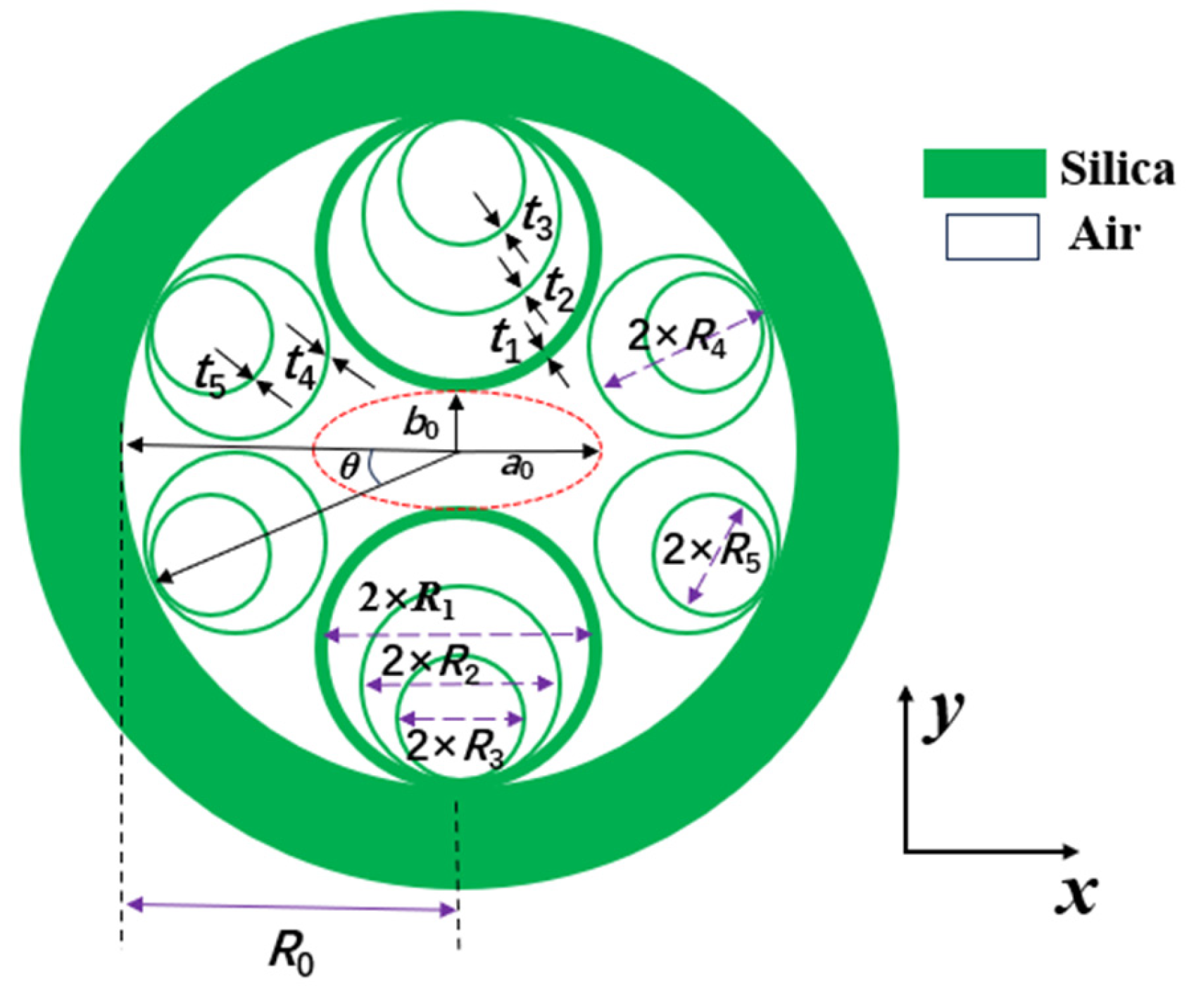
Figure 2.
(a) The effect of changes in R1 on the CL of the x-pol FM, (b) the effect of changes in R1 on the CL of the y-pol FM, (c) the effect of changes in R1 on the birefringence and (d) the FM field patterns calculated at wavelength 1550 nm for R1 values of 13.6 μm, 15 μm, and 15.6 μm, respectively.
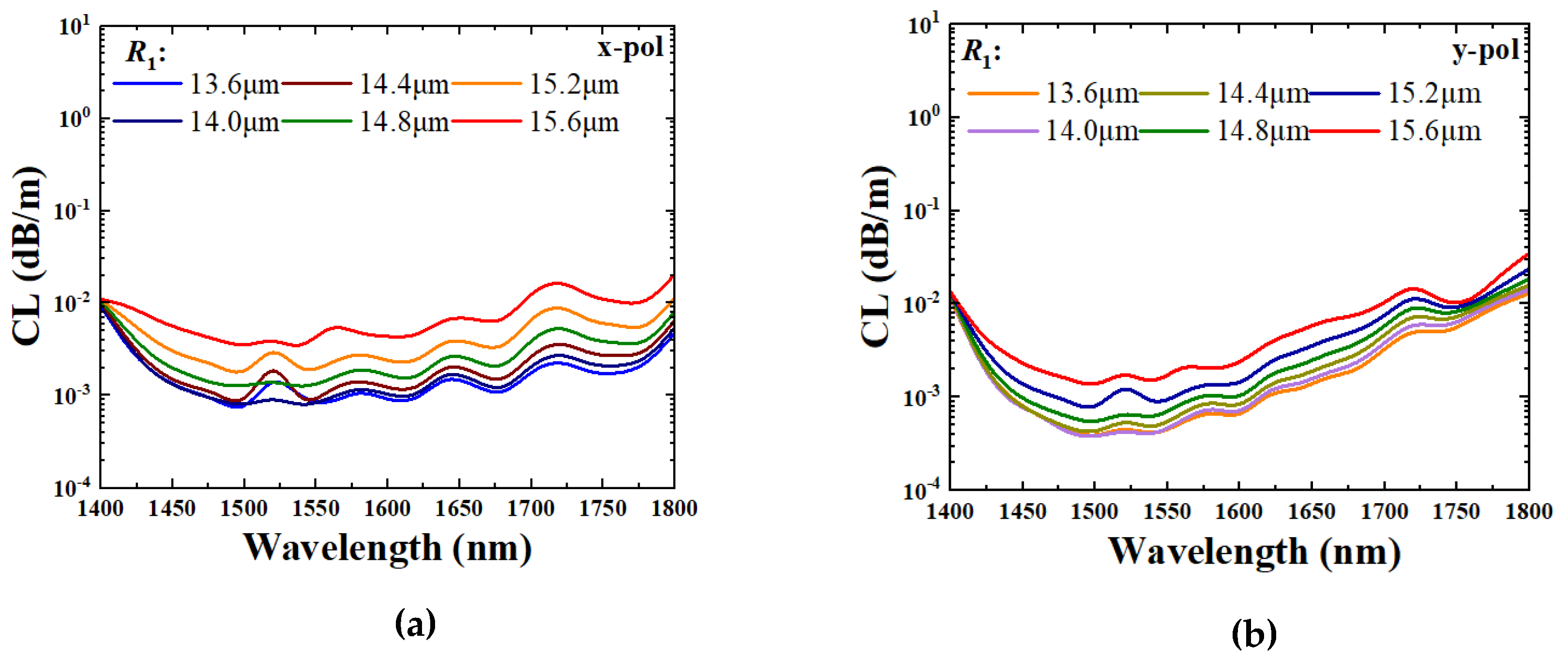
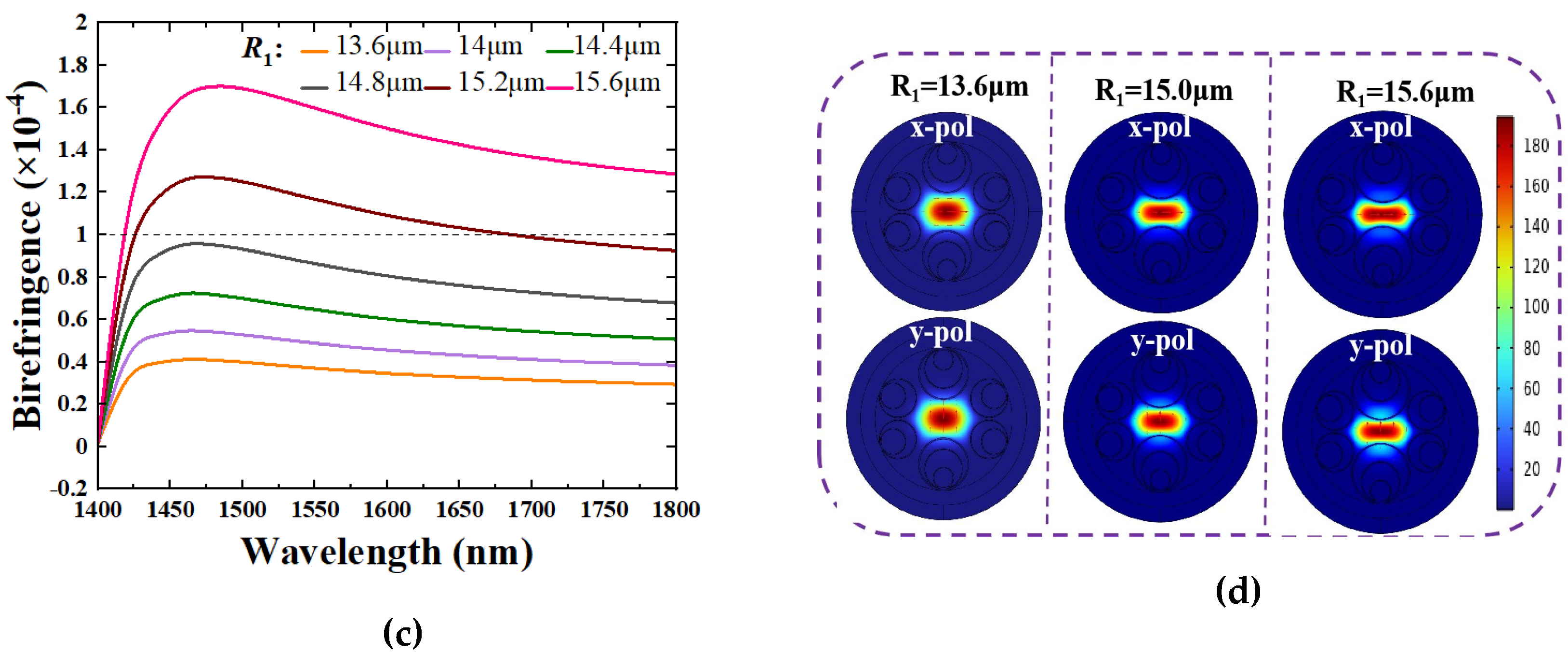
Figure 3.
(a) The effect of k1 on the CL and birefringence, (b) the effect of k2 on the CL and birefringence, (c) the effect of R4 on the CL and birefringence, and (d) the effect of k3 on the CL and birefringence.
Figure 3.
(a) The effect of k1 on the CL and birefringence, (b) the effect of k2 on the CL and birefringence, (c) the effect of R4 on the CL and birefringence, and (d) the effect of k3 on the CL and birefringence.
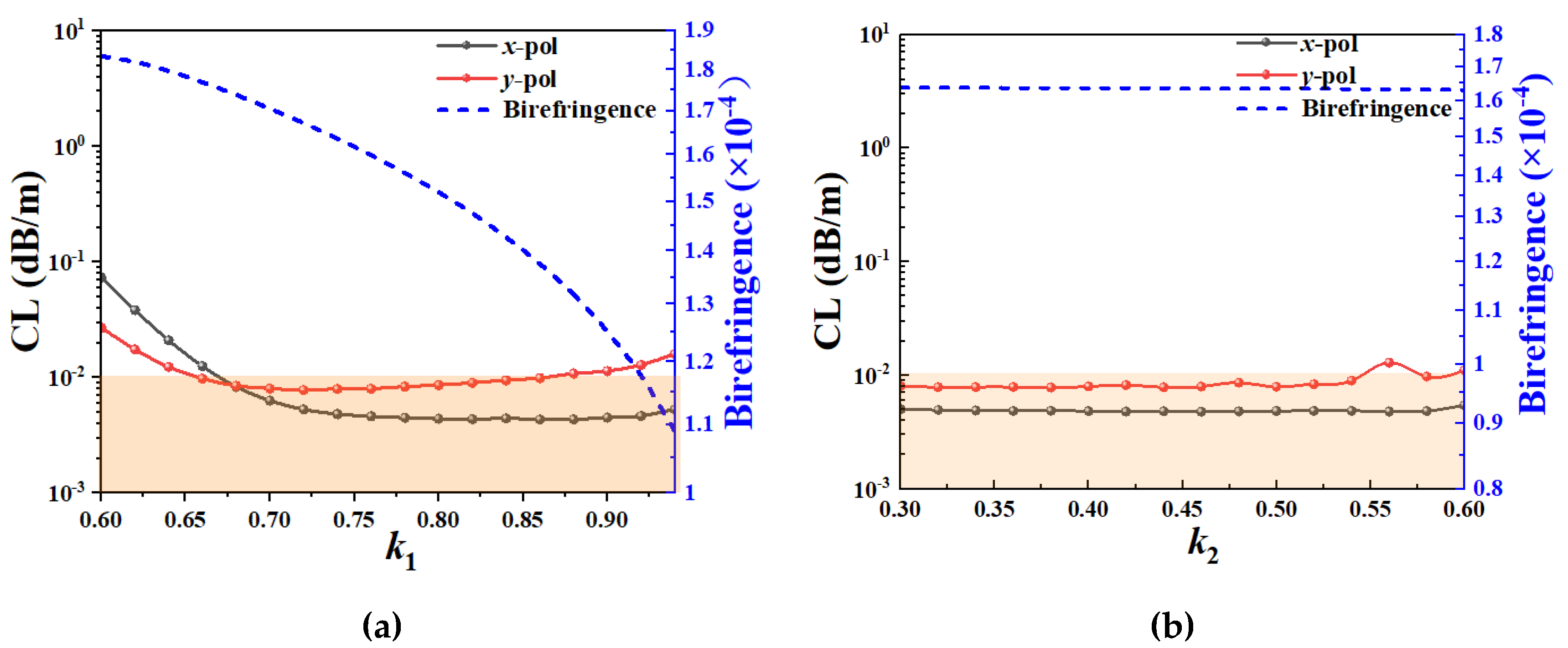
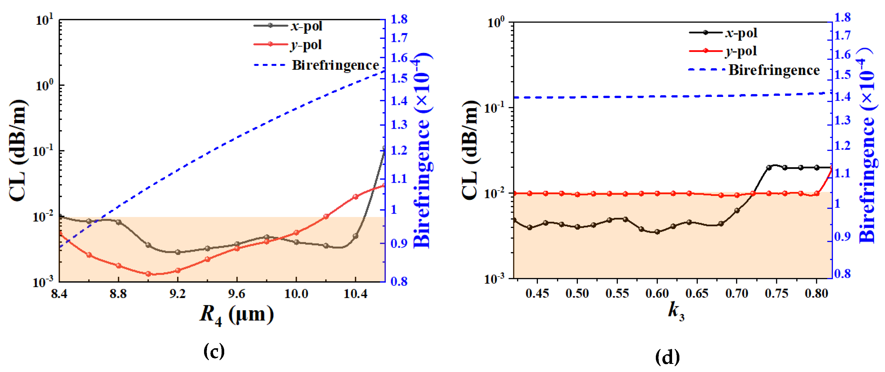
Figure 4.
(a) The effect of t on the CL and birefringence, and (b) the effect of t on the effective refractive index and birefringence.
Figure 4.
(a) The effect of t on the CL and birefringence, and (b) the effect of t on the effective refractive index and birefringence.
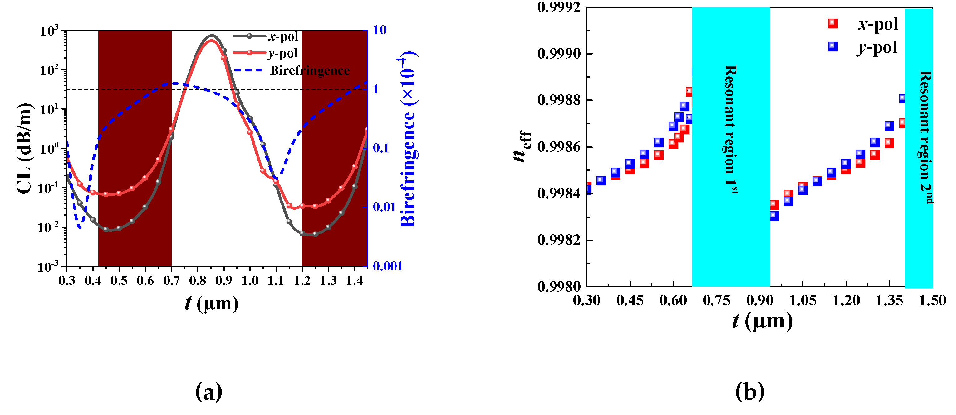
Figure 5.
(a) The effect of t4 on the CL and birefringence, and (b) the effect of t4 on the effective refractive index and birefringence.
Figure 5.
(a) The effect of t4 on the CL and birefringence, and (b) the effect of t4 on the effective refractive index and birefringence.
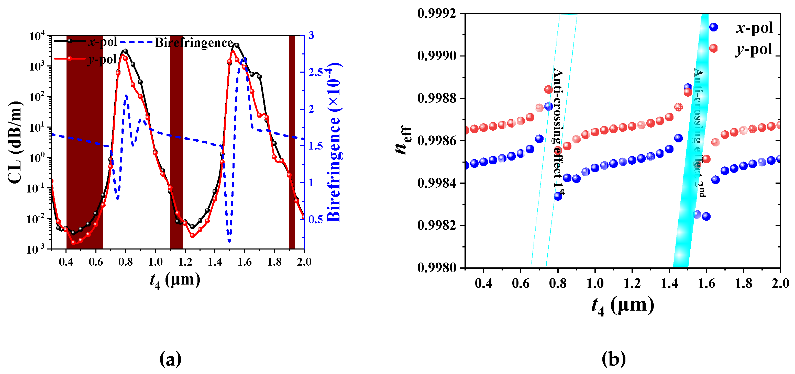
Figure 6.
(a) The x-pol fundamental mode CL and (b) y-pol fundamental mode CL as functions of and , and (c) the birefringence as a function of and at wavelength 1.55 μm.
Figure 6.
(a) The x-pol fundamental mode CL and (b) y-pol fundamental mode CL as functions of and , and (c) the birefringence as a function of and at wavelength 1.55 μm.

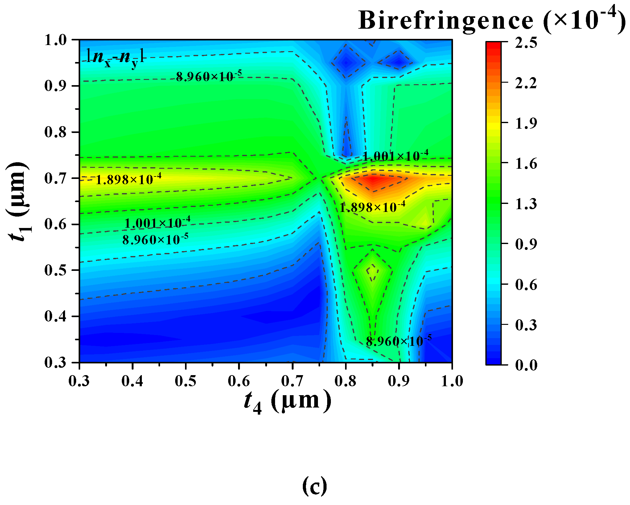
Figure 7.
(a) The effect of t′ on the CL and birefringence, and (b) the electric field distributions of the x-pol and y-pol fundamental modes calculated at wavelength 1.55 μm, along with t′=0.45 μm and t′=0.75 μm.
Figure 7.
(a) The effect of t′ on the CL and birefringence, and (b) the electric field distributions of the x-pol and y-pol fundamental modes calculated at wavelength 1.55 μm, along with t′=0.45 μm and t′=0.75 μm.
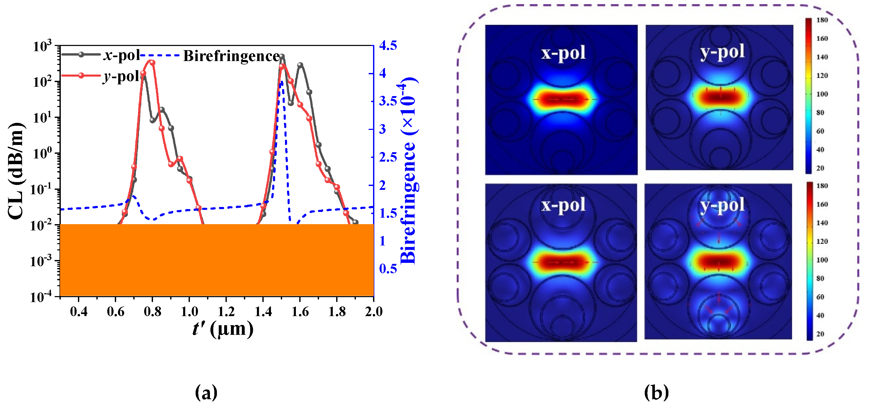
Figure 8.
(a) The x-pol and y-pol fundamental mode CLs as functions of wavelength, (b) the effective refractive indices of the x-pol and y-pol fundamental modes, and birefringence as functions of wavelength, and (c) the electrical field distributions of the x-pol and y-pol fundamental modes calculated at wavelengths 1380 nm and 1550nm.
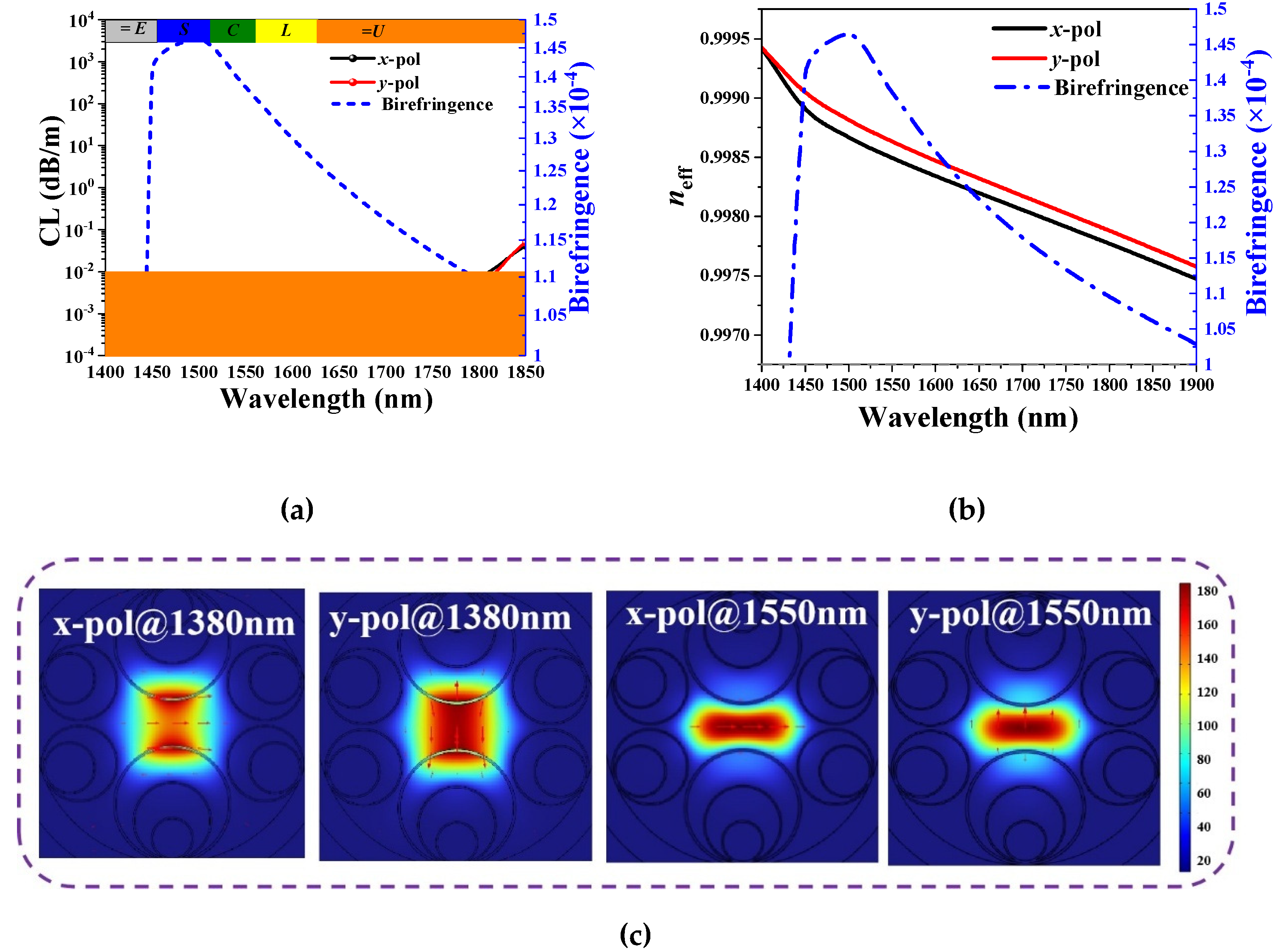
Figure 9.
(a) The CLs of the FM and the HOMs (LP11, LP21, LP31, LP22), (b) the corresponding HOMER and birefringence, and (c) the mode field distributions of the FM and HOMs.
Figure 9.
(a) The CLs of the FM and the HOMs (LP11, LP21, LP31, LP22), (b) the corresponding HOMER and birefringence, and (c) the mode field distributions of the FM and HOMs.
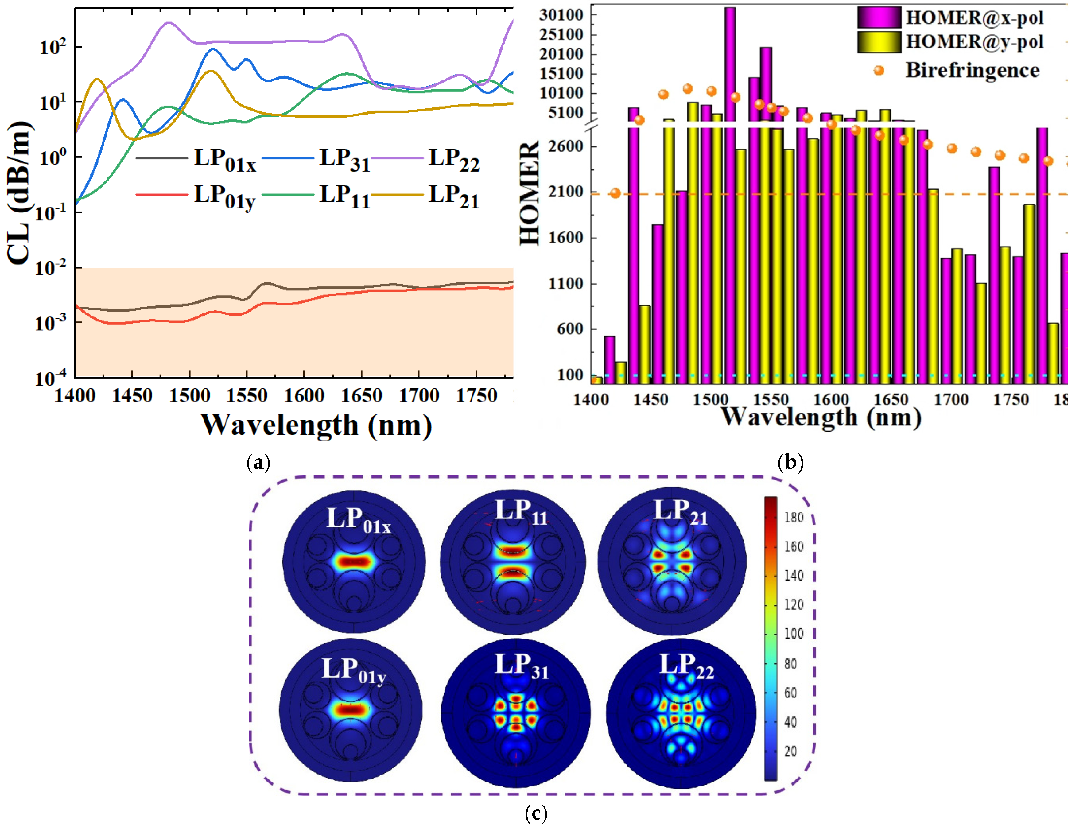
Figure 10.
(a) and (b) The impact of bending radius on various parameters, and (c) mode diagrams with bending of 1 cm and 3 cm, respectively, in the x-direction and 6 cm in the y-direction. ( =74.25μm, =15.6 μm, =10.4 μm, =5.62 μm, =10.2 μm, =6.93 μm, 0.45μm, and =0.67 μm.).
Figure 10.
(a) and (b) The impact of bending radius on various parameters, and (c) mode diagrams with bending of 1 cm and 3 cm, respectively, in the x-direction and 6 cm in the y-direction. ( =74.25μm, =15.6 μm, =10.4 μm, =5.62 μm, =10.2 μm, =6.93 μm, 0.45μm, and =0.67 μm.).
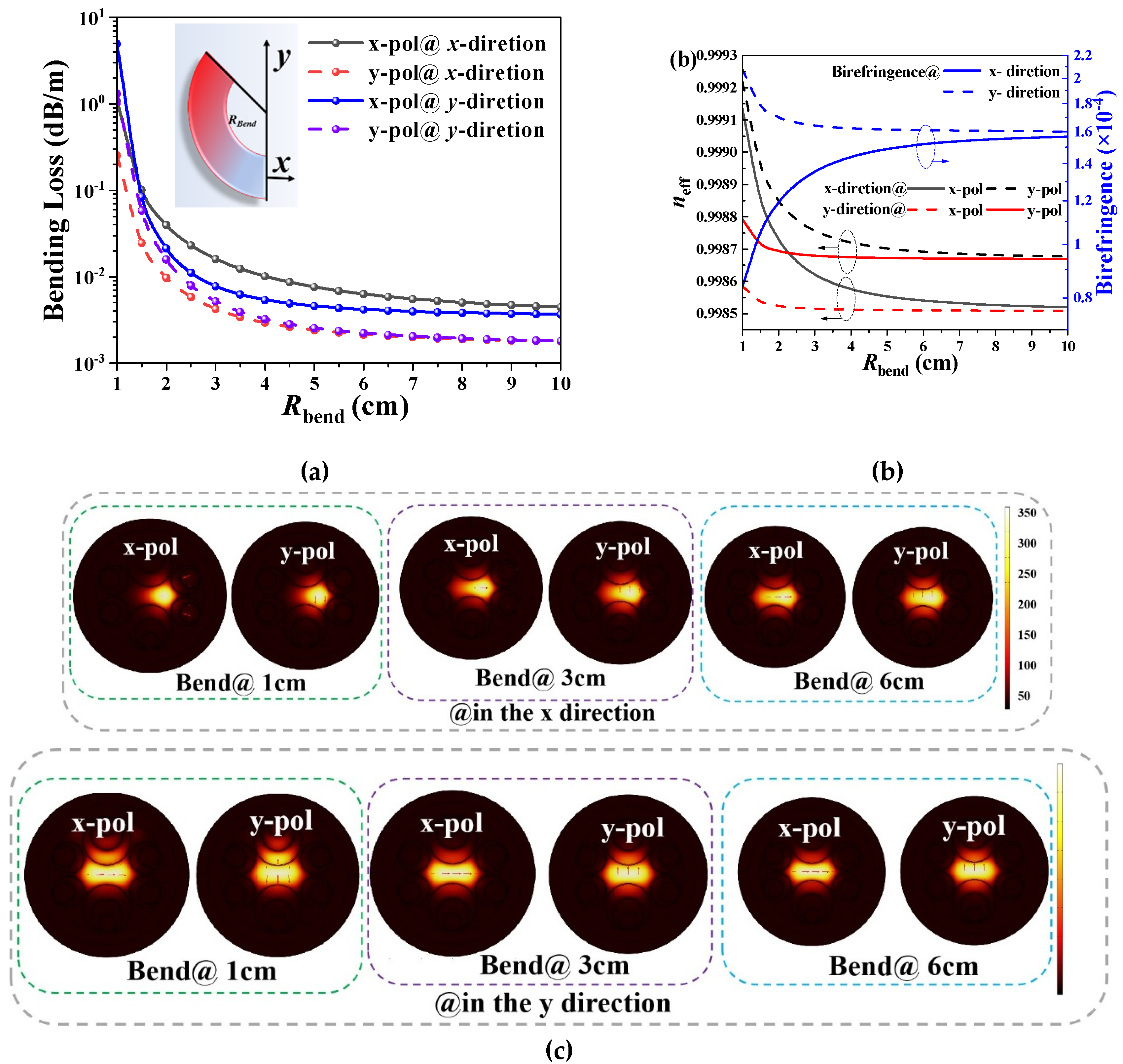

Table 1.
Comparison of the performances of the designed PM-HC-ARF with other reported results.
| Ref. | CL | Birefringence | Bandwidth | Bending resistance |
HOMER |
| [37] | 185.0 dB/km @1.589μm | 9.1 × 10⁻⁵ | 133nm | >10cm | No report |
| [38] | 30dB/km @1.55μm; | >1×10⁻⁴ | 460nm(<103dB/km) | >4cm | No report |
| [39] | 460dB/km @1.55μm | >2.5×10⁻⁵ | 150nm | ------ | No report |
| [40] | 4.8 dB/km@ 1.522μm | >1.8×10⁻⁵ | 154nm | >25cm | No report |
| [41] | 8.5dB/km@1.06μm; 204.1dB/km@1.55μm |
3.62×10⁻⁵; 9.83×10⁻⁵ |
172nm; 216nm |
>10cm | No report |
| This work |
1.5dB/km@1.55μm; 0.82dB/km@1.45μm |
>1.45×10⁻⁴ |
>1.05×10⁻⁴, ~380nm |
>3cm (4.25 dB/km) |
32,070 (>241) |
Disclaimer/Publisher’s Note: The statements, opinions and data contained in all publications are solely those of the individual author(s) and contributor(s) and not of MDPI and/or the editor(s). MDPI and/or the editor(s) disclaim responsibility for any injury to people or property resulting from any ideas, methods, instructions or products referred to in the content. |
© 2025 by the authors. Licensee MDPI, Basel, Switzerland. This article is an open access article distributed under the terms and conditions of the Creative Commons Attribution (CC BY) license (http://creativecommons.org/licenses/by/4.0/).
Copyright: This open access article is published under a Creative Commons CC BY 4.0 license, which permit the free download, distribution, and reuse, provided that the author and preprint are cited in any reuse.


