
Submitted:
28 June 2025
Posted:
30 June 2025
You are already at the latest version
Abstract
Nuclear fuel clad are thin-walled tubes containing fuel pellets generating heat during operation of reactor, and also during dry storage due to decay heat. The clad is subjected to high temperature and high pressure environment during various postulated accident scenarios. As the fuel clad acts as a barrier to radioactive release, the clad burst becomes a critical criteria for its integrity assessment. Clad burst experiments have been carried out by various researchers for various combinations of internal pressure and heating schemes. Several empirical correlations are reported in literature for prediction of clad burst stress as a function of burst temperature. These empirical correlations do not account for variation in heating rates on clad burst behavior. In this work, a new damage model has been used to predict the burst behavior of fuel clad for various heating rates. A new correlation has been proposed which takes into account of the heating rates. It was observed that by increasing the heating rate, the burst temperature gets elevated as the time for accumulation of material damage becomes less. The correlation has also been validated with experimental data from literature. This new correlation can be used in severe accident analysis codes to predict the fuel pin burst phenomenon accurately.
Keywords:
nuclear fuel clad
; zircaloy-4
; damage model
; creep
; clad deformation and burst
; thin-walled tube
; burst correlation
1. Introduction
Analysis of progressive (i.e., time dependent) deformation of fuel bundles, pressure tube, calandria tube and coolant channels of pressurized heavy water reactors (PHWR) is one of the important aspects of severe accident research for these type of reactors. Various types of accident scenarios are postulated during analysis and it must be shown that the barrier to radioactive release is maintained in these scenarios. The fuel clad or fuel pin is the first barrier to radioactive high temperature heat producing oxide fuel pellets. Due to accumulation of fission gas inside the clad and high heat generating pellets, the fuel clad can deform by ballooning when the external surface is not cooled sufficiently during a postulated loss of coolant accident (LOCA) scenario. The objective of this work is to study the ballooning deformation behavior of fuel clad when subjected to different loading conditions such as internal pressure and heating rates producing high temperature in the wall of fuel clad. The burst behavior of clad is often the matter of interest for the safety analysts and hence, this aspect is also investigated in this work.
A typical reactor coolant channel is shown in Figure 1(a), which houses the calandria tube, pressure tube and fuel bundles. The fuel bundles contain several fuel pins, inside which fuel pellets are stacked. In order to simulate the ballooning and burst behavior of fuel clad experimentally, the clad is electrically heated while maintaining the internal pressure during the temperature rise. A typical variation of pressure and temperature at different sections of fuel clad is shown in Figure 1(b). The pressure drop is associated with burst of the clad due to localized creep deformation and damage accumulation. Some of the typical pictures of the burst clads are shown in Figure 1(c).
This paper has been organized into seven sections. After a brief description of the problem, a brief review of relevant literature is provided in Section 2. The material properties used in the finite element (FE) analysis of ballooning and burst behavior of fuel clad are presented in Section 3, followed by the details of FE analysis in Section 4. The results are presented in Section 5, which are followed by a discussion regarding the development of a suitable burst correlation in Section 6. Some of the important conclusions are reported in Section 7.
2. Brief Description of Previous Works from Literature Regarding Clad Deformation and Burst
The creep deformation and the corresponding ballooning and burst behavior of nuclear fuel clad has been studied extensively both experimentally and numerically [1,2,3,4,5,6,7]. Feria et al. [1] and Aragón et al. [2] have studied the ballooning deformation of clad assuming a design basis accident (DBA), i.e., loss of coolant accident (LOCA). They have used the severe accident code FRAPTRAN for simulation of clad deformation behavior. The burst behavior of Fe-based alloy cladding tube was studied under LOCA condition in Ref. [3].
Campello et al. [4] have studied the steady-state creep behavior of Zircaloy-4 claddings under LOCA condition and those of FeCrAl-ODS (oxide dispersion strengthened) cladding has been studied extensively by Narukawa et al. [5]. The deformation and burst behavior of Cr-coated Zircaloy cladding under DBA/LOCA conditions have been studied in Ref. [6,7]. A similar study was also found in the works of Kim et al. [8] and Lee et al. [9].
The validation process of the phenomena of clad ballooning and burst during LOCA conditions has been carried out extensively in Ref. [10,11,12,13], where in-situ test data has been used. The code ‘BISON’ has been used extensively to study the deformation behavior of clad in Ref. [10,11,12,13,14,15]. The details of development and validation of another severe accident code ‘ENIGMA’ (used for prediction of deformation behavior of zirconium-based cladding materials) are presented by Rossiter and Peakman [13].
The deformation and bust behavior of FeCrAl based C26M cladding under simulated LOCA conditions have been studied in Ref. [12]. Garrison et al. [16] studied the burst characteristics of an accident-tolerant FeCrAl cladding under temperature transients. The creep deformation behavior of a nuclear-grade C26M2 FeCrAl alloy accident-tolerant fuel cladding was studied through burst test in Ref. [17].
The results of numerical simulation of an accident tolerant fuel clad deformation during LOCA are presented in Ref. [18]. The thermo-mechanical deformation behavior of Zircaloy-4 clad under simulated post-DNB (departure from nucleate boiling) conditions are presented in Ref. [19]. The ballooning and burst characteristics of chromium-coated Zircaloy clad was studied numerically by Ma et al. [20] and a numerical study of PWR (pressurized water reactor) fuel rod cladding ballooning and burst behavior was presented by Zhang et al. [21].
The deformation and burst characteristics of oxide dispersion–strengthened FeCrAl cladding were studied in Ref. [22,23]. The deformation and burst behavior of Zircaloy-4 cladding tube (with internal hydride) was studied experimentally by Kamerman [24]. He used internal pressure and high temperature loading to characterize the deformation and burst behavior of clad. In-situ deformation measurements of Zircaloy-4 cladding tube under various transient heating conditions and the results of the study of the corresponding strain evolution have been presented by researchers in Ref. [25,26,27,28,29].
Various techniques, such as optical image analysis and digital image correlation (DIC) etc. have been used for accurate measurement of strain during the creep deformation process. An extensive review of the progress of research work concerning the study and modelling of high-temperature thermo-mechanical deformation behaviors of Cr-coated cladding and FeCrAl claddings under LOCA conditions are presented in Ref. [30,31].
The bi-axial creep deformation behavior of thin-walled clads are studied in Ref. [32,33]. The thermal creep fracture of a Zr1%Nb cladding alloy has been studied by Sklenicka et al. [34]. Zircaloy-4 coupons have been irradiated using proton beams and the corresponding irradiation-assisted creep deformation of the alloy has been studied in Ref. [35]. Creep tests on Zircaloy-4 fuel claddings have been conducted by Choi et al. [36] and the corresponding deformation behavior has been studied. Various failure criteria for nuclear fuel cladding, which fail by the mechanism of creep rupture, have been presented in Ref. [37,38].
The phenomenon of hydrogen embrittlement and the associated failure characteristics of Zircaloy-4 cladding have been studied recently by Deng et al. [39]. They have used the damage model (i.e., Gurson-Tverggard-Needleman’s porous plasticity model) to simulate the failure of fuel clad. The influence of assembly structural features of light water reactor on cladding burst behavior under LOCA conditions have been studied by Schappel and Capps [40].
The deformation behavior of fuel clad of Indian PHWR was studied in Ref. [41]. Several burst experiments have been recently carried out in Ref. [42] using Zircaloy-4 fuel clad of Indian PHWR. The above researchers have presented the burst temperature and burst time of fuel clad as a function of burst stress. Chung and Kassner [43] have also presented an extensive experimental database, which contains clad burst data for various pressure magnitudes and heating rate conditions. Rosinger [44] have used this database in their work to predict the failure of Zircaloy-4 fuel sheathing during postulated LOCA conditions.
From a detailed study of literature, it was observed that various types of correlations have been proposed in literature, which are mainly empirical in nature. These correlations usually express clad burst stress as a function of burst temperature, which are exponential decay type, and the constants vary depending upon the material of interest, manufacturing conditions of the clad and the temperature range.
The effect of heating rate on clad burst behavior has not been taken into account explicitly in these correlations. Hence, the objective of this work is to develop a heating-rate-dependent correlation, which can represent the clad burst temperature as a function of applied stress for various heating rates. For this purpose, a material damage based model has been proposed and validated with experimental data available in literature so that the same can be used for its extensive application in the development of an appropriate correlation for predicting the burst behavior of Indian PHWR Zircaloy-4 fuel clad.
3. Material Data Used in Finite Element Analysis of Fuel Clad Deformation
For simulation of burst behavior of nuclear fuel clad, finite element analysis with elastic-plastic-creep constitutive model for the material has been used. The material properties of Zircaloy-4 fuel clad have been used in the simulation. One of the important aspects of material constitutive model is that of creep deformation. For simulation of creep deformation behavior, Norton’s constitutive law has been used, where the rate of creep strain is a function of equivalent stress ‘σ’ and temperature T (in K) as shown in Eq. (1), and, A, n and c, are being the steady-state or secondary creep deformation constants of the material.
To evaluate the parameters of the model, creep experiments have been carried out using Zircaloy-4 as the material of the specimens and the creep strain a function of time has been evaluated at different temperatures and applied stress values. A typical variation of data of creep strain as a function of time is shown in Figure 2.
It can be observed that the creep deformation of the specimens fall predominantly in the secondary range and the onset of tertiary occurs earlier for higher values of applied stress. This is similar to typical creep deformation of similar type of Zirconium based alloys. Using data of tests conducted at several temperatures and stress values, the correlation between creep strain rate (in the secondary regime), as a function of applied stress and temperature, has been evaluated. The details can be found elsewhere [41]. It was also observed that the material constants A, n, and c are dependent on the range of temperature, as this material undergoes phase change at higher temperatures [42]. The values of the material constants A, n, and c are provided in Table 1. These data are used in finite element analysis of fuel clad for simulating the ballooning and burst behavior. The initiation of burst of fuel clad has been simulated with the help of a material damage model, which shall be discussed in later sections.
4. Description of Finite Element Model Used in Simulation of Ballooning and Burst Behavior of Fuel Clad
As discussed in Section-1, the cylindrical fuel clad deforms locally by creep and balloons at a location as shown in Figure 1(c). In order to simulate this deformation behavior, the cylindrical clad has been modelled using axisymmetric analysis. The geometry of the fuel clad is shown in Figure 3(a). The outer diameter of the clad is 15.2 mm and the thickness is 0.4 mm. The FE axisysmmetric model of the clad is shown in Figure 3(b).
The FE mesh contains 8-noded higher order quadratic elements. The loading and boundary conditions for the fuel clad are shown in Figure 3(b). Internal pressure is applied and the clad is subjected to a temperature history as shown in Figure 3(c). This temperature history is similar to those used in experiments as reported in Ref. [42]. The creep material properties used in the FE analysis are shown in Table 1. The results of clad deformation history and associated changes in von Mises equivalent stress and equivalent creep strain values are discussed in detail in next section. In addition, the burst behavior is modelled with the help of a damage model as discussed later.
5. Results of FE Analysis, Prediction of Burst Initiation and Experimental Validation
In this section, the results of clad deformation and creep strain accumulation in the fuel clad are shown for various types of loading conditions (i.e., internal pressure and temperature histories, represented in terms of constant heating rates). Figure 4(a) shows the radial deformation contour of the clad at the time step of 45 seconds for the constant heating rate of 15 °C/s. The internal pressure is 3.1 MPa. The maximum radial deformation is 5.3 mm as can be seen from Figure 4(a). The corresponding contour for von Mises equivalent stress is shown in Figure 4(b) and the maximum value of this parameter is 65 MPa.
It may be noted that the maximum values of von Mises equivalent stress increase with increase in applied magnitude of internal pressure as shown in Figure 4(c). The corresponding creep strain accumulation with time for various combinations of internal pressure and heating rates are shown in Figure 4(d). It may be observed that creep strain accumulation starts after a threshold time of 30 seconds (approximately) as this much time is required for the temperature in the clad to reach 600 °C (approximately) as can be seen from Figure 3(c). The creep deformation becomes significant only after the temperature in the clad exceeds 600 °C, as can be seen from the material constants presented in Table 1.
The creep deformation of Zircaloy-4 clad is insignificant below the temperature of 600 °C. Again, the rate of creep strain accumulation is higher for higher values of internal pressure when the heating rates are similar as can be seen from Figure 4(d). However, when the heating rate is lower, i.e., 12.5 °C/s, the creep strain accumulation in the clad is initially slower, even for higher values of applied internal pressure (i.e., 4 MPa), when compared to the corresponding strain accumulation for 2 MPa internal pressure and 15 °C/s heating rate case. This can be explained based on corresponding temperature history in the clad.
Initially, the temperature in the clad with lower heating rate is less and hence, the creep strain accumulation is less even for higher stress value. However, once temperature exceeds the threshold value, both temperature and stress values contribute to creep strain accumulation and hence, the creep strain increases rapidly for 4 MPa internal pressure when compared to that of clad with 2 MPa internal pressure and 15 °C/s heating rate. Hence, it can be concluded that both heating rate and internal pressure values play a role in creep strain accumulation and the corresponding material damage, which leads to initiation of micro-crack and eventual burst in the clad. However, the process of simulation of creep damage requires information regarding stress triaxiality and creep strain. A model for simulation of clad burst is presented in the following paragraphs.
The process of creep damage accumulation occurs by void growth and coalescence [43,45], and hence, the corresponding damage variable can be described using a model similar to that of Rice & Tracey’s void growth law as presented in Ref. [45]. In this work, a new damage variable ‘D’ is proposed, which is a function of stress triaxiality (i.e., ratio of hydrostatic stress to von Mises equivalent stress ) and the inelastic strain increment as shown in Eq. (2). The cumulative damage variable ‘D’ is obtained by integrating the expression till the instant of clad burst as observed in the experiment. The value of damage variable ‘D’ characterizing burst in the clad is denoted as ‘’ and this value is initially calibrated from experimental data.
Using time-dependent history of von Mises equivalent stress and equivalent creep strain increment as presented in Figure 4c,d, the evolution of damage variable ‘D’ in the Indian PHWR fuel clad is calculated for internal pressure of 2 MPa and the heating rate of 15 °C/s. The corresponding result is shown in Figure 5. The burst of Zircaloy fuel clad corresponding to this loading condition occurs at 45 seconds as reported in the experiment carried out in Ref. [42]. Corresponding to this time and the above loading condition, the critical damage parameter ‘’ has been estimated to be 0.12. This value of critical damage parameter is a material property and hence, it has been used in subsequent FE simulations to predict the burst behavior of Zircaloy-4 fuel clad for various combinations of internal pressure loading and heating rates.
The results of FE simulation for various values of internal pressure ranging from 5 to 10 MPa are shown in Figure 6(a). In these simulations, the heating rate is kept constant at 15 °C/s and the corresponding variation of temperature with time is shown in Figure 3(c). As can be seen from Figure 6(a), the damage parameter accumulates after a threshold time step as it required some time for the wall temperature in the clad to exceed 600 °C.
The damage accumulation occurs in an exponentially increasing manner and corresponding to the critical damage value of 0.12, the time is noted for each magnitude of internal pressure. The corresponding temperature at the instant of simulated clad burst can be found from Figure 3(c) as the heating rate is known. Using the above procedure, the temperature of clad at the instant of burst (called burst temperature) is plotted against the internal pressure applied in the clad (called burst pressure) and this data is shown in Figure 6(b). This variation depends upon heating rate as can be seen from subsequent discussions as the creep damage accumulation depends upon clad temperature history, which is in turn dependent upon the heating rate.
The results of FE simulation have been validated with experimental data from literature [42] and a comparison of the same is shown in Figure 7. The clad burst temperature is plotted as a function of burst pressure (i.e., applied internal pressure) in Figure 7(a) and it can be observed that the burst temperature is inversely dependent upon the burst pressure for a given heating rate (i.e., linear variation of temperature with time). The higher burst pressure induces higher stresses in the clad and hence, the damage accumulation occurs faster, leading to burst at lesser time and hence, lesser temperature.
Similar observation is also seen in Figure 7(b), where the time to clad burst is plotted against burst pressure and the dependence is similar to that of burst temperature. The results of the proposed damage model for both burst temperature vs burst pressure and burst time vs burst pressure are also compared with corresponding experimental data taken from literature [42]. It may be observed that the current damage model is able to model the experimentally observed clad burst behavior very satisfactorily and hence, this serves as a predictive tool in modelling of clad deformation during severe accident scenarios.
Moreover, this damage model can be used to simulate clad burst behavior even for different constant and variable heating rates, which may be encountered during severe accident progression in the reactor core. It may be noted that the researchers use various types of empirical correlations between burst temperature and burst stress, which is not suitable for integrity analysis of fuel clad for variable heating rate scenarios as discussed later. On the other hand, the effect of heating rate on clad bust correlation is absent in the typical empirical correlations as presented in Ref. [42].
These correlations use an exponential decay type correlation between burst temperature and burst stress and the constants usually vary for different temperature zones as these are derived from experimental data corresponding to given loading conditions, and, hence, these may not be applicable in generalized loading scenarios. These limitations have been tackled through this new damage model. Later, a heating rate dependent burst temperature vs burst stress correlation has also been proposed, which shall be very useful for the practitioners and safety analysts.
The effect of heating rate on clad burst behavior has been simulated by varying the heating rate from 15 °C/s to 100 °C/s. Various magnitudes of internal pressure varying from 1 MPa to 10 MPa, have been used in the FE simulation. The typical variations of von Mises equivalent stress and equivalent creep strain with time are shown for the two different heating rates in Figure 8a,b. The creep strain accumulation is faster for higher heating rate as can be seen from Figure 8(b).
Moreover, the internal pressure has also a profound effect on creep strain accumulation. Higher internal pressure produces higher stress values in the clad as can be seen from Figure 8(a) and this in turn leads to faster creep strain accumulation as observed in Figure 8(b). Using the similar principle (as discussed earlier) to calculate burst temperature and burst pressure, the variation of burst temperature as a function of burst pressure for the two different heating rates are evaluated and the corresponding data are presented in Figure 8(c).
It may be noted that the clad burst behavior is highly dependent upon the heating rate. However, as discussed earlier, the effect of heating rate is not considered in the empirical correlations available in literature (example, Ref. [42]), and, hence, this remains a limitations of the existing correlations. For this purpose, a new heating rate dependent correlation has been proposed in this work, which uses the results of the damage model to derive the new correlation.
To elucidate this point, a typical experimental database for burst stress vs burst temperature as taken from Ref. [42] is shown in Figure 9(a). The data points have been fitted with different types of correlations in the different temperature regimes. However, the functional forms of all these correlations remain exponential decay type, with constants deferring for each zone of temperature as shown in Figure 9(a). Another set of experimental data points have been taken from Ref. [43], which shows the variations of clad burst temperature with burst pressure values for two different heating rates in Figure 9(b).
One notable observation in this data is that significant differences in the clad burst temperature vs burst pressure behavior are observed for the two different heating rates of 5 °C/s and 115 °C/s respectively. The higher heating rate produces higher burst temperature for a given applied internal pressure value. This is similar to the results of our FE simulation as discussed earlier and presented in Figure 8(c). In order to quantify the effect of heating rate on burst temperature vs burst pressure behavior of fuel clad, the damage model as developed in this work, has been applied and the results have been correlated to a normalized heating rate as discussed later in detail.
The effect of heating rate on clad burst behavior is also reported in Ref. [44], however, no such correlation linking clad burst temperature to the heating rate and applied stress can be found in literature. Figure 10 shows the variation of burst temperature as a function of initially applied stress (or engineering stress) for different heating rates ranging from 1 °C/s to 100 °C/s. It can be seen from this figure that the heating rates elevate the temperature at the time of clad burst if the applied stress is kept constant.
As the higher heating rate reduces the corresponding time duration for strain accumulation for a given temperature range, the creep damage accumulation becomes less for this temperature range and hence, a higher temperature is required for creep damage accumulation to reach the desired critical magnitude, which in-turn initiate micro-crack and corresponding burst in the clad. Using the material data for Indian PHWR fuel clad as presented in Table 1, FE simulations have been carried out for different heating rates ranging from 5 °C/s to 100 °C/s.
The corresponding initial stress values (controlled with the help of internal pressure) have been varied from 1 MPa to 180 MPa covering a very wide range of applied stress and heating rates. The results of burst temperature and initial stress are plotted in Figure 11 for different heating rates varying from slow heating rate of 5 °C/s to a very fast heating rate of 100 °C/s. The results show an inverse type dependence of burst temperature on initial stress for a fixed heating rate and with increased heating rate, the burst temperature becomes more for a given applied stress. This is similar to our earlier discussion of corresponding results from literature, however, this result corresponds to the material properties of Indian PHWR fuel clad and this has been predicted through our proposed damage model.
6. Discussion
As discussed earlier, the finite element based damage model can be used to predict the clad burst behavior for any type of high temperature loading scenarios. It can also simulate the heating rate effect on clad burst behavior or in other words, the effect of temperature history (either linear or nonlinear variation with time) is inbuilt in the formulation. This model has also been validated against experimental data as presented in Figure 7. However, for simplicity and ease of use for the practitioners, a new heating rate dependent correlation has been developed additionally in this work using the new damage model. This type of correlation is also helpful for severe accident codes, which rely on its simplicity in order to perform simulations of severe accident progression of core components efficiently.
Initially, the heating rate of 5 °C/s has been chosen as the reference heating rate, as this is one of the lowest heating rates encountered in a typical experimental data for heating rate in literature. This reference data shall be used later to develop the heating rate dependent clad burst correlation. Figure 12(a) shows the variation of burst temperature (Tb) vs engineering burst stress (same as the initially applied equivalent stress) for the reference heating rate of 5 °C/s. The data points have been fitted with a correlation as shown in Figure 12(a).
Later, similar simulations have been carried out for several heating rates varying from 15 °C/s to 100 °C/s. The corresponding burst temperature vs engineering burst stress data have been used to derived the normalized burst temperature, expressed as , where denotes the burst temperature for any heating rate and corresponds to the burst temperature for the reference heating rate of 5 °C/s. The variation of the normalized burst temperature with burst stress is shown in Figure 12(b).
It can be observed that this normalized burst temperature is almost independent of the applied engineering burst stress. However, the normalized burst temperature increases with heating rate as can be seen from Figure 12(b). Later, the heating rate has also been normalized with the reference data, corresponding to that of 5 °C/s heating rate. The normalized heating rate is defined as , where is the actual heating rate in °C/s and corresponds to the reference heating rate of 5 °C/s.
The variation of with is shown in Figure 12(c). The data points from simulation have been fitted with a correlation as shown in Figure 12(c). Hence, the new heating rate dependent clad burst correlation as developed in this work can be summarized as follows in Eq. (3) below.
In order to use this correlation, the use first calculates the value of as a function of . Later using information regarding heating rate and reference heating rate = 5 °C/s, the value of normalized burst temperature is calculated from which the actual clad burst temperature can be calculated using first line of Eq. (3).
7. Conclusions
In this work, the ballooning and burst behavior of nuclear fuel clad due to high temperature creep deformation and associated damage accumulation has been investigated using a material damage model. This model can predict the burst temperature as a function of burst stress for different heating rates. In addition, a new correlation has also been developed based on the results of new damage model, which can predict the burst behavior of clad as a function of heating rate. Such kinds of burst correlations are not available in the literature. The following conclusions can be derived from this work.
- The creep damage accumulation depends upon the history of temperature and stress variation in the clad and the stress triaxiality in the clad is an important factor, which promotes creep damage accumulation in the material.
- For a given heating rate, higher applied pressure results in lower temperature at clad burst as the applied stress is higher, which can lead to higher creep strain accumulation at a given temperature.
- A threshold magnitude of burst time and burst temperature is observed, both in experimental data from literature, and from the results of the current simulation, which corresponds to the clad temperature of the order of 600 °C approximately. This corresponds to the temperature below which creep deformation of Indian PHWR Zircaloy-4 fuel clad is negligible.
- Clad burst temperature increases with heating rate for a given value of applied stress. This can be explained based on temperature variation with time for different heating rates. For higher heating rate, there is less time available for creep deformation at a given temperature range and hence, the clad needs to attain higher temperature in order to accumulate creep damage corresponding to the critical value needed for initiation of clad burst.
- A new heating rate dependent correlation has been developed in this work, which can be used by the practitioners as well as by the engineers using the severe accident analysis program in order to simulate the clad deformation and burst behavior in a realistic manner, when heating rate varies during the accident progression.
Author Contributions
Conceptualization, MKS; methodology, AS, MKS; software, AS; validation, AS, MKS; formal analysis, AS, MKS; investigation, AS, MKS; resources, MKS; data curation, AS, MKS; writing—original draft preparation, AS, MKS; writing—review and editing, MKS; visualization, AS; supervision, MKS; project administration, MKS; funding acquisition, Not Applicable.
Funding
This research received no external funding.
Data Availability Statement
Data shall be available on request.
Acknowledgments
The authors acknowledge the support of Head, Reactor Safety Division, Bhabha Atomic Research Centre, Mumbai, India for his kind encouragement for this research.
Conflicts of Interest
The authors declare no conflicts of interest.
References
- Feria F., Aragón P., Herranz L.E. Assessment of cladding ballooning during DBA-LOCAs with FRAPTRAN. Annals of Nuclear Energy. 195, 2024, 110194. [CrossRef]
- Aragón P., Feria F., Herranz L.E., Schubert A., Uffelen P.V. Enhancing cladding mechanical modelling during DBA/LOCA accidents with FRAPTRAN: The TUmech one-dimensional model. Progress in Nuclear Energy, 171, 2024, 105189. [CrossRef]
- Massey C.P., Terrani K.A., Dryepondt S.N., Pint B.A. Cladding burst behavior of Fe-based alloys under LOCA. Journal of Nuclear Materials, 470, 2016, pp. 128-138. [CrossRef]
- Campello D., Tardif N., Moula M., Baietto M.C., Coret M., Desquines J. Identification of the steady-state creep behavior of Zircaloy-4 claddings under simulated Loss-Of-Coolant Accident conditions based on a coupled experimental/numerical approach. International Journal of Solids and Structures, 115–116, 2017, pp. 190-199. [CrossRef]
- Narukawa T., Kondo K., Fujimura Y., Kakiuchi K., Udagawa Y., Nemoto Y. Behavior of FeCrAl-ODS cladding tube under loss-of-coolant accident conditions. Journal of Nuclear Materials, 582, 2023, 154467. [CrossRef]
- Aragón P., Feria F., Herranz L.E., Schubert A., Uffelen P.V. Fuel performance modelling of Cr-coated Zircaloy cladding under DBA/LOCA conditions. Annals of Nuclear Energy, 211, 2025, 110950. [CrossRef]
- Sweet R., Mouche P., Bell S., Kane K., Capps N. Chromium-coated cladding analysis under simulated LOCA burst conditions. Annals of Nuclear Energy, 176, 2022, 109275. [CrossRef]
- Kim J., Yoon J.W., Kim H., Lee S.-U. Prediction of ballooning and burst for nuclear fuel cladding with anisotropic creep modeling during Loss of Coolant Accident (LOCA). Nuclear Engineering and Technology, 53(10), 2021, pp. 3379-3397. [CrossRef]
- Li W., Chen H., Wu X., Duan Q., Su G.H. Simulation of nuclear fuel clad high-temperature ballooning under loss-of-coolant accident conditions considering anisotropic creep. Annals of Nuclear Energy. 203, 2024, 110500. [CrossRef]
- Capps N., Ridley M., Yan Y., Bell S., Kane K. BISON validation to in situ cladding burst test and high-burnup LOCA experiments, Annals of Nuclear Energy. 191, 2023, 109905. [CrossRef]
- Pastore G., Williamson R.L., Gardner R.J., Novascone S.R., Tompkins J.B., Gamble K.A., Hales J.D. Analysis of fuel rod behavior during loss-of-coolant accidents using the BISON code: Cladding modeling developments and simulation of separate-effects experiments. Journal of Nuclear Materials, 543, 2021, 152537. [CrossRef]
- Sweet R.T., Massey C.P., Hirschhorn J.A., Bell S.B., Kane K.A. Wrought FeCrAl alloy (C26M) cladding behavior and burst under simulated loss-of-coolant accident conditions. Nuclear Engineering and Design, 431, 2025, 113712. [CrossRef]
- Lee S.K., Capps N.A., Brown N.R. BISON analysis of FeCrAl and Zircaloy cladding deformation during simulated BWR cyclic dry-out conditions. Journal of Nuclear Materials, 576, 2023, 154243. [CrossRef]
- Rossiter G., Peakman A. Development and validation of Loss of Coolant Accident (LOCA) simulation capability in the ENIGMA fuel performance code for zirconium-based cladding materials. Nuclear Engineering and Design, 416, 2024, 112767. [CrossRef]
- Verma L., Clifford I., Konarski P., Scolaro A., Ferroukhi H. Offbeat V&V studies for REBEKA tests on cladding ballooning and burst during LOCA conditions. Annals of Nuclear Energy, 208, 2024, 110773. [CrossRef]
- Garrison B., Cinbiz M.N., Gussev M., Linton K. Burst characteristics of advanced accident-tolerant FeCrAl cladding under temperature transient testing. Journal of Nuclear Materials, 560, 2022, 153488. [CrossRef]
- Joshi P., Kombaiah B., Cinbiz M.N., Murty K.L. Characterization of stress-rupture behavior of nuclear-grade C26M2 FeCrAl alloy for accident-tolerant fuel cladding via burst testing. Materials Science and Engineering A, 791, 2020, 139753. [CrossRef]
- Kane K., Bell S., Capps N., Garrison B., Shapovalov K., Jacobsen G., Deck C., Graening T., Koyanagi T., Massey C. The response of accident tolerant fuel cladding to LOCA burst testing: A comparative study of leading concepts. Journal of Nuclear Materials, 574, 2023, 154152. [CrossRef]
- Jailin T., Tardif N., Desquines J., Chaudet P., Coret M., Baietto M.-C., Georgenthum V. Thermo-mechanical behavior of Zircaloy-4 claddings under simulated post-DNB conditions. Journal of Nuclear Materials, 531, 2020, 151984. [CrossRef]
- Ma Z., Shirvan K., Wu Y., Su G.H. Numerical investigation of ballooning and burst for chromium coated zircaloy cladding. Nuclear Engineering and Design, 383, 2021, 111420. [CrossRef]
- Zhang X., Li G., Gao R., Zhao X., Yao P. Numerical study on PWR fuel rod cladding ballooning and burst behavior with the thermo-mechanical coupling finite element method. International Journal of Advanced Nuclear Reactor Design and Technology, 7(1), 2025, pp. 7-18. [CrossRef]
- Yano Y., Sekio Y., Tanno T., Kato S., Inoue T., Oka H., Ohtsuka S., Furukawa T., Uwaba T., Kaito T., Ukai S. Ultra-high temperature creep rupture and transient burst strength of ODS steel claddings. Journal of Nuclear Materials, 516, 2019, pp. 347-353. [CrossRef]
- Massey C.P., Kane K.A., Sweet R.T., Bell S.B., Dryepondt S.N., Burns J., Nelson A.T. Microstructure dependent burst behavior of oxide dispersion–strengthened FeCrAl cladding. Materials and Design, 234, 2023, 112307. [CrossRef]
- Kamerman D. The deformation and burst behavior of Zircaloy-4 cladding tubes with hydride rim features subject to internal pressure loads. Engineering Failure Analysis, 153, 2023, 107547. [CrossRef]
- Bell S.B., Kane K.A., Ridley M.J., Garrison B.E., Johnston B.S., Capps N.A. In-situ determination of strain during transient burst testing and the temperature dependence of Zircaloy-4 claddings. Journal of Nuclear Materials, 591, 2024, 154910. [CrossRef]
- Choi G.-H., Kim D.-H., Shin C.-H., Kim J.Y., Kim B.J. In-situ deformation measurement of Zircaloy-4 cladding tube under various transient heating conditions using optical image analysis. Nuclear Engineering and Design, 370, 2020, 110859. [CrossRef]
- Gussev M.N., Byun T.S., Yamamoto Y., Maloy S.A., Terrani K.A. In-situ tube burst testing and high-temperature deformation behavior of candidate materials for accident tolerant fuel cladding. Journal of Nuclear Materials, 466, 2015, Pages 417-425. [CrossRef]
- Kim D.-H., Choi G.-H., Kim H., Lee C., Lee S.-U., Hong J.-D., Kim H.-S. Measurement of Zircaloy-4 cladding tube deformation using a three-dimensional digital image correlation system with internal transient heating and pressurization. Nuclear Engineering and Design, 363, 2020, 110662. [CrossRef]
- Ridley M., Massey C., Bell S., Capps N. High temperature creep model development using in-situ 3-D DIC techniques during a simulated LOCA transient. Annals of Nuclear Energy, 193, 2023, 110012. [CrossRef]
- Yin C., Su G., Qian L., Xiong Q., Liu Y., Wu Y., Sijia Du S., Jing Zhang J., Zhong Xiao Z. Research progress in high-temperature thermo-mechanical behaviors for modelling Cr-coated cladding under loss-of-coolant accident condition. Nuclear Engineering and Design, 439, 2025, 114125. [CrossRef]
- Qian L., Liu Y., Huang T., Chen W., Du S., Yin C., Xiong Q. Research progress in high-temperature thermo-mechanical behavior for modelling FeCrAl cladding under loss-of-coolant accident condition. Progress in Nuclear Energy, 164, 2023, 104848. [CrossRef]
- Murty K.L., Seok C.S., Kombaiah B. Burst and biaxial creep of thin-walled tubing of low c/a-ratio HCP metals. Procedia Engineering, 55, 2013, pp. 443-450. [CrossRef]
- Xin J., Yuyu L., Libin Z. Thermal creep behavior of CZ cladding under biaxial stress state. Nuclear Engineering and Technology, 52(12), 2020, pp. 2901-2909. [CrossRef]
- Sklenicka V., Kral P., Kucharova K., Kvapilova M., Dvorak J., Kloc L. Thermal creep fracture of a Zr1%Nb cladding alloy in the α and (α+β) phase regions, Journal of Nuclear Materials, 553, 2021, 152950. [CrossRef]
- Moore B., Topping M., Long F., Daymond M.R. Stress and temperature dependence of irradiation creep in Zircaloy-4 studied using proton irradiation. Journal of Nuclear Materials, 603, 2025, 155383. [CrossRef]
- Choi G.-H., Shin C.-H., Kim, J.Y. Kim B.J. Circumferential steady-state creep test and analysis of Zircaloy-4 fuel cladding. Nuclear Engineering and Technology, 53, Issue 7, 2021, pp. 2312-2322. [CrossRef]
- Limon R., Lehmann S. A creep rupture criterion for Zircaloy-4 fuel cladding under internal pressure. Journal of Nuclear Materials, 335(3), 2004, pp. 322-334. [CrossRef]
- Han M., Liu H., Zhang W., Zhang Y., Luo S. A failure criterion for nuclear fuel cladding due to internal gas. Nuclear Engineering and Design, 434, 2025, 113909. [CrossRef]
- Deng Y., Liao, H. He Y., Yin Y., Pellegrini M., Su G., Okamoto K., Wu Y. Investigation on hydrogen embrittlement and failure characteristics of Zr-4 cladding based on the GTN method. Nuclear Materials and Energy, 36, 2023, 101463. [CrossRef]
- Schappel D., Capps N. Impact of LWR assembly structural features on cladding burst behavior under LOCA conditions. Nuclear Engineering and Design, 418, 2024, 112887. [CrossRef]
- Syed A., Samal M.K., Chattopadhyay J. Determination of critical material damage parameter for Indian clad tube burst behavior under severe accident scenario. Procedia Structural Integrity, 60, 2024, pp. 195-202. [CrossRef]
- Sawarn, T.K., Banerjee, S., Pandit, K.M., Anantharaman, S. Study of clad ballooning and rupture behavior of fuel pins of Indian PHWR under simulated LOCA condition. Nuclear Engineering & Design 280, 2014, pp. 501–510. [CrossRef]
- Chung H.M., Kassner T.F. Deformation characteristics of Zircaloy cladding in vacuum and steam under transient heating conditions. Report No. NUREG/CR-0344, ANL-77-31, Argonne National Laboratory, Argonne, Illinois, USA, July 1978.
- Rosinger H.E. A model to predict the failure of Zircaloy-4 fuel sheathing during postulated LOCA conditions. Journal of Nuclear Materials, 120, 1984, pp. 41-54.
- Rice, J.R., Tracey, D.M. On the ductile enlargement of voids in triaxial stress fields. Journal of the Mechanics and Physics of Solids 17, 1969, pp. 201-217.
Figure 1.
(a) Schematic arrangement of fuel pins and fuel bundles inside the pressure tube enclosed by calandria tube in a typical pressurized heavy water reactor and the loading condition of fuel clad; (b) Typical variation of temperature in different regions of clad tube during clad burst experiment and corresponding time variation of internal pressure; (c) Typical localized balooning and burst of clad tube in the experiment.
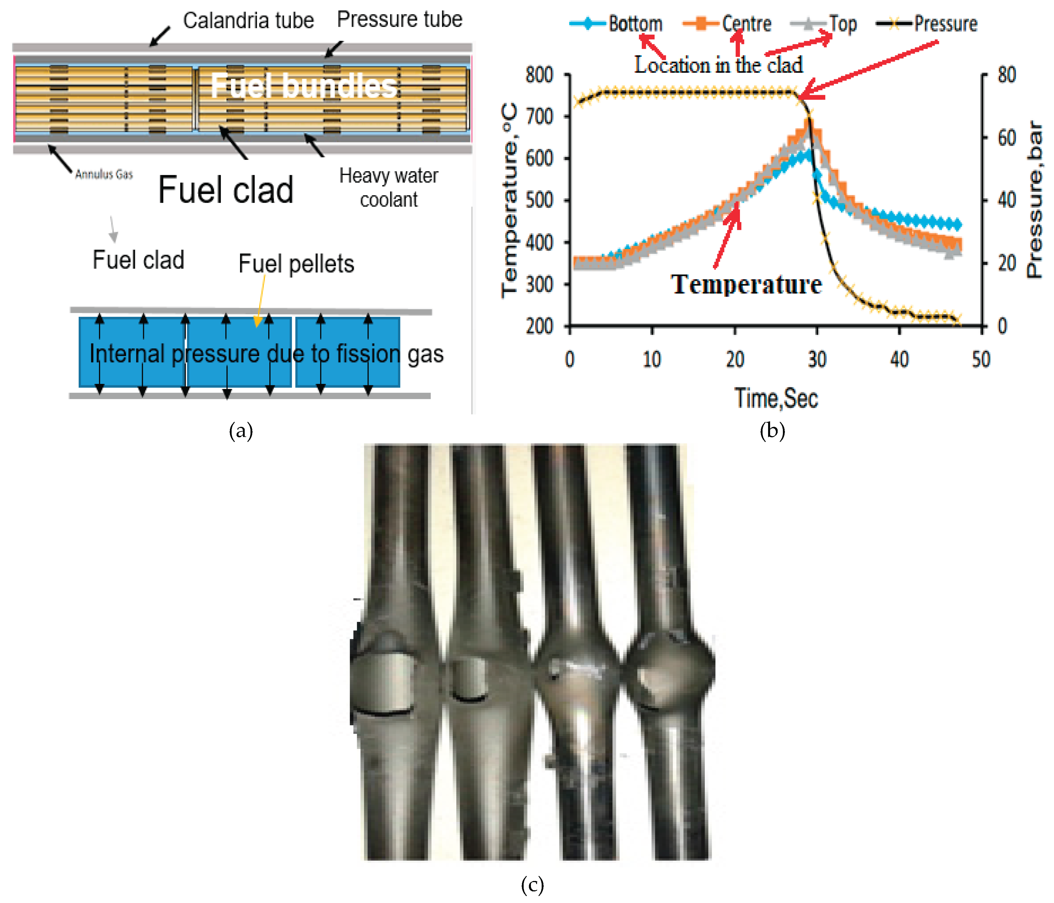
Figure 2.
Variation of creep strain as a function of time for Zircaloy-4 fuel clad of Indian PHWR as obtained from experiment.
Figure 2.
Variation of creep strain as a function of time for Zircaloy-4 fuel clad of Indian PHWR as obtained from experiment.
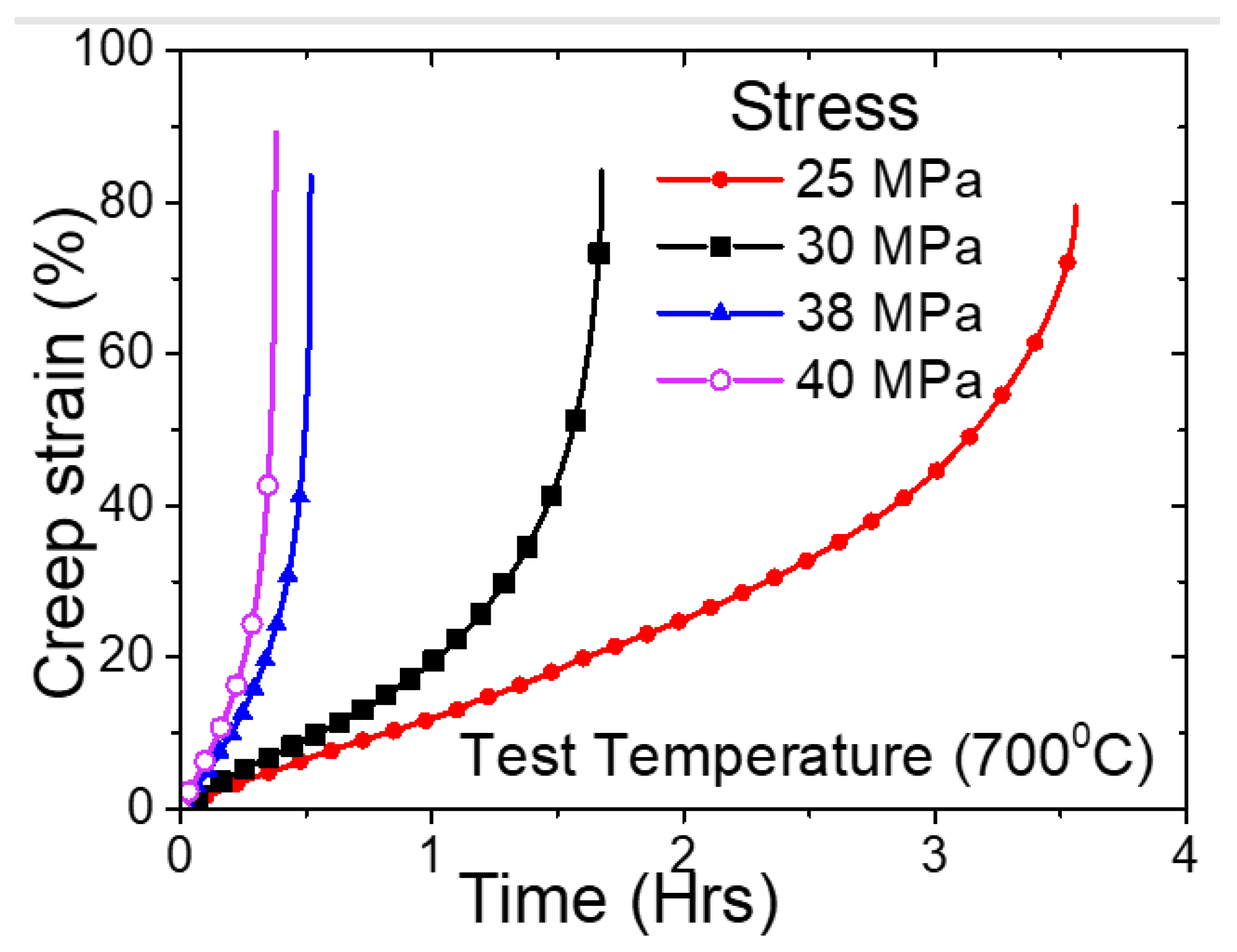
Figure 3.
(a) Geometry of fuel clad of Indian PHWR used in the finite element analysis; (b) Axisymmetric finite element model of fuel clad with internal pressure; (c) Typical variation of temperature of clad a function of time during burst test for two specified heating rates.
Figure 3.
(a) Geometry of fuel clad of Indian PHWR used in the finite element analysis; (b) Axisymmetric finite element model of fuel clad with internal pressure; (c) Typical variation of temperature of clad a function of time during burst test for two specified heating rates.
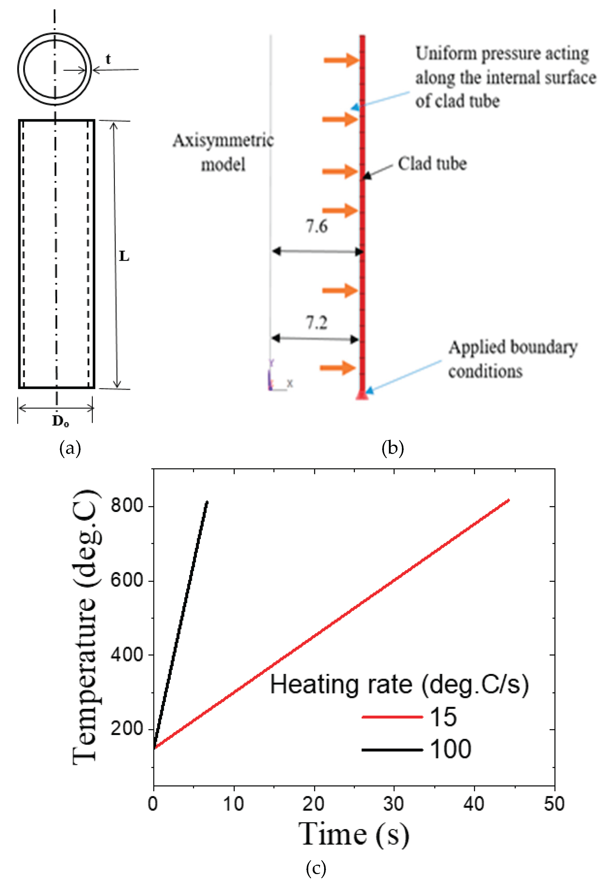
Figure 4.
(a) Results of radial deformation profile of the fuel clad as obtained from FE simulation showing balooning behavior; (b) Contour of von Mises stress in the axisymmetric model of fuel clas for simulation at an internal pressure of 3.1 MPa; (c) Variation of von Mises stress at the maximum location as a function of time for variation values of internal pressure ranging from 1 to 5 MPa and heating rate of 15 °C/s; (d) Variation of equivalent creep strain with time for variation combinations of internal pressure and heating rates.
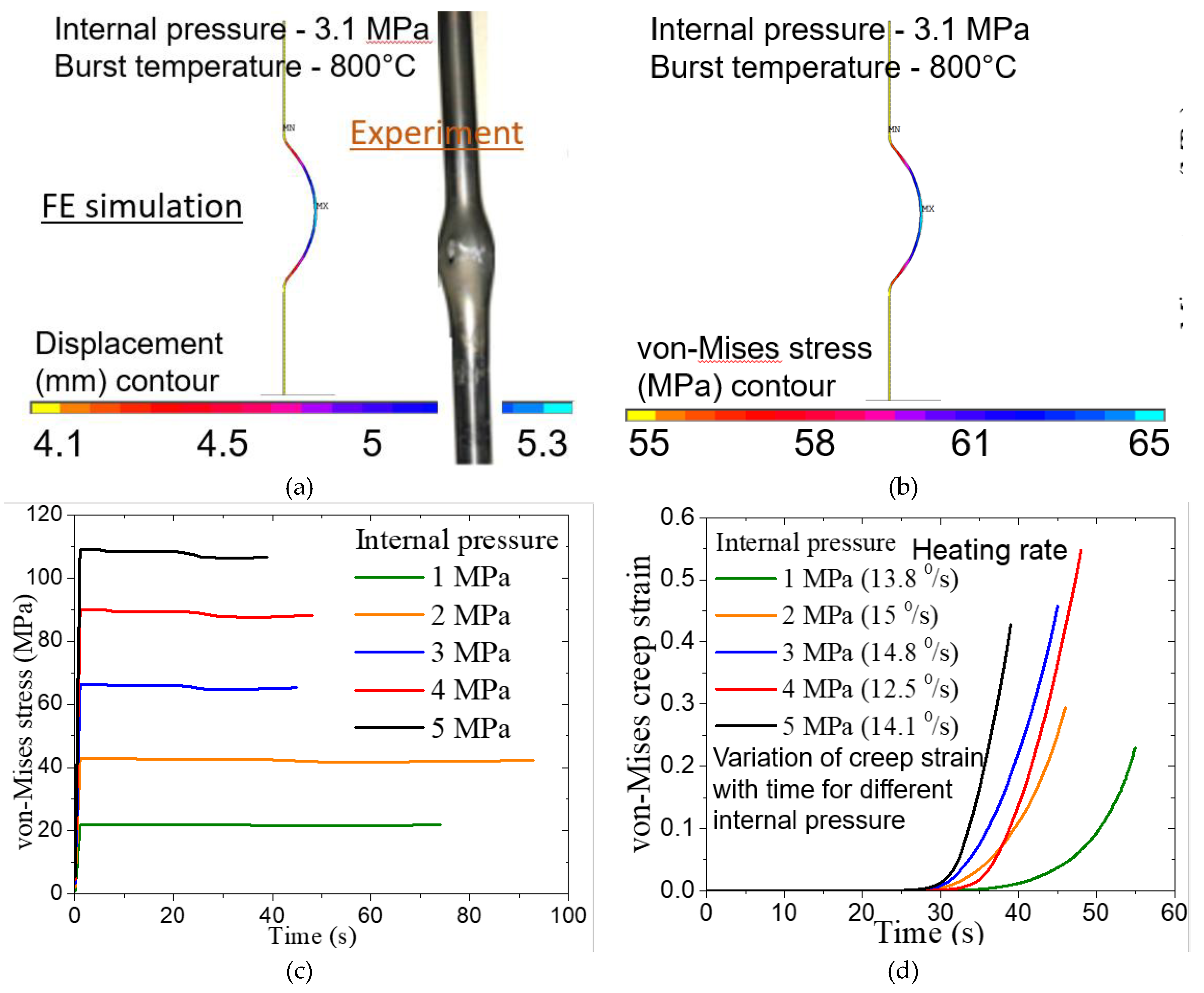
Figure 5.
Evolution of damage parameter ‘D’ as a function of time as obtained from FE simulation for an internal pressure of 2 MPa and determination of critical value from time of clad burst as observed in experiment.
Figure 5.
Evolution of damage parameter ‘D’ as a function of time as obtained from FE simulation for an internal pressure of 2 MPa and determination of critical value from time of clad burst as observed in experiment.
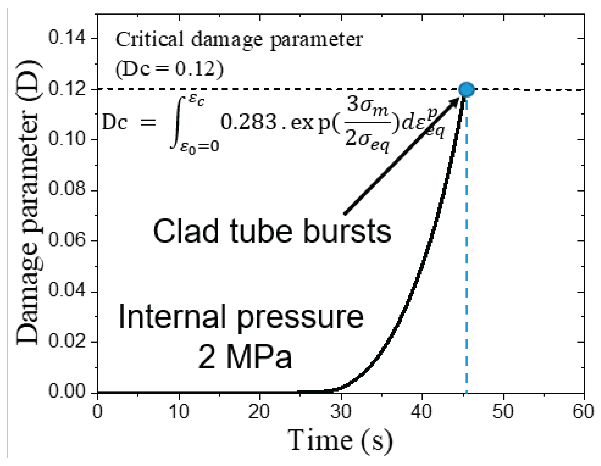
Figure 6.
(a) Variation of damage parameter with time for different values of internal pressure in the clad; (b) Variation of temperature at instant of burst (i.e., corresponding to attainment of critical damage paramter in the FE simulation) as a function of burst pressure.
Figure 6.
(a) Variation of damage parameter with time for different values of internal pressure in the clad; (b) Variation of temperature at instant of burst (i.e., corresponding to attainment of critical damage paramter in the FE simulation) as a function of burst pressure.
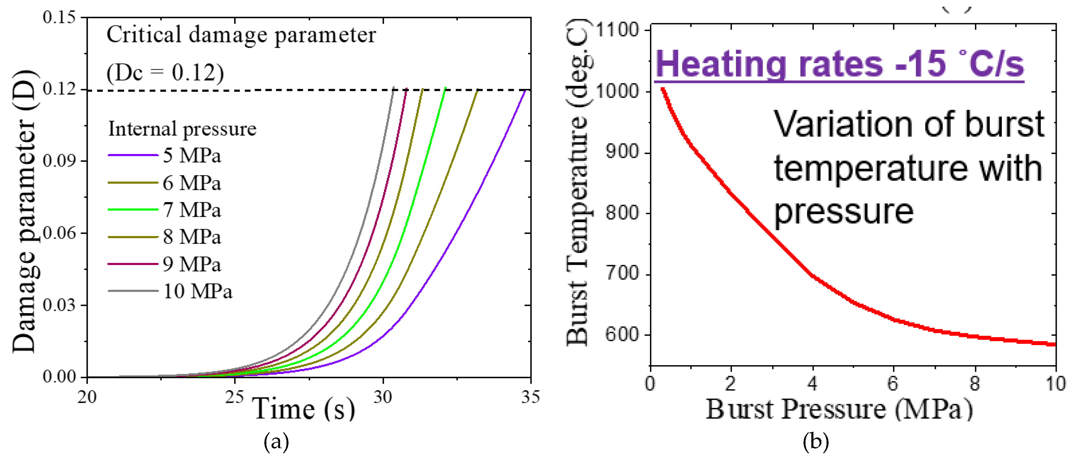
Figure 7.
Comparison of predicted (a) burst temperature vs burst pressure data and (b) burst time vs burst pressure data with corresponding experimental data taken from literature.
Figure 7.
Comparison of predicted (a) burst temperature vs burst pressure data and (b) burst time vs burst pressure data with corresponding experimental data taken from literature.
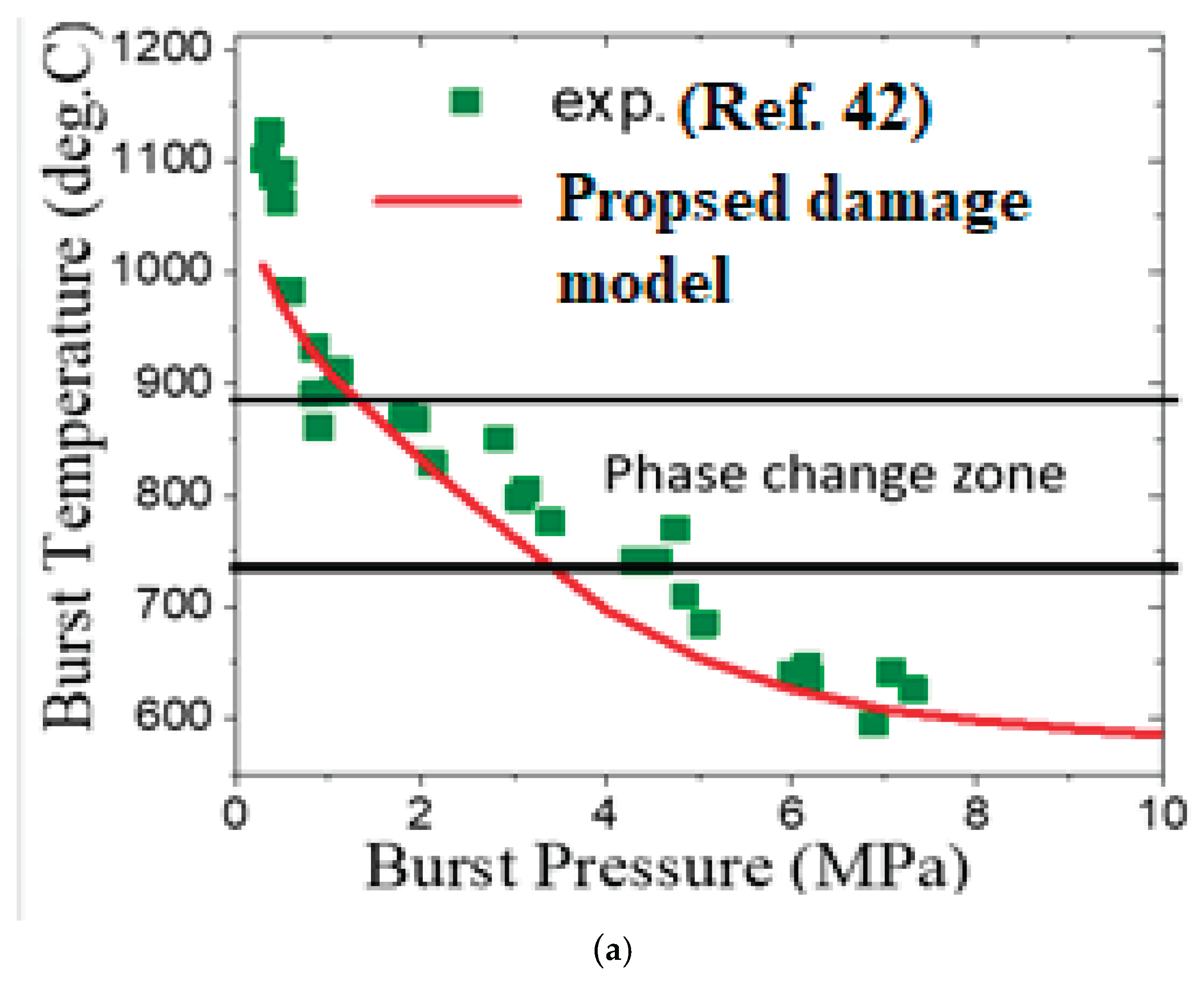
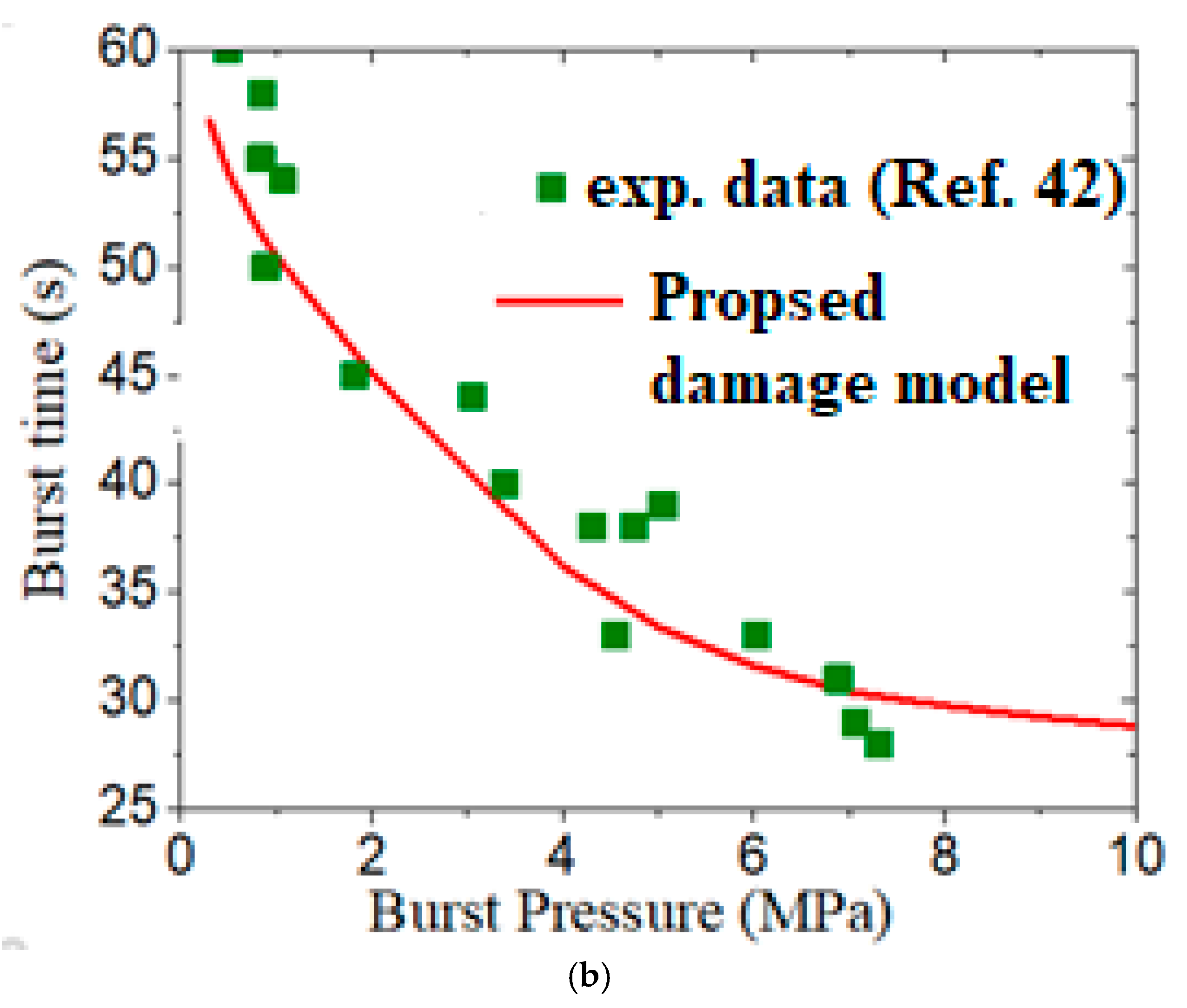
Figure 8.
Evolution of (a) von Mises stress and (b) equivalent creep strain at the maximum location of the clad with time for two different heating rates and internal pressure values; (c) Variation of burst temperature as a function of burst pressure for Zircaloy-4 fuel clad as predicted by the damage model.
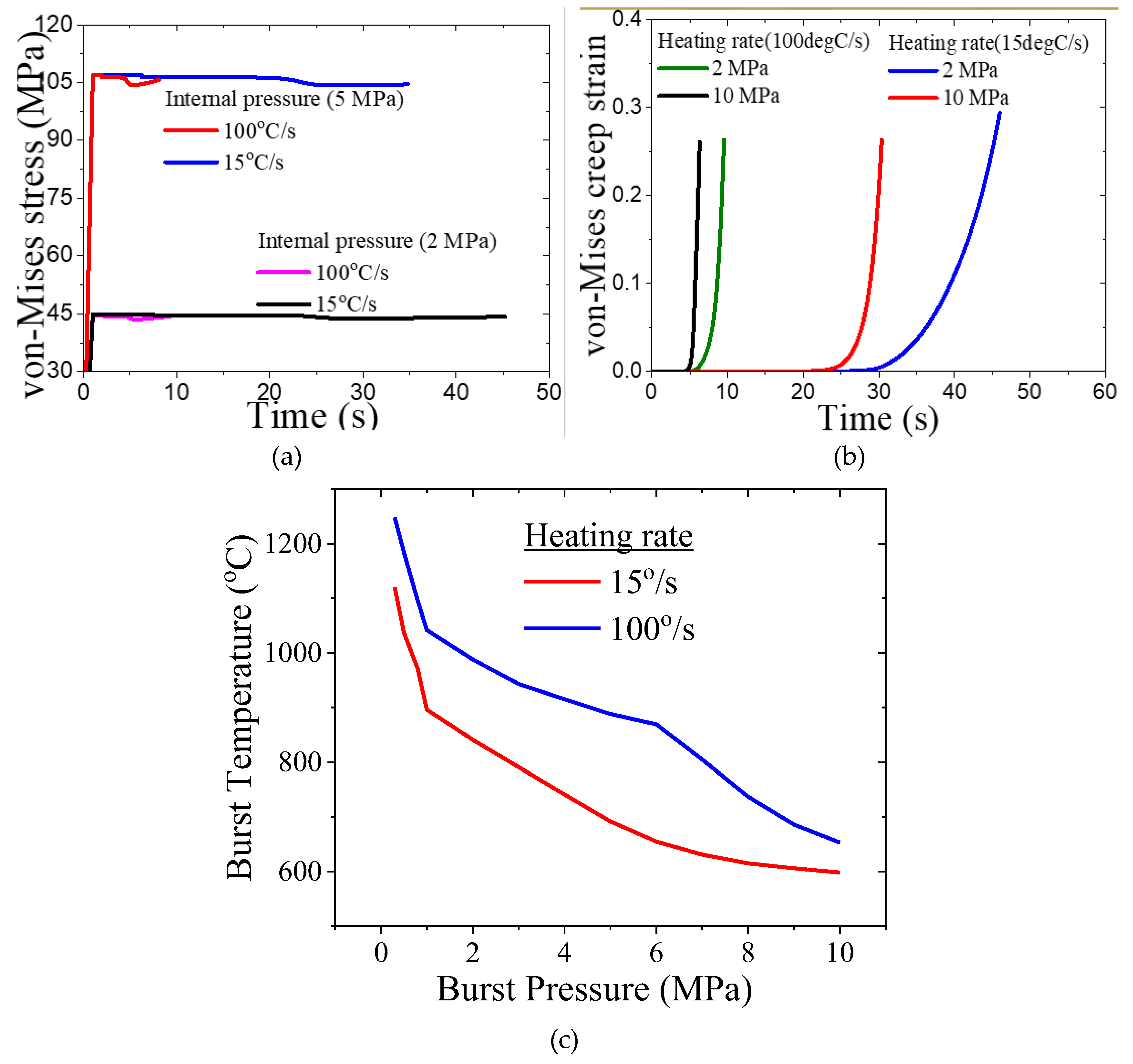
Figure 9.
(a) Burst stress as a function of burst pressure as obtained from experimental data taken from Ref. [42] along with the fitted exponential correlation; (b) Burst temperature vs burst pressure data as taken from Ref. [43] for two different heating rates.
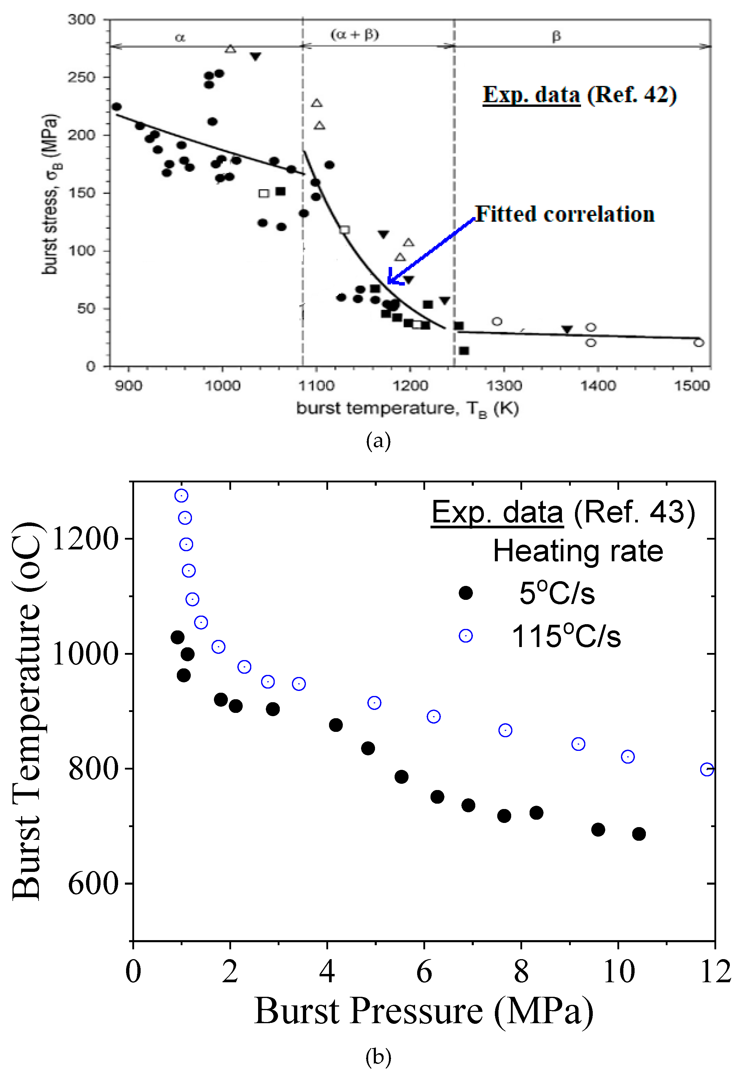
Figure 10.
Burst temperature vs initially applied stress as predicted by Rosinger [44] using an empirical model for various heating rates.
Figure 10.
Burst temperature vs initially applied stress as predicted by Rosinger [44] using an empirical model for various heating rates.
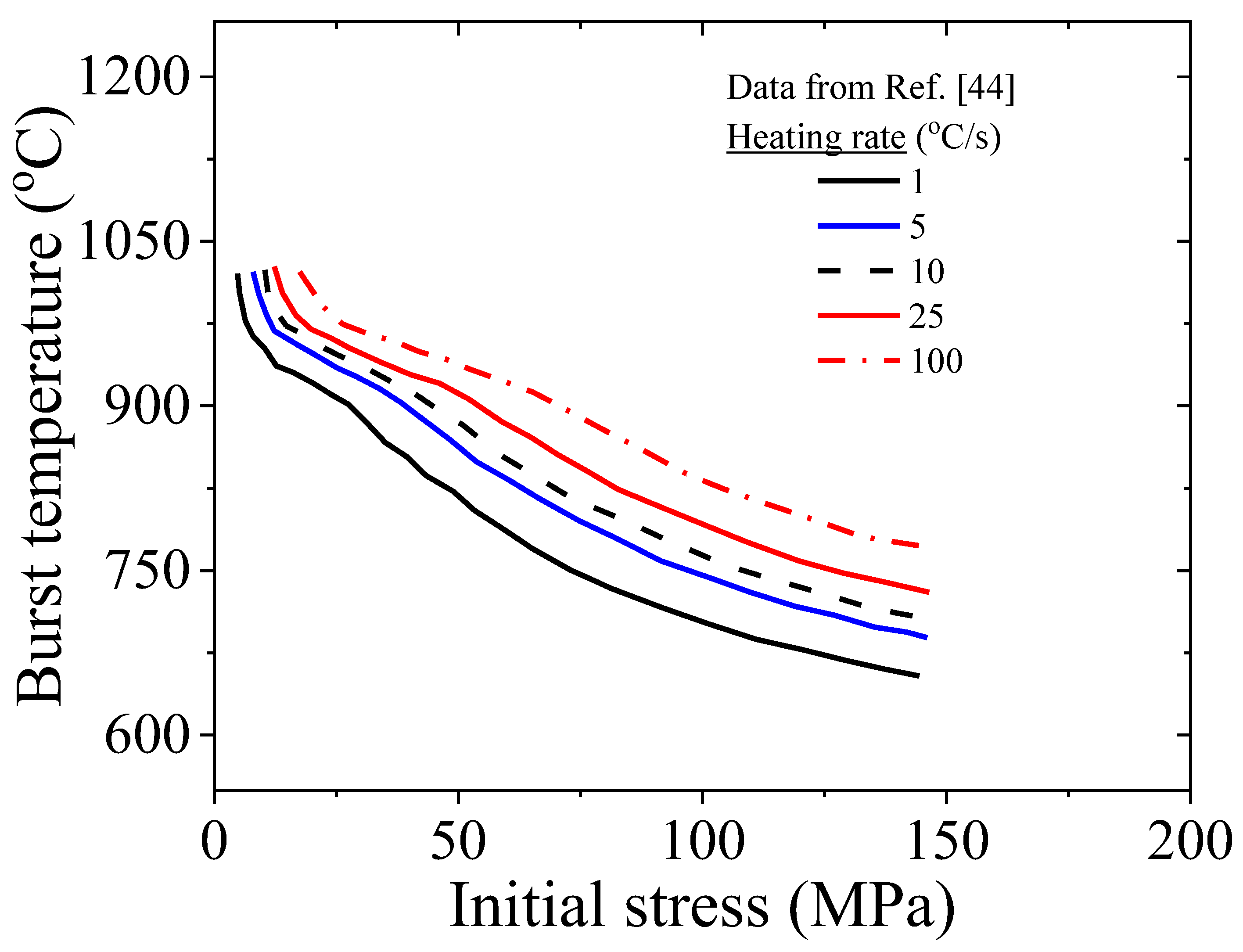
Figure 11.
Burst temperature vs initially applied stress as predicted by current damage model for various heating rates for Indian clad.
Figure 11.
Burst temperature vs initially applied stress as predicted by current damage model for various heating rates for Indian clad.
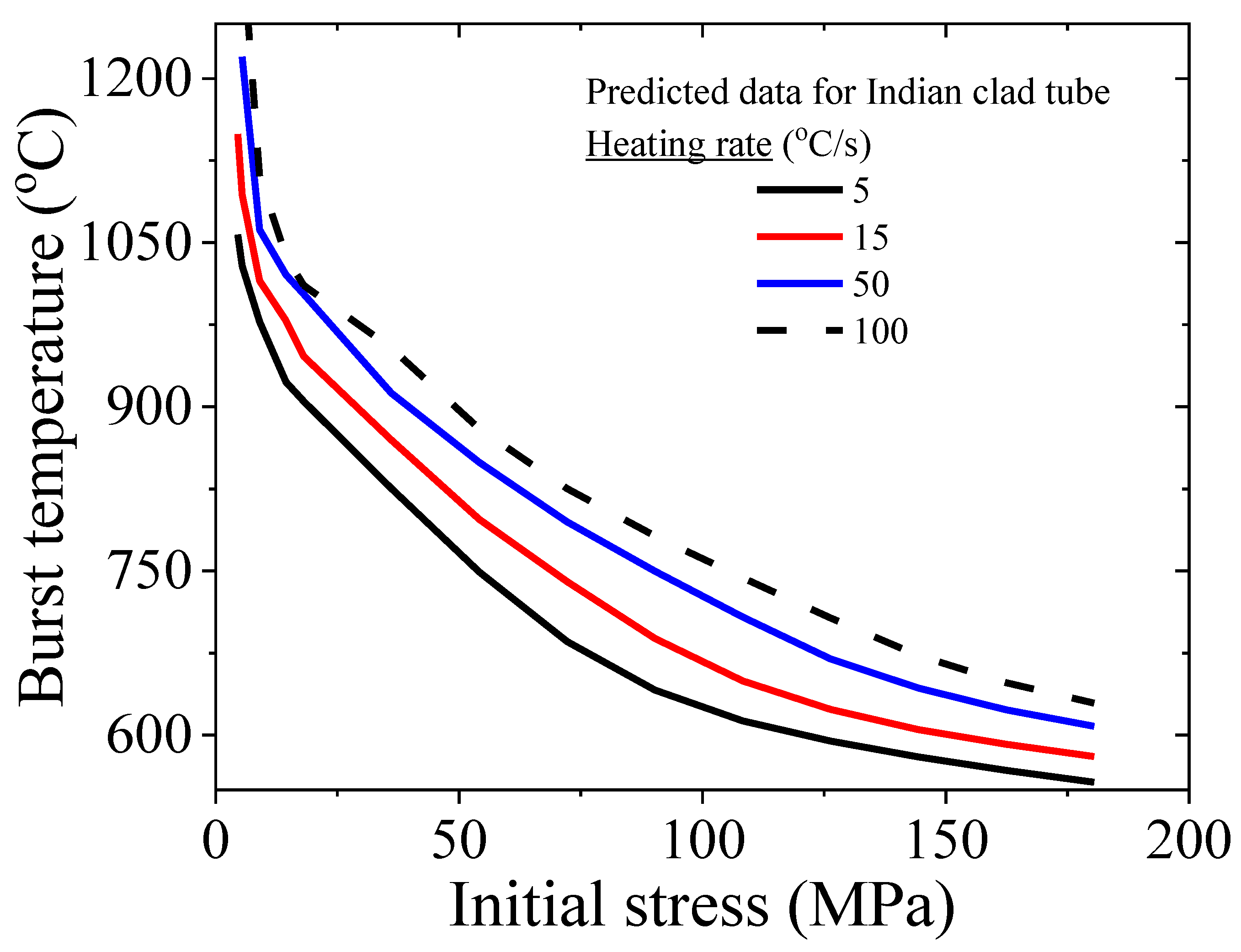
Figure 12.
(a) Variation of burst temperature with engineering burst stress for the reference heating rate of 5 °C/s and corresponding reference correlation for clad burst behavior; (b) Variation of normalized burst temperature with engineering burst stress for different heating rates varying from 5 °C/s to 100 °C/s; (c) Variation of normalized burst temperature with normalized heating rate and the corresponing proposed correlation.

Table 1.
Material parameters for modelling of creep deformation of Zircaloy-4 fuel clad in FE analysis.
Table 1.
Material parameters for modelling of creep deformation of Zircaloy-4 fuel clad in FE analysis.
| Temperature, T (°C) | n | C | A |
|---|---|---|---|
| (T<600) | 4.86 | 31620 | 1.2e4 |
| (600<T<650) | 4.68 | 31620 | 1.2e4 |
| (650<T<700) | 4.45 | 31620 | 1.2e4 |
| (700<T<750) | 4.35 | 31620 | 1.2e4 |
| (750<T<800) | 4.29 | 31620 | 1.2e4 |
| (800<T<850) | 4.25 | 31620 | 1.2e4 |
| (850<T<900) | 2.35 | 22600 | 9750 |
| (900<T<950) | 2.2 | 22600 | 9750 |
| (950<T<1000) | 2.11 | 22600 | 9750 |
| (1000<T<1050) | 3.45 | 16300 | 15 |
| (1050<T<1100) | 3.37 | 16300 | 15 |
| (1100<T<1150) | 3.31 | 16300 | 15 |
| (1150<T<1200) | 3.24 | 16300 | 15 |
Disclaimer/Publisher’s Note: The statements, opinions and data contained in all publications are solely those of the individual author(s) and contributor(s) and not of MDPI and/or the editor(s). MDPI and/or the editor(s) disclaim responsibility for any injury to people or property resulting from any ideas, methods, instructions or products referred to in the content. |
© 2025 by the authors. Licensee MDPI, Basel, Switzerland. This article is an open access article distributed under the terms and conditions of the Creative Commons Attribution (CC BY) license (http://creativecommons.org/licenses/by/4.0/).
Copyright: This open access article is published under a Creative Commons CC BY 4.0 license, which permit the free download, distribution, and reuse, provided that the author and preprint are cited in any reuse.


