Submitted:
23 June 2025
Posted:
24 June 2025
You are already at the latest version
Abstract
Direct detection systems are the mainstream choice for short-reach optical interconnects. As the data rate moving towards to 400G and beyond, conventional double-sideband intensity modulation and direct detection (IM/DD) systems lack inherent resistance to chromatic dispersion. The single sideband modulation was proposed to combat chromatic dispersion and extend the transmission reach. However, the penalty of single sideband modulation has not been analyzed. In this paper, we theoretically derive the SNR difference for both double sideband signal and single sideband signals in direct detection systems.
Keywords:
Optical communication
; direct detection
; single sideband modulation
1. Introduction
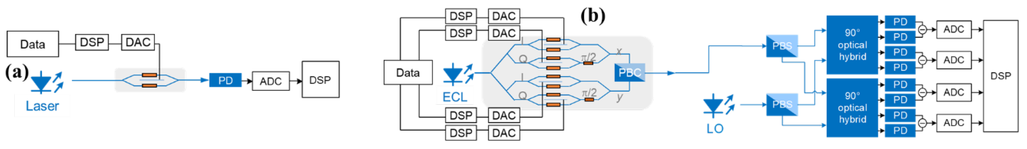
Direct detection (DD) is the dominant choice for short-reach optical interconnects due to its low cost and colorless operation, compared to the local oscillator laser enabled coherent detection [1]. As shown in Figure 1(a), only one photodiode (PD) and analog to digital converter (ADC) is required to recover the transmitted signal for direct detection. However, traditional intensity modulation and direct detection (IM/DD) systems [2,3] are highly susceptible to the power fading effect caused by chromatic dispersion (CD). Single sideband (SSB) modulation can be utilized to break the conjugate symmetry between the two sidebands of double-sideband signals [4,5], thereby overcoming the power fading effect. However, SSB modulation may underperform its double-sideband (DSB) counterpart in signal-to-noise ratio (SNR) performance due to the inherent filtering process involved.
In this work, we provide a theoretical SNR comparison between the DSB and SSB signals in direct detection systems. A 3-dB SNR advantage can be observed using DSB modulation.
2. Double Sideband Signal Reception
To avoid the CD-induced power fading effect, we assume that the DSB signal can be pre-compensated with an EO dispersion equalization transfer function , where is the time-domain transfer function of link CD. Then the transmitted optical field can be described as
Here is the optical carrier. is the DSB signal. and is the left and right sidebands, respectively. Conjugate symmetry of an IM signal is satisfied as . The notion stands for convolution.
After fiber link, the optical field at the receiver side can be obtained as
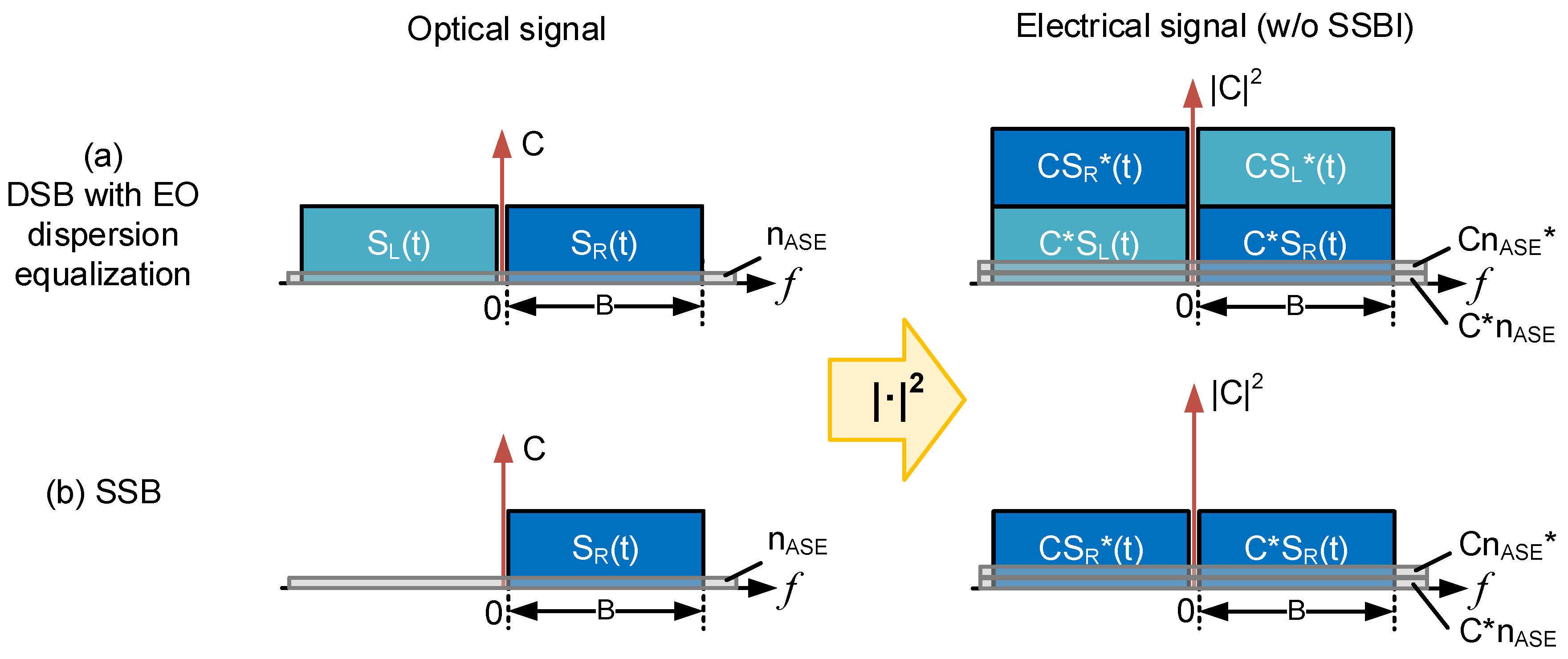
Here is the ASE noise. The optical and electrical spectra of the DSB signal are illustrated on the top of Figure 1.
After square-law detection of the PD, the photocurrent can be described as
Here we assume the responsivity of the PD is 1. The first term is the direct current (DC) term, and the last term is the signal-signal beating interference (SSBI). If the DC & SSBI terms are neglected, the photocurrent is
Based on the conjugate symmetry, we can only consider the positive frequency components only. Without loss of generality, we can assume to be real-valued and simplify the photocurrent to
Finally, the electrical SNR is calculated as
Here is the power of the right sideband of signal. is the noise power spectral density. is the power of the signal including carrier, which means for DSB signal. is the carrier-to-signal power ratio (CSPR).
3. Single Sideband Signal Reception
Without loss of generality, we assume the left sideband of the signal is filtered out while retaining the right sideband, yielding a single-sideband signal. It can be described as
The optical field at the receiver side is
Here The optical and electrical spectra of the SSB signal are illustrated on the bottom of Figure 1.
After the square-law detection at PD, the photocurrent can be described as
Here we assume the responsivity of the PD is 1. The first term is the DC term, and the last term is the SSBI. If the DC and SSBI terms are neglected, the photocurrent is
Here we only consider the positive frequency component.
Now we can calculate the electrical SNR of the SSB signal as
Figure 2.
The optical and electrical signal spectra illustration of (a) DSB and (b) SSB signals.
Here is the power of the signal including carrier, which means for SSB signal.
4. Conclusion
According to the calculated electrical SNR [eq. (6) and eq. (11)], we can find that the SNR is reduced to a half when SSB modulation is employed compared to DSB signal given the same CSPR. In other words, if we use DSB modulation instead of SSB, 3-dB SNR advantages can be achieved. Therefore, to meet the current stringent SNR and receiver sensitivity requirement, to compensate the dispersion in double sideband systems is more favorable than single side band systems.
Acknowledgements
This work is supported by National Key R&D Program of China (2024YFE0105600) and National Natural Science Foundation of China (62271010, U21A20454, 62475147).
References
- K. Kikuchi, “Fundamentals of Coherent Optical Fiber Communications,” in Journal of Lightwave Technology, vol. 34, no. 1, pp. 157-179, 2016. [CrossRef]
- D. Che and X. Chen, “Higher-Order Modulation vs Faster-Than-Nyquist PAM-4 for Datacenter IM-DD Optics: An AIR Comparison Under Practical Bandwidth Limits,” in Journal of Lightwave Technology, vol. 40, no. 10, pp. 3347-3357, 2022.
- O. Ozolins, A. Ostrovskis, T. Salgals, et al., “Optical Amplification-Free 310/256 Gbaud OOK, 197/145 Gbaud PAM4, and 160/116 Gbaud PAM6 EML/DML-based Data Center Links,” in Optical Fiber Communication Conference (OFC) 2023, Technical Digest Series (Optica Publishing Group, 2023), paper Th4B.2. [CrossRef]
- Benedikt Baeuerle, Claudia Hoessbacher, Wolfgang Heni, et al., “100 GBd IM/DD transmission over 14 km SMF in the C-band enabled by a plasmonic SSB MZM,” Opt. Express 28, 8601-8608, 2020. [CrossRef]
- C. Wang, et al., “Beyond 200 Gbit/s/λ VSB PS-PAM8 Employing Joint Neural Network Equalization at C-band,” in IEEE Photonics Technology Letters, vol. 34, no. 18, pp. 941-944, 15 Sept.15, 2022. [CrossRef]
Figure 1.
The structure of (a) IM/DD systems and (b) coherent detection systems. DSP: digital signal processing. DAC: digital to analog converter. PD: photodiode. ADC: analog to digital converter. PBC: polarization beam combiner. PBS: polarization beam splitter. LO: local oscillator.
Figure 1.
The structure of (a) IM/DD systems and (b) coherent detection systems. DSP: digital signal processing. DAC: digital to analog converter. PD: photodiode. ADC: analog to digital converter. PBC: polarization beam combiner. PBS: polarization beam splitter. LO: local oscillator.
Disclaimer/Publisher’s Note: The statements, opinions and data contained in all publications are solely those of the individual author(s) and contributor(s) and not of MDPI and/or the editor(s). MDPI and/or the editor(s) disclaim responsibility for any injury to people or property resulting from any ideas, methods, instructions or products referred to in the content. |
© 2025 by the authors. Licensee MDPI, Basel, Switzerland. This article is an open access article distributed under the terms and conditions of the Creative Commons Attribution (CC BY) license (http://creativecommons.org/licenses/by/4.0/).
Copyright: This open access article is published under a Creative Commons CC BY 4.0 license, which permit the free download, distribution, and reuse, provided that the author and preprint are cited in any reuse.


