Submitted:
11 June 2025
Posted:
12 June 2025
You are already at the latest version
Abstract
Traditional approaches in tunnel lighting have been directed towards the installation of appropriate luminaires in the intermediate and transitional sections with the simple objective of diminishing the effect of delayed visual accommodation during daylight hours. Such efforts run in parallel with the target of keeping the electrical use at the lowest level. Nevertheless, inadequate attention has been conceded to the interior areas, whose noticeable longitude in several instances and subsequently the duration of occupancy of the users, can produce discomfort in the majority of the tunnel or underground passageway. It is in this region, where the flicker effect presents a more remarkable impact. Although such effect is in fact uncomfortable, the strategies to eliminate it efficiently have not been developed in depth and the result is still deserving. The reasons for this neglect as well as some particularities and solutions are exposed and discussed in the present article. Specifically, it is demonstrated that the use of sunlight can be an adequate initiative to design and retrofit tunnels capable of hampering or totally avoiding the unwanted effect. The innovative tunnel geometry explained in this manuscript is not cylindrical and also it is not based in revolution forms. Thus, it prevents the appearance of such unnerving visual effects which also endanger security. We are in the position to prove how the vector field generated by the normal to the points of the novel surface displayed, remains non-parallel, ensuring appropriate diffusivity. In the same manner, the notion of tunnel is extended from a linear system to a veritable network of galleries which can traverse in space bi or even three-dimensionally. Accordingly, we will offer diverse instances of junctions and splices which further enhance the capabilities and improvements of this disruptive technology.
Keywords:
Innovative Geometry for Mechanics. Energy Savings
; Sunlight radiation
; Tunnel Lighting
; Flicker Effect
1. Introduction
The lighting of road tunnels is a complex task due to its critical impact on drivers and safety [1,2,3,4] as well as its high consumption in economical, energy and financial resources. This fact is becoming more and more important in the last years due to the exponential increase of tunnels, especially the very long ones. As consequence of the high amounts of energy and raw materials required as well as the manufacturing processes, the environmental impact of these installations is also high in emissions and other kinds of waste.
The explanation to the abovementioned impacts lies on physical, physiological, and psychological peculiarities of people. The consequence is that accurate visual perception, good performance and short visual reaction time (VRT) must be ensured through very high luminance levels, especially during daytime because, otherwise, the slow visual adaptation when going from bright to darker environments (Figure 1), may cause disturbing effects making driving even more dangerous [5]. Furthermore, the visual adaptation is not an isolated problem because drivers in tunnels and long underground roads, also experience physiological and psychological impairments due to their singular characteristics [6,7,8,9,10,11].
In addition, the high luminance levels required to mitigate the abovementioned disturbing effects are a problem themselves because of the consequent consumption of energy, number of projectors, wiring and maintenance. All this means a worrying economic and environmental impact. This is the reason why research on strategies to make tunnel lighting more sustainable through the decrease in the consumption of energy and installed projectors, has experienced a big boost in the last years. The proposals up to date go from the decrease in the luminance requirements through interventions in the portal surroundings [12] to strategies to introduce the light of the sun inside the tunnel with or without displacement of the infrastructure [13,14].
In summary, it is necessary to ensure the minimum luminance necessary to achieve visual adaptation and avoid some related disturbing effects that take place during daytime, whilst progressively carrying out a luminance decrease as the eye gets adapted in order to save energy, installed projectors and environmental impact.
To implement this decrease, road tunnels are divided into five different sections with different performances of their respective lighting installations. The zones have different lengths and requirements in terms of illuminance from the floor and vertical surfaces. These zones are the following [5]:
- Access zone: section of the opencast road immediately before the portal gate with a length of the stop distance (SD). The luminance on the driver eye in this zone (L20) determines his visual adaptation to the darker environment of the tunnel and, hence, the luminance requirements from pavement and walls are much higher than in the following parts inside the tunnel
- Threshold zone: first region of the tunnel with a length of the braking distance. With the target of ensuring a smooth transition and accurate visual adaptation, this zone presents the highest required luminance (Lth) and hence, it is the most consuming one in terms of energy and projector. In spite of its high magnitude, the luminance in this zone starts to progressively decay from is second half.
- Transition zone: section of the tunnel immediately after the threshold region whose length is the one covered by a vehicle at the maximum allowed speed inside the tunnel during 20 s. Its luminance requirements (Ltr) are lower than in the preceding threshold zone. The luminance in this zone continues decreasing for the sake of energy savings.
- Interior zone: it is the zone after the transition one and just before the exit zone. Its photometric requirements are the lowest because the driver is supposed to attain a reasonable visual accommodation. The levels are uniform along the whole area and, depending on the type of tunnel and the traffic, they can vary between Lin = 1 – 10 cd/m2.
- Exit zone: this zone starts immediately after the interior zone at SD and finishes at the end of the tunnel. The required luminance, Lex, raises from Lin up to 5 Lin up to 20m before the exit gate, where the visual environment is dominated by the exterior conditions.
According to this division, the interior zone requires the minimum consumption in energy and installed projectors in the whole tunnel. Although this circumstance is positive, there are also important cons: the long separation between projectors, produces inhomogeneous distribution of luminance on the road and walls. The reason is that tunnels have a maximum height, and the light cones rarely overlap in the interior zone.
The parameter taking into account the distribution of the luminous flux on the pavement and walls, is the global luminance uniformity (U0). It represents the uniformity of the visual field perceived by the users, and is defined by CIE International Standard S 017/E:2015 [15] as:
where Lmin and Lav are the minimum and average luminance levels on the pavement.
U0 > 0.4 is required by several norms to grant the uniformity of the visual field.
When the global luminance homogeneity is scarce due to an inhomogeneous distribution of the luminous flux on the vertical surfaces and floors, the drivers can experience one disturbing effect, the so called “flicker effect”, which is the target of this work.
2. The Flicker Effect
Besides the problem of visual accommodation, lighting facilities in tunnels and underground passageways must dampen, among other disturbing circumstances, the “Flicker effect”, which is the succession of bright and dark bands on the pavement and walls as shown in Figure 2 [5,16,17]. When the succession has some concrete frequencies and duration, it can produce lack of concentration, headache or dizziness, and can be a serious danger for drivers. This effect is frequent in the interior zone of road tunnels and the so called Very Long Underground Roads (VLUR).
The frequency of appearance of the said stripes has a frequency offered by equation (2) [5]:
where vmax represents the maximum velocity allowed in the tunnel of underground zone, and I, is the spacing between the centers of the projectors in the zone of the tunnel under consideration.
According to CIE Publication 88:2004 [5], the effect is negligible at frequencies lower than 2.5 Hz and higher than 15 Hz. However, when the frequencies lie in the interval 4 to 11 Hz and the exposure of the succession is longer than 20 seconds, it is recommended to carry out the relevant actions to change the frequencies because the effect can appear.
Although this interval is well established, it is necessary to highlight that measuring the distance I between projectors from center to center as per equation (2), may be too conservative in terms of the calculated frequencies, because it assumes that the light cones have no aperture. According to (2), the flux is strictly confined to a trough directly under the center of the projector. In other words, the formula to calculate the flicker provided by most regulations makes it unviable any kind of overlap of the light cones even if it actually exists.
Anyhow, the reason behind this effect is precisely the lower luminance demands in the interior zone. Due to the increasing cost and relatively low variety of projector models during years, the installations in interior zones had high spacing between projectors. The combination of such large distancing with the limited height of the tunnel vault, does not allow the overlap of the light cones and consequently, a succession of bright and dark stripes appears on the walls and, mainly on the road surface [16].
The classical action to avoid the flicker effect has been the installation of projectors with light cones wide enough or using more projectors of lower power to decrease the distance between them. This last increases the price of the installation and its maintenance.
In the next section, some of the ideas proposed up to date are presented.
3. Methods and Proposals to Avoid the Flicker Effect in Tunnels and Very Long Underground Roads (VLUR)
Once we assume the drawbacks to achieve a proper overlap of the light cones in the interior zone, it is necessary to think of tactics to improve luminance uniformity and thus, avoid the flicker effect.
The classical solution has consisted on the use of more projectors with lower power in the interior zone, instead of fewer of high luminous flux. In this way, there is a chance to overlap the cones. However, one installation with more projectors is more expensive in terms of initial investments, use of raw materials for wiring and other devices, maintenance and recycle at the end-of-life cycle of both, projectors, and lamps.
For this reason, other proposals are needed. Some works have proposed ideas from different perspectives [10], but the continuous development of tunnel lighting has made it possible to introduce new products and strategies that, although initially designed for other purposes, can contribute to eliminate the flicker effect in the threshold zone:
1) Decrease of the luminance required inside the tunnel through interventions in the portal surroundings like forestation or introduction of scaled surfaces to reflect the sunlight out of the L20 cone from the approaching drivers’ eyes. This decrease results in less emitted flux and lower contrasts between light cones and darker areas, contributing to the elimination of flicker effect.
2) Installation of continuous stripes of LED along the whole tunnel or underground road as shown in Figure 3. These stripes can be installed at least in the interior zone where the flicker effect is much more likely to happen. Although the intensity emitted by these relatively new products is much lower than the one emitted by classical High Pressure Sodium projectors, the luminance on the road can be enough to fulfill the requirements in this zone and even in the level of nighttime.
3) Addition of sunlight to the electrical lighting. Although most strategies using sunlight in road tunnels are designed to achieve a good visual adaptation when entering the threshold zone, some of them could be useful in the interior zone to achieve better uniformity.
Among the two kinds of strategies to use the light of the sun in tunnels, the first one consists of partially shifting the threshold zone out of the tunnel [19,20,21,22,23,24,25,26,27,28,29,30]. It is evident that this strategy cannot be applied to the interior zone and is not useful to mitigate the flicker effect because, due to the short separation between projectors in this zone, the effect is not likely to happen there.
On the other hand, a second kind of strategies is based on the injection of sunlight inside the tunnel through light-pipes with or without heliostats [31,32,33] or through fiber-optics [34,35].
The selection of one or another way to save energy through the use of sunlight depends on many factors and is complex. Some tools recently developed like the so called SLT equation [36] have the capability to predict which kind of strategy can be better in each tunnel for given target energy savings.
Anyhow, the potential use of sunlight to fight flicker effect has to reside in the second kind of strategies, that is, the injection of solar flux inside the tunnel to reach the interior region as long as it is homogeneously distributed on the walls and road surface. In this sense, the injection system recently presented by Peña-García and Cabeza-Laínez [32]. It consists on a coupled system “outer light collectors-ground based light-pipes – distributing vault” as shown in Figure 4.
This system improves the lacks and limitations of other proposals thanks to two ground-breaking factors:
- The lower chamber of the light-pipes on the ground and shoulders of the road
- The introduction of a complex-shaped vault capable to reflect and distribute the solar flux transported by the light-pipes uniformly on the pavement.
To find the internal distribution of solar radiation inside the complex geometry that we are proposing we need to clarify briefly the underlying logic of the novel simulation system that we are proposing. It is mainly based on the reciprocity theorem of radiation.
Since it was enunciated on several occasions from the 18th century [33], we will begin with the fundamental expression that describes the emission and reception of radiative energy between two or more non-black bodies of any spatial form and independently of the position adopted by them as represented in Figure 5. The law features directional cosines, distances and areas under the form below (Equation (3)):
Equation (3) is often termed the reciprocity theorem. It quantifies the probability of radiative energy by unit area to impinge on any of the two surfaces concerned, that is, E1 and E2. The respective angles of incidence θ1 and θ2 which are drawn from the figure represent the inclination to the normal of the distance line that unites two points which belong to each surface called r12, in the equation as in the figure [34].
In order to solve Equation (3), which allows for evaluation of the amount of a so-called form factor that involves the two sources, we need to work out four rows of integration, as explicated in Equation (4) [34].
Nevertheless, since the new shapes proposed are so complex we would concentrate on the first and second steps (Equation (5)), which are more affordable, leaving a sort of herald for the next step which takes the form of a constant (x0) and then turns into a variable in the subsequent phases [35]; that is, it becomes active for the last two phases of integration.
We would then use for the last two operations a numerical method that extends the former findings to the surface of emission as a sort of median value. In this way, we attain the desired figure of the form factor attributed to the two surface sources concerned with considerable accuracy [36]. Afterwards, we show how to apply the so-obtained form factors for semicircular apertures at the beginning of the tunnel [37,38].
For the inclined parts of the vaults we will employ the expressions below and detailed in Appendix A.
Other methods to address the preliminary integrals have been presented but they are often inaccurate.
In order to develop our method, we start for simplicity with a semicircle of radius a, placed at the intersection of the main axes X, Y and Z (Figure 6).
Under this disposition, the coordinate Z axis is vertical and X is horizontal and perpendicular; the Y axis is perpendicular to the semicircle; and the radius of the circular sector turns, in Z, equal to rsinα, and in X, to rcosα as in Figure 6.
The new geometry developed for the tunnel is not cylindrical and therefore it does not concentrate the annoying stripes of light and shade since the curvature of the tunnel varies at each section as shown in Figure 7.
The basic expression that can be employed for the typology of ruled shapes follows the norm (Eq.6),
With the affected parameters represented in Figure 6 above.
It can be shown that in order to produce the normal to the surface in terms of F(x,y,z) a first rank differentiation is duly required. Then, the perpendicular vector is found as N = (Fx, Fy, Fz) and in this case, the operation yields (Eq.7):
Subsequently, we are able to generate a vector array composed of the previous mentioned normals whose main feature, as deducted from Eq.7, is the scattering of luminous energy in such a fashion that the undesired flicker effect remains positively prevented.
However, in order to develop this complex problem of luminous radiative transfer we need to identify the emission due to inclined surfaces by dividing the arches formed in the tunnels into small segments.
A general inclined surface used in the vaults (Figure 8) induces the radiative transfer presented in the following equation (Eq. 8),
After a lengthy integration (see Appendix A), we obtain the results in Eq.9,
For a general position of the point on the XY plane we find (Eq. 10),
Adding the effect of different stripes for the whole length of the tunnel, we can obtain several nephographs with the results of light diffusion due to the proposed non-revolution geometry.
Particularly, Figure 9 describes the simulation, that gives a uniformity ratio U0 = 0.73, brighter than the minimum required by international norms.
In summary, the lack of superposition of the cones in the interior region can be effectively achieved thanks on the one hand to the surplus of sunlight with a deft new system which ensures a homogeneous distribution on the pavement level, and on the other hand to the benefits offered by the innovative geometry that we have worked out in the previous stages of this research [38,39].
The innovative set is not only conceived to induce linear connections between two points [40] but an actual three-dimensional array of passageways in all possible directions that can be used for very different purposes left alone transportation, like mining facilities, bunkers, sewage or even storage of stocks and supplies among others. [40,41].
Several examples of square, triangular and inclined intersections are depicted in Figure 10, Figure 11, Figure 12, Figure 13, Figure 14, Figure 15 and Figure 16.
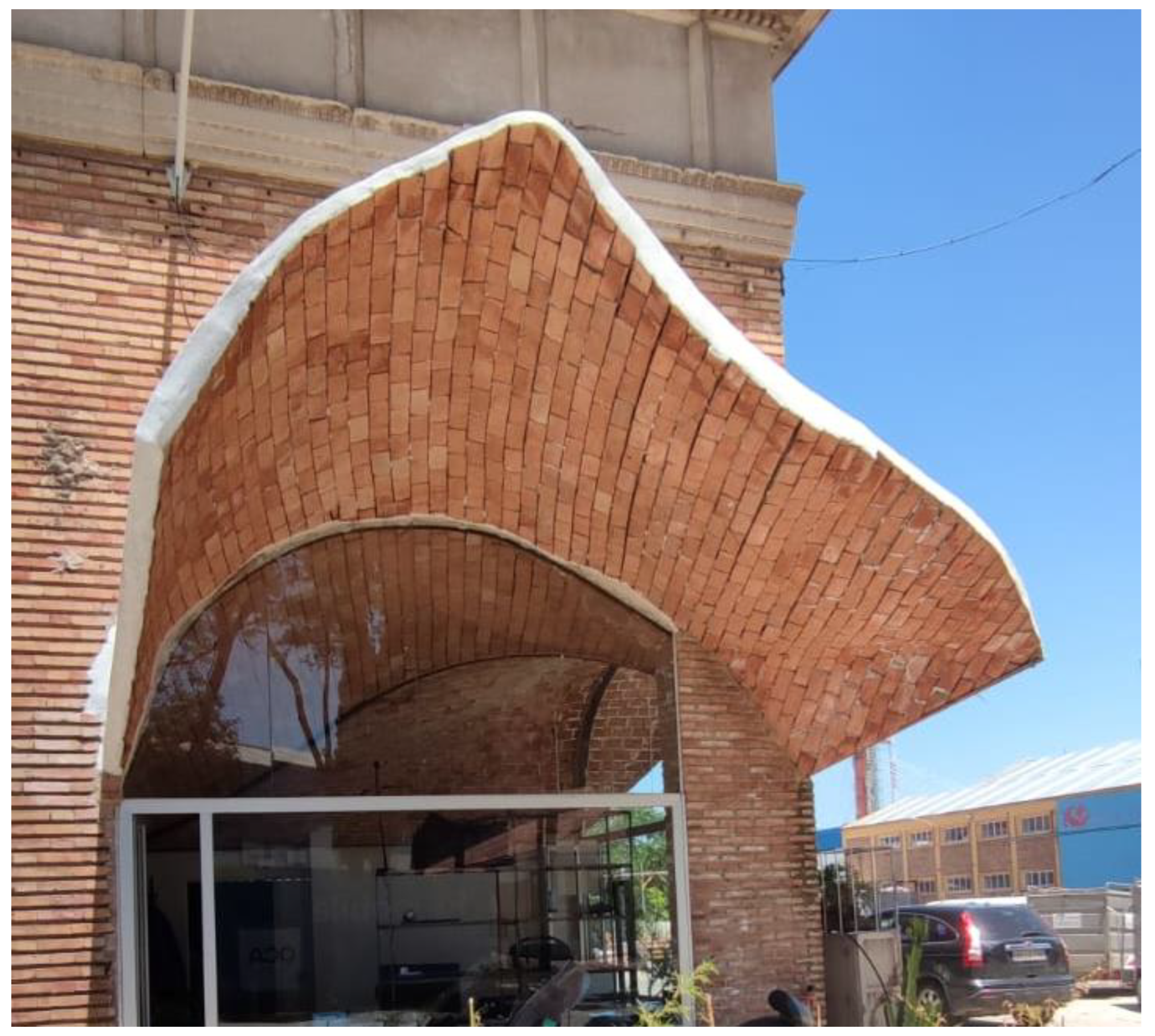
A life-size model of the intersection has been constructed at the construction research laboratories of the University of Seville (Figure 17 and Figure 18). We are subsequently proceeding to monitor the different parameters required such as mechanical resistance, lighting reflectivity and temperature build-up of the material. The construction costs of this novel geometry made in reinforced ceramic brick do not exceed 200 EUR per square meter.
4. Discussion
The considerable augment in the number, dimension, and complexity of tunnels during recent years is surpassing all reasonable expectations. It implies a surge of the pending problems associated to illuminating such underground structures, that most often develop based on the conventional pair safety-consumption. The strict visual requirements under such dangerous conditions, and the singular perception stimuli that occur in the regions within, especially during daylight hours where users arrive to the tunnel immediately after a glare environment, must be accounted for [42,43]. For this reason, the luminous levels should be sufficiently bright to guarantee an appropriate visual accommodation for the daytime but this should not be the sole factor to be considered in the design of infrastructures. Nonetheless, this high power lighting often carries with it a huge energy use, excessive or redundant fixtures, as well as electrical devices and maintenance. Besides its environmental impact is unaffordable due to wasteful emissions and other associated disadvantages.
Moreover, when project-managers and public offices try to counterpoint the aforementioned binomial of safety and sustainability, an added vector emerges: the impairing flicker effect. It can be described as the succession of gloom and bright areas in close proximity which tend to affect the adaptability of light cones in the eye globe. When this effect appears in a given segment of frequency and time, it may cause noticeable nuisance and endanger the vehicles circulating in the passageway.
The flicker effect may occur at any moment, but it will appear more likely in the interior area as a consequence of its less demanding luminous requirements that permit a longer distance between fixtures. The obnoxious phenomenon is particularly linked to cuboid or cylindrical shapes and in that sense we have contributed with non- revolution or non-axial geometries that although more difficult to build ensure avoidance of the said effects.
The accurate computation of the distribution of the luminous challenge inside these kind of novel geometries is a challenge that we have been able to overcome with time and with the help of the radiation postulates of Cabeza-Lainez.
Albeit the international norms on tunnel illuminance take into account flicker effect, there is today a sort of compromise that accepts it as an inevitable side-effect of underground circulation facilities.
In this manuscript, the combination of counter-measures in the vicinity of the portal entrances to diminish the luminance requirements for the interior of the tunnels, joined to the introduction of Ld stripes and sunlight conduits which issue towards an especially reflective vault, created by means or ruled surfaces that originate in the semicircle, induces a uniform light distribution on the road plane that completely averts the flicker effect associated with the luminaires as we have demonstrated in the results.
In addition, we have contributed with adroit developments of the said innovative geometry honed by means of computational procedures which appear very adequate to diminish energy use and augment the security and well-being of complete areas of network connections intended for circulation or other urban and industrial purposes [44].
Thus, the necessity of installing the proposed systems answers to a twofold requirement: the imperative of energy conservation for a high-demanding threshold area of the passageway and, as outlined in the manuscript, the avoidance of the ever-present flicker effect manifest within the darker zones of the facility, which can in be completely dampened in this manner through a more natural and elegant fashion, altering the conventional system of design through a different kind of mathematical formulation.
For future research, we would intend to generalize the novel concepts and instruments described, in the belief that surely they will lead to a new understanding of the shapes and manners in which underground transportation has been thus far conceived and implemented.
Author Contributions
All authors have contributed accordingly to this manuscript and have read and agreed to the published version of the manuscript.
Funding
This research received no external funding.
Institutional Review Board Statement
Not applicable.
Informed Consent Statement
Not applicable.
Data Availability Statement
Not applicable.
Conflicts of Interest
The authors declare no conflicts of interest.
Appendix A
Let us develop the process by which we can obtain the lighting distribution field due to a complex inclined geometry.
In a canoniccal development from the previously described formulas [32]
We need to change the z axis to take into account the inclined line in which the study point lies, to z1.
z1 goes from a-Dcosφ at the upper extreme corresponding to z=a, to -Dcosφ if z=0. Therefore z1=z- Dcosφ.
Subsequently we need to identify r and cosθ. As y is a constant and equals Dsinφ,
Cosθ2 refers to the normal to the direction of the study point which resides on the vector (0, Dsinφ, -Dcosφ) and by simple derivation this normal, perpendicular to the point containing the point, is defined by the vector (0, Dcosφ, Dsinφ). [33]
The scalar product of the normal and the arbitrary vector on the surface of the rectangle gives us the value of the searched cosine,
Therefore,
The complete integral will give,
Remembering that,
The configuration factor f, on the given point with angle φ can be divided into the sum of two integrals with the limits of b and 0 for x and the established ones for z1.
Let us first consider the second part of the integral,
With respect to z1 it is easy to find that we have just the derivate of the quotient of the expression in the denominator,
The expression turns out to be,
These two integrals are of the arc of tangent type,
With which the former integral is transformed into,
The final result of this part will be,
Multiplying by D which was outside of the integral, we arrive to,
Let us proceed with the other integral,
First we extract the constants,
We can subsequently integrate with respect to x,
This expression is of the type:
where X= x2+ k2 and Y=arctgx/k
In this case k= (A19)
Therefore, the integral gives,
Substituting we obtain,
Now, we need to integrate this with respect to z1,
Leaving out ½, the first part can be transformed into a subtraction of quotients,
For now, we can call the first quotient A and the second one B, and thus the integral yields,
We can continue now with the second term containing the arc of tangent. This type of integral is usually solved by parts.
By making
We known that,
Integrating with respect to z we arrive to,
By substituting the limits of the first term, we receive,
Outside of the integral we had left,
Multiplying we obtain,
Grouping,
Which, remembering the formerly found results and adding them, produces,
And this will provide us with,
And the other fragment of the solution by parts simplifies to,
With the development of the method by parts, we will receive in the first part of the former method,
And the other fragment of the solution by parts simplifies to,
For a general position of the point on the XY plane we find,
References
- Amundsen, F.H.; Ranes, G. Studies on traffic accidents in Norwegian road tunnels. Tunn. Undergr. Space Technol. 2000, 15, 3–11. [Google Scholar] [CrossRef]
- Caliendo, C.; De Guglielmo, M.L. Accident Rates in Road Tunnels and Social Cost Evaluation. Procedia - Social and Behavioral Sciences 2012, 53, 166–177. [Google Scholar] [CrossRef]
- Danishmal, M.; Zainullah, S. Investigating the Importance of Tunnel Lighting and its Role in Reducing Traffic Accidents. Academic Journal of Research and Scientific Publishing 2021, 3, 39–57. [Google Scholar] [CrossRef]
- Li, Z.; Xing, G.; Zhao, X.; Li, H. Impact of the connected vehicle environment on tunnel entrance zone. Accident Analysis & Prevention 2021, 157, 106145. [Google Scholar]
- Commission Internationale de l’Éclairage (CIE). Guide for the lighting of road tunnels and underpasses, CIE Publ. 88, Vienna, 2004.
- Peña-García, A.; Gil-Martín, L.M.; Espín-Estrella, A.; Aznar-Dols, F. Energy saving in road tunnels by means of transparent tension structures. In: International Conference on Renewable Energies and Power Quality (ICREPQ’10). Granada (Spain), 2010.
- Larue, G.S.; Rakotonirainy, A.; Pettitt, A.N. Driving performance impairments due to hypovigilance on monotonous roads. Accident Analysis & Prevention 2011, 43, 2037–2046. [Google Scholar]
- Qin, X.C.; Zhang, N.; Zhang, W.H.; Meitner, M. How does tunnel interior color environment influence driving behavior? Quantitative analysis and assessment experiment. Tunn. Undergr. Space Technol. 2020, 98, 10. [Google Scholar]
- Miller, E.E.; Boyle, L.N. Driver behavior in road tunnels association with driver stress and performance. Transportation Research Record 2015, 2518, 60–67. [Google Scholar] [CrossRef]
- Flø, M.; Jenssen, G.D. Drivers’ perception of long tunnels. Studies from the Quinling Shongnan Tunnel in China as well as the Lærdal tunnel and the World longest subsea tunnel (Rogfast) in Norway. In: 4th International Conference-Traffic and Safety in Road Tunnels, 25–27 April 2007.
- Chen, P.; Chen, F.; Zhang, L.; Ma, X.; Pan, X. Examining the influence of decorated sidewaall in road tunnels using fMRI technology. Tunnelling and Underground Space Technology 2020, 99, 103362. [Google Scholar] [CrossRef]
- Peña-García, A. Scaled hillsides to decrease the energy consumption of lighting installations in road tunnels. Tunnelling and Underground Space Technology 2024, 148, 105779. [Google Scholar] [CrossRef]
- Peña-García, A. Sustainable tunnel lighting: One decade of proposals, advances and open points. Tunnelling and Underground Space Technology 2022, 119, 104227. [Google Scholar] [CrossRef]
- Peña-García, A. Strategies to decrease energy consumption in tunnel lighting: the feasible compromise between Safety and Sustainability. 2021 Joint Conference - 11th International Conference on Energy Efficiency in Domestic Appliances and Lighting & 17th International Symposium on the Science and Technology of Lighting (EEDAL/LS:17), 2022, 1-4.
- Commission Internationale de l’Éclairage, CIE, 2011. ILV: International Lighting Vocabulary, CIE Publ. S017/E:2015, Vienna.
- Peña-García, A. The impact of lighting on drivers well-being and safety in very long underground roads: new challenges for new infrastructures. Tunnelling and Underground Space Technology 2018, 80, 38–43. [Google Scholar] [CrossRef]
- Iacomussi, P.; Radis, M.; Rossi, G. Flicker effects in tunnel lighting. Proceedings of CIE 2017 Midterm Meetings and Conference on Smarter Lighting for Better Life, 641-648, 2018.
- Peña-García, A.; Cabeza-Laínez, I. The control of flicker effect as pivotal element for the luminance of Transport Tunnels and Continuous Transportation Infrastructures (VLUR). 2023 IEEE Sustainable Smart Lighting World Conference & Expo (LS18), Mumbai, India, 2023, pp. 1-5.
- Gil-Martín, L.M.; Peña-García, A.; Hernández-Montes, E.; Espín-Estrella, A. Tension structures: A way towards sustainable lighting in road tunnels. Tunnelling and Underground Space Technology 2011, 26, 223–227. [Google Scholar] [CrossRef]
- Peña-García, A.; Gil-Martín, L.M.; Escribano, R.; Espín-Estrella, A. A Scale Model of Tension Structures in Road Tunnels to Optimize the Use of Solar Light for Energy Saving. International Journal of Photoenergy 2011, 2011, 9. [Google Scholar] [CrossRef]
- Peña-García, A.; Escribano, R.; Gil-Martín, L.M.; Espín-Estrella, A. Computational optimization of semi-transparent tension structures for the use of solar light in road tunnels. Tunnelling and Underground Space Technology 2012, 32, 127–131. [Google Scholar] [CrossRef]
- Peña-García, A.; Gil-Martín, L.M. Study of pergolas for energy savings in road tunnels. Comparison with tension structures. Tunnelling and Underground Space Technology 2013, 35, 172–177. [Google Scholar] [CrossRef]
- Gil-Martín, L.M.; Gómez-Guzmán, A.; Peña-García, A. Use of diffusers materials to improve the homogeneity of sunlight under pergolas installed in road tunnels portals for energy savings. Tunnelling and Underground Space Technology 2015, 48, 123–128. [Google Scholar] [CrossRef]
- Peña-García, A.; Gil-Martín, L.M.; Rabaza, O. Application of translucent concrete for lighting purposes in civil infrastructures and its optical characterization. Key Engineering Materials 2016, 663, 148–156. [Google Scholar] [CrossRef]
- Salam, A.O.A.; Mezher, K.A. Energy saving in tunnels lighting using shading structures. In: Proceedings of the 2014 International Renewable and Sustainable Energy Conference (IRSEC), pp. 519–524, 2014.
- Drakou, D.; Burattini, C.; Bisegna, F.; Gugliermetti, F. Study of a daylight “filter”zone in tunnels. In: Proceedings of the IEEE 15th International Conference on Environment and Electrical Engineering (EEEIC). pp. 649–652, 2015.
- Drakou, D.; Celucci, L.; Burattini, C.; Nardecchia, F.; Gugliermetti, F. Study for optimizing the daylight “filter” in a pre-tunnel structure. In: Proceedings of the IEEE 16th International Conference on Environment and Electrical Engineering (EEEIC). p. 4, 2016.
- Drakou, D.; Burattini, C.; Mangione, A.; Bisegna, F. Exploring the daylight simulationof filter panels in a pre-tunnel structure. In: Proceedings of the 2017 IEEE International Conference on Environment and Electrical Engineering and 2017 IEEEIndustrial and Commercial Power Systems Europe (EEEIC/I&CPS Europe). pp. 1–5, 2017.
- Cantisani, G.; D’Andrea, A.; Moretti, L. Natural lighting of road pre-tunnels: Amethodology to assess the luminance on the pavement—Part I. Tunnelling and Underground Space Technology 2018, 73, 37–47. [Google Scholar] [CrossRef]
- Cantisani, G.; D’Andrea, A.; Moretti, L. Natural lighting of road pre-tunnels: A methodology to assess the luminance on the pavement—Part II. Tunnelling and Underground Space Technology 2018, 73, 170–178. [Google Scholar] [CrossRef]
- Gil-Martín, L.M.; Peña-García, A.; Jiménez, A.; Hernández-Montes, E. Study of Light-pipes for the use of sunlight in road tunnels: from a scale model to real tunnels. . Tunnelling and Underground Space Technology 2014, 41, 82–87. [Google Scholar] [CrossRef]
- Peña-García, A.; Gil-Martín, L.M.; Hernández-Montes, E. Use of sunlight in road tunnels: An approach to the improvement of light-pipes’ efficacy through heliostats. Tunnelling and Underground Space Technology 2016, 60, 135–140. [Google Scholar] [CrossRef]
- Peña-García, A.; Cabeza-Lainez, J. Daylighting of road tunnels through external ground-based light-pipes and complex reflective geometry. Tunnelling and Underground Space Technology 2023, 131, 104788. [Google Scholar] [CrossRef]
- Qin, X.; Zhang, X.; Qi, S.; Han, H. Design of solar optical fiber lighting system for enhanced lighting in highway tunnel threshold zone: a case study of Huashuyan tunnel in China. Int. J. Photoenergy 2015, 2015, 10. [Google Scholar] [CrossRef]
- Perdahci, C.; Sogodok, Y. Comparative study of solar optical fibre and artificial light for daylighting in tunnel threshold zone. Light & Engineering 2021, 29, 95–101. [Google Scholar]
- Peña-García, A. The SLT equation: a tool to predict and evaluate energy savings in road tunnels with sunlight systems. Tunnelling and Underground Space Technology 2017, 64, 43–50. [Google Scholar] [CrossRef]
- Cabeza-Lainez, J. Architectural Characteristics of Different Configurations Based on New Geometric Determinations for the Conoid. Buildings 2022, 12, 10. [Google Scholar] [CrossRef]
- Cabeza-Lainez, J. A New Principle for Building Simulation of Radiative Heat Transfer in the Presence of Spherical Surfaces. Buildings 2023, 13, 1447. [Google Scholar] [CrossRef]
- Cabeza-Lainez, J.M.; Rodriguez-Cunill, I. The Problem of Lighting in Underground Domes, Vaults, and Tunnel-Like Structures of Antiquity; An Application to the Sustainability of Prominent Asian Heritage (India, Korea, China). Sustainability 2019, 11, 5865. [Google Scholar] [CrossRef]
- Cabeza-Lainez, J. Innovative Tool to Determine Radiative Heat Transfer Inside Spherical Segments. Appl. Sci. 2023, 13, 8251. [Google Scholar] [CrossRef]
- Cabeza-Lainez, J. Finding the Exact Radiative Field of Triangular Sources: Application for More Effective Shading Devices and Windows. Appl. Sci. 2023, 13, 11318. [Google Scholar] [CrossRef]
- Gomez-Gil, A.; Cabeza-Lainez, J. Ferrer House at Rocafort, an Early Case of Brise-Soleil’s Design for the Mediterranean Region in Valencia. Designs 2024, 8, 96. [Google Scholar] [CrossRef]
- Cabeza-Lainez, J. New Geometric Theorems Derived from Integral Equations Applied to Radiative Transfer in Spherical Sectors and Circular Segments. Mathematics 2024, 12, 2875. [Google Scholar] [CrossRef]
- Cabeza-Lainez, J.M.; Rodríguez-Cunill, I. Prevention of Hazards Induced by a Radiation Fireball through Computational Geometry and Parametric Design. Mathematics 2022, 10, 387. [Google Scholar] [CrossRef]
Figure 1.
Black-hole effect at the entrance of road tunnel.
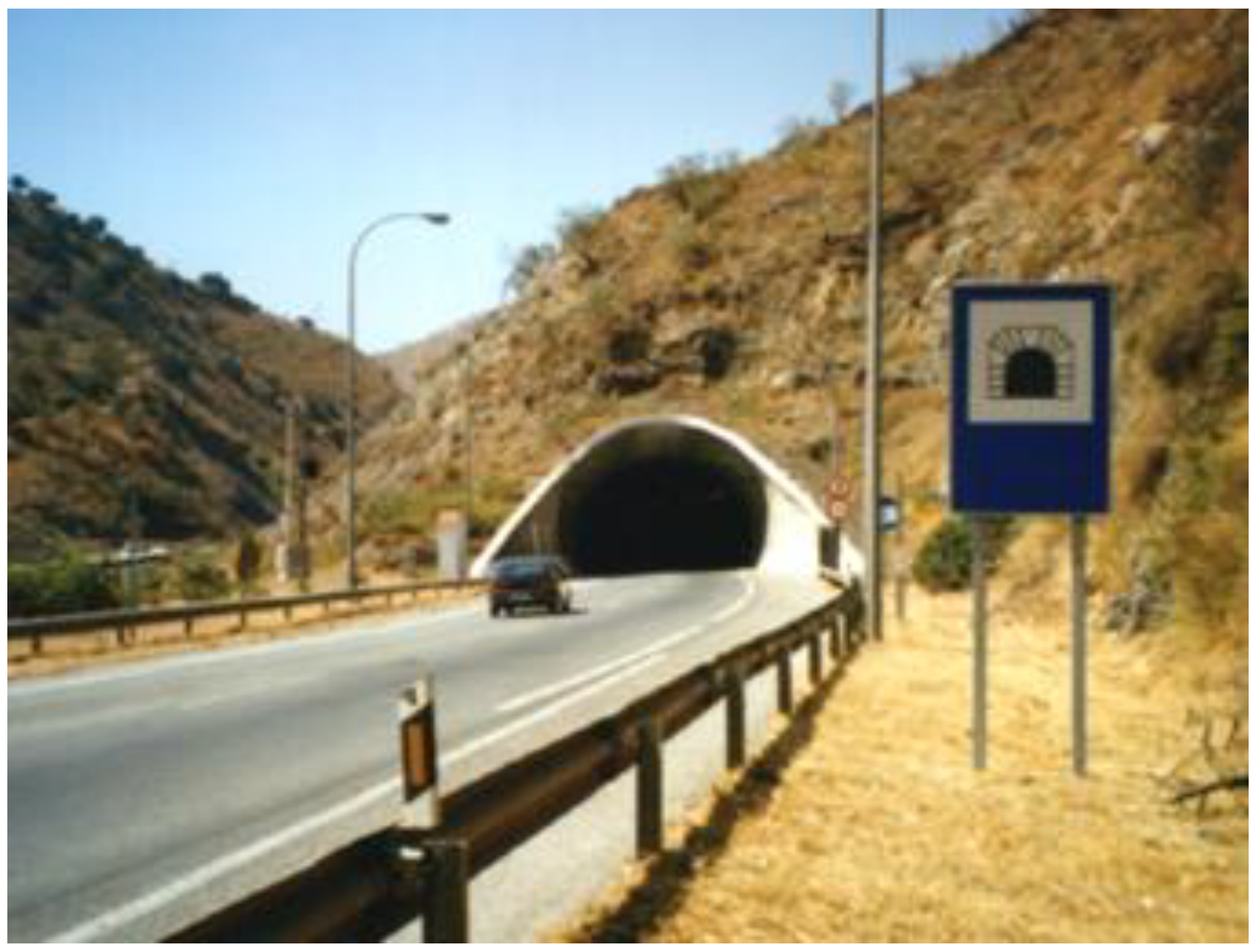
Figure 2.
Succession of dark and bright bands in one road tunnel.
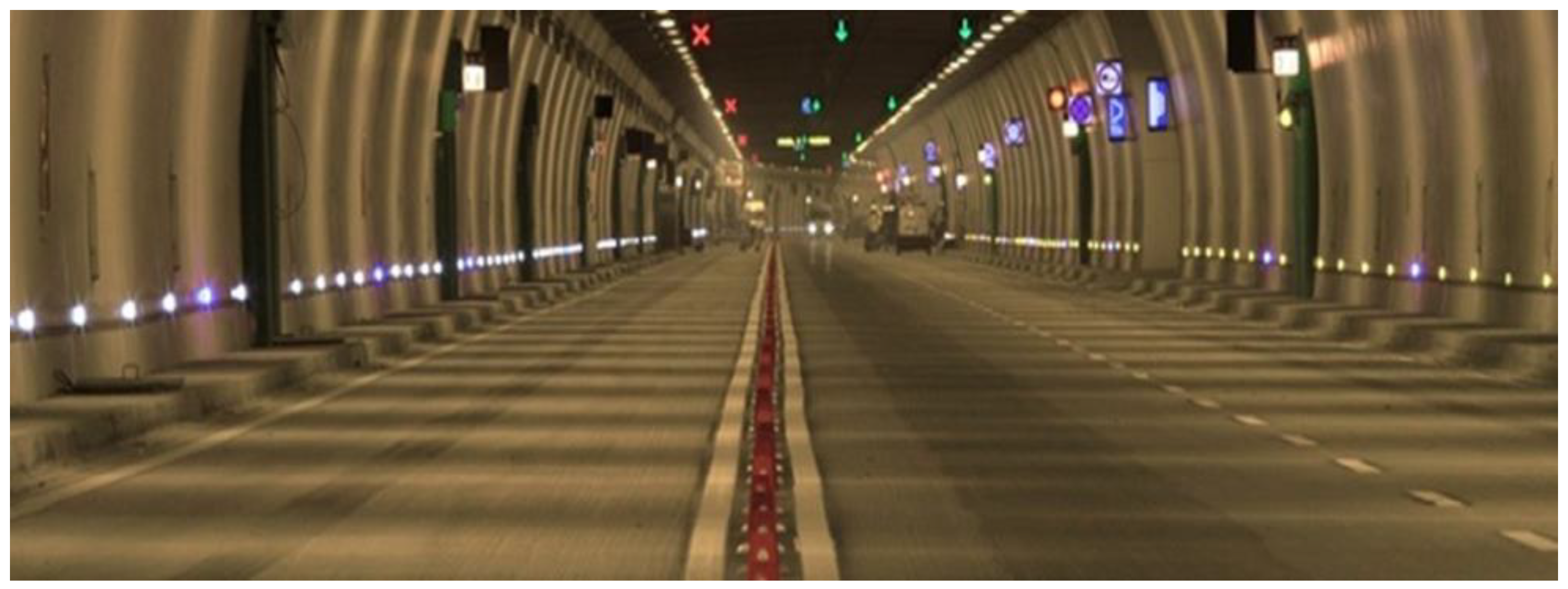
Figure 3.
Continuous stripes of LED to minimize flicker effect in the interior zone of tunnels and long underground roads.
Figure 3.
Continuous stripes of LED to minimize flicker effect in the interior zone of tunnels and long underground roads.
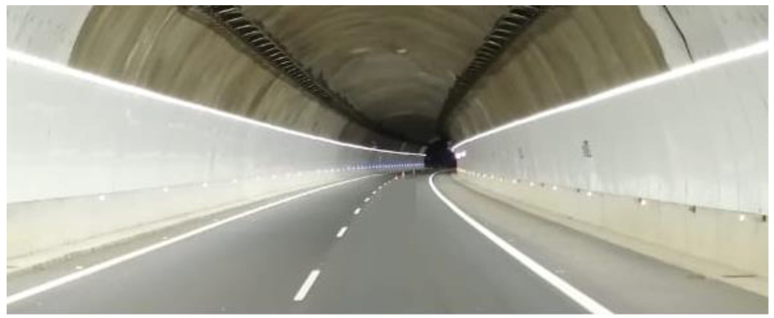
Figure 4.
Coupled system to inject and distribute sunlight in the interior of road tunnels [32].
Figure 4.
Coupled system to inject and distribute sunlight in the interior of road tunnels [32].
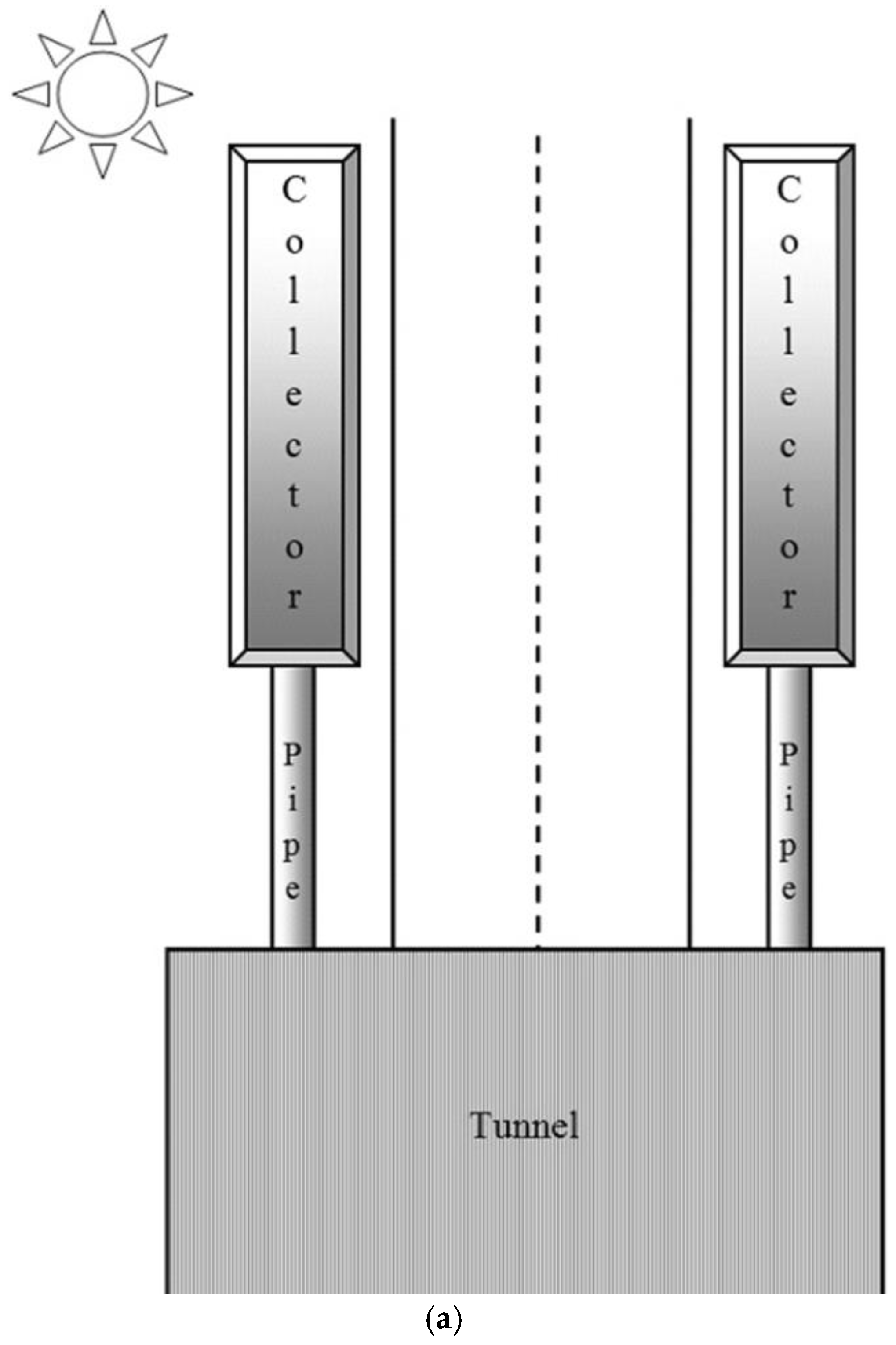
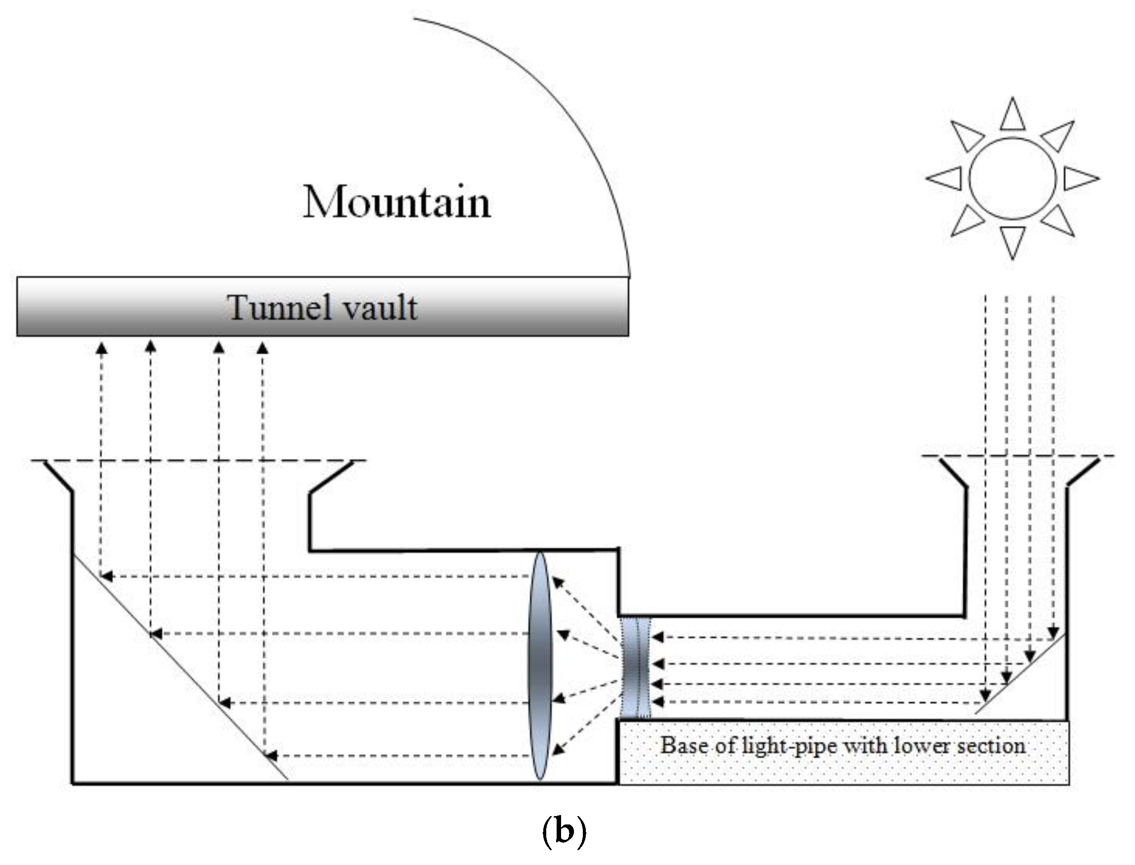
Figure 5.
Radiative exchanges for a pair of freely evolving surfaces, namely A1 and A2.
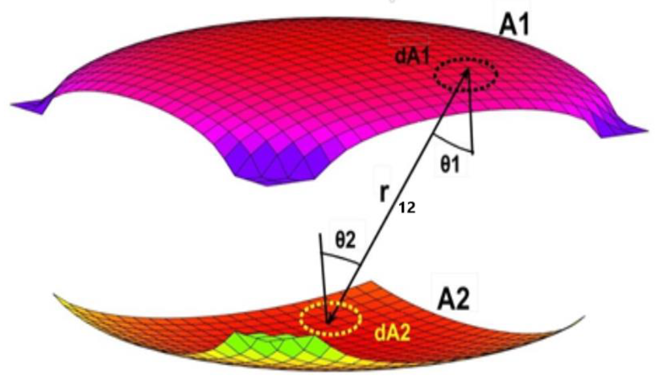
Figure 6.
Different dimensions of the equation for the innovative geometry.
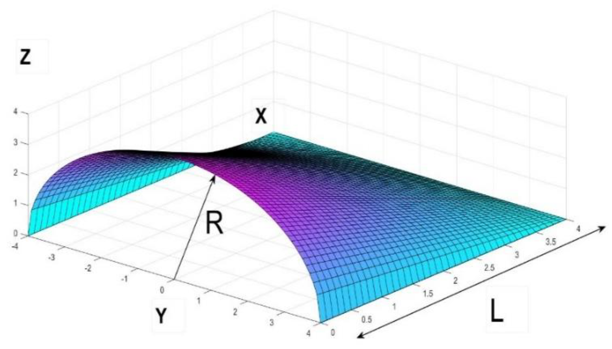
Figure 7.
Different views and sections of the innovative geometry of the tunnels showing curvature differences.
Figure 7.
Different views and sections of the innovative geometry of the tunnels showing curvature differences.
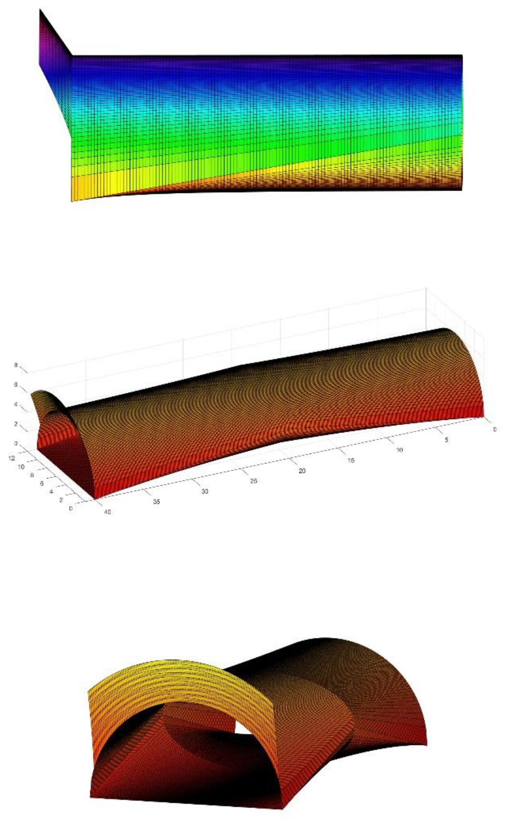
Figure 8.
Configuration factor between a rectangle and a point at an inclined plane with angle φ.
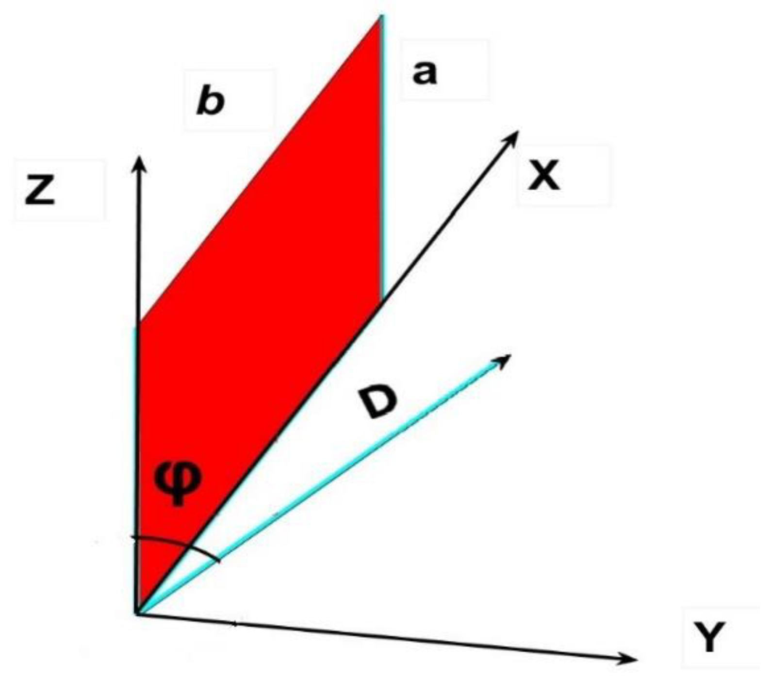
Figure 9.
Light distribution offered by the geometric model in [33].
Figure 9.
Light distribution offered by the geometric model in [33].
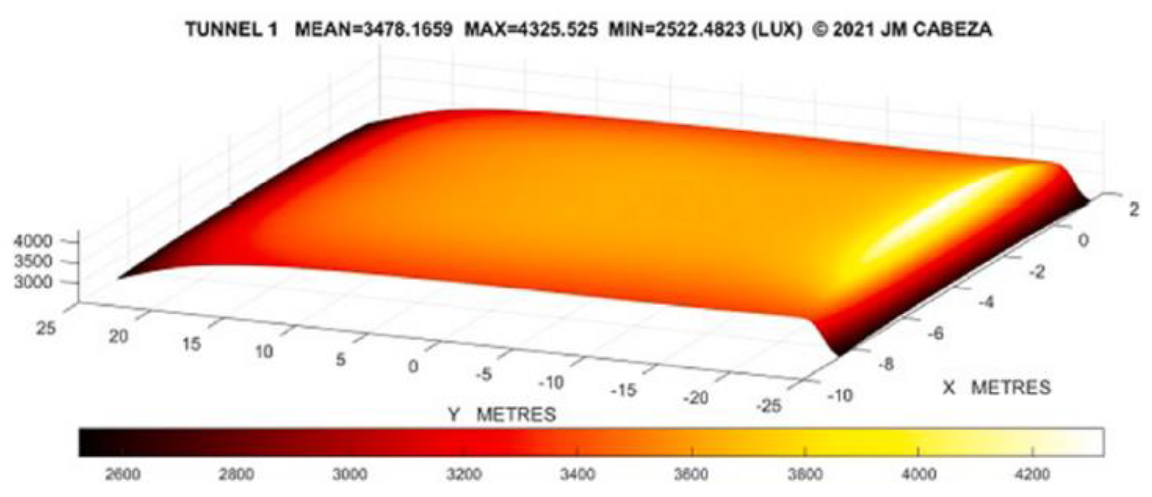
Figure 10.
Cross corner of two linear connections.
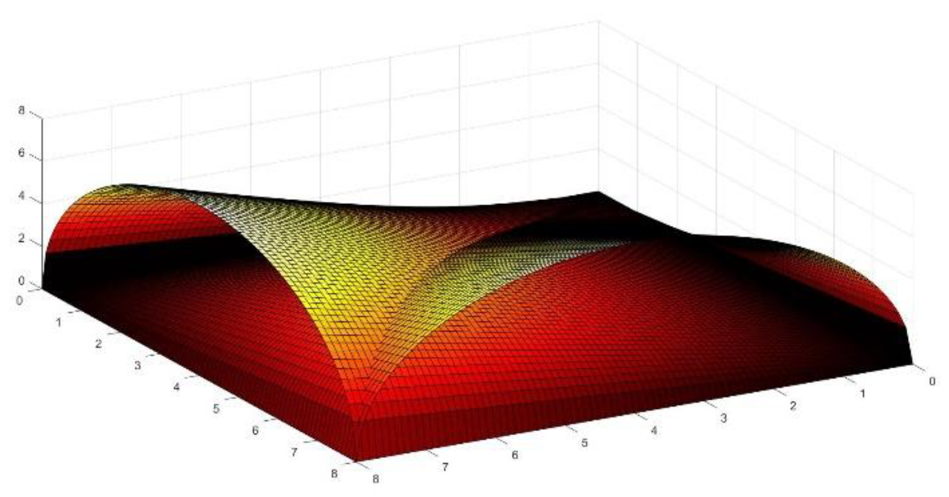
Figure 11.
Crossing of four passageways.
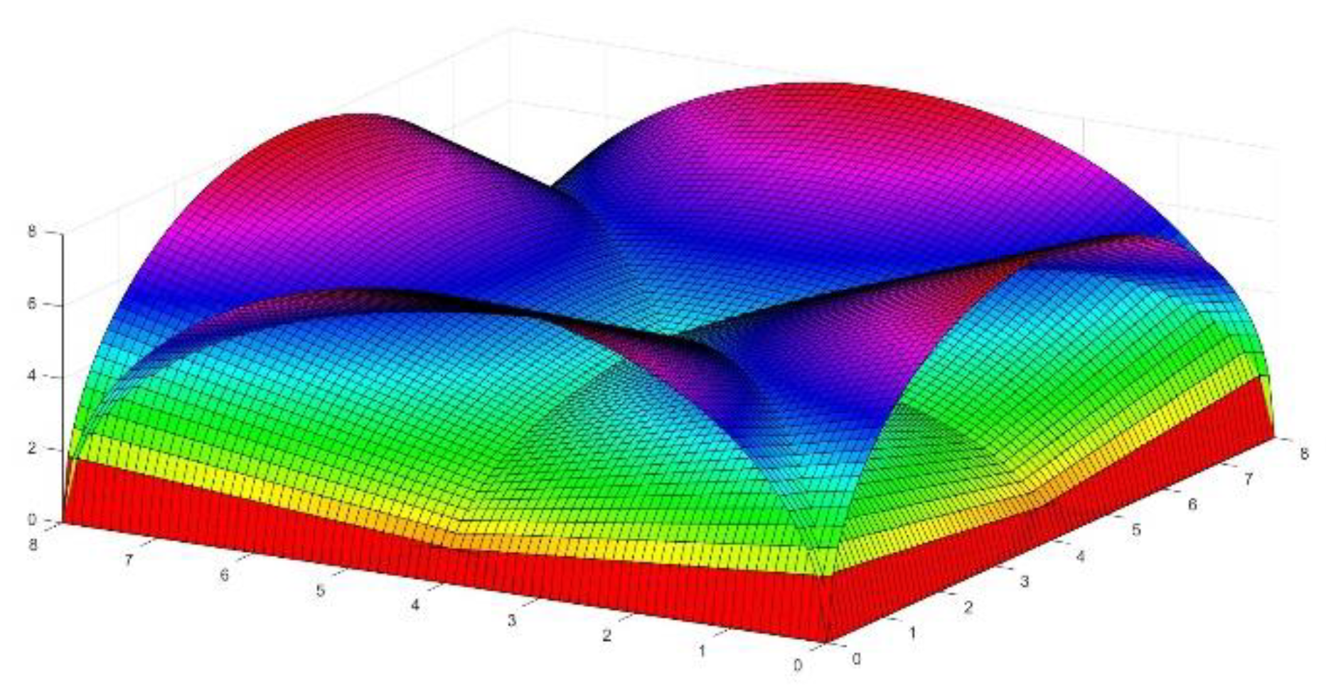
Figure 12.
Scale Model of Crossing adapted to four linear connections.
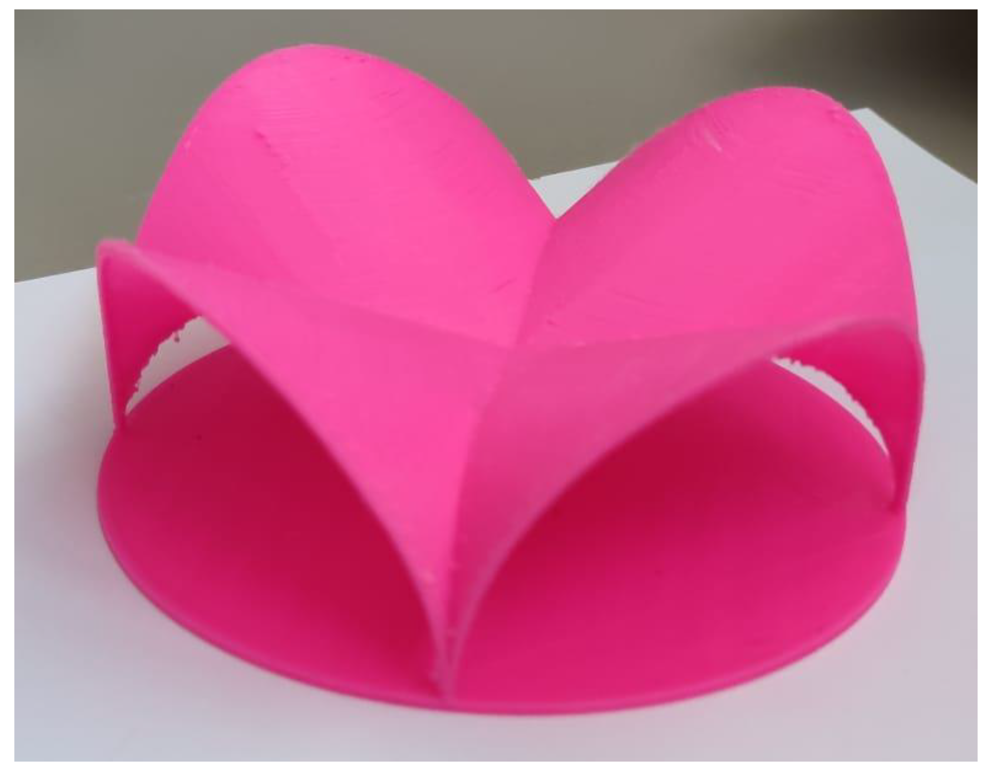
Figure 13.
Extended Model for the above junction of four connections.

Figure 14.
Perspective view of the model of four connections.
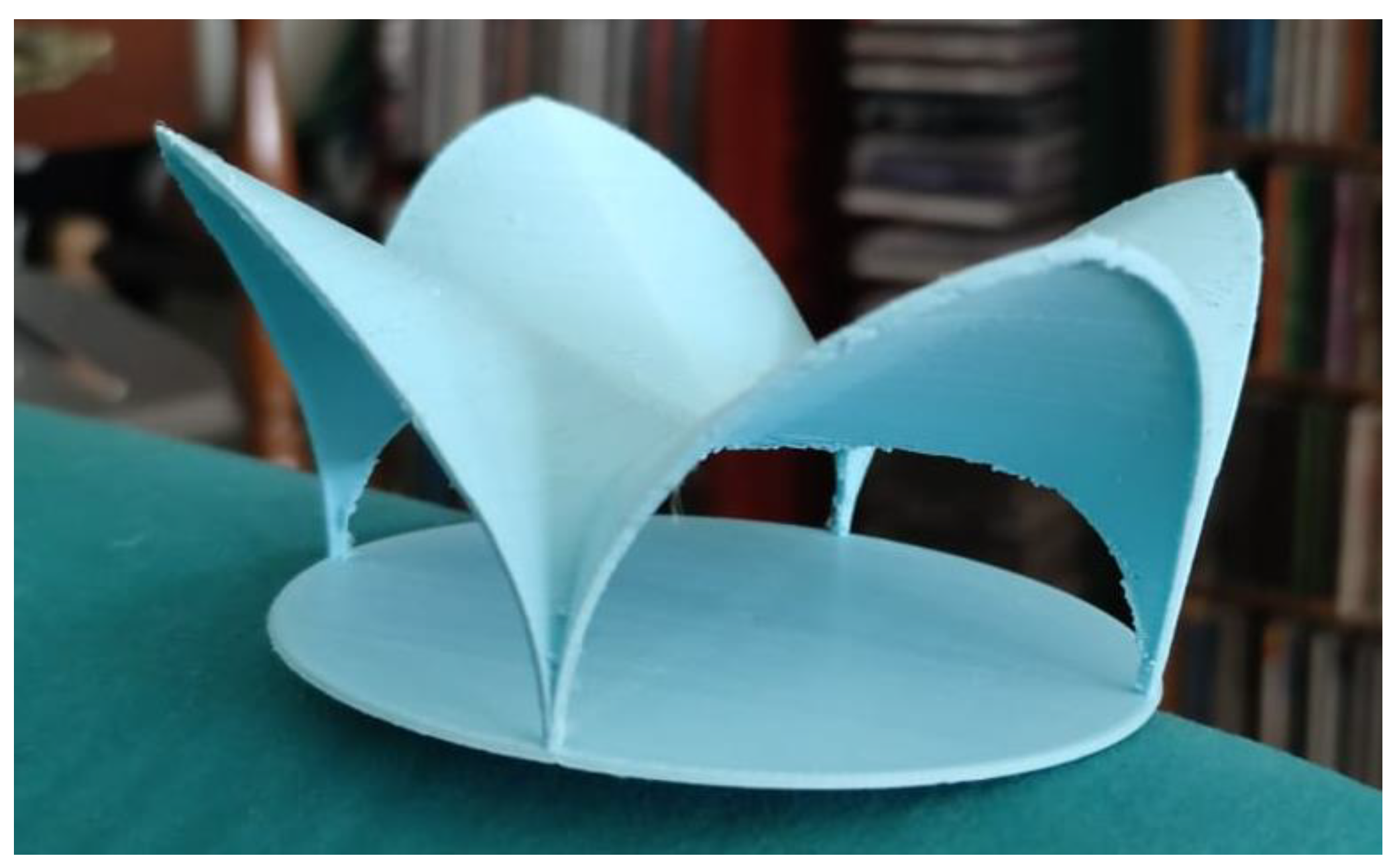
Figure 15.
Model for a special triangular crossing.
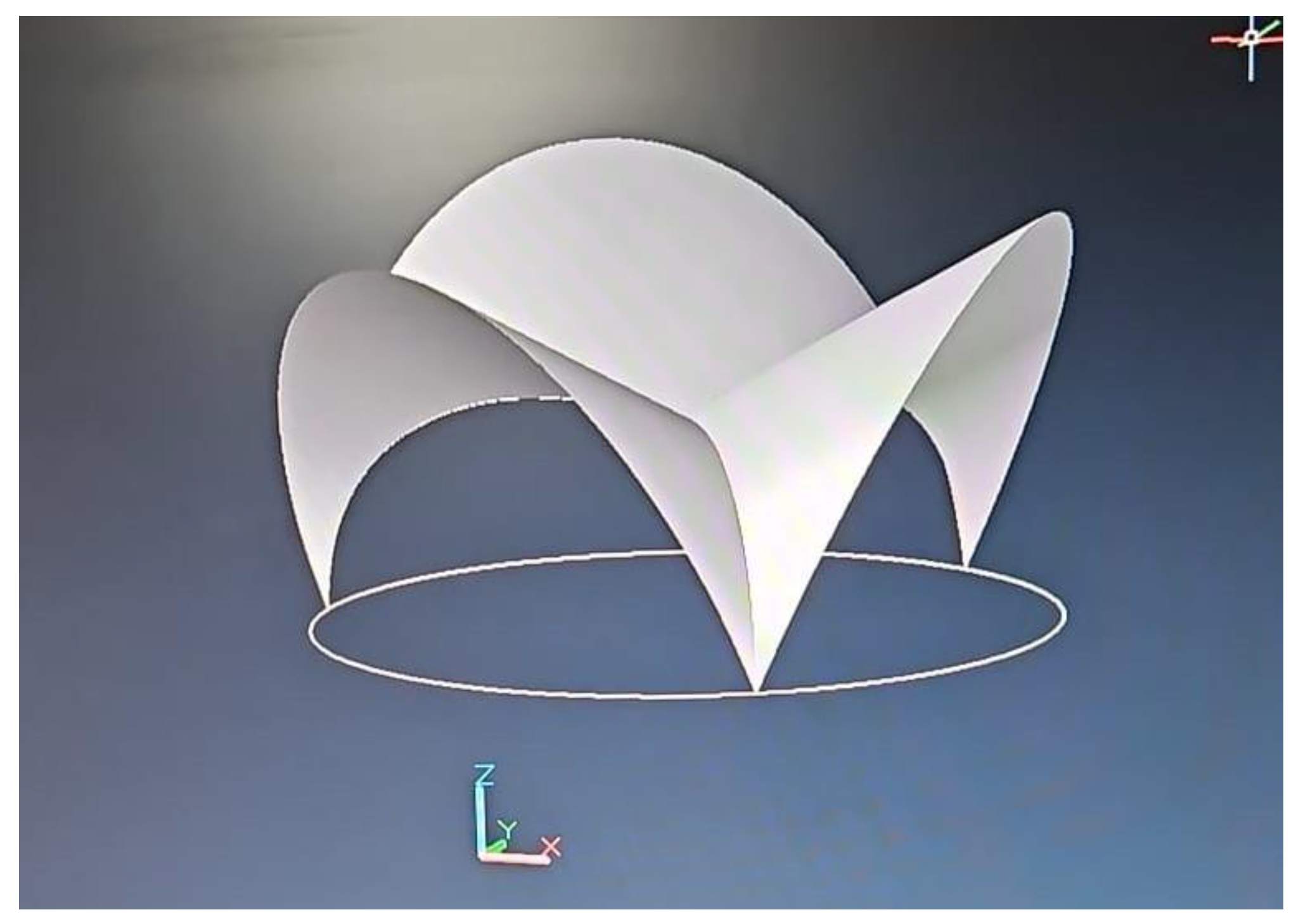
Figure 16.
Scale model designed for inclined connection between two horizontal planes at different height levels which implies 3D connectivity.
Figure 16.
Scale model designed for inclined connection between two horizontal planes at different height levels which implies 3D connectivity.
Figure 17.
Real size model of the interconnection of tunnels constructed to monitor different parameters.
Figure 17.
Real size model of the interconnection of tunnels constructed to monitor different parameters.
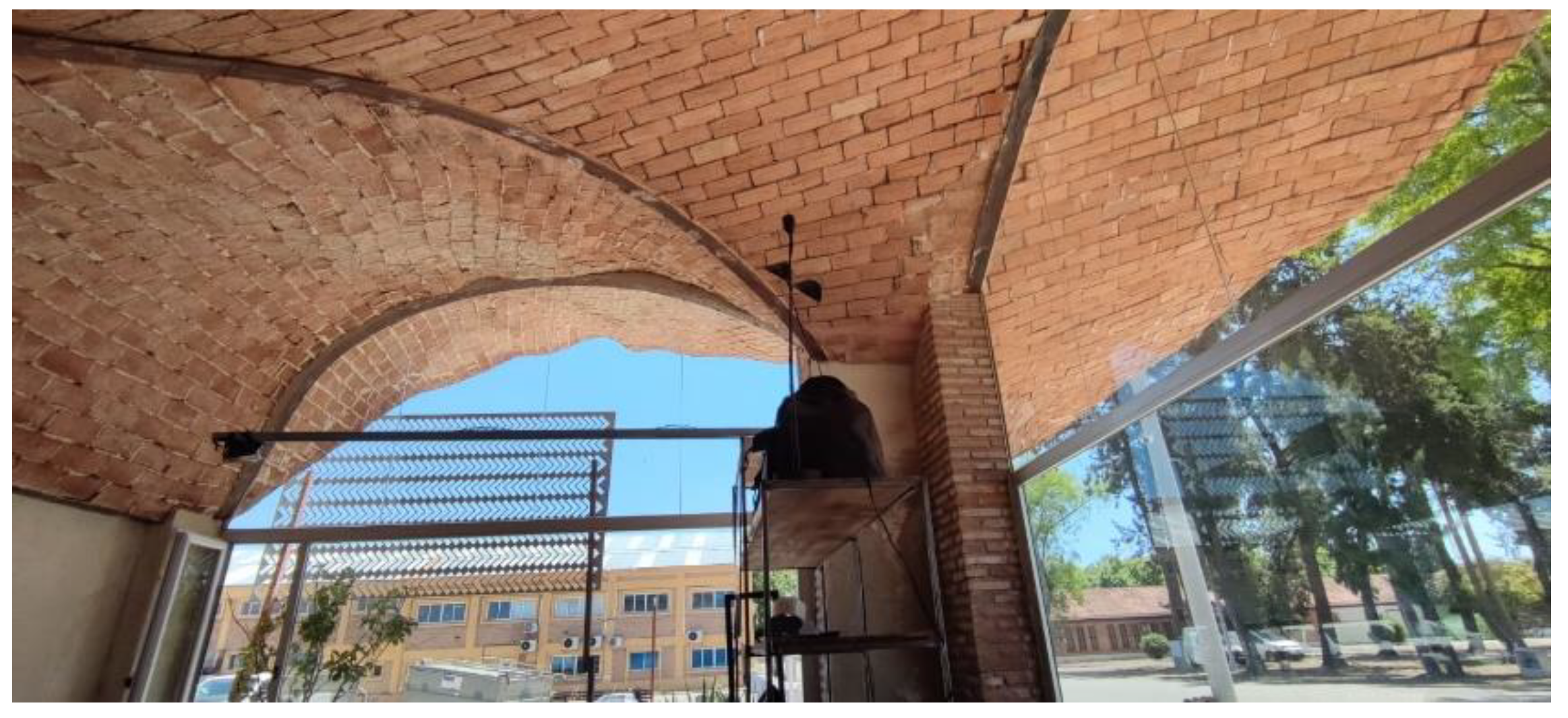
Figure 18.
Experimental model of the reflective ceiling of the tunnel before coating. Seville.
Disclaimer/Publisher’s Note: The statements, opinions and data contained in all publications are solely those of the individual author(s) and contributor(s) and not of MDPI and/or the editor(s). MDPI and/or the editor(s) disclaim responsibility for any injury to people or property resulting from any ideas, methods, instructions or products referred to in the content. |
© 2025 by the authors. Licensee MDPI, Basel, Switzerland. This article is an open access article distributed under the terms and conditions of the Creative Commons Attribution (CC BY) license (http://creativecommons.org/licenses/by/4.0/).
Copyright: This open access article is published under a Creative Commons CC BY 4.0 license, which permit the free download, distribution, and reuse, provided that the author and preprint are cited in any reuse.


