Submitted:
03 June 2025
Posted:
06 June 2025
You are already at the latest version
Abstract
By allowing the production of complicated geometries with less tooling and material waste, Additive Manufacturing (AM) is transforming the fabrication of parts. The objective of this study is to compare the feasibility and performance of two AM techniques, Fused Deposition Modeling (FDM) and Stereolithography (SLA) to produce snap-fit plastic parts. The study specifically investigates how process parameters and prints orientation affect defect formation, dimensional accuracy, and structural suitability. The parts were assessed through qualitative defect analysis and quantitative dimensional measurements. Additionally, the effect of build orientation and support structure design was evaluated. A mathematical model was applied to estimate and validate printing time based on layer height. SLA parts demonstrated superior dimensional accuracy, with average deviations significantly lower than those observed in FDM prints. However, SLA was more prone to support-induced surface damage and brittleness. FDM produced structurally stronger but dimensionally less accurate parts, affected by brim residues and sagging. The validated print time model further confirmed the reliability of predictive manufacturing planning. Although AM, particularly SLA, seems encouraging for creating exact, low-volume snap-fit assemblies, both methods have their own difficulties. While FDM is preferable for fast prototyping of mechanically strong components, SLA is appropriate for applications needing critical details. The results underline AM's present constraints for mass production even if they show promise in generating tailored functional components.
Keywords:
design for additive manufacturing
; snap-fit assembly
; fused deposition modeling
; stereolithography
1. Introduction
The invention of additive manufacturing (AM), commonly known as 3D printing, completely changed how we implement design and production. Unlike traditional subtractive methods that take material from a solid block to create desired forms, AM works by successively layering material to build parts from the ground up using digital CAD models. This change in manufacturing has allowed for the creation of very complicated, lightweight, tailored geometries, reducing material waste, and rapid prototyping. Because of these advantages, AM are gaining popularity across a wide range of industries, including consumer goods, electronics, biomedical, automotive, and aerospace[1,2]. Among the various design considerations in AM, the integration of snap joints has gained growing popularity due to the potential for simplifying assembly processes and improved product functionality. Snap-fits are essential mechanical components often found in plastic parts that allow interlocking assembly without the use of fasteners, adhesives, or welding. Their simplicity, affordability, and reusability have made them common in electronic enclosures, automotive interiors, packaging solutions, and consumer product housings [1,3].
Various manufacturing techniques can be used to create snap-fit joints, and each has unique benefits based on the material needs, volume of production, and complexity of the design [4,5,6,7]. The most widely used method for mass-producing plastic snap-fits is still injection molding because of its exceptional dimensional accuracy, reproducibility, and compatibility with a variety of thermoplastics [3,8,9,10]. While CNC machining is usually utilized for prototyping or for generating snap-fit components from engineered plastics or metals, thermoforming is a more affordable choice for creating thin-walled parts [11,12,13,14]. Die casting makes it possible to incorporate intricate snap features into cast metal components, whereas stamping and shaping are popular methods for metal-based snap mechanisms in high-volume sheet metal applications. Table S1 provides a summary of the importance of various manufacturing method used for snap fits. Additive manufacturing (AM) has become a competitive alternative for low-volume production and prototyping in recent years, particularly for customized snap-fit designs or geometrically challenging designs [1,3].
AM technologies allow for the practical and inexpensive fabrication of complex geometries that are not possible with conventional manufacturing techniques. According to Klahn et al. [15], AM’s geometrical freedom can help create functional snap-fit components that improve product functionality and simplify assembly. AM’s versatility makes it possible to produce a wide range of materials and forms, which is particularly useful in applications like the assembly of modular wind turbine blades, where snap-fit joints can lower weight and increase structural integrity [16]. According to Guo and Sun’s research on assembly/disassembly mechanics, snap-fit joint performance is greatly influenced by the interplay of geometric design, elasticity, and material properties [9,10]. Their study highlights how crucial finite element analysis (FEA) is as a tool for snap-fit design optimization and assembly force prediction for a range of materials. Furthermore, Li et al. recommend the use of shape memory polymers, which improve the functionality of snap-fits by allowing components to achieve a stable configuration after assembly [17]. This development suggests that novel materials and cutting-edge additive manufacturing processes can be combined to increase the dependability of snap-fit assemblies. Table S2 provides an in-depth assessment of significant research on snap-fit design and additive manufacturing. It covers advancements in hybrid manufacturing, DFMA methodologies, structural modeling, and performance evaluation using simulation and experimental validation. The assessment highlights AM’s expanding capabilities in achieving mechanical dependability, cost efficiency, and integration in a wide range of applications, including automotive, timber constructions, and fixture manufacturing.
Two commonly used AM technologies with different operating principles and material systems are Fused Deposition Modelling (FDM) and Stereolithography (SLA) [2,5,18,19,20]. However, the resolution, surface finish, and mechanical characteristics of AM methods FDM and SLA differ, which may have an impact on the snap-fits’ functional performance. Designing snap-fits, therefore, calls for careful consideration of dimensional tolerances, material flexibility, strain limits, and stress distribution, all of which can be greatly affected by the manufacturing method used [15,20,21,22]. Although FDM is cost-effective and widely available, its layered thermoplastic extrusion usually results in lower surface polish and dimensional accuracy. In contrast, SLA uses a laser to cure liquid photopolymer resin, resulting in higher resolution and smoother surfaces, albeit with increased brittleness and sensitivity to post-processing [2,23,24].
While additive manufacturing is increasingly being used for both prototyping and end-use functional components, there is a noticeable lack of comparative research evaluating its performance for snap-fitting applications. Although previous research has focused on dimensional tolerances and basic mechanical properties such as tensile strength in AM-produced parts [1,3,25], the literature often overlooks application-specific performance parameters critical to snap-fit design, such as beam deflection, interlocking retention forces, and durability under cyclic loading. Given AM’s growing reliance on mechanically dependable and dimensionally accurate components, particularly in consumer electronics and automotive assembly, bridging this research gap is critical to enable its widespread use in snap-fit applications.[9,10,26,27].
The current work attempts to systematically assess the suitability of FDM and SLA technologies for creating effective snap-fit assemblies to fill this research gap. A custom-designed bag clip was chosen as the case study due to its practical use, geometric complexity, and mechanical interactivity. The study focuses on crucial parameters that affect snap-fit performance, such as defect generation, dimensional accuracy, build orientation, and support structure effects. Both qualitative and quantitative analyses were carried out, along with time-based performance modeling, to provide a comprehensive evaluation of each method’s capabilities and limits in manufacturing mechanically functional snap-fit components. Additionally, it provides actionable design-for-additive-manufacturing (DfAM) insights for engineers offering practical implementation of AM in mechanically reliable snap-fit applications
2. Materials and Methods
Two AM technologies were employed for fabrication:
-
Fused Deposition Modeling (FDM):
- Machine: Ultimaker 3
- Material: Polylactic Acid (PLA)
- Settings: 0.1 mm layer height, 100% infill, Brim adhesion, supports enabled
- Orientation: Aligned to optimize strength along stress-bearing lines
- Printing Temperature: 200 °C
- Build Plate Temperature: 60 °C
-
Stereolithography (SLA):
- Machine: Formlabs Form 2
- Laser: 405 nm Wavelength, 250 mW
- Resin Tank Temperature: 35 ºC
- Laser Spot Size: 140 microns
- Peel Mechanism: Sliding Peel process with Wiper
- Material: Methacrylate-based photopolymer resin
- Settings: 0.05 mm layer height, minimal touchpoint supports, optimized tilt orientation
- Orientation: Angled to reduce peel forces and support marks on functional surfaces

Table 1.
Time Taken for Printing.
| Parameter | FDM | SLA |
|---|---|---|
| Layer Thickness | 0.1 mm | 0.05 mm |
| Number of Layers | 275 | |
| Build Material | 15 grams | 17.17 mL |
| Time to Print | 4 hrs 18 min | 2 hrs 9 min |
Layer height and support configurations were selected to balance resolution, print time, and structural reliability:
FDM: 0.1 mm chosen to enhance detail without excessive print duration; Brim adhesion minimized warping.
SLA: 0.05 mm enabled high-resolution feature replication critical to snap-fit engagement.
Build orientations were optimized based on process-specific considerations:
FDM: Layers oriented perpendicular to bending forces to enhance flexural strength.
SLA: Angled positioning reduced suction artifacts and improved support accessibility.
This methodology ensured consistency in comparative analysis across both printing technologies, isolating process-specific impacts on dimensional accuracy and mechanical performance.
Figure 1.
Methodology flowchart.
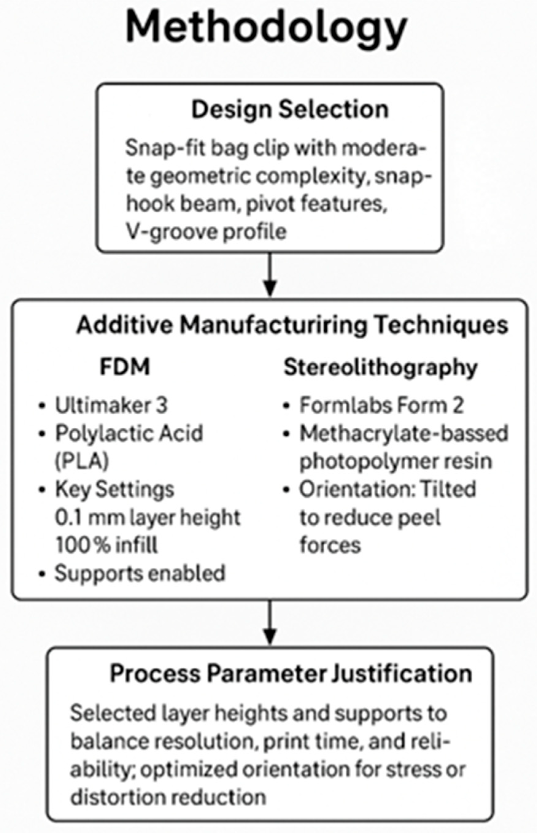
Design Selection
The snap-fit component selected for this study is a bag clip featuring moderate geometric complexity and clear functional requirements as shown in Figure 2. The design was chosen to demonstrate the interplay between additive manufacturing constraints and snap-fit mechanics. Key geometric elements included:
- Snap-hook beam: Ensures locking functionality and controlled deflection.
- Pivot features: Allow rotational movement for opening/closing.
- V-groove profile: Facilitates sealing and alignment during assembly.
This part was designed using standard DfAM principles, emphasizing overhang minimization, feature reinforcement, and consistent wall thickness.
Although these two parts seem simple, manufacturing them using conventional injection molding technique will be very difficult. The outline of features that make injection molding difficult for the snap fit joint is shown in Figure 3. A side-pull mechanism in the X direction is required to generate the snap-hook feature labelled as “a” in the Figure 3, and another in the Z direction to form the circular hollow at the bottom right as labelled “c”. The relief feature designated as “b” is difficult to mold. To accommodate undercut features, side pulls would also be required when molding the part from the Z or X orientations.
3. Results:
3.1. Qualitative Defect evaluation
A detailed visual inspection was conducted to identify common process-induced defects across both additive manufacturing techniques. FDM parts showed defects such brim residue, infill voids, and overhang sagging due to material extrusion dynamics and support limitations. The surfaces of the STA parts were smoother, but they also had resin-specific defects such touchpoint scars, edge chipping, and localized sagging near unsupported or overhanging areas. Curing-induced brittleness also resulted in microcracks during post-processing and handling. These qualitative defects directly influenced the surface finish, aesthetic quality, and mechanical integrity of the parts, necessitating design and support strategy refinements.
Figure 4 shows a single hole feature of Part 1 that had a one-time defect that was supported with auxiliary material. While other hole features were printed accurately, this particular defect appears to be due the insufficient support density, which results in inadequate surface stability during layer deposition. Consequently, the filament strands sagged, resulting in a distorted circular profile and poor surface finish.
Figure 5 shows residual brim material on the surface of Part 1 resulting from the brim removal, an auxiliary, single-layer-thick boundary used to improve build plate adhesion and minimize warping. Despite being effective in preventing deformation, the brim was difficult to remove thoroughly, leaving behind undesired surface residue.
Figure 6 shows the internal voids in Part 1 that were caused by rasterization errors made during the slicing procedure. The likely cause is inadequate infill overlap with 15% of the default setting in Cura (software for Ultimaker 3). To eliminate such defects and guarantee adequate bonding between infill and perimeter walls, it might be essential to increase this parameter.
Figure 7 shows two surface defects observed in Part 2. During the removal of the brim layer, the part geometry suffered partial damage as shown in Figure 7 (a). In Figure 7 (b), roughness and stringing are visible around the inner hole cavity, where the portion interfaced with support structures. These defects most likely resulted in the filament sagging and locally poor surface quality because of non-uniform or insufficient support beneath the surface.
Figure 8 shows the various type of surface defects resulting by the SLA support removal procedure. The rough surface in Figure 8 (a) was generated by protrusions at the support contact locations. A support removal tool accidentally created a cavity as shown in Figure 8 (b). The cured photosensitive resin is essentially soft, and needs supports to hold its weight. Figure 8 (c) shows that for the large spacing between supports due to an inadequate support density, failed to properly bear the part’s weight, resulting in sagging and general deformation. The overall shape of the part also looked bent due to this reason. Figure 8 (d) and (e) shows the brittleness of cured resin and the sensitivity of fine features to post-processing tools highlighted by the chipping that happened at sharp edges during support removal.
3.2. Quantitative Dimensional Accuracy
To guarantee appropriate engagement, alignment, and mechanical performance, accurate dimensions are essential. Dimensional measurements were taken for critical functional features labeled in Figure 9 such as, overall thickness and pivot gap to assess manufacturing precision. The plot of measured dimensional values versus measurement sequence number for critical features of Part 1 dimensions (a) and (c) measured using vernier calipers, and Part 2 dimension (e) measured using a micrometer are shown in Figure 10. This plot illustrates dimensional consistency and variability across multiple samples. Figure S1 shows the comparison of measured values of the printed part features with nominal CAD dimensions, showing variances and trends in precision particular to the process. A micrometer’s superior least count of 0.001 mm over vernier calipers’ 0.01 mm makes it the ideal tool for measuring part thickness. However, the snap-hook feature restricted access for Dimension “a” on Part 1, making the use of micrometers impractical. Despite having less precision, vernier caliper were better suited for measurement of Part 1 dimension “c”, because in this situation they could reach small, offset features. However, the dimension measurement Part 1 “c” was impacted by the measurement uncertainty brought about by the Abbe errors trade-off. We used an optical profiler to measure the angled surface that corresponded to Part 1 dimension “d,” since it offered appropriate surface mapping capabilities. The measurement was dependent on user interpretation because it lacked a digital display, while being easily accessible and convenient in the LMP shop. Furthermore, Part 1 dimension “d” had a measured value of 45 mm with no apparent variation across FDM and SLA prints, suggesting high consistency in this feature. A micrometer, which was more accessible and provided greater accuracy than vernier calipers, was used to measure the dimension “e” on Part 2. A dial indicator was used to assess flatness in order to quantify out-of-plane distortion that was introduced during the SLA process. A maximum height difference of 0.5 mm was observed. SLA parts had consistently higher dimensional accuracy than FDM ones, with measurements closer to the specified CAD values. The main reasons for this are the finer resolution of SLA, which is controlled by a 140 µm laser spot size and regulated layer thickness, as well as the reduced shrinkage and thermal distortion that occur during curing. In contrast, FDM accuracy is extremely sensitive to thermal interactions, bed leveling, raster angle, and component design with asymmetric shrinkage often leading to warping. The first FDM layer also adds to base-wide distortion since it is printed at higher flow rates for adhesion. Additionally, 100% infill may result in material overlap, which would further enlarge the dimensions.
Comparative thickness and pivot gap dimensional variations for FDM and SLA printed snap-fit assemblies are displayed in Figure 11. SLA products showed better dimensional accuracy than FDM parts, with mean deviations of +0.16 mm for thickness and +0.04 mm for pivot gap, respectively, versus +0.29 mm and -0.26 mm for FDM. SLA’s controlled curing environment and smaller laser spot size of 140 µm vs. FDM’s 400 µm nozzle contributed to its enhanced precision. These finding confirm that SLA achieved better overall dimensional accuracy, especially in tight tolerance areas. In contrast, FDM showed greater dimensional variability, which was probably caused by inconsistent filament deposition and thermal contraction effects.
3.3. Effect of Orientation and Support Structures
Print orientation and support configuration significantly influenced both accuracy and mechanical performance. Figure 12 shows the snap-fit part orientation chosen for both SLA and FDM process in the present research. Table 2 presents the summary of dimensional performance, surface quality, and post-processing challenges for FDM and SLA. For a snap fit assembly, it is essential to ensure that neither the snap-hook nor the main body part fails during operation. The snap-hook experiences loading like a cantilever beam whereas the main clip structure behaves like a simply supported beam under bending. In such cases, the material above the neutral axis is subjected to tension and the material below is in compression. As per the process physics for FDM, the tensile strength of the part is maximum along the direction of the filament. Therefore, optimal strength can only be achieved by aligning print orientation with the primary load paths. Thus, the orientation where we can maximize the tensile strength of the snap-fit assembly is the one chosen for this application
FDM Orientation Strategy:
Parts were oriented along the axis of applied stress to enhance inter-layer adhesion and structural strength. This alignment improved mechanical durability but contributed to surface roughness on the side-exposed surfaces.
SLA Orientation Strategy:
SLA parts were tilted to reduce peel forces during layer separation and to minimize support interference with critical surfaces. While this improved surface fidelity on functional zones, it increased reliance on minimal touchpoint supports, which in turn caused localized deformation and edge damage during removal.
In both processes, support structures were essential for maintaining geometric integrity. However, ease of support removal and the extent of post-processing defects varied significantly, with SLA being more sensitive to improper orientation or insufficient support density.
Supports structures played a critical role in both the FDM and SLA processes due to the presence of numerous overhanging features in the part. In FDM, supports were strategically placed beneath these features; however, the surface quality of the layer printed immediately above the support material was rough and did not give a good surface finish. This issue could potentially be resolved by increasing the density of the support material. Figure 13 shows the support material arrangement and low support density in critical area in FDM. For SLA also, support is essential to hold the part in place when the wiper peels off the layer from the PDMS surface of the tank. In this study, the density of the support material was not optimal which caused local sagging of the material between the supports as discussed previously. Unlike FDM, which may allow for multi-material printing and easier support removal, SLA relies on a single material and triangulated structure supports with small touch points making post processing more challenging.
3.4. Microstructure and post-processing
The microstructural differences between FDM and SLA significantly influenced the mechanical performance and surface quality of the fabricated snap-fit parts. Figure 14 shows the print microstructure for SLA and FDM parts. FDM produced a layered microstructure with visible inter-layer and internal voids, leading to anisotropic mechanical behavior and reduced strength under loads perpendicular to the build direction. While post-processing for FDM was relatively straightforward, involving removal of brim and minor sanding, it did not significantly improve surface quality. FDM parts exhibited rougher surfaces with visible layer lines and minor delamination at unsupported overhangs. Conversely, SLA utilizes a photopolymerization process in which a laser cures liquid resin layer by layer. This results in a more continuous and homogenous microstructure, offering higher resolution and reduced porosity, but the cured resin’s brittleness and difficult support removal introduced risks of cracking or edge chipping during handling or post-processing. Surface finish is smoother in SLA parts, through defects such as sagging due to peel forces during the printing process and resin residue in less accessible areas were observed.
In summary, while SLA offers superior microstructural fidelity and aesthetic finish, it introduces post-processing complications that can compromise functional reliability. FDM, though inferior in precision and finish, provided better resistance to post-processing damage due to its ductile thermoplastic nature. These differences are critical when selecting an AM process for snap-fit applications requiring both dimensional fidelity and mechanical robustness.
Figure 15 shows the several failed prints which occurred during the fabrication process. Non-uniform filament extrusion and under-extrusion caused missing layers and poor structural integrity in FDM utilizing the Makerbot printer. Additionally, an attempt to print the snap-fit assembly using the SLA process failed due to fusing of features close to the hinge region, probably caused by insufficient clearance and overcuring. These failures highlight the importance of process optimization and design adaptation for reliable additive manufacturing results.
3.5. Process Modeling and Print Time
The volumes of the model and support materials, layer height, and component height are the main factors affecting print time. The overall print duration is also significantly influenced by other variables, including the number of repositioning movements, the total contour length per layer which is linked to the nozzle diameter, and the print speed for the model and support materials. Figure 16 shows the relationship between layer thickness and printing time for the case of FDM process. To assess the production feasibility of additive manufacturing techniques for snap-fit assemblies, a mathematical model was developed to estimate the print time as a function of layer height. This predictive model aimed to support production planning by enabling early estimation of printing duration under varying resolution settings. An exponential decay model was used to describe the inverse relationship between layer height (x) and printing time (y) for FDM printing:
where:
y: Estimated printing time in minutes
x: Layer height in millimeters
This model was derived from empirical observations and regression fitting across multiple print runs with varying resolutions.
To verify the reliability of the predictive model, it was applied to the SLA process at a layer height of 0.1 mm. The model estimated the print time as approximately 273 minutes (4 hours and 33 minutes). The actual observed print time for the same configuration was 258 minutes (4 hours and 18 minutes), showing a deviation of just 15 minutes, thereby validating the model’s accuracy for practical use. The validated model provides a practical tool for workflow planning in the early stages of additive manufacturing. It makes resolution-based build time estimation possible, facilitates the assessment of speed-quality trade-offs, and aids in throughput forecasting for low-volume manufacturing. AM offers distinct benefits in prototyping and custom applications by increasing productivity and resource planning, even if it still takes significantly more time than traditional methods like injection molding for the identical snap-fit clip with less than 4 minutes.
3.6. Impact of Wall Thickness in FDM
One major problem with FDM printing was warping brought on by uneven part thickness. Uneven thermal shrinkage due to the variations in wall thickness resulted in distortion and partial separation from the construction surface as shown in Figure 17. This impact was especially noticeable in Part 2, where bending was caused by thicker areas cooling differently from nearby thin sections. Therefore, it is essential to design pieces with uniform wall thickness to reduce warping and guarantee dimensional stability in FDM printing.
4. Discussion
The comparative analysis of FDM and SLA for fabricating a functional snap-fit assembly underscores key insights aligned with Design for Additive Manufacturing (DfAM) principles. This section interprets the experimental findings, contextualizes them in real-world applications, and proposes practical design refinements to improve manufacturability and performance.
4.1. DfAM-Based Interpretation of Findings
One of the core principles of DfAM is tailoring designs to exploit the strengths and mitigate the limitations of specific AM processes. The superior dimensional accuracy of SLA, as evidenced by minimal deviations in thickness (+0.16 mm) and pivot gap (+0.04 mm) validates its capability for producing high-precision parts. However, the brittleness of SLA resin, along with its sensitivity to support-induced damage, highlights the need for cautious post-processing and careful feature orientation during print setup.
FDM, although less precise (+0.29 mm thickness deviation, −0.26 mm pivot gap), proved more resilient in terms of post-processing and handling. The layer bonding and material ductility made it suitable for applications where mechanical strength and field durability are prioritized over fine resolution.
4.2. Trade-Offs Between FDM and SLA
The findings indicate clear trade-offs between the two technologies:
FDM offers greater mechanical robustness and faster handling post-print, but suffers from inferior surface quality and dimensional inconsistency, particularly on overhangs and unsupported zones.
SLA delivers exceptional surface finish and accuracy, critical for snap-fit engagement features, yet it is prone to cracking, edge chipping, and longer post-processing time due to support removal and UV curing.
This dichotomy suggests that technology selection must be based on end-use requirements: if the part is for visual prototyping or low-stress applications, SLA is preferable; for functional prototyping or rugged usage, FDM is more practical.
4.3. Design Improvement Suggestions
The performance of both printing methods can be enhanced through specific design modifications:
Angled printing in SLA: By orienting the part at an angle, peel forces during print are reduced, minimizing distortion and sagging. This also helps in relocating support structures to non-critical areas.
Uniform part thickness: Maintaining consistent wall thickness throughout the part mitigates warping in FDM and reduces resin stress points in SLA, leading to more reliable print outcomes.
Higher layer thickness in FDM: Increasing the layer height from 0.1 mm to 0.2 mm can reduce print time without significant impact on structural integrity for non-critical surfaces, enhancing productivity.
These design adaptations not only improve print quality but also streamline post-processing and reduce material waste.
4.4. Industrial Applicability and Constraints
From an industrial standpoint, additive manufacturing proves viable for low-volume, high-customization production scenarios such as pilot runs, concept validations, or bespoke components. The flexibility in design, minimal tooling requirements, and digital-to-physical workflow make AM especially attractive for startups, R&D labs, and rapid prototyping environments. However, the unsuitability for mass production remains a fundamental limitation. When benchmarked against traditional processes such as injection molding where a single unit can be fabricated in under 4 minutes, the 4+ hour print cycle in AM becomes economically unfeasible for large-scale deployment. Furthermore, the need for extensive post-processing, especially in SLA, adds to turnaround time and operational complexity.
Ultimately, although AM is not a substitute for mass production of snap-fit components, it provides a strong alternative for precision, flexibility, and customization in low-volume and niche uses. Engineers and product designers thinking about AM for functional mechanical assemblies will find the design techniques and process insights produced by this research to be a useful road map.
Figure 18 shows the decision matrix comparing FDM and SLA across dimensional, mechanical, and operational parameters for snap-fit part manufacturing. In summary, this study highlights important trade-offs between FDM and SLA in snap-fit assembly additive manufacturing. SLA outperformed FDM in terms of dimensional accuracy, with average deviations of +0.16 mm for thickness and +0.04 mm for pivot gap, versus +0.29 mm and −0.26 mm, respectively. SLA produced smoother surface finishes as well, but because of support removal, it was more prone to brittleness, edge chipping, and post-processing issues. In contrast, FDM demonstrated more surface and internal flaws such rasterization voids and brim residue, but it also offered better mechanical performance, ease of handling, and increased robustness under repeated loading. Print quality and structural integrity were found to be greatly impacted by design changes, such as consistent wall thickness to prevent warping in FDM, angled orientation in SLA to reduce peel forces, and the right support density. Both FDM and SLA exhibit strong potential for low-volume, customized production of functional snap-fit components, especially when guided by design-for-additive-manufacturing (DfAM) principles. However, AM’s applicability for high-volume manufacturing is limited by its longer build times and post-processing activities.
Printing the snap-fit component with both FDM and SLA methods revealed various opportunities to improve design and print parameters to make it more suitable for additive manufacturing. In the SLA process, distortion caused by the Form 2 printer’s peel step can be decreased by angling the part to minimize peel area per layer. Local sagging due to poor support density indicates the need to minimize support spacing. Increasing layer thickness when surface polish is less important can enhance part strength and shorten print time. A slight increase in support density can improve layer deposition uniformity, but it must be weighed against throughput.
5. Conclusion
This study demonstrates that SLA is better suited for applications requiring close tolerances and fine detail, consistently outperforming FDM in dimensional accuracy and surface finish. However, limitations such as post-processing issues and brittleness restrict the widespread application of SLA in functional snap-fit assemblies. In contrast, while precision is lost, FDM offers a superior mechanical durability and post-print handling simplicity, therefore preferring its use in quickly iterated prototypes with structural needs. The results confirm that each AM technique exhibits distinct advantages and limitations that must be evaluated relative to specific design goals and functional requirements. Key limitations encountered during this study include:
- Variability in post-processing outcomes, particularly for SLA
- Constraints on generalizability due to a single-part case study
- Lack of mechanical stress testing to quantitatively validate functional endurance
Despite these limitations, the results establish that AM, especially when guided by Design for AM (DfAM) principles, is well-suited for low-volume, customizable production of snap-fit components. It enables flexible design iteration, reduces tooling costs, and supports rapid prototyping. However, AM remains economically and temporally unviable for high-volume manufacturing, particularly when compared to conventional injection molding. The results indicate that the AM offers significant potential for custom functional parts where complex geometry, design flexibility, and small batch production are prioritized over the need for speed or scalability. With continued advances in material science, process automation, and post-processing techniques, AM is poised to become an increasingly viable alternative in specialized production environments.
Supplementary Materials
The following supporting information can be downloaded at the website of this paper posted on Preprints.org.
Acknowledgements
We would like to thank Prof. Dave Hardt for advising us on this project.
Conflicts of Interest
The authors declare no conflict of interests.
References
- Gibson I, Rosen D, Stucker B, Khorasani M. Additive manufacturing technologies. Cham, Switzerland: Springer; 2021. Vol. 17, p. 160–186.
- Thompson MK, Moroni G, Vaneker T, Fadel G, Campbell RI, Gibson I, et al. Design for Additive Manufacturing: Trends, opportunities, considerations, and constraints. CIRP Ann Manuf Technol. 2016;65(2):737–60. [CrossRef]
- Collan M, Michelsen KE. Technical, Economic and Societal Effects of Manufacturing 4.0 Automation, Adaption and Manufacturing in Finland and Beyond.
- HARPER Timonium CA. HANDBOOK OF PLASTIC PROCESSES. A JOHN WILEY & SONS, INC., PUBLICATION; 2006.
- Ji J, Liu M, Li S, Zhang K. Cantilever snap-fit performance analysis for haptic evaluation. J Mech Des. 2011;133(12):121004. [CrossRef]
- Ngo TD, Kashani A, Imbalzano G, Nguyen KTQ, Hui D. Additive manufacturing (3D printing): A review of materials, methods, applications and challenges. Compos B Eng. 2018;143:172–96. [CrossRef]
- Yao X, Zhang H, Huang Y, Wu D. Cloud manufacturing for the 3D printing industry. Int J Adv Manuf Technol. 2018;94(1–4):437–51. [CrossRef]
- Mose BR, Son IS, Bae JW, Ann HG, Lee CY, Shin DK. Modified analytical method to calculate the assembly and separation forces of cantilever hook-type snap-fit. Proc Inst Mech Eng C J Mech Eng Sci. 2019;233(14):5074–84. [CrossRef]
- Guo XL, Sun B. Mechanics of A Thin-Walled Torus Snap Fit [Internet]. 2023. Available from: https://www.preprints.org/manuscript/202311.0599/v1.
- Guo XL, Sun B. Assembly and Disassembly Mechanics of a Cylindrical Snap Fit [Internet]. 2022. Available from: https://www.preprints.org/manuscript/202201.0076/v1.
- El Khatib IH, Mechanical Engineering BE, Analytics MSB, Khatib IH El. Integration of Additive Manufacturing with CNC Sheet Metal Fabrication for Hybrid Fixtures: Design and Implementation of Precision Assembly Interfaces. 2022.
- Dolah MS, Yussof RM, Haidiezul AHM, Ishak MI. Computational analysis in design and manufacturing processes. In: AIP Conference Proceedings. American Institute of Physics Inc.; 2018. [CrossRef]
- Cunningham AT. Integration of Additive Manufacturing with CNC Sheet Metal Fabrication for Hybrid Fixtures: Design and Implementation of Powder Bed Fusion Tooling Surfaces. 2022.
- Jie L, Ang J, Huang J, Ling M, Nai S, Wang P. Additive manufacturing techniques for EH36 steels: Challenges and future directions Engineering Science in Additive Manufacturing. 2025;1:1.
- Klahn C, Leutenecker B, Meboldt M. Design for additive manufacturing - Supporting the substitution of components in series products. In: Procedia CIRP. Elsevier B.V.; 2014. p. 138–43. [CrossRef]
- Ansari MB, Maes V, Macquart T, Kim BC, Pirrera A. Adhesive Snap-Fit Joints for Modular Wind Turbine Blades: A Numerical Feasibility Study. In: Journal of Physics: Conference Series. Institute of Physics; 2024. [CrossRef]
- Li H, Ortega J, Chen Y, He B, Jin K. Study of shape memory polymers snap-fit for disassembly. Assembly Automation. 2012;32(3):245–50. [CrossRef]
- Ramírez EA, Caicedo F, Hurel J, Helguero CG, Amaya JL. Methodology for design process of a snap-fit joint made by additive manufacturing. In: Procedia CIRP. Elsevier B.V.; 2019. p. 113–8. [CrossRef]
- Ramírez EA, Caicedo F, Hurel J, Helguero CG, Amaya JL. Methodology for design process of a snap-fit joint made by additive manufacturing. In: Procedia CIRP. Elsevier B.V.; 2019. p. 113–8. [CrossRef]
- Bâlc N, Vilău C. Design for Additive Manufacturing, to produce assembled products, by SLS. MATEC Web Conf. 2017;121:04002. [CrossRef]
- Puttonen T. (2017). Design of an elevator button assembly for additive manufacturing [Master’s thesis]. Espoo: Aalto University. Available from: https://aaltodoc.aalto.fi/items/36ce8b68-6d93-4891-a8f3-6b92a1443f2a.
- Waghmare DN, Jawle KU. Design and analysis of snap fit joint for plastic part. Int J Interdiscip Innov Res Dev. [Internet]. Available from: www.ijiird.com.
- Ngo TD, Kashani A, Imbalzano G, Nguyen KTQ, Hui D. Additive manufacturing (3D printing): A review of materials, methods, applications and challenges. Vol. 143, Composites Part B: Engineering. Elsevier Ltd.; 2018. p. 172–96. [CrossRef]
- Cordero MZ, Toshev R, Helo P. Hybrid Additive Manufacturing for Assembly and Postprocessing Solutions. Procedia Comput Sci [Internet]. 2025;253:104–13. Available from: https://linkinghub.elsevier.com/retrieve/pii/S1877050925000821. [CrossRef]
- Torossian K, Bourell D. (2015). Experimental study of snap-fits using additive manufacturing. In: 26th Annual International Solid Freeform Fabrication (SFF) Symposium; 2015 Aug 10–12; Austin, TX. Austin (TX): The University of Texas at Austin; 2015. p. 1794–1803. Available from: https://repositories.lib.utexas.edu/items/547c46eb-fa51-4c30-83a3-9452c3d48624.
- Rayegani F, Onwubolu GC. Fused deposition modelling (fdm) process parameter prediction and optimization using group method for data handling (gmdh) and differential evolution (de). International Journal of Advanced Manufacturing Technology. 2014;73(1–4):509–19. [CrossRef]
- Messler RW, Genc S, Gabriele GA. Integral attachment using snap-fit features: A key to assembly automation. Part 1 - Introduction to integral attachment using snap-fit features. Assembly Automation. 1997;17(2):143–55. [CrossRef]
Figure 2.
Photographs of the CAD models alongside the corresponding finished parts produced via (1) FDM and (2) SLA, highlighting surface quality and design features differences between the two additive manufacturing methods.
Figure 2.
Photographs of the CAD models alongside the corresponding finished parts produced via (1) FDM and (2) SLA, highlighting surface quality and design features differences between the two additive manufacturing methods.
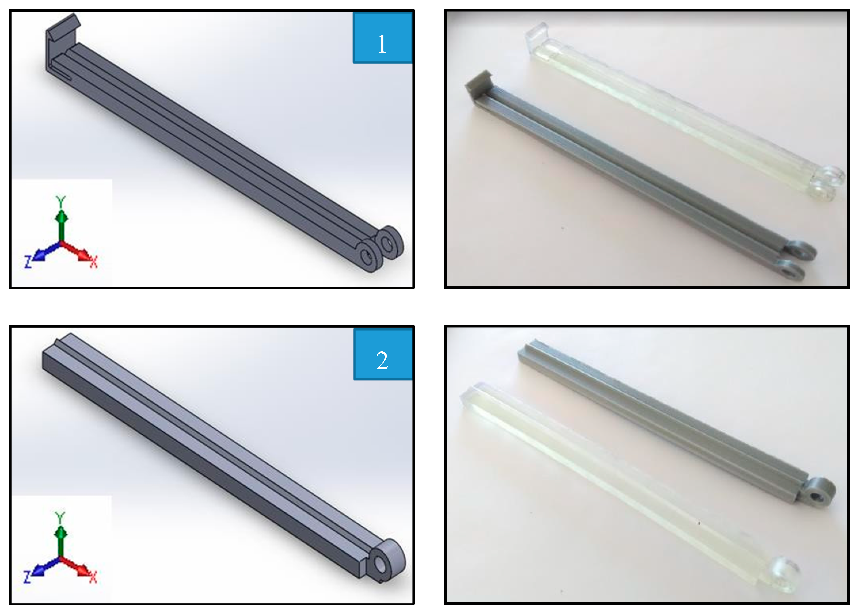
Figure 3.
Outline of features which are challenging to injunction mold.
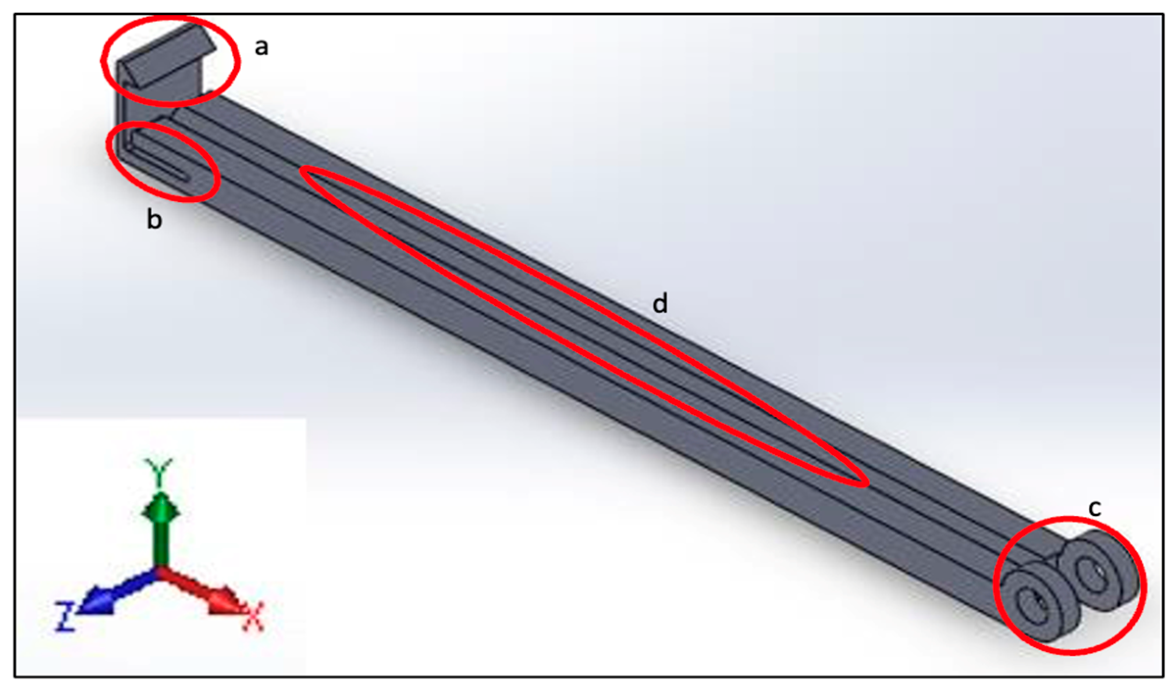
Figure 4.
Geometric error for circularity deviation in one hole feature of Part 1, showing a localized printing defect.
Figure 4.
Geometric error for circularity deviation in one hole feature of Part 1, showing a localized printing defect.
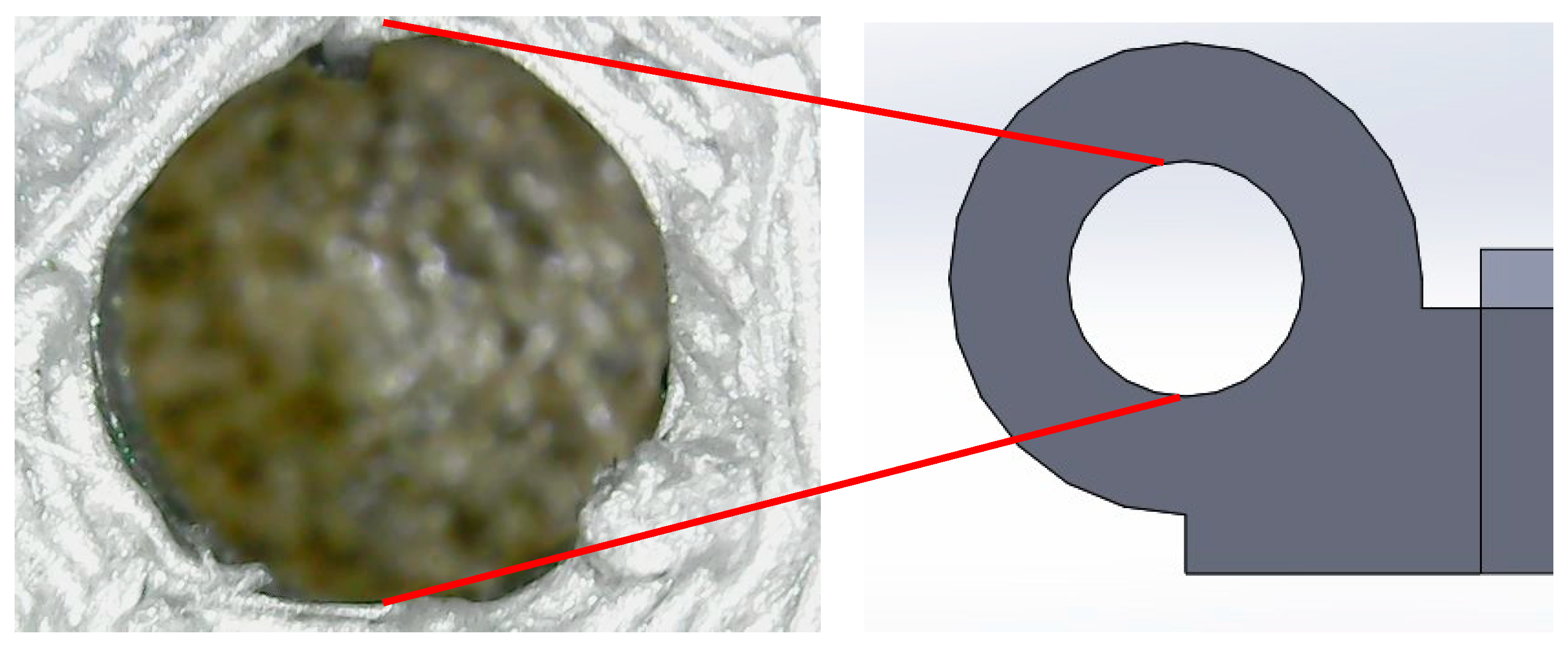
Figure 5.
Surface defect showing adhesion artifact caused by residual brim material that remains on Part 1’s surface after removal.
Figure 5.
Surface defect showing adhesion artifact caused by residual brim material that remains on Part 1’s surface after removal.
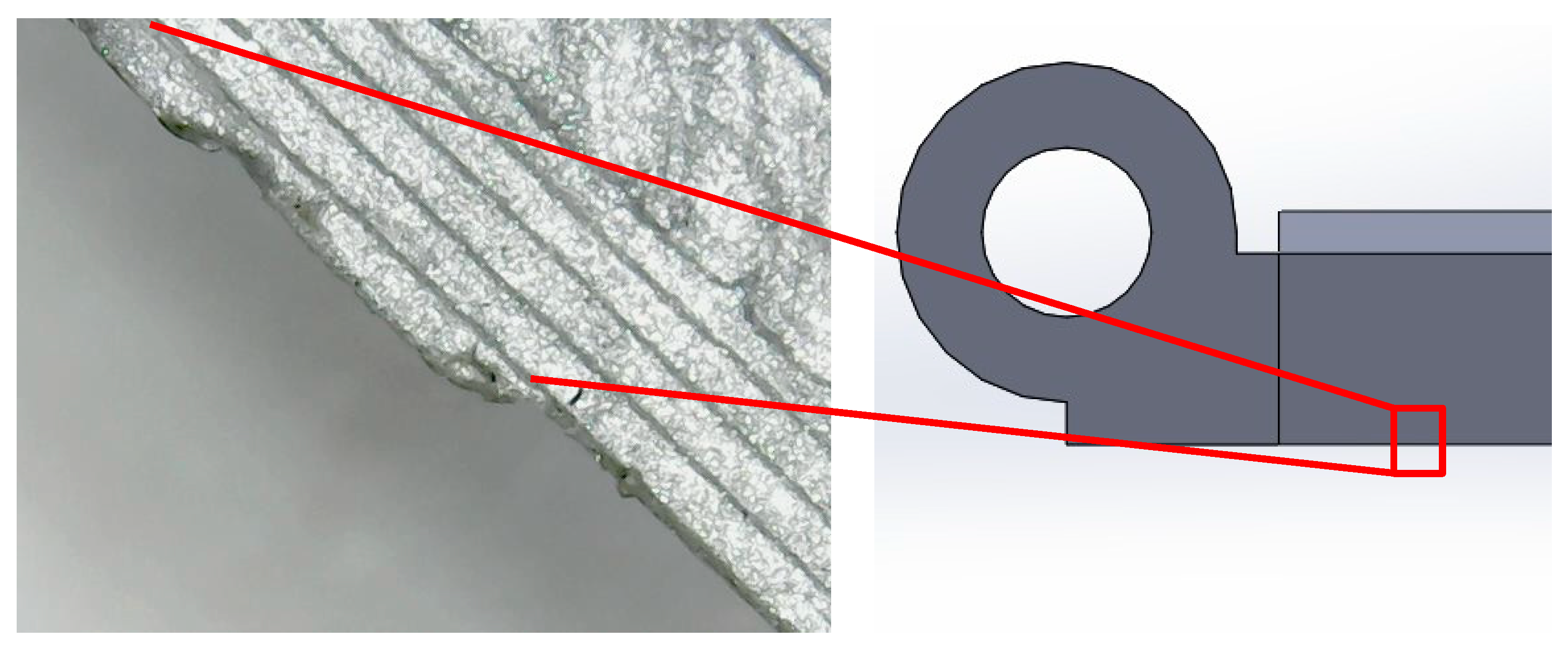
Figure 6.
Internal defect of Voids observed in Part 1 due to rasterization issues, most likely caused by insufficient infill overlap during slicing.
Figure 6.
Internal defect of Voids observed in Part 1 due to rasterization issues, most likely caused by insufficient infill overlap during slicing.
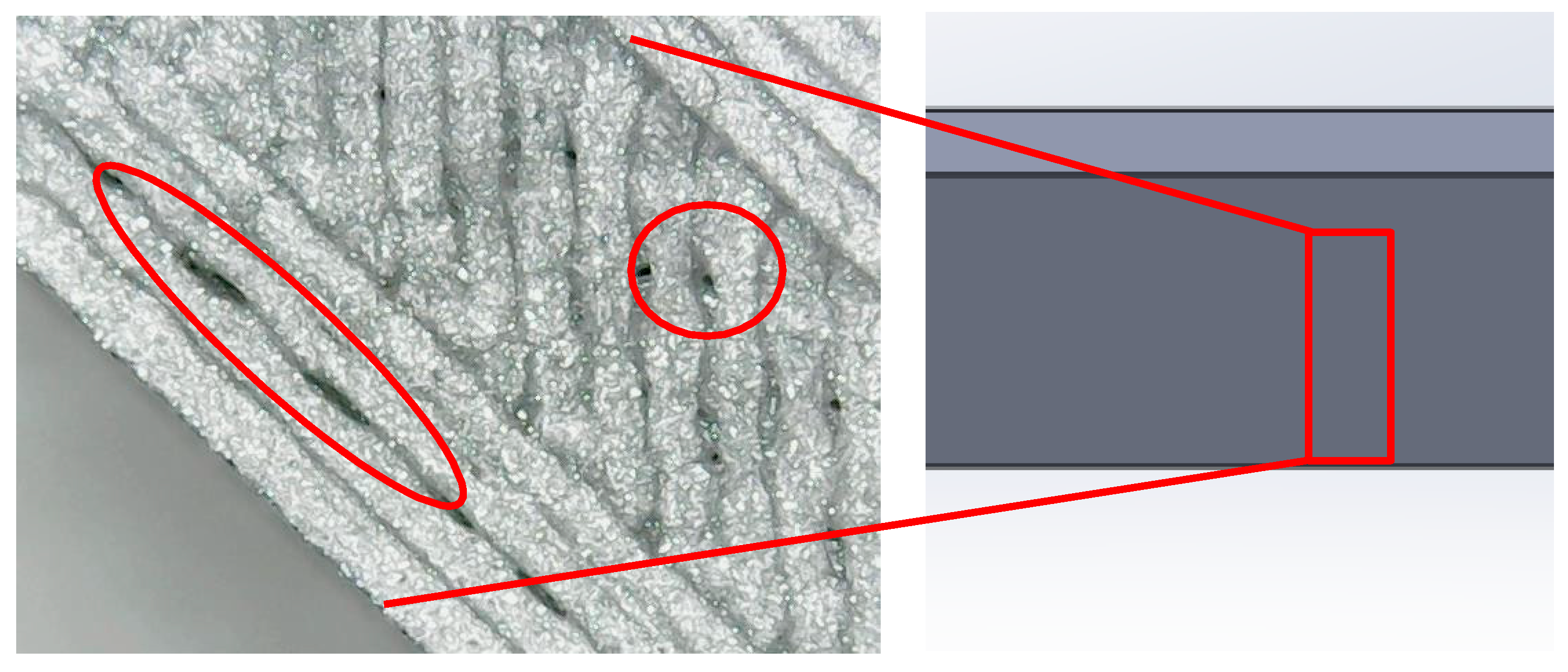
Figure 7.
Surface defect in Part 2: (a) damage to part geometry during brim removal. (b) Rough surface near the inner hole cavity as a result of localized support insufficiency.
Figure 7.
Surface defect in Part 2: (a) damage to part geometry during brim removal. (b) Rough surface near the inner hole cavity as a result of localized support insufficiency.
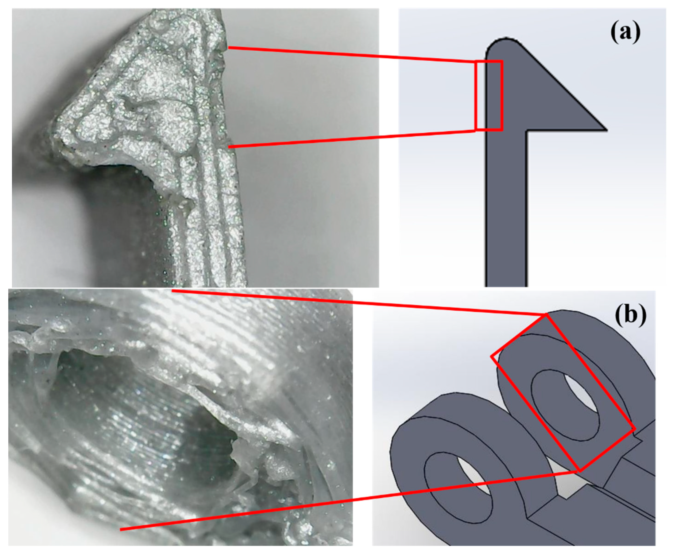
Figure 8.
Qualitative surface defects in the SLA-printed part : (a) Rough surface finish caused by support touchpoint residue; (b) tool impact creating a cavity during support removal; (c) local sagging between widely spaced supports resulting in part distortion; and (d) (e) edge chipping introduced during support structure detachment.
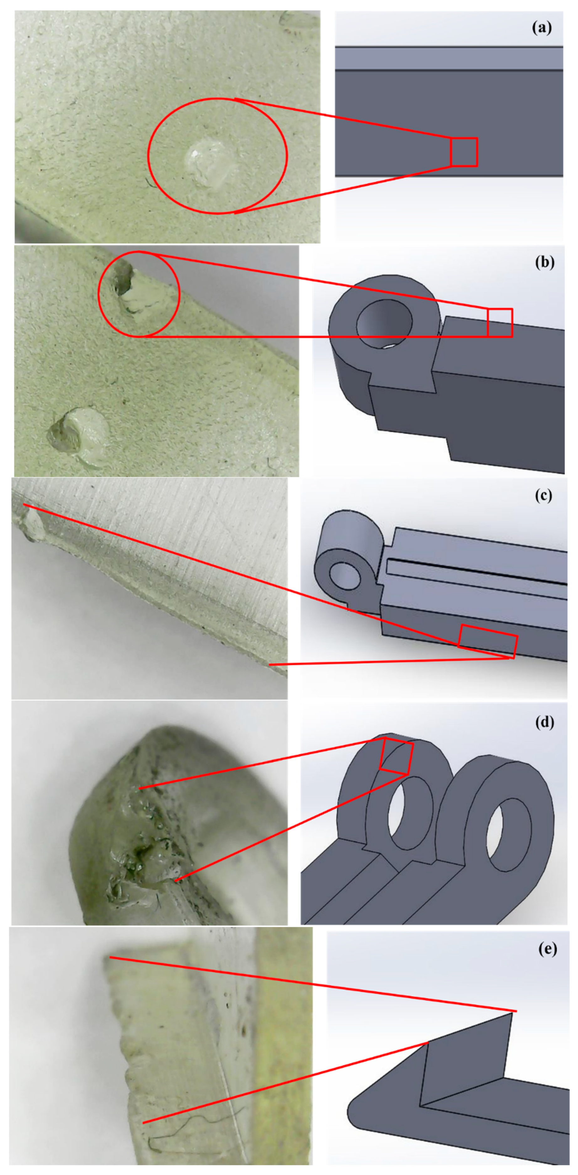
Figure 9.
CAD drawing of critical features affecting the snap-fit assembly’s overall shape and functionality used for dimensional accuracy measurements on Part1 include (a) the snap-hook beam’s thickness, (b) the snap-hook’s overhang, (c) the space between the pivots, and (d) the snap-hook entrance angle; on Part 2 include (e) the pivot length.
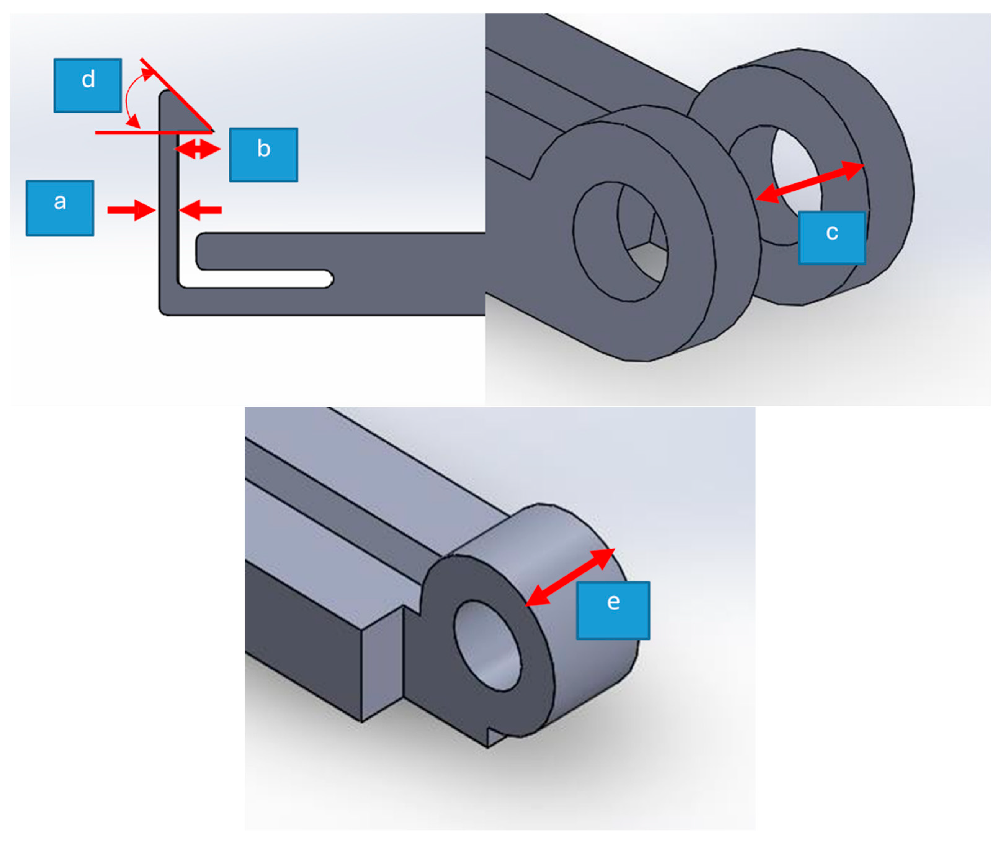
Figure 10.
Plot of measured dimensional values versus measurement sequence number for critical features: Part 1 dimensions (a) and (c) measured using vernier calipers, and Part 2 dimension (e) measured using a micrometer.
Figure 10.
Plot of measured dimensional values versus measurement sequence number for critical features: Part 1 dimensions (a) and (c) measured using vernier calipers, and Part 2 dimension (e) measured using a micrometer.
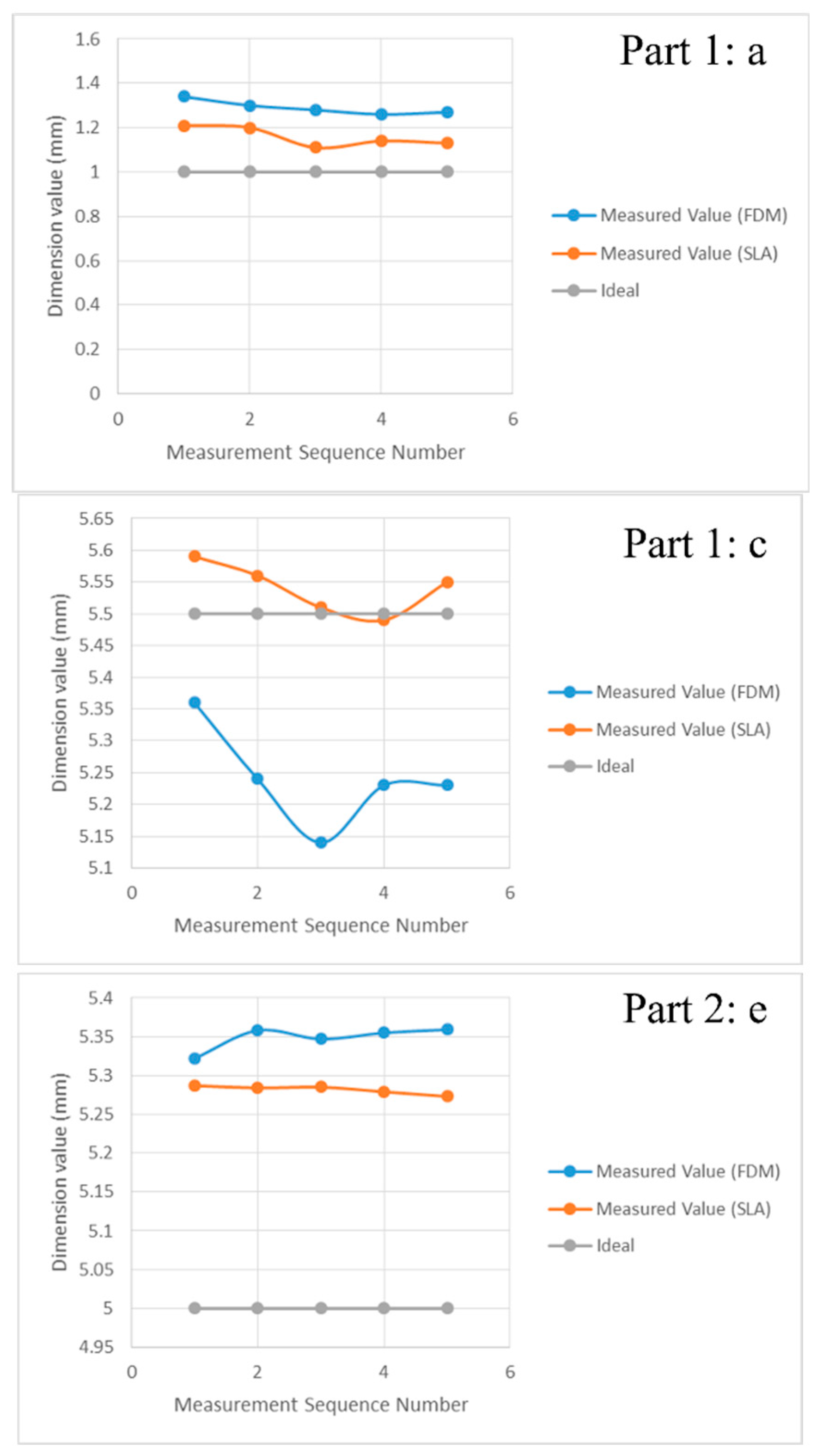
Figure 11.
Comparative dimensional deviations in thickness and pivot gap for FDM and SLA printed snap-fit assemblies.
Figure 11.
Comparative dimensional deviations in thickness and pivot gap for FDM and SLA printed snap-fit assemblies.
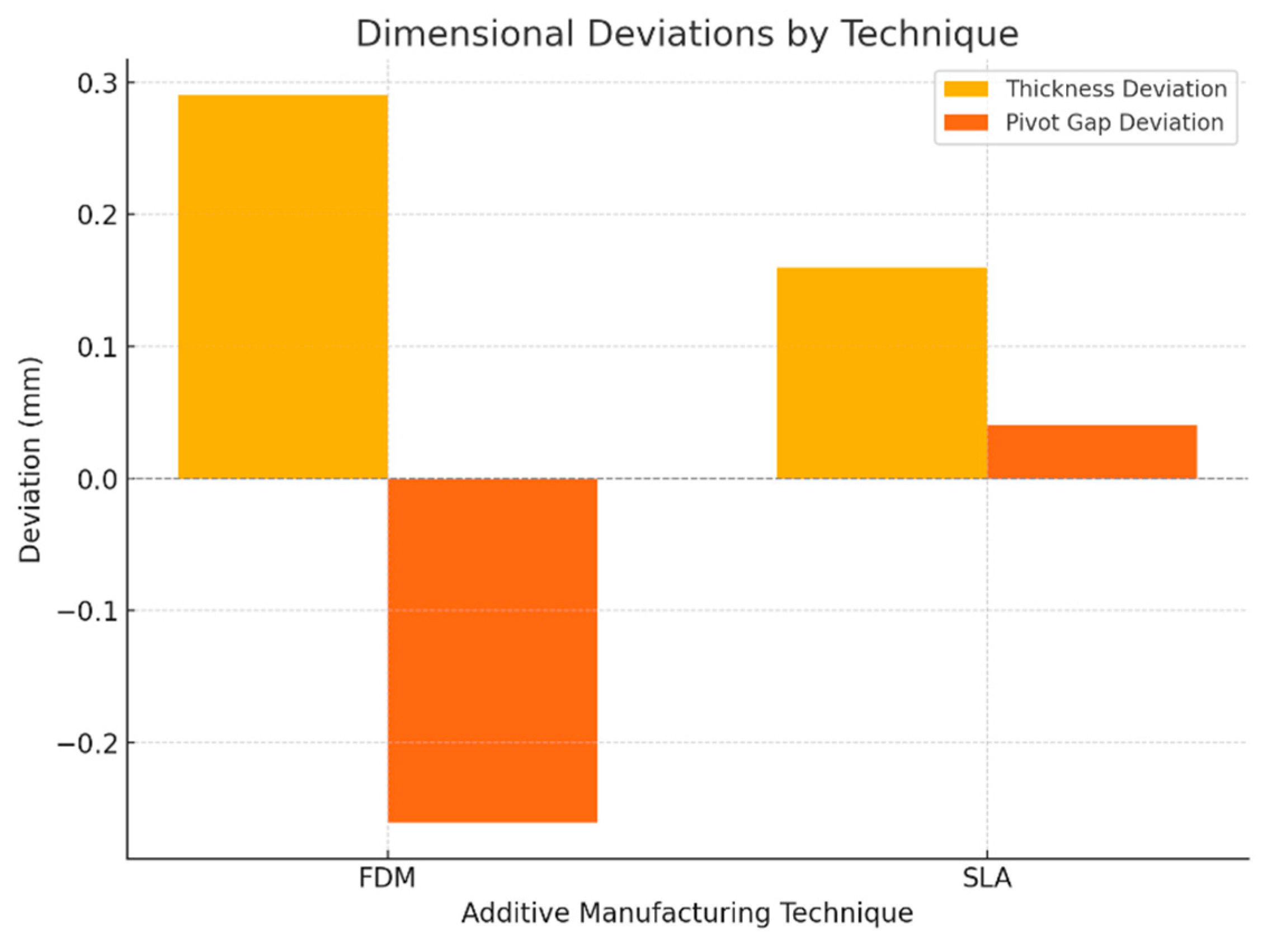
Figure 12.
Snap-fit part orientation chosen for both SLA and FDM.
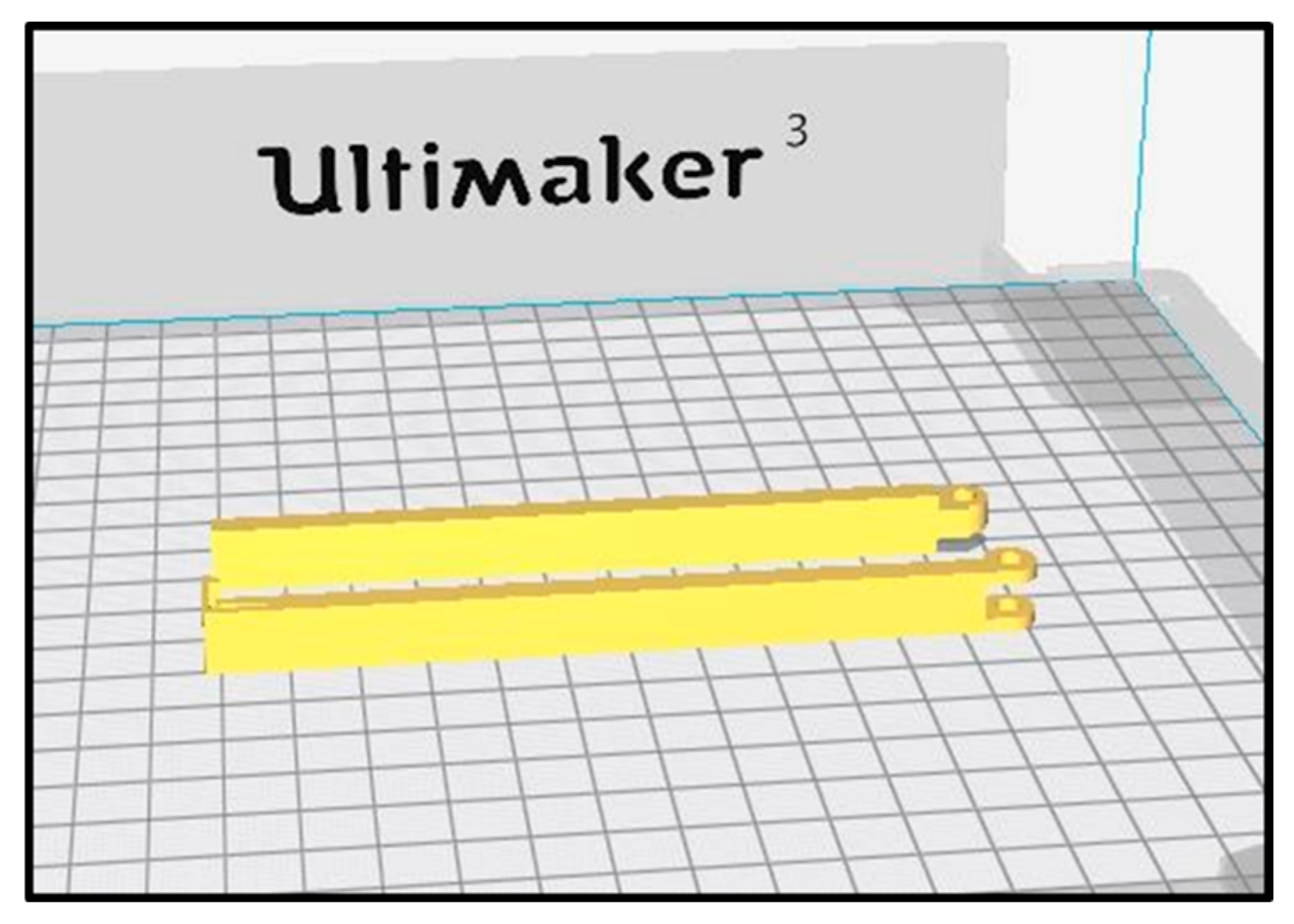
Figure 13.
Support material configuration in FDM printing (a) Support material arrangement (b) Low support density in critical area.
Figure 13.
Support material configuration in FDM printing (a) Support material arrangement (b) Low support density in critical area.
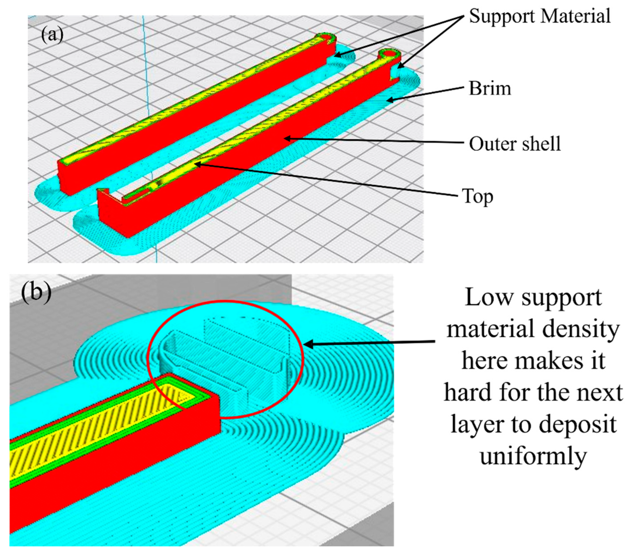
Figure 14.
Print Microstructure Comparison (a) SLA (b) FDM process (The black line in the FDM microstructure is a strand of hair kept for purpose of comparison of scale.).
Figure 14.
Print Microstructure Comparison (a) SLA (b) FDM process (The black line in the FDM microstructure is a strand of hair kept for purpose of comparison of scale.).
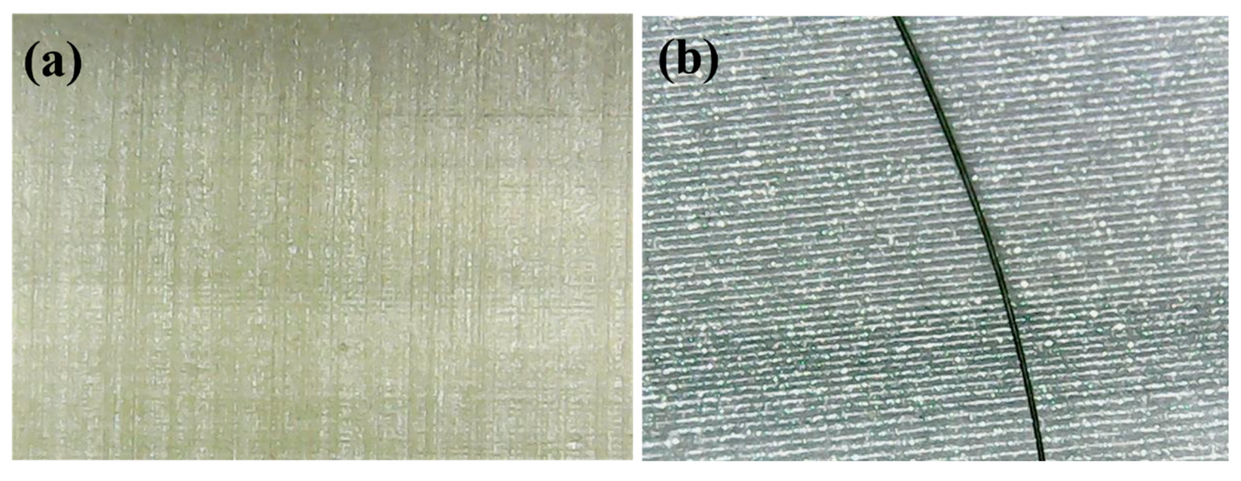
Figure 15.
Failed prints observed during fabrication: (a) Non-uniform filament extrusion (b) Under-extrusion of material (Layers missing) from the Makerbot printer (c) SLA print failure feature parts fusion near the hinge.
Figure 15.
Failed prints observed during fabrication: (a) Non-uniform filament extrusion (b) Under-extrusion of material (Layers missing) from the Makerbot printer (c) SLA print failure feature parts fusion near the hinge.
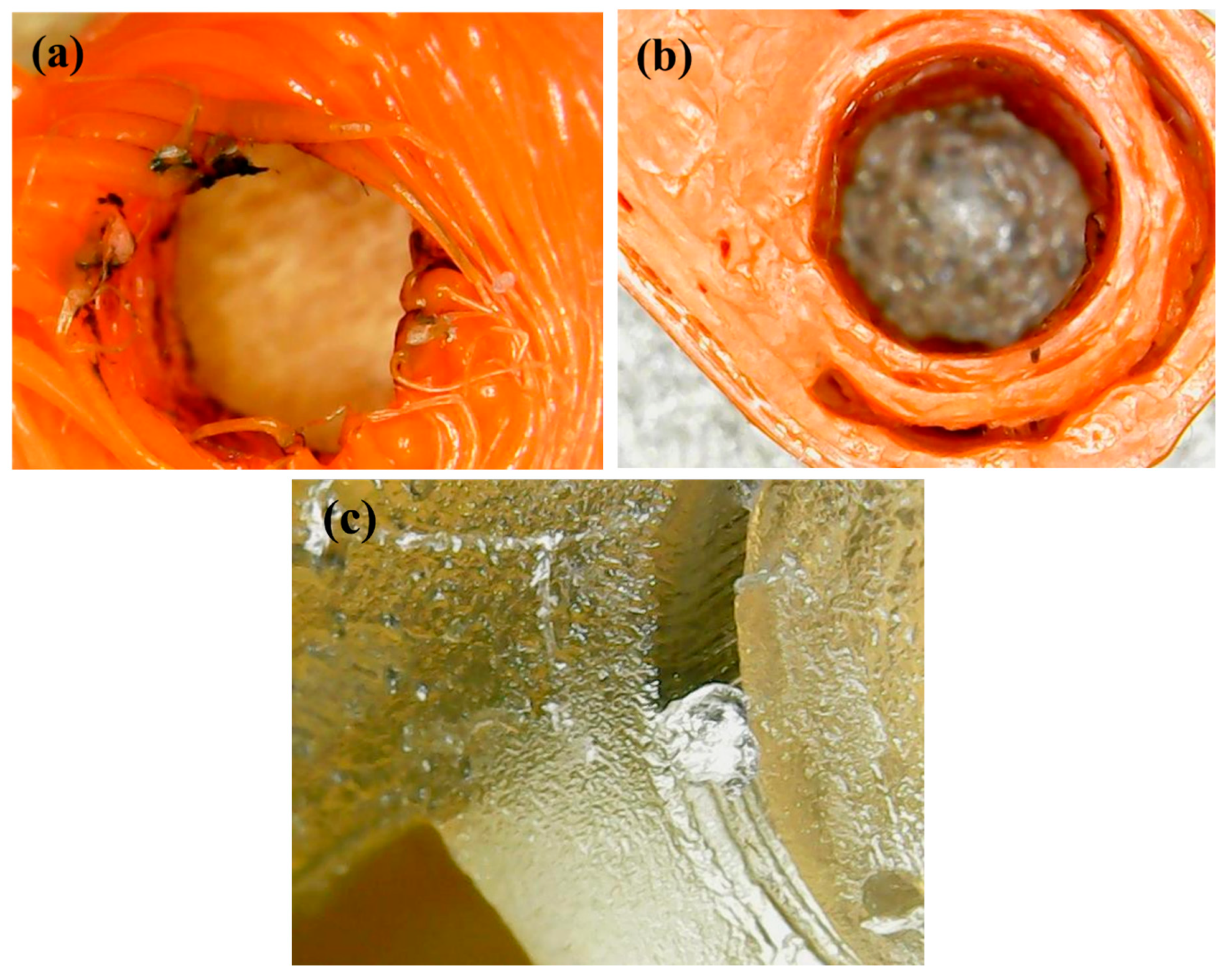
Figure 16.
Printing time vs Layer thickness for snap fit joint using FDM process.
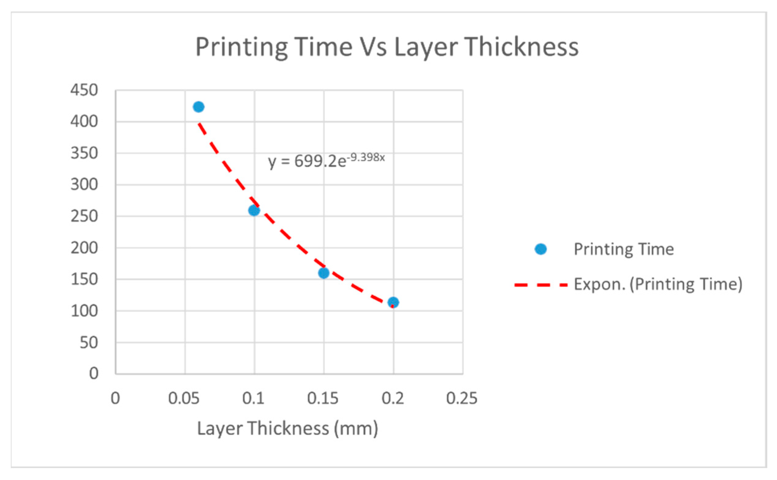
Figure 17.
Visualization of wraping induced by non-uniform part thickness in FDM.
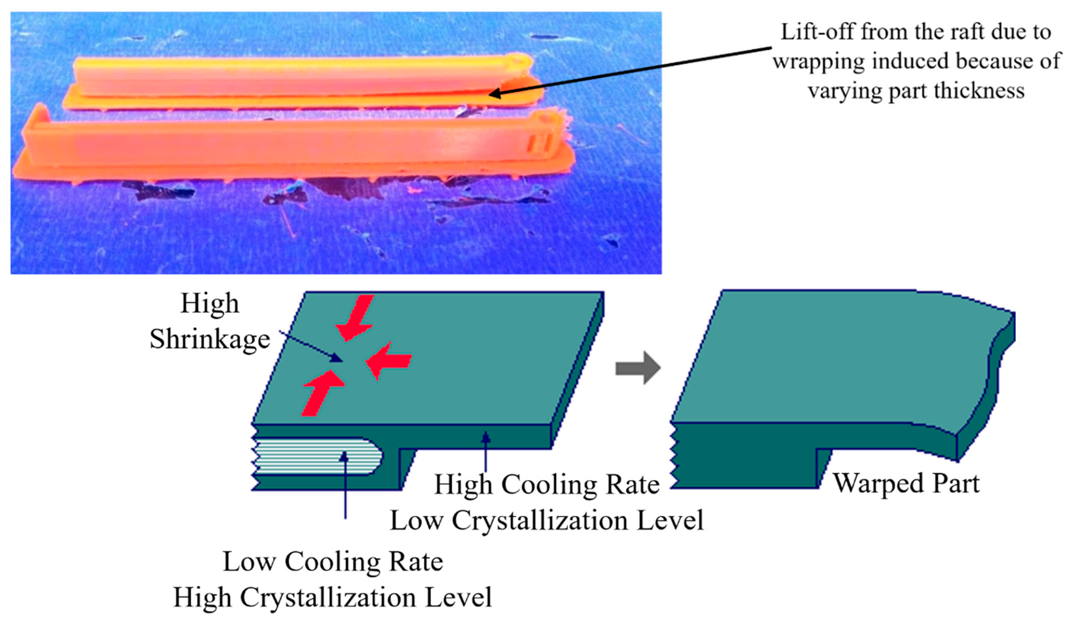
Figure 18.
Decision matrix comparing FDM and SLA across dimensional, mechanical, and operational parameters for snap-fit part manufacturing.
Figure 18.
Decision matrix comparing FDM and SLA across dimensional, mechanical, and operational parameters for snap-fit part manufacturing.
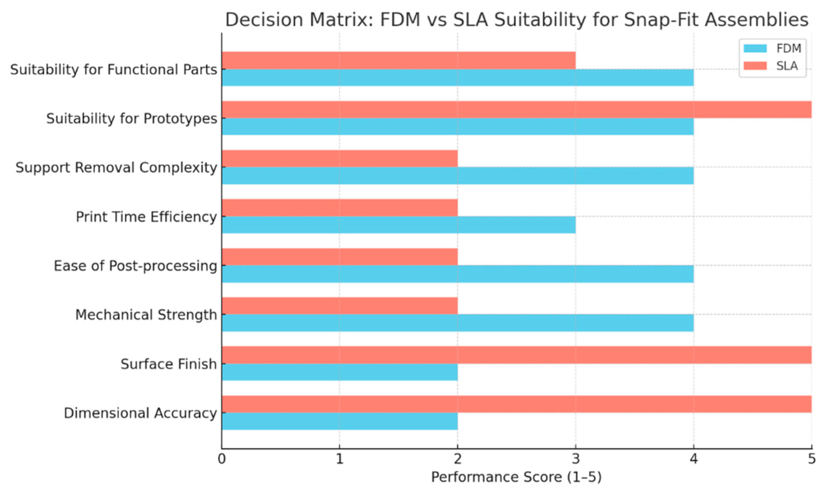
Table 2.
Summary of dimensional performance, surface quality, and post-processing challenges for FDM and SLA.
Table 2.
Summary of dimensional performance, surface quality, and post-processing challenges for FDM and SLA.
| Parameter | FDM | SLA |
|---|---|---|
| Thickness Deviation (mm) | 0.29 | 0.16 |
| Pivot Gap Deviation (mm) | -0.26 | 0.04 |
| Surface Defects | Brim marks, voids, sagging | Support scars, chipping, sagging |
| Support Removal Complexity | Low | High |
| Post-Processing Sensitivity | Moderate | High |
Disclaimer/Publisher’s Note: The statements, opinions and data contained in all publications are solely those of the individual author(s) and contributor(s) and not of MDPI and/or the editor(s). MDPI and/or the editor(s) disclaim responsibility for any injury to people or property resulting from any ideas, methods, instructions or products referred to in the content. |
© 2025 by the authors. Licensee MDPI, Basel, Switzerland. This article is an open access article distributed under the terms and conditions of the Creative Commons Attribution (CC BY) license (http://creativecommons.org/licenses/by/4.0/).
Copyright: This open access article is published under a Creative Commons CC BY 4.0 license, which permit the free download, distribution, and reuse, provided that the author and preprint are cited in any reuse.


