
Submitted:
28 May 2025
Posted:
29 May 2025
You are already at the latest version
Abstract
This study proposes a systematic solution to the motion planning challenges in dual-robot collaborative grinding and polishing systems, with its effectiveness experimentally validated. By establishing a dual-robot pose constraint model, this study innovatively integrates the “handshake” method with the seven-point calibration approach, achieving enhanced spatial mapping accuracy between the base coordinate system and tool coordinate system. Based on the modified Denavit-Hartenberg (DH) method, this study establishes kinematic modeling for EPSON C4-A901S robots on the MATLAB platform. By integrating calibration parameters, a dual-robot collaborative grinding model is constructed, with its reliability thoroughly verified through comprehensive simulations. An experimental platform integrating dual EPSON C4-series robots with grinding devices, clamping fixtures, and drive systems was established. Three-dimensional trajectory tracking tests demonstrated a positioning error of less than 2.5 mm, conclusively validating the model’s accuracy and practical applicability.
Keywords:
Dual robots
; Matlab simulation
; Calibration
; Cooperative relative motion
1. Introduction
With the rapid development of modern manufacturing technology, three-dimensional curved surface workpieces have been increasingly and widely applied in such fields as automobiles, aerospace, additive manufacturing, and abrasive tool manufacturing. As a key link to achieve high-precision surface processing, the grinding and polishing technology has put forward higher requirements for production efficiency and product quality. For a long time, in the majority of situations, this type of work has relied on manual operation. However, owing to the adverse working environment, the high-intensity workload, and the escalating precision requirements, not only has it led to substantial labor costs, but quality problems have also frequently arisen. Consequently, it is an inescapable trend that automated [1,2,3] grinding technology is progressively replacing traditional manual work.
In the current domain of grinding and polishing, the application of robots predominantly centers around single-robot grinding [4,5]. Nevertheless, as industrial products are becoming more and more complex and diversified, and the forms of complex machined parts are constantly changing, the single-robot grinding system encounters a great many challenges in respect of the grinding coverage rate. Owing to the constraints on its motion and operation, it is arduous to comprehensively and efficiently cover all the sections of complex workpieces requiring grinding. The dual-robot collaborative technology offers a novel solution to this problem. In this technical solution, the system employs a dual-robot collaboration model. The master robot secures the workpiece to be processed via the flange, while the slave robot holds the grinding tool through the flange and executes the grinding and polishing operations. Specifically, the robot tasked with fixing the workpiece possesses the kinematic ability of six degrees of freedom. It is capable of dynamically adjusting its pose during the grinding operation in accordance with the demands of diverse grinding tasks and the intricate shapes of the workpieces, thereby attaining a higher level of precision and flexibility. This design is capable of ensuring that the grinding area is comprehensively covered, effectively resolving the technical problem that a single robot usually has difficulties in achieving full coverage when handling workpieces with complex shapes. Currently, in comparison with the research accomplishments in numerous fields both domestically and internationally, the studies regarding the collaborative motion of dual robots [6,7,8,9] and the calibration of dual robots remain relatively scarce. Qin et al. [10] proposed a calibration method combining dual quaternion closed-form solutions with an iterative Levenberg-Marquardt (LM) algorithm-based approach for simultaneously calibrating hand-eye, flange-tool, and inter-robot relationships in dual-robot collaborative systems. Wang et al. [11] addressed the kinematic calibration problem of robotic hand-eye systems by proposing a separable calibration framework based on dual quaternions. Through theoretical derivation and experimental validation, they conducted an in-depth analysis of the comparative advantages, limitations, and applicable conditions between simultaneous and separable calibration methods. Hua et al. [12] proposed a hand-eye calibration algorithm integrating convex relaxation-based global optimization with dual quaternions, which enhances robotic hand-eye coordination accuracy to meet the high-precision positioning requirements for switchgear operations.
In this study, the master-slave control approach is employed. The EPSON C4-A901S robot is designated as the master robot for gripping the workpiece, while the EPSON C4-A601S robot is selected as the slave robot tasked with the grinding operation. Kinematic constraints are first established based on the closed kinematic chain formed by the dual-robot system. The “handshake” method [13] and the seven-point method [14] are then employed to precisely define the spatial transformation between the base and tool coordinate systems of the dual robots, enabling system modeling in MATLAB 2022a. Subsequently, the master and slave robots are controlled to follow predefined trajectories, with comprehensive simulation analysis conducted to validate feasibility. Finally, an experimental platform integrating EPSON C4 series robots, a grinding module, a clamping unit, and a drive system is constructed. Coordinated motion experiments are performed on the dual-robot collaborative grinding system, verifying both the reliability of the proposed approach and the accuracy of the simulation model.
2. Kinematic Analysis of Dual-Robot Systems
In this study, an EPSON C4 series robotic system is employed, where the EPSON C4-A601S—selected for its high joint motion velocity and positioning accuracy—is equipped with a grinding module to function as the grinding robot, while the EPSON C4-A901 serves as the workpiece-holding robot. Figure 1 illustrates the coordinate system relationship within the dual-robot grinding and polishing system. In the figure, [Ri] denotes the robot base coordinate system, [Ei] represents the end-effector coordinate system of the robotic arm, and [Ti] indicates the tool coordinate system of the robotic arm, where i=1 corresponds to the EPSON C4-A901S robot and i=2 refers to the EPSON C4-A601S robot, while [w] signifies the workpiece coordinate system. When the grinding tool establishes contact with the workpiece, the dual-robot system forms a closed kinematic chain. Based on the master-slave control strategy for system decoupling, the constraint equations of the system can be derived as follows:
Wherein: R₁Tw represents the transformation matrix from the workpiece coordinate system to the master robot’s base coordinate system. Upon specification of grinding task requirements and determination of the tool-path trajectory, this transformation matrix becomes fully defined and serves as a known parameter in the system; E1TT1 and E2TT2 denote the transformation matrices from the gripping tool to the master robot and from the grinding tool to the slave robot, respectively. While both matrices are structurally defined by the mechanical assembly, E2TT2 must be calibrated owing to the unique properties of the grinding tool, resulting in a constant matrix post-calibration. The homogeneous transformation matrix R1TR2 defines the spatial relationship between the base frames of both robotic systems, which is determined through calibration procedures and remains invariant during operation. The homogeneous transformation matrix T1Tw defines the spatial relationship between the workpiece frame and the gripping tool frame. This matrix is structurally determined by the mechanical assembly configuration, where the workpiece maintains a fixed pose relative to the gripping tool, resulting in a time-invariant transformation. The homogeneous transformation matrix T2Tw defines the dynamic spatial relationship between the workpiece frame and the grinding device frame. As the grinding tool must maintain persistent contact with the target point throughout the process, this matrix becomes path-dependent and exhibits time-varying characteristics [15].
2.1. Dual-Robot Base Frame Calibration
Kinematic analysis of the dual-robot system indicates that calibration of R1TR2 is essential for establishing accurate inter-robot spatial relationships. Since this relative pose relationship serves as the fundamental basis for dual-robot collaborative operation, its precise measurement is imperative. The calibration of dual-robot base frames aims to determine the transformation matrix between coordinate system R1 and R2. This study employs a calibration method in which two EPSON robots are each equipped with a calibration needle at their end-effectors. The calibration procedure involves controlling the robots to bring their needle tips into contact at four spatially distinct positions, with the critical condition that these four contact points must not lie on the same plane. Based on the coordinate relationships obtained from these non-coplanar contact points, the calibration matrix between the two robot systems is then mathematically determined. This experimental method enables direct determination of the coordinate transformation relationship between the two robotic base frames without requiring auxiliary measurement tools.
The calibration procedure is conducted as follows:
- (1)
- Coordinate system definition and notation specification: The world coordinate system, base frames (R1 and R2 for Robot 1 and Robot 2 respectively), and tool frames (T1, T2) are explicitly defined. With calibration needles mounted on each robot’s end-effector, both manipulators are controlled to establish four non-coplanar contact points (P₁-P₄) within their shared workspace. The corresponding coordinates of each contact point are recorded in both robot base frames as R1Pk and R2Pk (k=1,2,3,4).
- (2)
- Rotation matrix computation: Assuming the world coordinate system coincides with Robot 1’s base frame, we obtain:
Substituting the coordinates of the four contact points into the above equations, subtracting point coordinates and reformulating them in matrix form yields:
To ensure the solvability of R1RR2, the selected four points must be non-coplanar (the determinant of the matrix on the right-hand side of the equation must be non-zero), from which the rotation matrix is derived as follows:
- (3)
- Compute the translation matrix: Substituting the rotation matrix R1RR2 into:
- (4)
- Orthonormalization of the rotation matrix: Due to computational errors, the derived rotation matrix R1RR2 may violate orthonormality constraints. To reconcile the discrepancies between matrices while preserving geometric validity, we optimize the solution using the Frobenius norm criterion. The specific formulation is given as follows:
Define the objective function as:
Constraints:
The optimized orthonormalized rotation matrix is obtained when the objective function J reaches its minimum.
Base coordinate system calibration experiment:
The calibration experimental platform consists of an RC700-A controller with host computer, two robotic manipulators, and a calibration probe, as illustrated in Figure 2. Following the experimental procedure, a dual-robot base frame calibration was conducted, with the coordinate data of key points for both the master and slave robots recorded in Table 1 and Table 2 respectively.
The rotation matrix R1RR2 is derived from Equation (5).
The translation matrix R1PR2 is derived from Equation (6).
After orthonormalization, the transformation matrix between the base frames of the two robots is obtained as:
2.2. TCP Calibration
This paper adopts the seven-point method for Tool Center Point (TCP) calibration.
The calibration procedure is as follows:
- (1)
- Determine calibration points: A calibration needle is fixed on the optical platform, with its tip position designated as P. Control the robot to position the tool end-effector at point P with four distinct orientations, as illustrated in Figure 3, while recording its pose relative to the base coordinate frame.
- (2)
- Formulate the system of equations: Applying coordinate transformation principles yields the relevant equations. Since the tool end-effector reaches the same position four times, simultaneous elimination of point P coordinates gives matrix:
Where matrix A is composed of differences between rotation matrices of the flange end coordinate system under different orientations, matrix B consists of corresponding positional differences, and X represents the tool center point (TCP) position in the end-effector coordinate system (E2PT).
- (3)
- Solve using least squares method: Obtain E2PT2 by applying the least squares principle:
- (4)
- Initial Position Adjustment and Recording: Move the robot near the origin point, adjust the joints to align the tool coordinate system’s X and Z axes parallel to the corresponding axes of the base coordinate system, then record the data parameters (for the 5th calibration point).
- (5)
- Motion Position Recording: Maintaining the current orientation, move from Point 5 along the X and Y axes of the base coordinate system by specified distances respectively, then record the parameters for Points 6 and 7 as illustrated in Figure 4.
- (6)
- Direction Vector Determination:
- (7)
- Transformation Matrix Computation: Orthonormalize PX, PY, PZ and substitute to obtain:
Combining the obtained E2PT2, we derive E2TT2:
TCP Calibration Experiment:
By operating the Epson C4-A601S robot through its controller, the tool end-effector was repeatedly positioned at the same target point in 4 distinct spatial orientations (as illustrated in Figure 5). The end-effector pose data for each repetition were recorded. The experimental dataset has been compiled in Table 3.
The position matrix E2PT2 is obtained according to Equation (14):
Furthermore, since the Y-axis, Z-axis, and X-axis of the tool coordinate system are parallel to the X-axis, Y-axis, and Z-axis of the base coordinate system respectively, PX and PY represent the directional vectors of the Y-axis and Z-axis in the tool coordinate system. The robot was controlled to move 50mm along the X-axis and 50mm along the Y-axis of the base coordinate system, with the data shown in Table 4.
The matrices R2RT2 and E2TT2 are computed using (17) and (18).
3. Master Robot Modeling and Verification
3.1. Robot Coordinate Frame
The EPSON C4-A901S robot is a serial articulated robot with six revolute joints. The modified Denavit-Hartenberg (D-H) parameter method was employed to establish the robot link coordinate system, as illustrated in Figure 6. Furthermore, the MDH parameters of the EPSON C4-A901S robot were obtained and are presented in Table 5. The EPSON C4-A601S robot differs in the MDH table only by the parameters a₃=250 and d₄=-250.
β denotes the minor angular deflection between nominally parallel axes; βi represents the joint offset of the i-th joint; θi is the angle between two adjacent links; ai indicates the link length; αi specifies the angle between two normal; and dᵢ defines the distance between two normal.
3.2. Simulation and Verification of Robot MATLAB Model
Based on the MDH parameters presented in Table 5, the robotic model of EPSON C4-A901S was simulated using the Link function from MATLAB Robotics Toolbox. The simulation results of the EPSON C4-A901S robot are obtained as shown in Figure 7.
The homogeneous transformation matrix is obtained by solving the simulation model using the fkine command:
The homogeneous transformation matrix is obtained using the RC+ software provided with the EPSON robot:
The MATLAB model demonstrates good agreement with the actual robot system.
Within the constrained workspace, Figure 8(a) shows the robot motion from initial position A (0, 0, 0, 0, 0, 0) to B (pi/2, pi/6, -pi/6, pi/3, -pi/4, 0) through teach pendant programming, while Figure 8(b) presents the results obtained via EPSON RC+ software control.
By comparing the recorded position and orientation data of the robotic arm in Figure 8, it can be concluded that the MATLAB-based robot model parameters exhibit high consistency with the actual robotic system. As shown in Figure 9, the joint motion of the EPSON C4-A901S robot model demonstrates excellent smoothness over time without abrupt changes. This indicates that the established simulation model accurately characterizes the kinematic behavior of the physical system.
3.3. MATLAB-Based Modeling and Simulation of the Master Robot
For E1TT1, as illustrated in Figure 1, the gripper is connected to the end flange along the Z-axis via bolts, from which the transformation matrix T is derived through measurement.
Similarly, the transformation matrixT1Tw is obtained.
The master robot model was simulated using the tool function from the MATLAB Robotics Toolbox, as shown in Figure 10. In robotic kinematics and coordinate system definitions, the tool coordinate frame (TCF) is established as a local frame relative to the end-effector coordinate frame. Through the robot’s teach mode, the tool coordinate frame’s pose relative to the base frame is displayed, resulting in a change of the y-coordinate value from 565.0 to 805.5.
4. Collaborative Motion Simulation Analysis
A dual-robot grinding simulation platform was established using MATLAB Robotics Toolbox, with subsequent motion simulation analysis of the collaborative grinding system.
4.1. Establishment of the Dual-Robot Model
Based on the derived R1PR2 and E2TT2 transformations, a dual-robot grinding simulation model was established using MATLAB Robotics Toolbox, as illustrated in Figure 11.
4.2. Cooperative Motion Simulation of Dual Robots
Within constrained space, the cup’s edge surface is chosen for grinding; the actual workpiece is illustrated in Figure 12. Dual-arm trajectory control: The master robot performs linear spatial motion with fixed end-effector orientation, while the slave robot tracks a circular edge path on the cup within its restricted workspace.
The slave robot is positioned at the designated starting point for grinding, and its pose data is acquired to derive the transformation matrix of the workpiece relative to the base coordinate system as:
Based on the calibration results, Equations (1-1) and (1-2) are used to determine the end-effector trajectories and corresponding joint angles for both robotic arms. The simulation results obtained from these equations are shown in Figure 13 and Figure 14.
As shown in Figure 13a and Figure 14a, the joint angles of all six joints for both robots demonstrate smooth variation characteristics over time, with no observable abrupt joint motion phenomena. Furthermore, comparative analysis of Figure 13b and Figure 14b demonstrates satisfactory position tracking accuracy for both robotic manipulators. Thus, the feasibility and effectiveness of the proposed dual-robot grinding motion planning model are successfully validated.
5. Coordinated Motion Experiment
As illustrated in Figure 15, the dual-robot coordinated motion hardware platform comprises the following components: two 6-DOF industrial robots (EPSON C4-A601s and EPSON C4-A901s), an upper computer, an air compressor, two RC700-A robot controllers, a pressure sensor, gripping tools, and grinding tools.
The system’s software architecture is implemented through EPSON’s native RC+ development platform, employing SPEL+ programming language to establish Ethernet-based communication with robot controllers for real-time robotic control.
During the experimental procedure, the host computer was initially interfaced with both EPSON C4-A901S controllers via Ethernet and USB communication protocols respectively. Subsequently, the SPEL+ programming language was employed to compile motion programs for both the master and slave robots. The compiled programs were then uploaded to the respective robot controllers. Upon receiving the code, each controller executed an internal processing sequence comprising: (1) path planning generation, (2) motion trajectory calculation, (3) conversion to motor control signals, and (4) actuation of robotic joints. Finally, joint angle data and positional coordinates during operation were recorded through the execution of Call instructions.
The critical aspects of dual-robot collaborative motion are illustrated in Figure 16. During dual-robot collaborative motion, the simulated reference trajectory and actual tracking trajectory of the master-slave robot end-effectors demonstrate high consistency, as shown in Figure 17(a). This phenomenon preliminarily verifies that the dual-robot collaborative simulation model exhibits high accuracy and reliability in simulating real-world motion scenarios. To quantitatively evaluate the positional tracking accuracy of dual-robot collaborative operation, an in-depth analysis was conducted on the motion errors of the grinding tool along the X, Y, and Z axes (as shown in Figure 17(b)). Precision measurements and data processing revealed maximum motion errors of the grinding tool along the X, Y, and Z axes to be 2.158 mm, 1.81 mm, and 0.855 mm respectively, all within the 2.5 mm tolerance threshold. The observed errors primarily originate from calibration inaccuracies, deviations between theoretical and actual MDH parameters of the robots, and mechanical structural errors. These results demonstrate that the dual-robot collaborative simulation model can effectively guide practical operations, ensuring precise tracking of desired trajectories during coordinated motion while meeting stringent performance requirements for positional accuracy in collaborative tasks. This provides robust technical assurance for efficient and stable dual-robot collaborative operations.
6. Conclusions
This section is not mandatory but can be added to the manuscript if the discussion is unusually long or complex.
This study addresses the high-precision positioning challenge in dual-robot collaborative grinding and polishing by proposing an innovative, simple yet efficient calibration method that integrates the seven-point method with handshake calibration. Using a calibration needle as the reference tool, the method achieves rapid and precise positioning of dual robots, breaking through the accuracy bottleneck of system coordination in complex working scenarios.
This study establishes a system of kinematic constraint equations for dual robots based on their closed-loop motion chain configuration. Based on the process parameters and technical requirements of the grinding task, this study employs trajectory planning algorithms to generate precise grinding paths. Under the master-slave control architecture, this study first plans the ideal posture trajectory for the master robot, then determines the slave robot’s pose parameters through inverse kinematics solving based on real-time updated collaborative motion constraint equations, thereby achieving efficient coordination of dual robots in grinding operations. During system calibration, the “handshake” calibration method is employed to align the base frames of dual robots. By establishing transformation relationships between the global coordinate system and individual robot coordinate systems, base frame installation errors are effectively eliminated. A seven-point calibration method is employed to achieve precise positioning of the Tool Center Point (TCP), where coordinated measurements via the robot’s end-effector ensure high-accuracy acquisition of TCP coordinates. The integration of these two calibration methods fulfills the high-precision operational requirements of dual-robot systems. In robotic modeling, an improved Denavit-Hartenberg (D-H) parameter method was employed to establish the kinematic model of the gripper robot (EPSON C4-A901S), with experimental validation confirming the model’s effectiveness and accuracy.
Based on the aforementioned calibration results, a dual-robot collaborative grinding simulation model was developed using the MATLAB Robotics Toolbox, followed by trajectory tracking experiments. Experimental results demonstrate that the grinding model achieves position tracking accuracy within 2.5mm, with comparative analysis against physical measurements confirming the validity and reliability of the dual-robot kinematic model. This research significantly enhances the positioning accuracy of dual-robot systems and improves their adaptive recognition capability for end-effector tools, thereby establishing a robust yet straightforward technical solution for high-precision collaborative grinding of complex workpieces.
Funding
This research was funded by the Key Research and Industrialization Project of Fujian Province, China (No. 2024XQ027), the Major Project of Science and Technology of Quanzhou (No. 2022GZ8), and the Technology Innovation Team for Minnan University of Science and Technology (24XTD156).
Conflicts of Interest
The authors declare no conflict of interest.
References
- Slepicka, M.; Borrmann, A. Fabrication Information Modeling for Closed-Loop Design and Quality Improvement in Additive Manufacturing for Construction. Autom. Constr. 2024, 168, 105792. [Google Scholar] [CrossRef]
- Bozzi, A.; Graffione, S.; Jimenez, J.-F.; Sacile, R.; Zero, E. A Platoon-Based Approach for AGV Scheduling and Trajectory Planning in Fully Automated Production Systems. IEEE Trans. Ind. Inform. 2025, 21, 594–603. [Google Scholar] [CrossRef]
- Li, L.; Wang, C.; Wu, H. Trajectory Planning of Parallel Mechanism for Pouring Robot. Curr. Sci. 2019, 116, 1829–1839. [Google Scholar] [CrossRef]
- Zhao, Z.; Xiong, J.; Li, L.; Wang, H.; Lin, J.; Zhu, L.; Guo, D.; Wang, X. Fundamental Study of Surface Generation in Robot-Assisted Polishing of Optical Components. Int. J. Adv. Manuf. Technol. 2025, 137, 2221–2235. [Google Scholar] [CrossRef]
- Zeng, X.; Zhu, G.; Gao, Z.; Ji, R.; Ansari, J.; Lu, C. Surface Polishing by Industrial Robots: A Review. Int. J. Adv. Manuf. Technol. 2023, 125, 3981–4012. [Google Scholar] [CrossRef]
- Jiang, C.; Li, W.; Li, W.; Wang, D.; Zhu, L.; Xu, W.; Zhao, H.; Ding, H. A Novel Dual-Robot Accurate Calibration Method Using Convex Optimization and Lie Derivative. IEEE Trans. Robot. 2024, 40, 960–977. [Google Scholar] [CrossRef]
- Zhu, L.; Cheng, H.; Yin, X.; Zhang, K.; Liu, S.; Zhang, X. A Vision-Based Simultaneous Calibration Method for Dual-Robot Collaborative System. IEEE Trans. Ind. Inform. 2024, 20, 13396–13405. [Google Scholar] [CrossRef]
- Mao, J.; Xu, R.; Ma, X.; Hu, S.; Bao, X. Fast Calibration Method for Base Coordinates of the Dual-Robot Based on Three-Point Measurement Calibration Method. Appl. Sci. 2023, 13. [Google Scholar] [CrossRef]
- Qian, L.; Hao, L.; Cui, S.; Gao, X.; Zhao, X.; Li, Y. Research on Motion Trajectory Planning and Impedance Control for Dual-Arm Collaborative Robot Grinding Tasks. Appl. Sci. 2025, 15, 819. [Google Scholar] [CrossRef]
- Qin, Y.; Geng, P.; Lv, B.; Meng, Y.; Song, Z.; Han, J. Simultaneous Calibration of the Hand-Eye, Flange-Tool and Robot-Robot Relationship in Dual-Robot Collaboration Systems. Sensors 2022, 22, 1861. [Google Scholar] [CrossRef] [PubMed]
- Wang, X.; Song, H. Dual-Quaternion-Based Kinematic Calibration in Robotic Hand-Eye Systems: A New Separable Calibration Framework and Comparison. Appl. Math. Model. 2025, 144, 116076. [Google Scholar] [CrossRef]
- Hua, J.; Su, Y.; Xin, D.; Guo, W. A High-Precision Hand–Eye Coordination Localization Method under Convex Relaxation Optimization. Sensors 2024, 24, 3830. [Google Scholar] [CrossRef] [PubMed]
- Gan, Y.; Dai, X. Base Frame Calibration for Coordinated Industrial Robots. Robot. Auton. Syst. 2011, 59, 563–570. [Google Scholar] [CrossRef]
- Luo, H.L; Wang, L; Xiang, F.Z; Ou, Y.W; Wang, P. Calibration method of tool coordinate system based on least squares. Elec⁃ Tronic Meas. Technol. 2020, No. 2, 6–9.
- Cruz-Ortiz, D.; Chairez, I.; Poznyak, A. Adaptive Sliding-Mode Trajectory Tracking Control for State Constraint Master–Slave Manipulator Systems. ISA Trans. 2022, 127, 273–282. [Google Scholar] [CrossRef] [PubMed]
Figure 1.
Coordinated Constraint Relationships in Dual-Robot Systems.
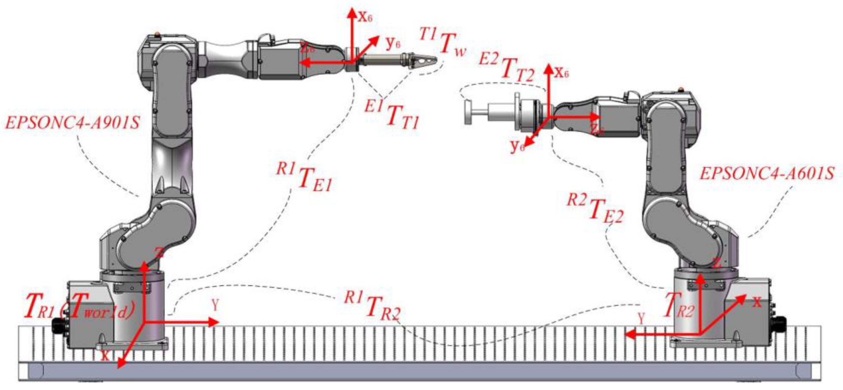
Figure 2.
Base frame calibration experimental platform.
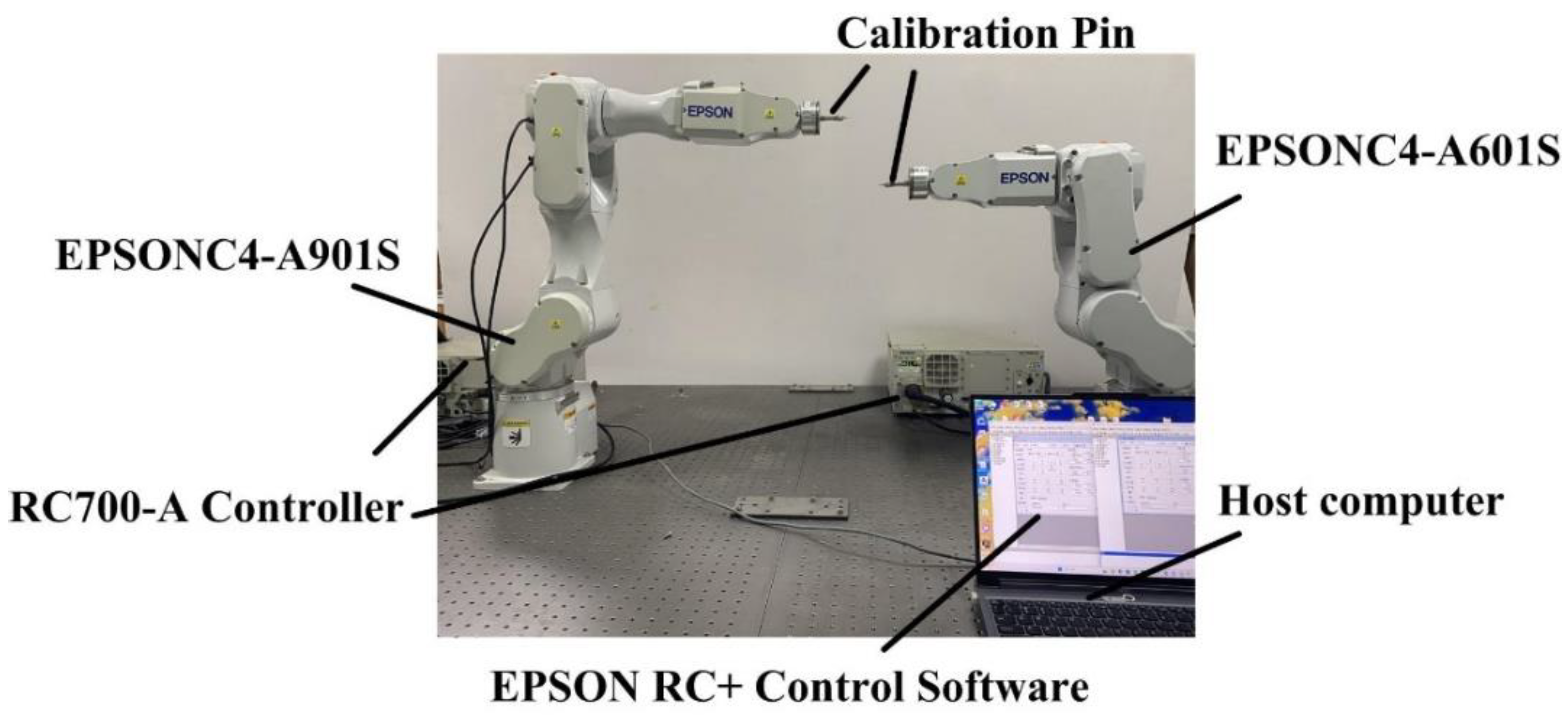
Figure 3.
Position Calibration Schematic.
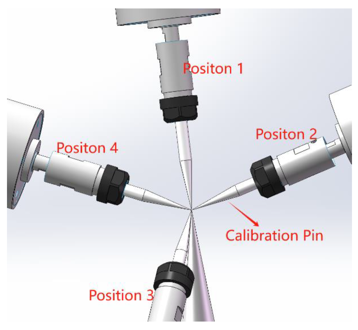
Figure 4.
Schematic Representation of Posture Calibration.

Figure 5.
TCP Calibration Experimental Diagram: a) First pose, b) Second pose, c) Third pose, d) Fourth pose.
Figure 5.
TCP Calibration Experimental Diagram: a) First pose, b) Second pose, c) Third pose, d) Fourth pose.
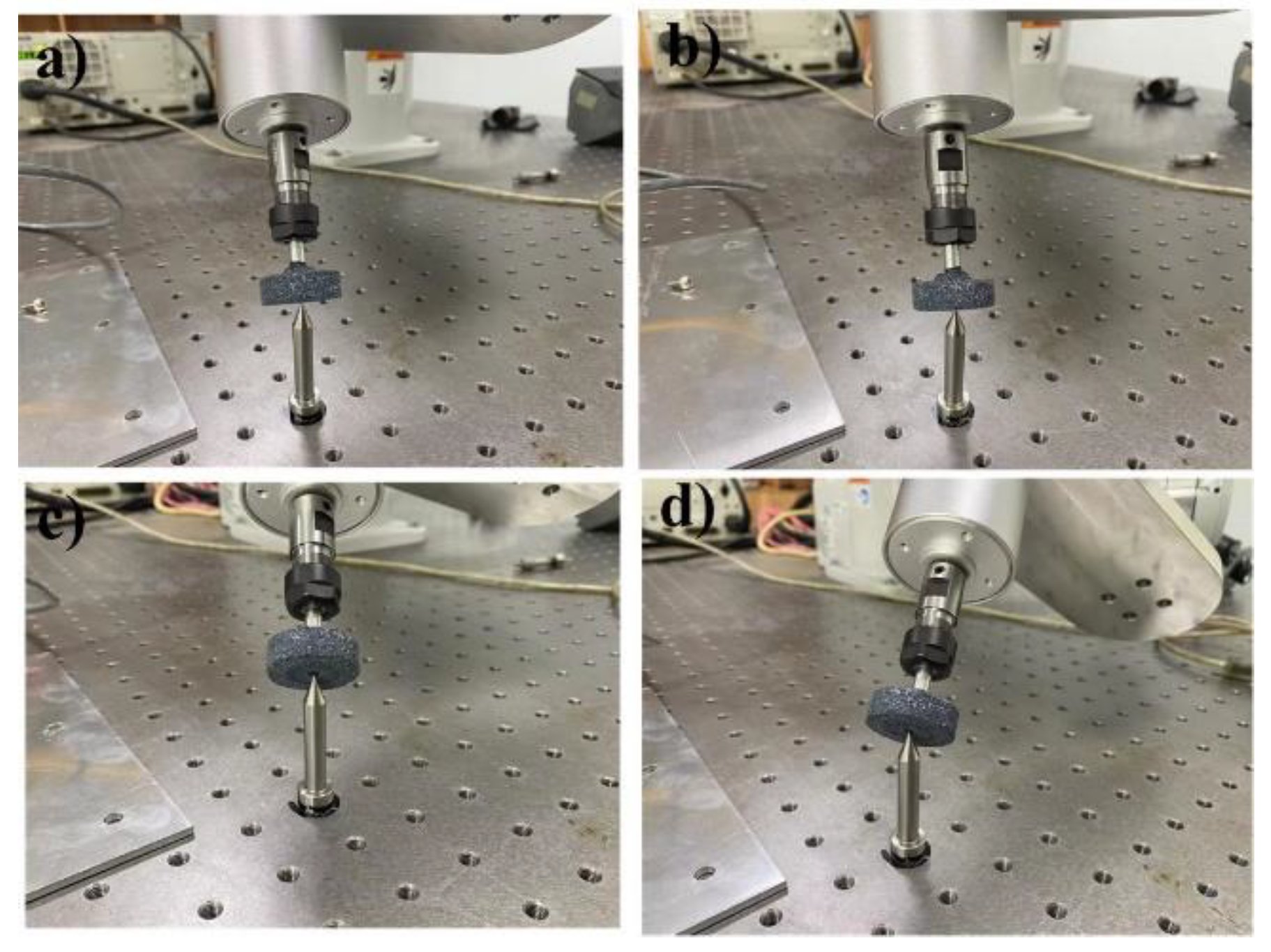
Figure 6.
Link Coordinate System Diagram for Robotics: a) EPSONC4-A601S Robot, b) EPSONC4-A901S Robot.
Figure 6.
Link Coordinate System Diagram for Robotics: a) EPSONC4-A601S Robot, b) EPSONC4-A901S Robot.
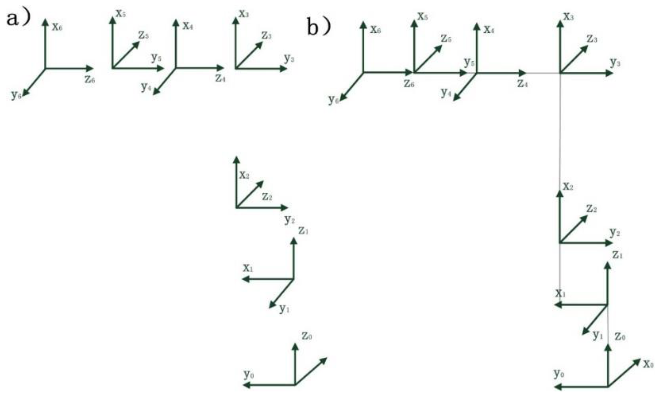
Figure 7.
EPSONC4-A901S Robot Model.
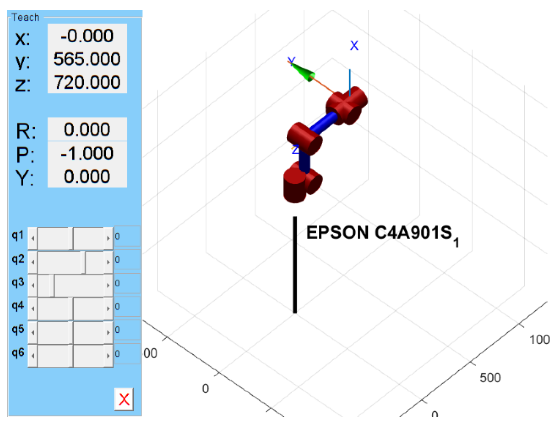
Figure 8.
Position and orientation: (a) Posture after simulated motion, (b) Posture after physical movement.
Figure 8.
Position and orientation: (a) Posture after simulated motion, (b) Posture after physical movement.
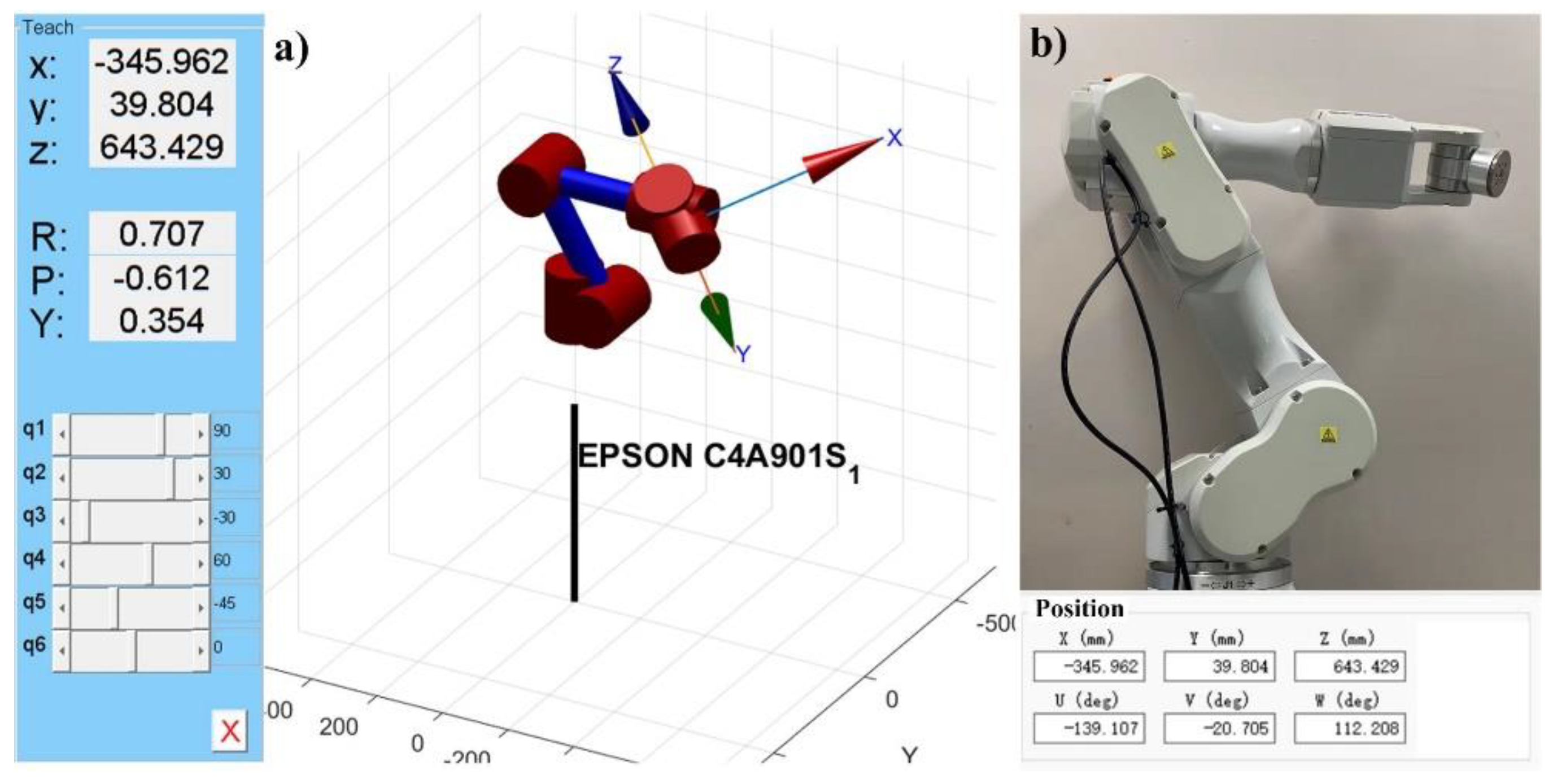
Figure 9.
Joint and Trajectory: (a) Joint angle profiles of the robot (b) End-effector trajectory of the robot.
Figure 9.
Joint and Trajectory: (a) Joint angle profiles of the robot (b) End-effector trajectory of the robot.
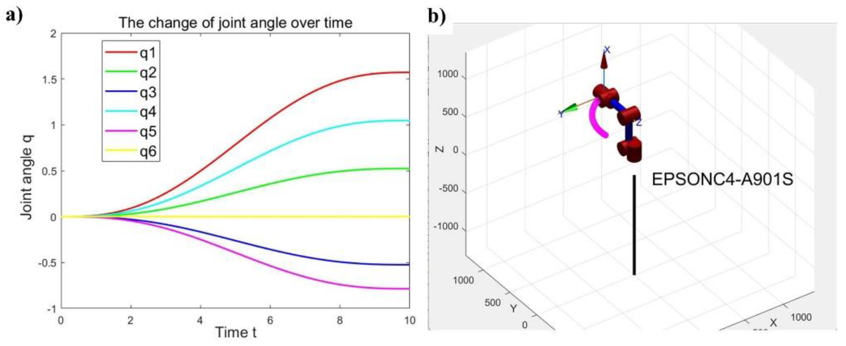
Figure 10.
Master Robot Simulation Model.
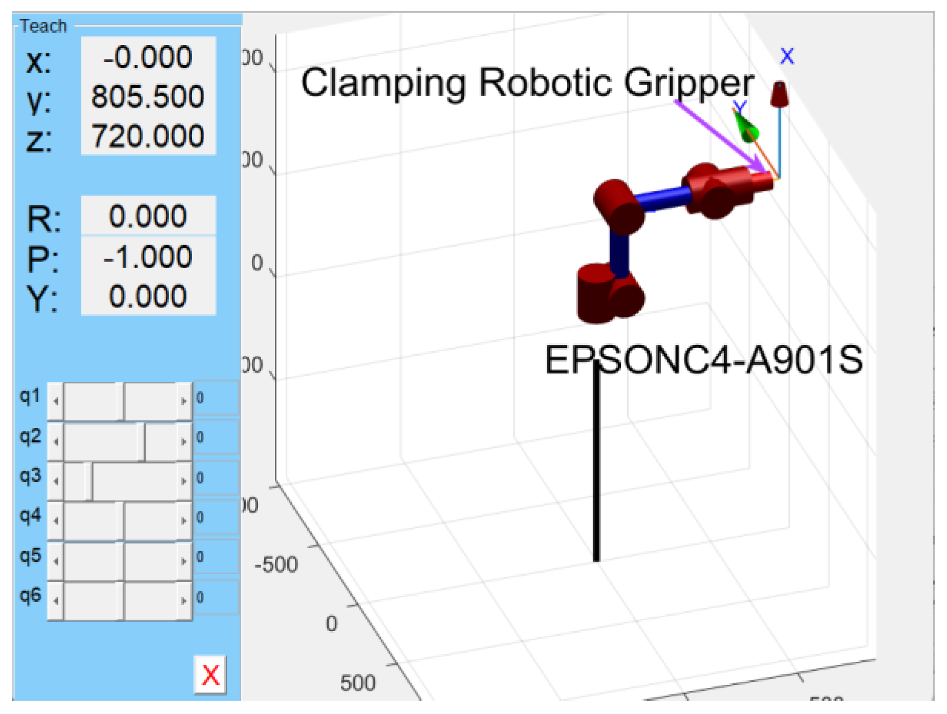
Figure 11.
Dual-Robot Grinding Simulation Model.
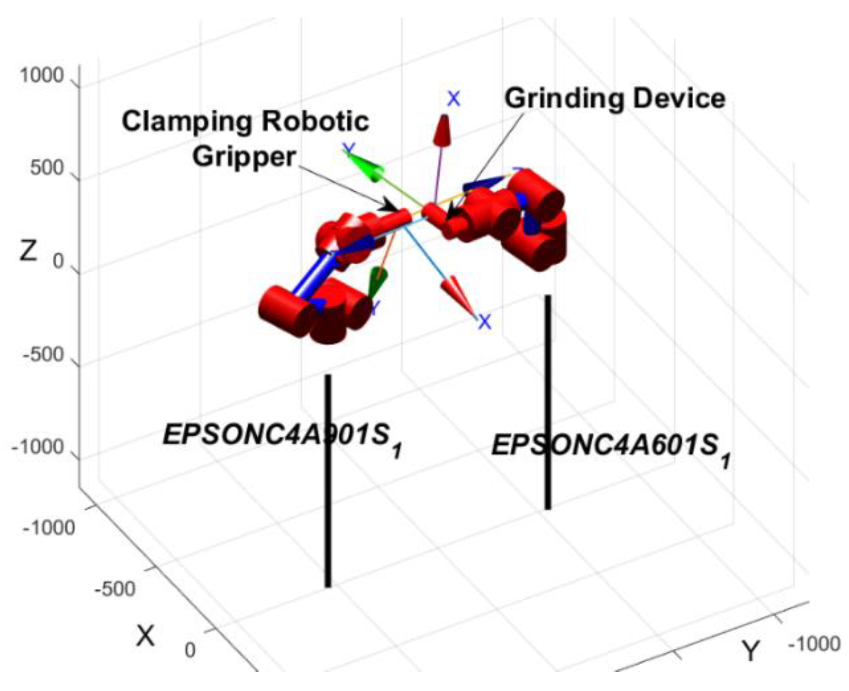
Figure 12.
Workpiece.
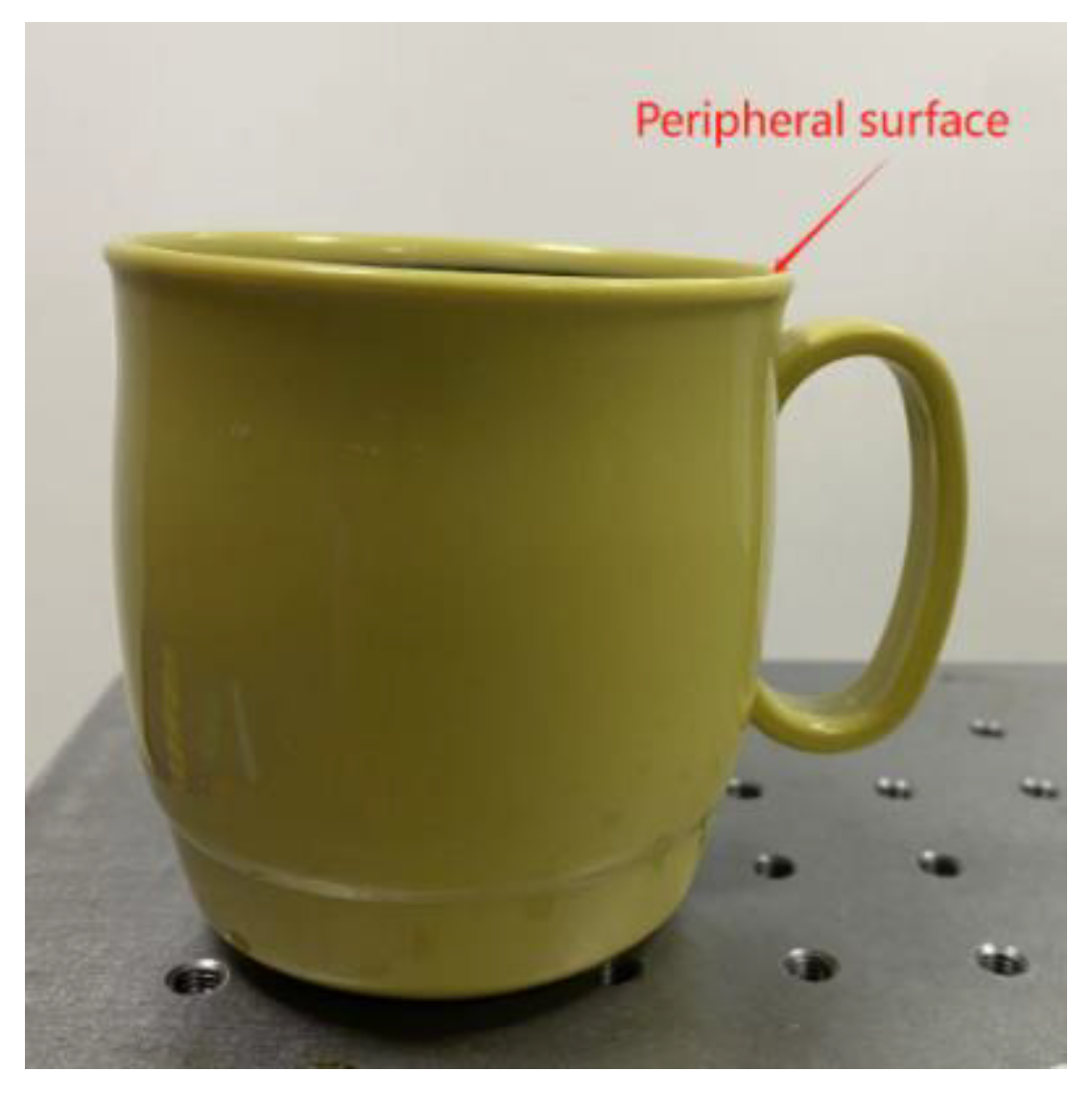
Figure 13.
Joint and Trajectory: a) Joint angle variation diagram of the master robot b) Trajectory profile of the master robot.
Figure 13.
Joint and Trajectory: a) Joint angle variation diagram of the master robot b) Trajectory profile of the master robot.
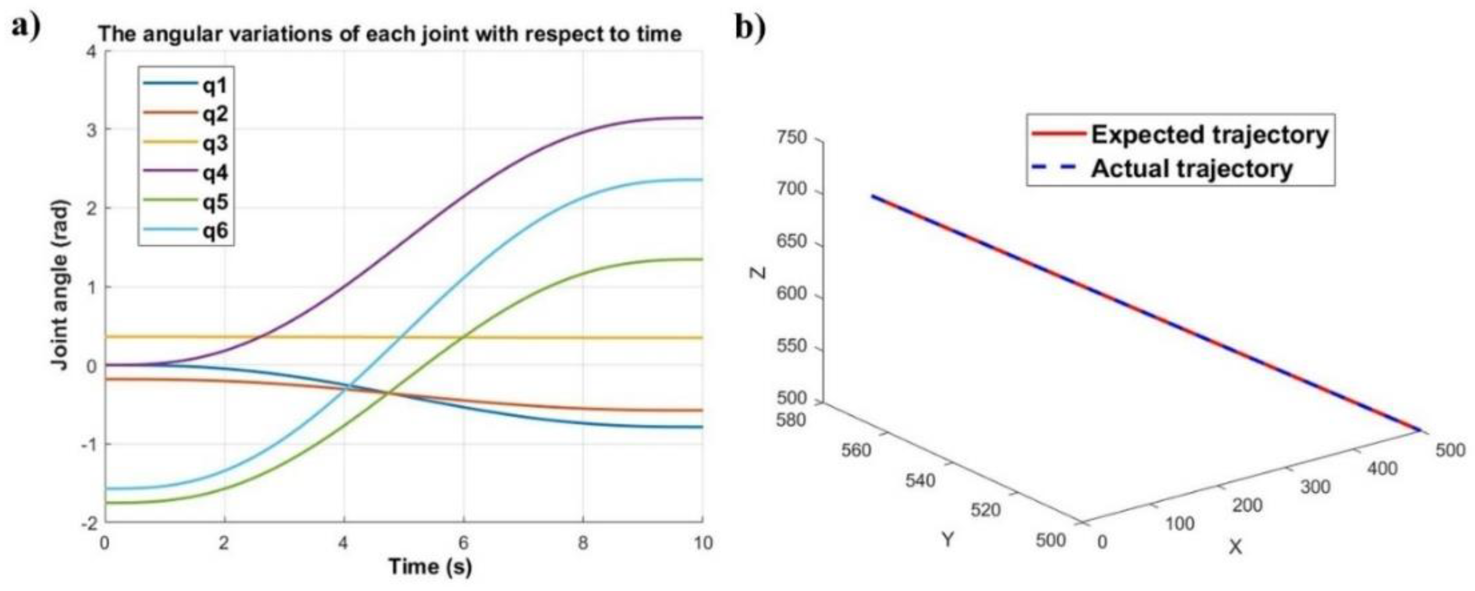
Figure 14.
Joint and Trajectory: Joint transformation diagram of the slave robot b) Trajectory profile of the slave robot.
Figure 14.
Joint and Trajectory: Joint transformation diagram of the slave robot b) Trajectory profile of the slave robot.
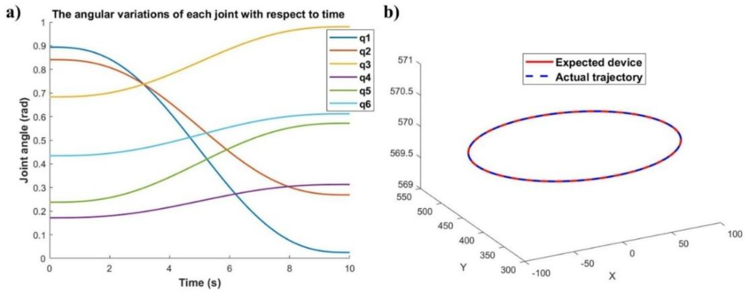
Figure 15.
Dual-Robot Collaborative Motion Experimental Platform.
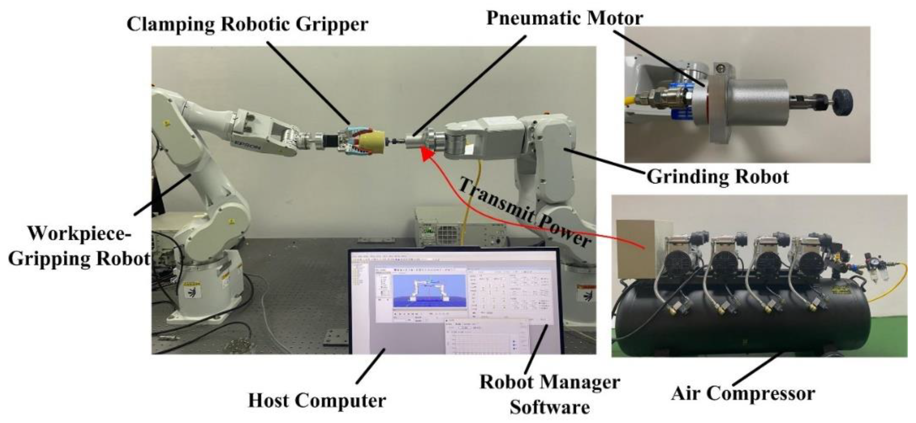
Figure 16.
Key phases in dual-robot collaborative motion: a) Initial pose configuration b) First-quarter trajectory pose c) Mid-trajectory pose d) Third-quarter trajectory pose.
Figure 16.
Key phases in dual-robot collaborative motion: a) Initial pose configuration b) First-quarter trajectory pose c) Mid-trajectory pose d) Third-quarter trajectory pose.
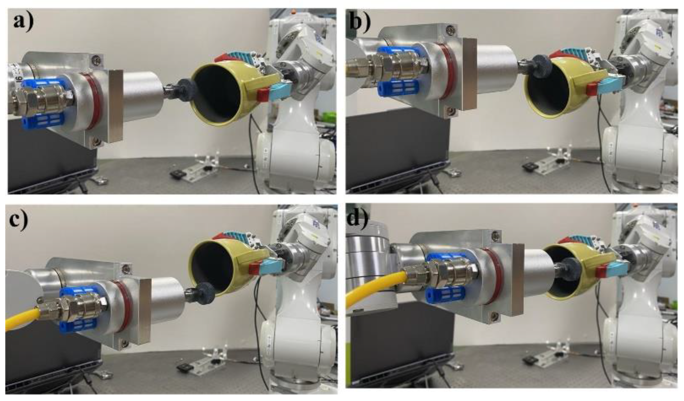
Figure 17.
trajectory and error: a) Slave Robot motion tracking trajectory, b) Slave Robot motion tracking error.
Figure 17.
trajectory and error: a) Slave Robot motion tracking trajectory, b) Slave Robot motion tracking error.
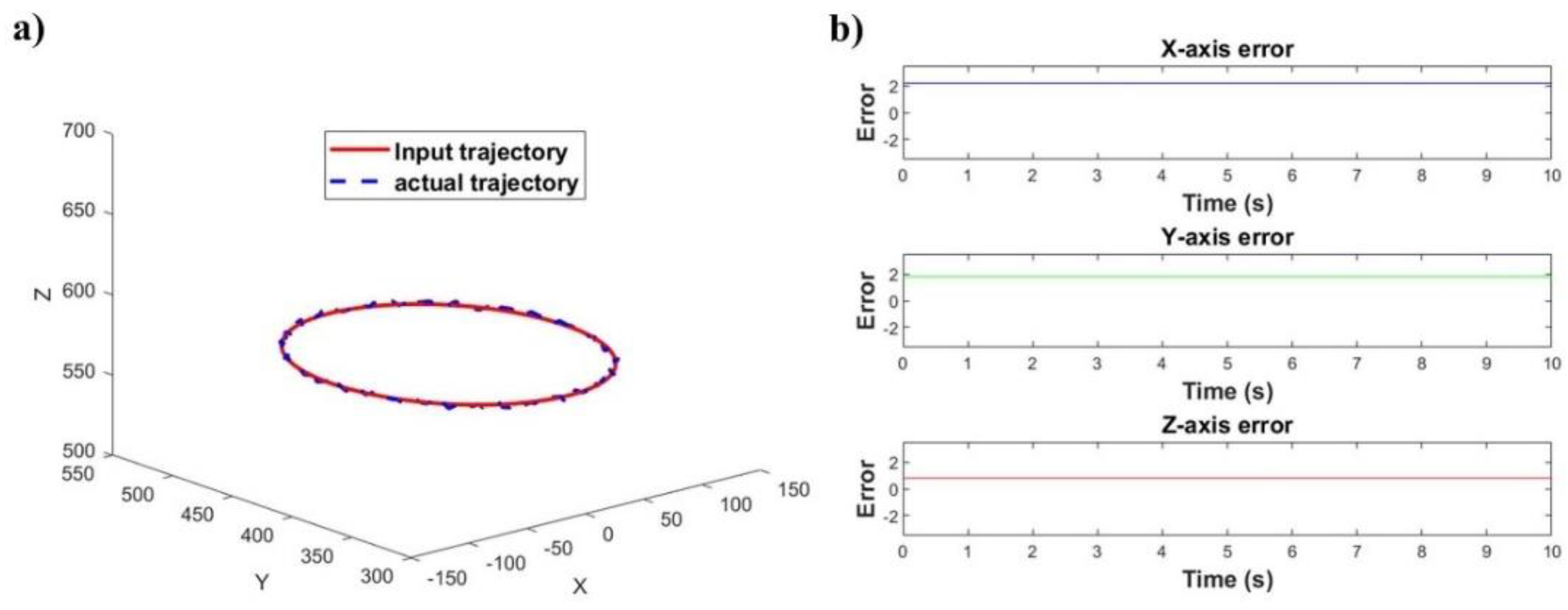

Table 1.
End-effector position of the master robot.
| Serial numbers | x -axis coordinate | y -axis coordinate | z -axis coordinate |
| 1 | -594.215 | 6.354 | 578.290 |
| 2 | -544.215 | 6.154 | 577.740 |
| 3 | -593.715 | 6.354 | 628.590 |
| 4 | -593.915 | -3.646 | 608.590 |
Table 2.
End-effector position of the slave robot.
| Serial numbers | x -axis coordinate | y -axis coordinate | z -axis coordinate |
| 1 | 485.858 | 0 | 572.732 |
| 2 | 535.857 | 0 | 572.732 |
| 3 | 485.858 | 0 | 622.732 |
| 4 | 485.858 | -10 | 602.732 |
Table 3.
Slave Robot end-effector pose (Identical spatial point).
| Serial numbers | 1 | 2 | 3 | 4 |
| X/mm | 148.382 | 155.438 | 123.038 | 110.071 |
| Y/mm | 407.927 | 422.299 | 389.444 | 405.634 |
| Z/mm | 168.750 | 180.865 | 112.602 | 77.893 |
| U/rad | 75.788 | 67.484 | 90.894 | 97.282 |
| V/rad | -31.891 | -30.336 | -40.751 | -31.282 |
| W/rad | 177.146 | -177.802 | 156.621 | 141.267 |
Table 4.
From the end-effector pose of the slave robot (Translation).
| Serial numbers | 5 | 6 | 7 |
| X/mm | 0 | 50 | 0 |
| Y/mm | 415 | 415 | 465 |
| Z/mm | 570 | 570 | 570 |
| U/rad | 0 | 0 | 0 |
| V/rad | -90 | -90 | -90 |
| W/rad | -90 | -90 | -90 |
Table 5.
MDH Parameter Table of EPSONC4-A901S robot.
| Joint i | αi/rad | ai/mm | θi/rad | di/mm | βi/rad |
| 1 | 0 | 0 | pi/2 | 320 | 0 |
| 2 | pi/2 | 100 | pi/2 | 0 | 0 |
| 3 | 0 | 400 | 0 | 0 | 0 |
| 4 | -pi/2 | 0 | 0 | -400 | 0 |
| 5 | pi/2 | 0 | 0 | 0 | 0 |
| 6 | -pi/2 | 0 | 0 | -65 | 0 |
Disclaimer/Publisher’s Note: The statements, opinions and data contained in all publications are solely those of the individual author(s) and contributor(s) and not of MDPI and/or the editor(s). MDPI and/or the editor(s) disclaim responsibility for any injury to people or property resulting from any ideas, methods, instructions or products referred to in the content. |
© 2025 by the authors. Licensee MDPI, Basel, Switzerland. This article is an open access article distributed under the terms and conditions of the Creative Commons Attribution (CC BY) license (http://creativecommons.org/licenses/by/4.0/).
Copyright: This open access article is published under a Creative Commons CC BY 4.0 license, which permit the free download, distribution, and reuse, provided that the author and preprint are cited in any reuse.