
Submitted:
15 May 2025
Posted:
16 May 2025
You are already at the latest version
Abstract
Crash boxes play a crucial role in mitigating forces during vehicle collisions by absorbing impact energy. Additive manufacturing (AM), particularly Fused Deposition Modeling (FDM), has emerged as a promising method for their fabrication due to its design flexibility and continuous advancements in material development. This study investigates the crash performance of tapered crash box configurations, each manufactured using two FDM materials: Carbon Fiber Reinforced Polylactic Acid (PLA-CF) and Polylactic Acid Plus (PLA+). The specimens vary in wall thickness and taper angles to evaluate the influence of geometric and material parameters on crashworthiness. Results demonstrate that both Specific Energy Absorption (SEA) and Crush Force Efficiency (CFE) increase with wall thickness and taper angle, with PLA-CF consistently outperforming PLA+ in both metrics. Regression models were developed based on experimental data to predict SEA and CFE with a maximum absolute percentage error of 4.97%. These models guided the design of new configurations, with the optimal case achieving an SEA of 31.53 kJ/kg and a CFE of 0.81. The findings confirm the effectiveness of the modeling approach and underscore the potential of PLA-CF in enhancing the energy absorption capability of crash boxes, particularly in tapered designs.
Keywords:
additive manufacturing
; 3D printing
; crashworthiness
; energy absorption
; tapered tubes
; crash box
1. Introduction
Crash boxes are critical components designed to absorb impact energy during vehicle collisions, reducing the force transmitted to the main structure and enhancing occupant safety. Positioned between the side rails and the bumper, they are specifically engineered to deform upon impact, effectively dissipating energy. Crashworthiness refers to a crash box's ability to absorb impact energy and protect occupants during a collision [1]. Traditionally, crash boxes have been manufactured using processes such as composite fabrication [2], wire electrical discharge machining [3,4,5], extrusion [6,7,8], welding [9,10], CNC water jet cutting [11], and stamping [12,13], which limit their geometric complexity. Recent advances in additive manufacturing (AM), also known as 3D-printing and originally introduced by Charles Hull in 1984 [14], have expanded design possibilities, enabling the production of intricate geometries previously unattainable with conventional methods. Additionally, AM allows for the use of advanced materials with superior mechanical properties. The combination of geometric flexibility and material innovation significantly enhances the crashworthiness of additively manufactured crash boxes. Among various AM techniques, Fused Deposition Modeling (FDM) has gained widespread adoption due to its accessibility, versatility, and advancements in both technology and material development, making it increasingly efficient, cost-effective, and suitable for crash box production [15].
Several studies have compared different materials used in FDM to assess their impact on the energy-absorbing performance [16,17,18]. For example, Zhang et al. [19] investigated metamaterial lattice structures fabricated with Polylactic Acid (PLA) and Polyethylene Terephthalate Glycol (PETG). Their study examined unit-cell configurations, including hexagonal, hybrid, and re-entrant layouts, with the PETG re-entrant honeycomb demonstrating the highest performance. Similarly, Isaac et al. [20] investigated the performance of five polymer-based honeycomb lattice structures fabricated from four different materials: PLA, PETG, ABS (Acrylonitrile Butadiene Styrene), ASA (Acrylonitrile Styrene Acrylate), and PA-CF (Polyamide-Carbon Fiber), highlighting PETG's superior energy absorption performance. Furthermore, Wang et al. [21] explored the energy absorption properties of thin-walled tubular structures made from PA (Polyamide), PA-CF, and PA-GF (Polyamide-Glass Fiber). They concluded that PA-CF exhibited the highest energy absorption performance.
In addition to material considerations, the geometric configurations enabled by FDM technology have been extensively investigated to enhance energy absorption performance [22,23,24]. Wang et al. [25] examined multi-cell-filled tubes with internal cell geometries, including circular, hexagonal, and triangular shapes, all fabricated from PA-CF. They concluded that circular-filled configurations demonstrated superior energy absorption compared to both hexagonal and triangular designs. Liu et al. [26] explored stepwise graded multi-cell tubes (SGMTs) and continuous graded multi-cell tubes (CGMTs), produced using PA-CF. Their findings showed that CGMTs offered improved energy absorption due to the absence of discontinuous interfaces, which contributed to more uniform deformation. Liu et al. [27] investigated assembled and integrated lattice-filled multi-cell tubes made from PA-CF. Their integrated designs exhibited enhanced performance, benefiting from a synergistic effect between the lattice and tube structures, resulting in greater energy absorption than the sum of their individual components.
The continuous development of FDM materials, such as Carbon Fiber Reinforced Polylactic Acid (PLA-CF), and Polylactic Acid Plus (PLA+), has opened new possibilities for producing crash boxes with enhanced energy absorption capacities. However, a systematic comparison between these two materials has not yet been explored. In this study, the crash performance of nine distinct tapered tube crash box designs was investigated, with each design printed once using PLA+ and once using PLA-CF, resulting in a total of 18 specimens. The specimens featured varying wall thicknesses and tapered angles to comprehensively assess their effects on crash performance. Upon completing the testing of 18 specimens, the best candidates were further investigated by varying the thickness and the taper angle. The additional three experiments concluded the investigation. This study highlights how material and geometric parameters together affect crashworthiness, aiding the design of more effective FDM-manufactured crash boxes. The results of this study can serve as benchmark results for finite element analysis comparison.
2. Experimental Procedure
2.1. Geometrical Design
A tapered tube geometry was adopted in this study to evaluate and compare the crashworthiness performance of different FDM materials, as tapered configurations have demonstrated superior energy absorption characteristics compared to straight tubes [28]. All specimens maintained a consistent height (H) of 60 mm and an outer base diameter (D) of 30 mm. To systematically investigate geometric parameters, three different wall thicknesses of 1 mm, 1.5 mm, and 2 mm were considered. Additionally, three different taper angles of 0°, 2.5°, and 5° were adapted, resulting in nine distinct design configurations. A 50 mm × 50 mm base plate with a thickness of 2 mm was integrated into the bottom of each specimen to ensure stability and prevent slippage during compression testing. The specimen geometry and dimensional specifications are illustrated in Figure 1.
2.2. Materials and Processing Parameters
In this study, all specimens were fabricated using a 1.75 mm filament provided by Shenzhen eSUN Industrial Co., Ltd., with the corresponding mechanical properties summarized in Table 1 based on manufacturer specifications. The geometrical models were created using SOLIDWORKS and exported in STL (Standard Tessellation Language) format. These STL files were processed in PrusaSlicer, developed by Prusa Research, to generate G-code instructions for the Prusa XL FDM 3D printer used in fabrication. To ensure print consistency and mechanical reliability, printing parameters were selected following the recommendations of both the filament and printer manufacturers. The applied printing conditions are detailed in Table 2. Figure 2a displays the final printed specimens, each labeled on its integrated base for identification. These alphanumeric labels denote specific geometrical and material attributes; for instance, “T2A0C” corresponds to a 2 mm wall thickness, 0° taper angle, and PLA-CF material, while “T1A2.5+” represents a 1 mm wall thickness, 2.5° taper angle, and PLA+ material. For each PLA+ and PLA-CF specimen, a separate base (50 mm × 50 mm × 2 mm) was 3D printed, as illustrated in Figure 2b.
2.3. Experimental Method
Quasi-static axial compression tests were conducted at room temperature to assess the crashworthiness of the fabricated specimens. A Tinius Olsen universal testing machine (Model 50ST) equipped with a 50 kN load cell, as shown in Figure 3, was used for testing. Prior to testing, the specimen's total mass, including the base, was measured, and the mass of the base was subtracted to determine the mass of the specimen alone. The specimens were placed between the two flat plates of the testing machine. The lower plate incorporated a 3D-printed frame with a groove (50 mm × 50 mm × 2 mm) that securely held the specimen base in position, ensuring proper alignment and preventing slippage during compression, as shown in Figure 3. The upper plate moved downward at a speed of 5 mm/min [29,30], applying a compressive force on the specimens, with the crushing displacement set to 2/3 of the specimen's original height [25,31]. Force-displacement data were continuously recorded during the compression tests.
2.4. Definition of Crashworthiness Indicators
Crash box performance is typically evaluated through key metrics that indicate its ability to absorb impact forces. These metrics are derived from the force–displacement curve. The primary parameters used for this evaluation are summarized below [32]:
2.4.1. Total Energy Absorption,
The total energy absorption of a crash box can be determined by calculating the work done by the crushing force. It is represented by the area under the axial force versus the axial displacement curve. is expressed as:
where, is the crushing force, is the displacement, and is the total crush displacement.
2.4.2. Peak Crush Force,
The peak crush force is the maximum force observed in the axial direction during the crushing process.
2.4.3. Mean Crush Force,
The mean crush force is defined as the total energy absorbed per unit of total crush displacement. It is expressed as:
2.4.4. Specific Energy Absorption,
Specific energy absorption is defined as the total energy absorbed per unit mass of the crash box. It is expressed as:
where, is the mass of the crash box. A higher indicates greater energy absorption per unit mass, which helps reduce the kinetic energy transmitted to occupants and thereby enhances safety [33].
2.4.5. Crush Force Efficiency,
Crush force efficiency is defined as the ratio of the to the . It is expressed as:
A higher reflects a lower , resulting in less force being transferred to the passenger [33].
3. Results and Discussion
3.1. Post-Compression Behavior of Tested Specimens
The post-compression condition of the tested specimens is presented in Figure 4. Most configurations demonstrated a favorable progressive folding pattern, characterized by the sequential and uniform formation of folds, indicating stable deformation and efficient energy absorption. PLA-CF specimens generally exhibited more localized fractures compared to PLA+ specimens, suggesting that the inclusion of carbon fibers in PLA-CF may contribute to a more brittle failure response under compressive loading. Specimen T1A0C, however, deviated from this behavior, experiencing brittle fracture instead of folding, which significantly reduced the energy absorption. This failure is attributed to its basic cylindrical geometry with a 0° taper angle, a reduced wall thickness of 1 mm, and the inherently brittle nature of PLA-CF. These results indicate that increasing the wall thickness and taper angle may help reduce the occurrence of brittle fracture.
3.2. Force-Displacement Curves
The force-displacement curves for the different design configurations are presented in Figure 5. The curves reveal varied behaviors under axial compression, with the majority of configurations showing consistent and uniform plastic deformation, except for T1A0C, which displayed brittle fracture. The was observed within the displacement range of 1-5 mm for all configurations. The highest , recorded for T2A0+ and T2A0C at 11.963 kN and 12.155 kN, respectively. In contrast, the lowest values were observed in T1A5+ and T1A5C, with forces of 3.934 kN and 4.084 kN. After reaching the peak, all specimens transitioned into a more stable force region, where the load fluctuated around a mean crush force, indicating continuous energy absorption.
3.3. Crashworthiness Indicators
The crashworthiness indicators , , , , and for various design configurations fabricated from PLA-CF and PLA+ are presented in Table 3, including the mass of each specimen. Column charts are utilized to visually present the crashworthiness indicators, as illustrated in Figure 6. The mass of the specimens clearly depends on both geometric configuration and material type. Specifically, mass increases with wall thickness and decreases with larger taper angles. PLA-CF consistently displays values comparable to or slightly lower than PLA+, which is attributable to its slightly lower density (1.21 g/cm³) relative to that of PLA+ (1.23 g/cm³). The highest mass, recorded in T2A0C and T2A0+, is 12.2 g, while the lowest, observed in T1A5C, is 5.1 g.
For , values rise with increased wall thickness and show minimal sensitivity to taper angle variations. PLA-CF generally outperforms PLA+ in , except in configuration T1A0C, where brittle fracture limited the value to 0.01 kJ. The maximum is achieved in T2A2.5C at 0.243 kJ.
is influenced by both geometric parameters, increasing with thickness and decreasing with greater taper angle, a well-established behavior in tapered structures. PLA-CF generally yields slightly higher than PLA+. The highest value is observed in T2A0C at 12.155 kN, and the lowest in T1A5+ at 3.934 kN.
follows a trend comparable to , with values rising as thickness increases and showing limited dependence on the taper angle. PLA-CF typically produces higher than PLA+, aside from T1A0C, which experienced a brittle failure, reducing to 0.172 kN. The peak value, 6.073 kN, is attained at T2A2.5C.
is responsive to both geometric parameters, increasing with thickness and taper angle. Although remains largely unchanged with taper angle, the concurrent reduction in results elevated , as it is dependent on both. Higher indicates enhanced energy absorption per unit mass, contributing to reduced kinetic energy transfer to occupants. PLA-CF generally exhibits superior performance compared to PLA+. T2A5C achieves the highest at 23.5 kJ/kg, whereas T1A0C, due to brittle failure, shows the lowest value of 1.112 kJ/kg.
similarly increases with both thickness and taper angle. While remains relatively stable with changing taper angle, the associated decline in improves , as it is defined by the -to- ratio. Higher reflects better load stability during deformation, minimizing forces transferred to occupants. PLA-CF configurations consistently yield higher values than PLA+, with the most favorable outcome observed in T2A5C at 0.704. Conversely, the lowest value of 0.028 occurs in T1A0C due to brittle failure.
4. Regression analysis
The experiment involved varying three parameters: thickness, taper angle, and filament material. These parameters were used to develop regression models for predicting output responses, specifically for and . To model these responses, a second-order polynomial response surface (PRS) approach was used. The general form of the second-order polynomial model is expressed as [34]:
where, represents an approximation of the actual response function ( or ), consists of variables (thickness and taper angle ), and the coefficients , , , and are the regression coefficients determined using the least-squares technique. For each filament material, two separate regression models were developed: one for and one for . MATLAB functions polyfitn and polyvaln were utilized for polynomial fitting and evaluation of the model predictions, respectively. The case T1A0C was excluded from the training points due to early specimen failure, potentially leading to incorrect model predictions. The regression models for PLA-CF and PLA+ are presented below:
To evaluate the accuracy of the generated models, two numerical estimators, namely R-squared and Maximum Absolute Percentage Error , are employed to validate the models, as outlined in Eqs. (10) and (11) [35]. The resulting values are provided in Table 4.
where, is the total number of data points, is the actual value, is the predicted value, is the mean of the actual values.
The 3D contour plots of the and models for both PLA-CF and PLA+ are illustrated in Figure 7, providing a detailed visualization of their predictive performance. In all plots, the regression models accurately interpolate the training data. It is observed that both and increase with greater thickness and taper angle, with PLA-CF consistently outperforming PLA+. Higher and values indicate enhanced crashworthiness by improving energy absorption and reducing the force transmitted to occupants. These trends suggest that increasing both thickness and taper angle can lead to improved crash performance. Based on this observation, three additional design cases are proposed, as shown in Figure 8a: T2A7.5C, T2.5A7.5C, and T3A7.5C.
The condition of the T2A7.5C, T2.5A7.5C, and T3A7.5C specimens after the compression test is shown in Figure 8b, and the corresponding crashworthiness indicators, including the mass of each specimen, are summarized in Table 5. Among these configurations, T3A7.5C demonstrated the highest performance, achieving a of 31.53 kJ/kg and a of 0.81. These outcomes underscore the superior crashworthiness of the T3A7.5C design and validate the positive influence of increased thickness on both and , supporting the effectiveness of the regression model-guided design strategy.
A comparative evaluation is conducted between the optimal crash box developed in the present study and the leading design configurations reported in recent literature concerning FDM-fabricated tubular crash boxes, as depicted in Figure 9. The figure illustrates the correlation between and for structures manufactured using various materials, including PLA, PLA+, PLA-LW, PA-CF, and TPU. Among the compared designs, the T3A7.5C specimen exhibits the highest while maintaining a substantial relative to the crash boxes reported in previous studies. These findings highlight the strong potential of PLA-CF, particularly in tapered geometries, for high-performance crash box applications.
5. Conclusions
In this study, the crashworthiness performance of 3D-printed tapered tube crash boxes were investigated. The specimens were fabricated using Fused Deposition Modeling (FDM) with two advanced filament materials: PLA-CF and PLA+. A series of nine geometric configurations were designed by varying wall thicknesses and taper angles, and each configuration was printed using both materials to comprehensively evaluate their structural response under quasi-static axial compression. The results demonstrate that greater wall thickness and larger taper angles significantly improve energy absorption characteristics. Across all configurations, PLA-CF consistently outperformed PLA+ in both and , indicating its suitability for energy-dissipating applications. Based on the experimental dataset, second-order polynomial regression models were developed to predict and , yielding a maximum absolute percentage error of 4.97%. These models were further utilized to guide the design of new configurations. The optimal design, defined by a thickness of 3 mm and a taper angle of 7.5 degrees using PLA-CF, achieved an of 31.53 kJ/kg and a of 0.81. The findings highlight the effectiveness of tapered tube designs and the use of PLA-CF material in improving crashworthiness performance.
Author Contributions
Conceptualization, A.S. and M.A.G.; methodology, A.S. and M.A.G.; formal analysis, O.S.E, A.S. and M.A.G.; investigation, O.S.E, A.S. and M.A.G.; resources, A.S. and M.A.G.; data curation, H.A., A.S. and M.A.G.; writing—original draft preparation, O.S.E, H.A., A.A. and Y.A.; writing—review and editing, A.S. and M.A.G.; visualization, A.S. and M.A.G.; supervision, A.S. and M.A.G.; project administration, M.A.G.. All authors have read and agreed to the published version of the manuscript.
Funding
This research received no external funding.
Data Availability Statement
The data presented in this study is available on request from the corresponding author.
Conflicts of Interest
The authors declare no conflicts of interest.
References
- Omar, M.A. The Automotive Body Manufacturing Systems and Processes; John Wiley and Sons, 2011; ISBN 9780470976333. [CrossRef]
- Kathiresan, M.; Manisekar, K.; Rajamohan, V.; Güler, M.A. Investigations on Crush Behavior and Energy Absorption Characteristics of GFRP Composite Conical Frusta with a Cutout under Axial Compression Loading. Mech. Adv. Mater. Struct. 2022, 29, 5360–5377. [Google Scholar] [CrossRef]
- Mert, S.K.; Demiral, M.; Altin, M.; Acar, E.; Güler, M.A. Experimental and Numerical Investigation on the Crashworthiness Optimization of Thin-Walled Aluminum Tubes Considering Damage Criteria. J. Brazilian Soc. Mech. Sci. Eng. 2021, 43, 1–22. [Google Scholar] [CrossRef]
- Güler, M.A.; Mert, S.K.; Altin, M.; Acar, E. An Investigation on the Energy Absorption Capability of Aluminum Foam-Filled Multi-Cell Tubes. J. Brazilian Soc. Mech. Sci. Eng. 2023, 45, 1–27. [Google Scholar] [CrossRef]
- Chen, J.; Li, E.; Liu, W.; Mao, Y.; Hou, S. Crashworthiness Analysis of Novel Cactus-Inspired Multi-Cell Structures under Axial Crushing. Int. J. Mech. Sci. 2024, 268, 109053. [Google Scholar] [CrossRef]
- Hanssen, A.G.; Langseth, M.; Hopperstad, O.S. Static and Dynamic Crushing of Circular Aluminum Extrusions with Aluminum Foam Filler. Int. J. Impact Eng. 2000, 24, 475–507. [Google Scholar] [CrossRef]
- Hanssen, A.G.; Langseth, M.; Hopperstad, O.S. Static and Dynamic Crushing of Square Aluminum Extrusions with Aluminum Foam Filler. Int. J. Impact Eng. 2000, 24, 347–383. [Google Scholar] [CrossRef]
- Acar, E.; Altin, M.; Güler, M.A. Evaluation of Various Multi-Cell Design Concepts for Crashworthiness Design of Thin-Walled Aluminum Tubes. Thin-Walled Struct. 2019, 142, 227–235. [Google Scholar] [CrossRef]
- Wesselmecking, S.; Kreins, M.; Dahmen, M.; Bleck, W. Material Oriented Crash-Box Design – Combining Structural and Material Design to Improve Specific Energy Absorption. Mater. Des. 2022, 213, 110357. [Google Scholar] [CrossRef]
- Kaczyński, P.; Makuła, P. Constitutive Strength Model for Spot Joints of Thin-Walled Energy-Absorbing Elements. Eng. Struct. 2023, 292, 116592. [Google Scholar] [CrossRef]
- Aktaş, C.; Acar, E.; Güler, M.A.; Altın, M. An Investigation of the Crashworthiness Performance and Optimization of Tetra-Chiral and Reentrant Crash Boxes. Mech. Based Des. Struct. Mach. 2023, 51, 6881–6904. [Google Scholar] [CrossRef]
- Ma, J.; Dai, H.; Shi, M.; Yuan, L.; Chen, Y.; You, Z. Quasi-Static Axial Crushing of Hexagonal Origami Crash Boxes as Energy Absorption Devices. Mech. Sci. 2019, 10, 133–143. [Google Scholar] [CrossRef]
- Yuan, L.; Shi, H.; Ma, J.; You, Z. Quasi-Static Impact of Origami Crash Boxes with Various Profiles. Thin-Walled Struct. 2019, 141, 435–446. [Google Scholar] [CrossRef]
- Charles W. Hull, Arcadia, C. Apparatus for Production of Three Dimensional Objects by Stereolithography 1986.
- Capasso, I.; Andreacola, F.R.; Brando, G. Additive Manufacturing of Metal Materials for Construction Engineering: An Overview on Technologies and Applications. Metals (Basel). 2024, 14, 1033. [Google Scholar] [CrossRef]
- Zhou, J.; Liu, H.; Dear, J.P.; Falzon, B.G.; Kazancı, Z. Comparison of Different Quasi-Static Loading Conditions of Additively Manufactured Composite Hexagonal and Auxetic Cellular Structures. Int. J. Mech. Sci. 2023, 244, 108054. [Google Scholar] [CrossRef]
- Tunay, M.; Bardakci, A. A Study of Crashworthiness Performance in Thin-Walled Multi-Cell Tubes 3D-Printed from Different Polymers. J. Appl. Polym. Sci. 2024. [Google Scholar] [CrossRef]
- Hidayat, D.; Istiyanto, J.; Sumarsono, D.A.; Kurniawan, F.; Ardiansyah, R.; Wandono, F.A.; Nugroho, A. Investigation on the Crashworthiness Performance of Thin-Walled Multi-Cell PLA 3D-Printed Tubes: A Multi-Parameter Analysis. Designs 2023, 7, 108. [Google Scholar] [CrossRef]
- Zhang, D.; Li, M.; Qiu, N.; Yang, J.; Wu, C.; Steven, G.; Li, Q.; Fang, J. 4D-Printed Reusable Metamaterial via Shape Memory Effect for Energy Dissipation. Int. J. Mech. Sci. 2024, 275, 109309. [Google Scholar] [CrossRef]
- Isaac, C.W.; Sokołowski, A.; Duddeck, F.; Adamiak, M.; Pakieła, W.; Aremu, A. Mechanical Characterisation and Crashworthiness Performance of Additively Manufactured Polymer-Based Honeycomb Structures under in-Plane Quasi-Static Loading. Virtual Phys. Prototyp. 2023, 18. [Google Scholar] [CrossRef]
- Wang, J.; Liu, Y.; Wang, K.; Yao, S.; Peng, Y.; Rao, Y.; Ahzi, S. Progressive Collapse Behaviors and Mechanisms of 3D Printed Thin-Walled Composite Structures under Multi-Conditional Loading. Thin-Walled Struct. 2022, 171, 108810. [Google Scholar] [CrossRef]
- Sun, G.; Wang, J.; Wang, K.; Baghani, M.; Peng, Y.; Rao, Y. Repeatable Compressive Functionality of 3D Printed Shape-Memory Thin-Walled Corrugated Structures. Int. J. Mech. Sci. 2023, 257, 108552. [Google Scholar] [CrossRef]
- Cetin, E. Energy Absorption of Thin-Walled Multi-Cell Tubes with DNA-Inspired Helical Ribs under Quasi-Static Axial Loading. J. Brazilian Soc. Mech. Sci. Eng. 2024, 46, 607. [Google Scholar] [CrossRef]
- Ha, N.S.; Pham, T.M.; Tran, T.T.; Hao, H.; Lu, G. Mechanical Properties and Energy Absorption of Bio-Inspired Hierarchical Circular Honeycomb. Compos. Part B Eng. 2022, 236, 109818. [Google Scholar] [CrossRef]
- Wang, K.; Liu, Y.; Wang, J.; Xiang, J.; Yao, S.; Peng, Y. On Crashworthiness Behaviors of 3D Printed Multi-Cell Filled Thin-Walled Structures. Eng. Struct. 2022, 254, 113907. [Google Scholar] [CrossRef]
- Liu, Y.; Wang, J.; Tan, Q.; Gao, H.; Wang, K.; Yao, S.; Peng, Y. On Multi-Stage Deformation and Gradual Energy Absorption of 3D Printed Multi-Cell Tubes with Varying Cross-Section. Eng. Struct. 2024, 319, 118839. [Google Scholar] [CrossRef]
- Liu, Y.; Tan, Q.; Lin, H.; Wang, J.; Wang, K.; Peng, Y.; Yao, S. Integrated Design and Additive Manufacturing of Lattice-Filled Multi-Cell Tubes. Compos. Sci. Technol. 2023, 243, 110252. [Google Scholar] [CrossRef]
- Acar, E.; Guler, M.A.; Gereker, B.; Cerit, M.E.; Bayram, B. Multi-Objective Crashworthiness Optimization of Tapered Thin-Walled Tubes with Axisymmetric Indentations. Thin-Walled Struct. 2011, 49, 94–105. [Google Scholar] [CrossRef]
- Li, J.; Qu, M.; Jiang, Z. Multi-Objective Optimization for 3D Printed Origami Crash Box Cell Based on Artificial Neural Networks and NSGA-II. J. Mater. Process. Des. 2023, 7, 1–13. [Google Scholar] [CrossRef]
- Hidayat, D.; Istiyanto, J.; Sumarsono, D.A.; Kurniawan, F.; Abdurohman, K. Crashworthiness Characteristics of Thin-Walled Multi-Cell Structures via the Application of Annealing Process: An Experimental Investigation. Vol. 11, Issue 3, Pages 1892 - 1900. 2024, 11, 1892–1900. [Google Scholar] [CrossRef]
- Wang, K.; Sun, G.; Wang, J.; Yao, S.; Baghani, M.; Peng, Y. Reversible Energy Absorbing Behaviors of Shape-Memory Thin-Walled Structures. Eng. Struct. 2023, 279, 115626. [Google Scholar] [CrossRef]
- Saber, A.; Güler, M.A.; Altin, M.; Acar, E. Bio-Inspired Thin-Walled Energy Absorber Adapted from the Xylem Structure for Enhanced Vehicle Safety. J. Brazilian Soc. Mech. Sci. Eng. 2024, 46, 613. [Google Scholar] [CrossRef]
- Altin, M.; Acar, E.; Güler, M.A. Foam Filling Options for Crashworthiness Optimization of Thin-Walled Multi-Tubular Circular Columns. Thin-Walled Struct. 2018, 131, 309–323. [Google Scholar] [CrossRef]
- Acar, E.; Rais-Rohani, M. Ensemble of Metamodels with Optimized Weight Factors. Struct. Multidiscip. Optim. 2009, 37, 279–294. [Google Scholar] [CrossRef]
- Song, X.; Sun, G.; Li, G.; Gao, W.; Li, Q. Crashworthiness Optimization of Foam-Filled Tapered Thin-Walled Structure Using Multiple Surrogate Models. Struct. Multidiscip. Optim. 2013, 47, 221–231. [Google Scholar] [CrossRef]
- Wirawan, W.A.; Junipitoyo, B.; Putro, S.H.S.; Sabitah, A.; Suudy, A.H.; Ridwan, R.; Choiron, M.A. Collapse Behavior and Energy Absorption Characteristics of Design Multi-Cell Thin Wall Structure 3D-Printed Under Quasi Statistic Loads. Automot. Exp. 2024, 7, 149–160. [Google Scholar] [CrossRef]
- Wang, K.; Tan, Q.; Wang, J.; Liu, Y.; Zhai, Z.; Yao, S.; Peng, Y. A Low-Cost Granular-Medium Hot Quasi-Isostatic Pressing Method for Enhancing Compressive Properties of 3D Printed Structures. J. Manuf. Process. 2024, 115, 441–451. [Google Scholar] [CrossRef]
- M. Awd Allah, M.; Abdel-Aziem, W.; A. Abd El-baky, M. Collapse Behavior and Energy Absorbing Characteristics of 3D-Printed Tubes with Different Infill Pattern Structures: An Experimental Study. Fibers Polym. 2023, 24, 2609–2622. [CrossRef]
Figure 1.
Geometry and dimensional specifications of the specimens.
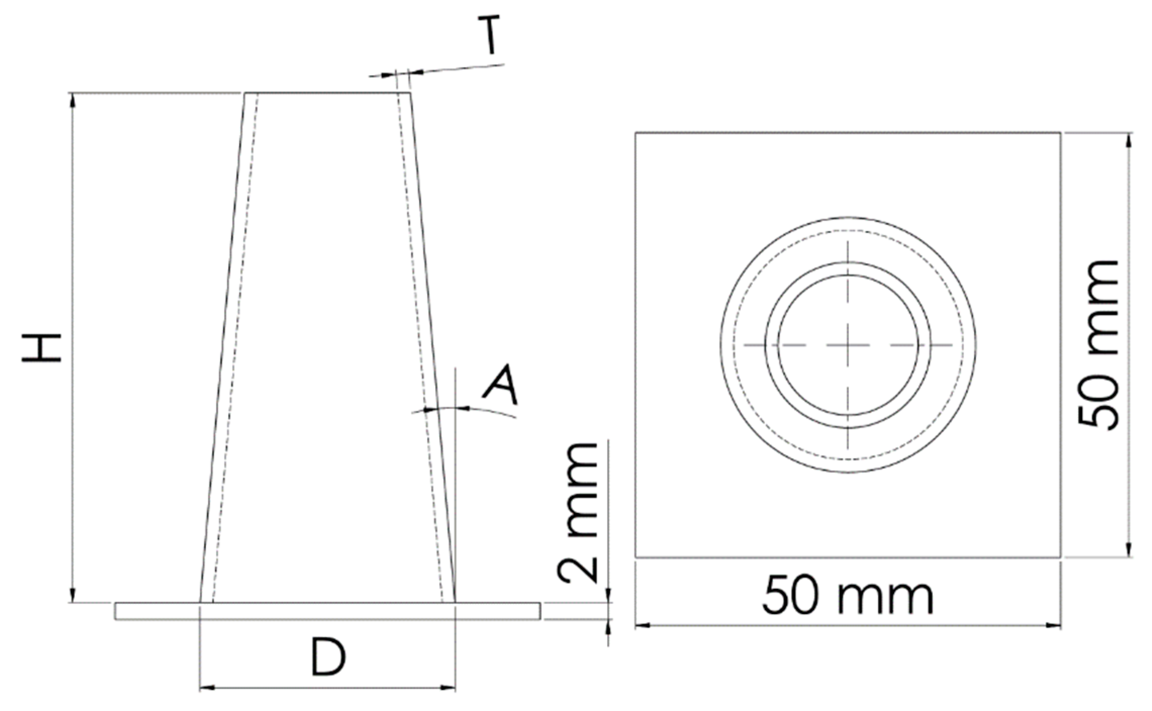
Figure 2.
3D printed (a) PLA+ and PLA-CF specimens; (b) PLA+ and PLA-CF bases.
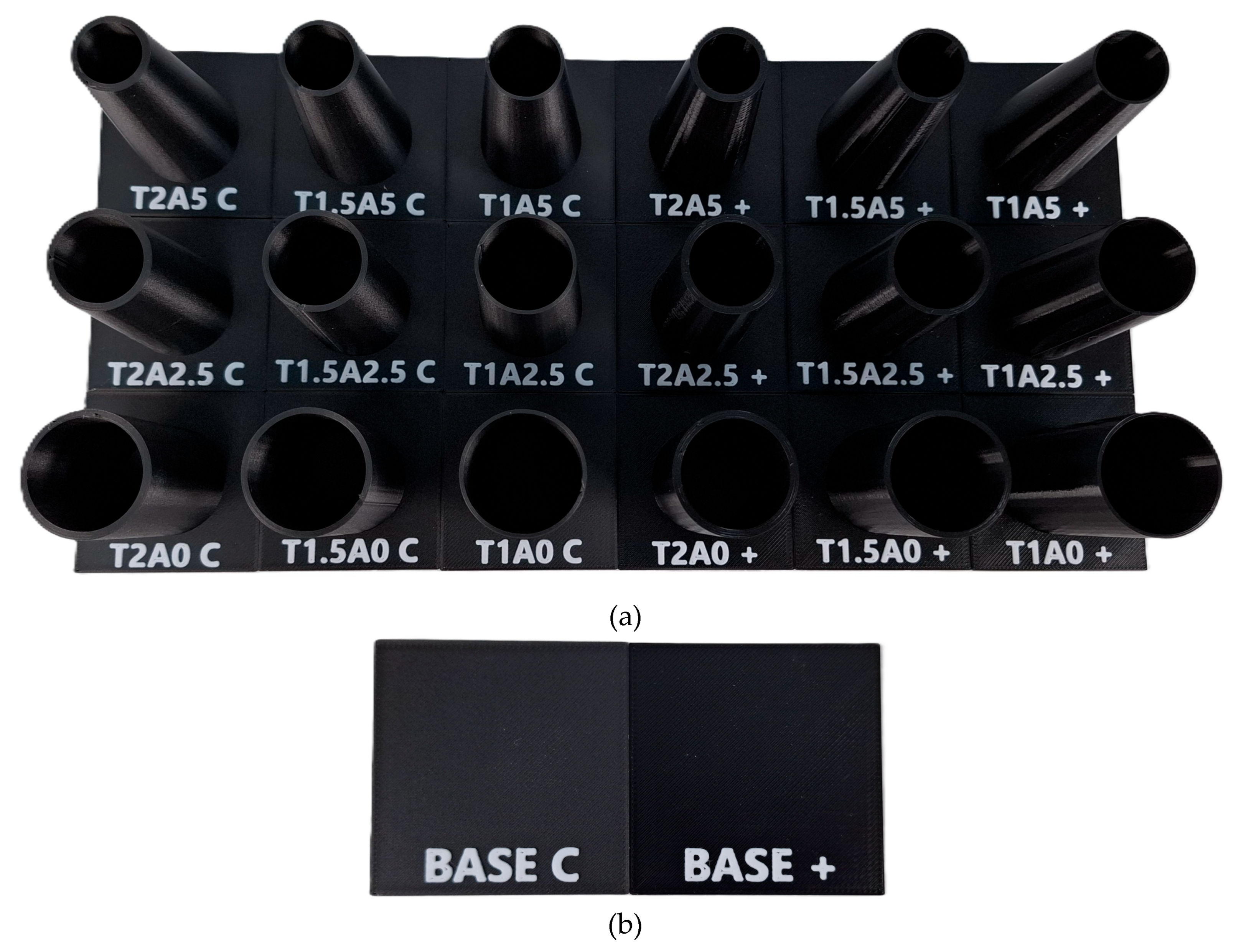
Figure 3.
Tinius Olsen universal testing machine used in the testing of specimens.
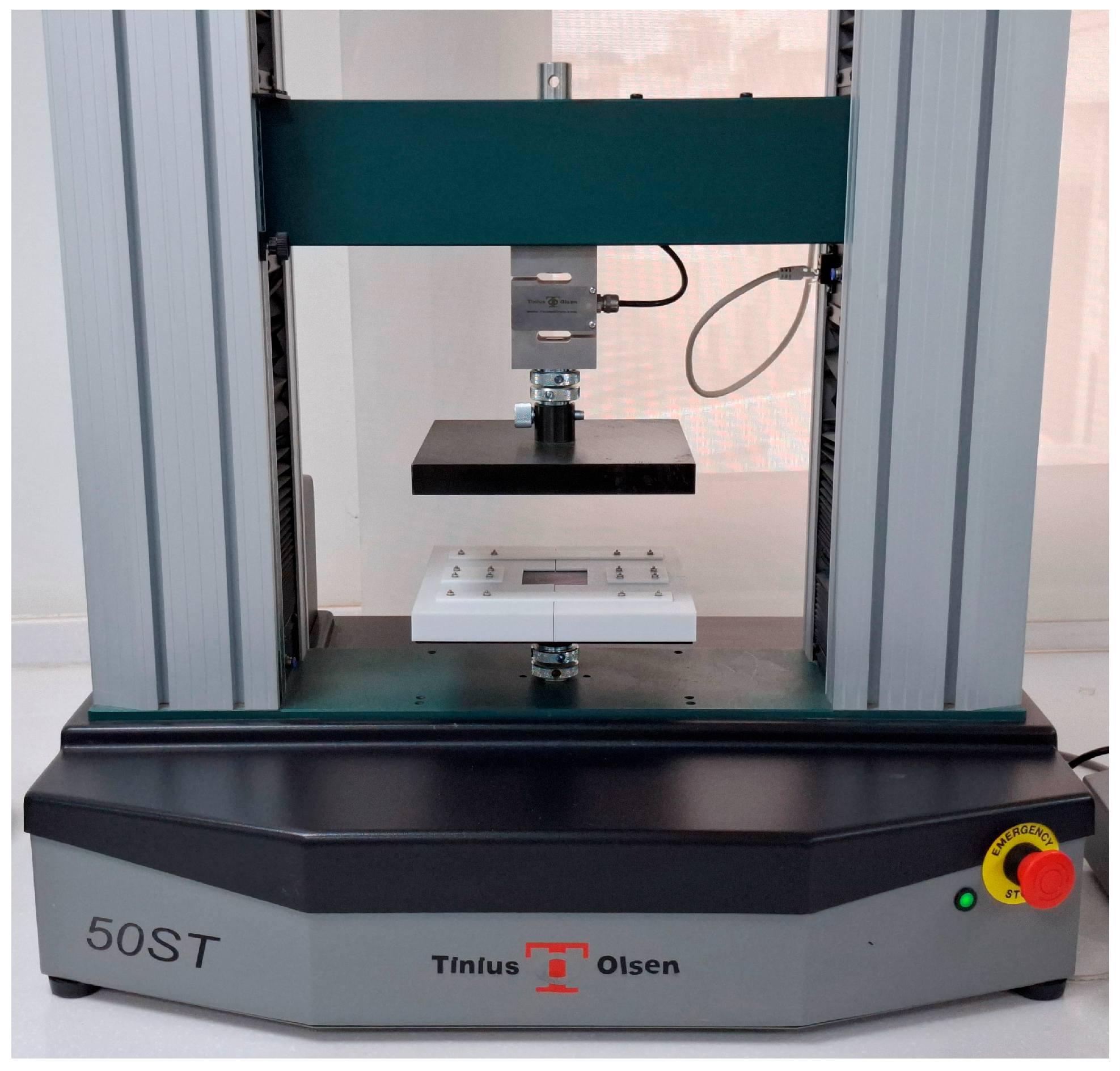
Figure 4.
Condition of specimens after compression testing.
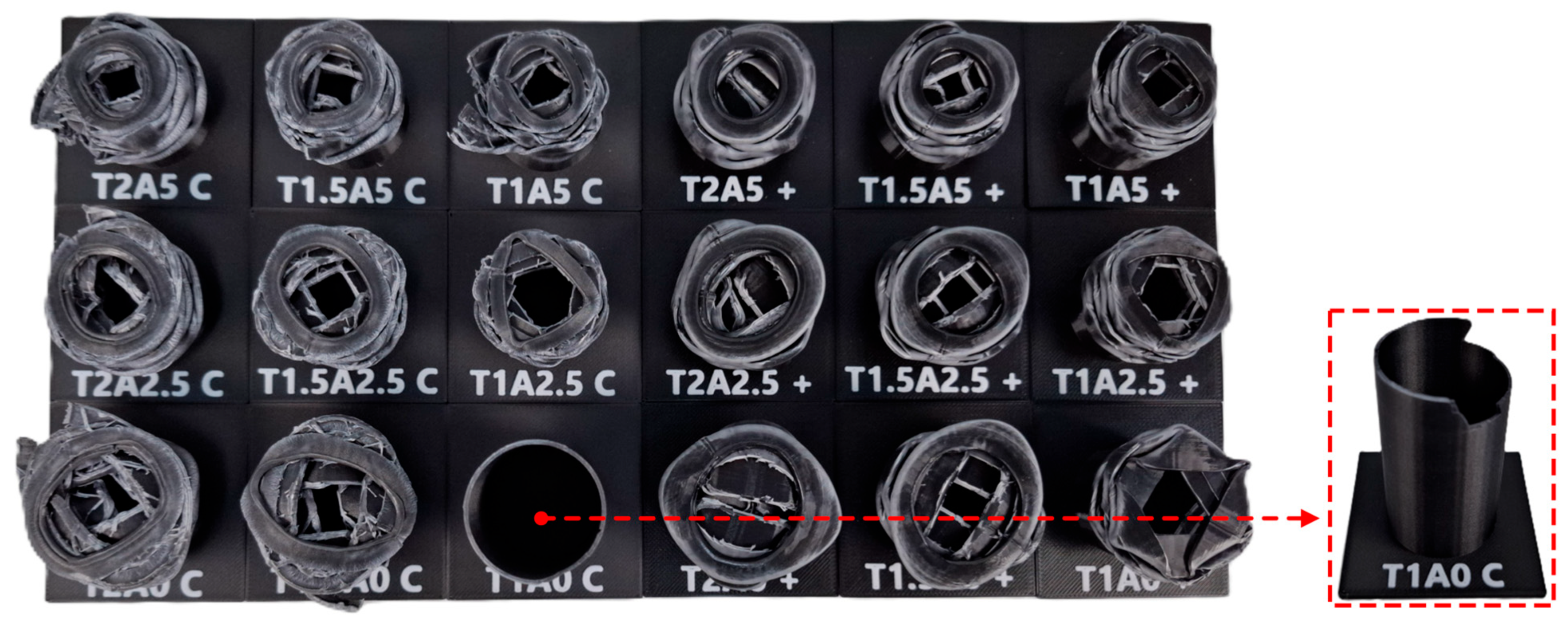
Figure 5.
Force-displacement curves of different design configurations: (a) PLA-CF; (b) PLA+.
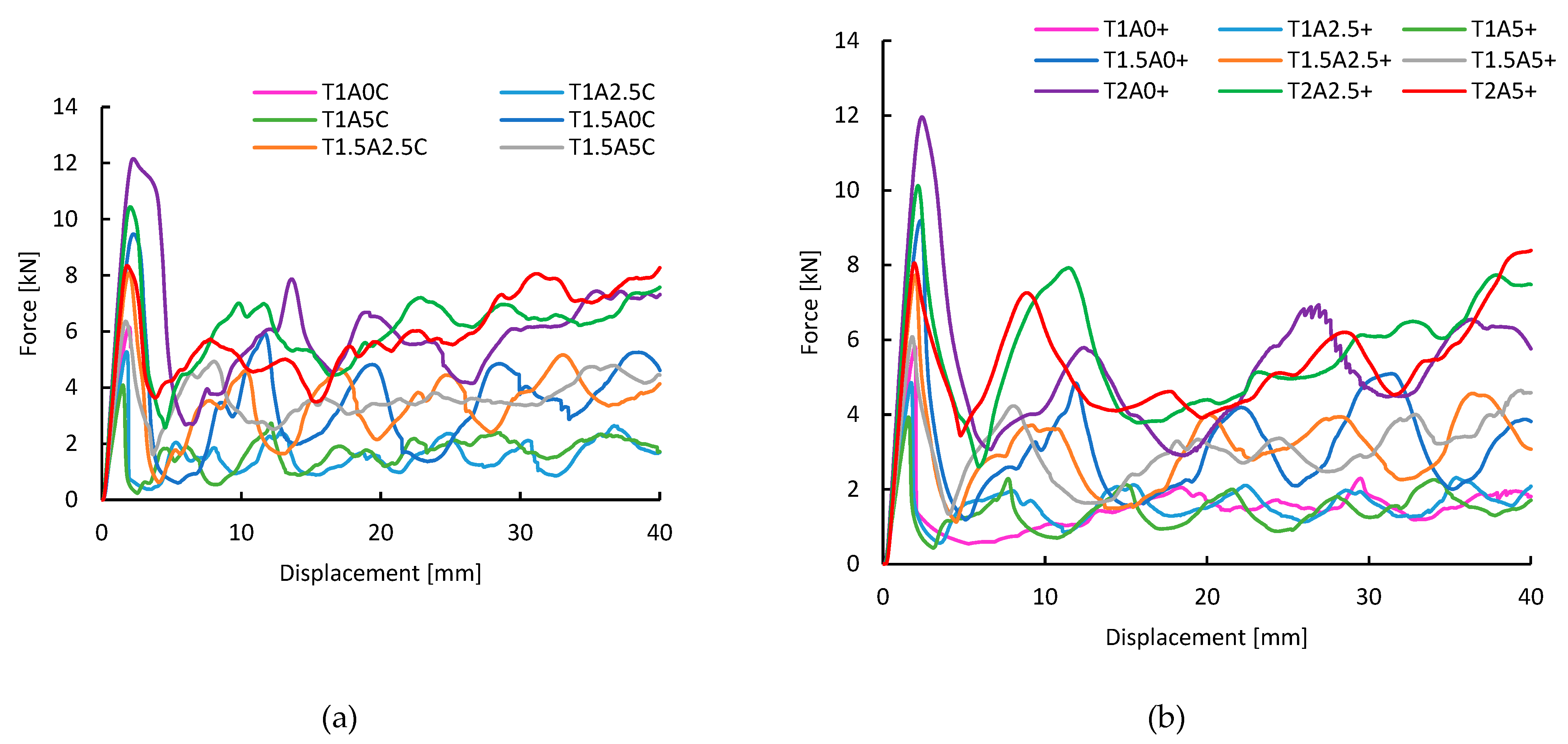
Figure 6.
The mass of each specimen (a) and the crashworthiness indicators: (b) ; (c) ; (d) ; (e) ; (f) .
Figure 6.
The mass of each specimen (a) and the crashworthiness indicators: (b) ; (c) ; (d) ; (e) ; (f) .
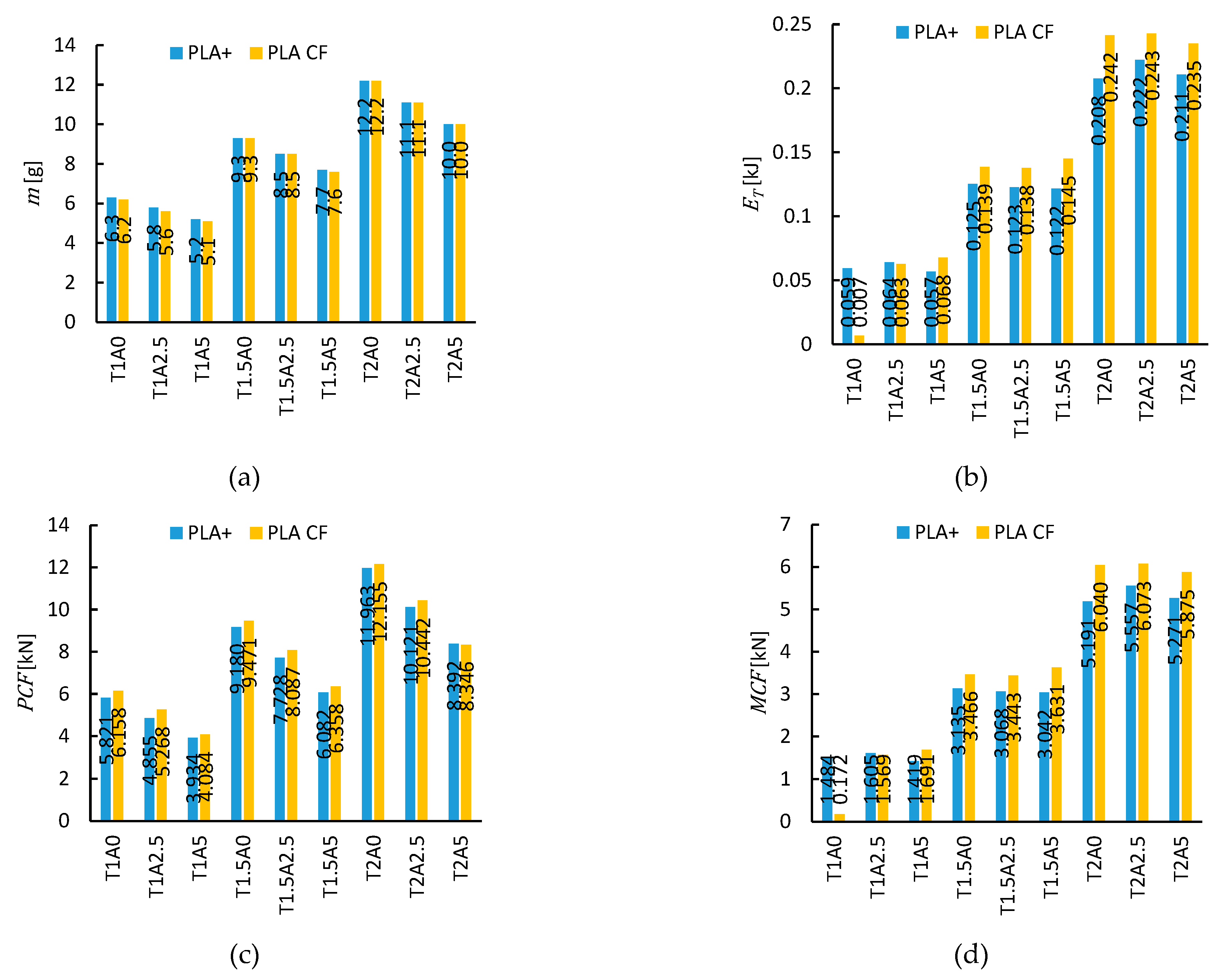
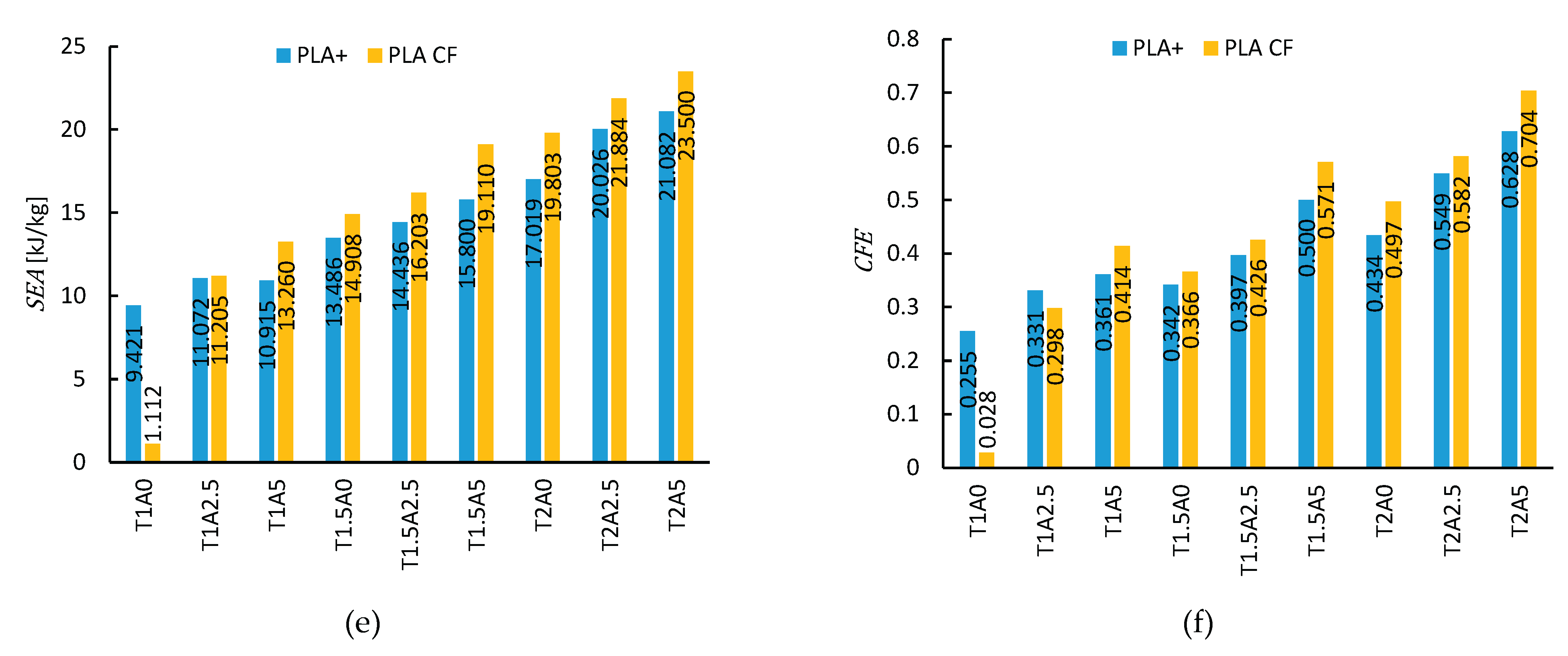
Figure 7.
Regression-based response surfaces with training points indicated by red dots: (a) PLA-CF; (b) PLA+; (c) PLA-CF; (d) PLA+.
Figure 7.
Regression-based response surfaces with training points indicated by red dots: (a) PLA-CF; (b) PLA+; (c) PLA-CF; (d) PLA+.
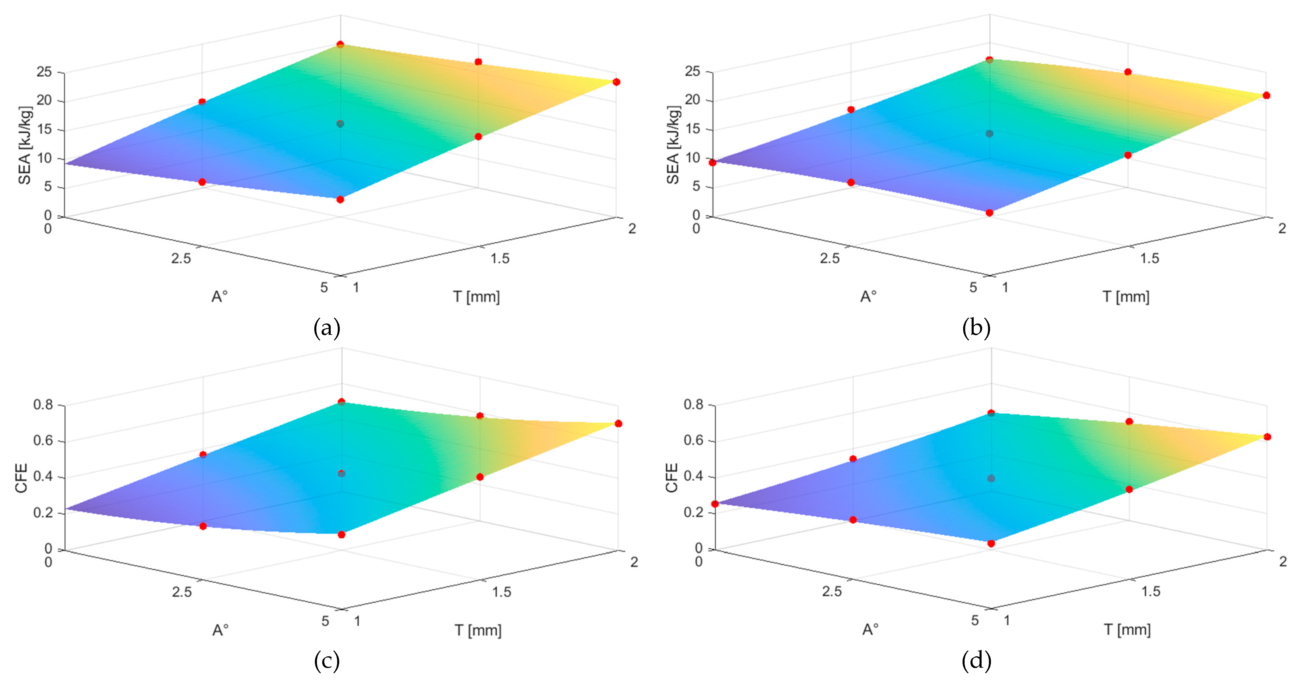
Figure 8.
Proposed design configurations after initial investigation: (a) Before compression; (b) After compression.
Figure 8.
Proposed design configurations after initial investigation: (a) Before compression; (b) After compression.
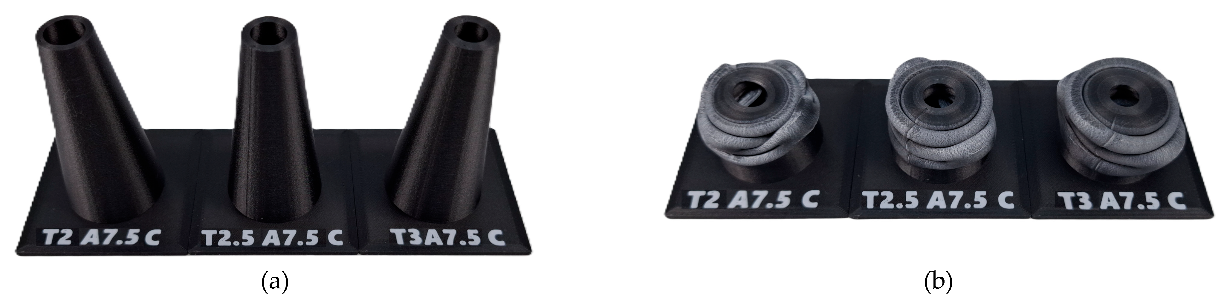
Figure 9.
Comparison of and values for tubular crash boxes manufactured using the FDM process in recent studies [17,18,23,27,30,31,36,37,38].
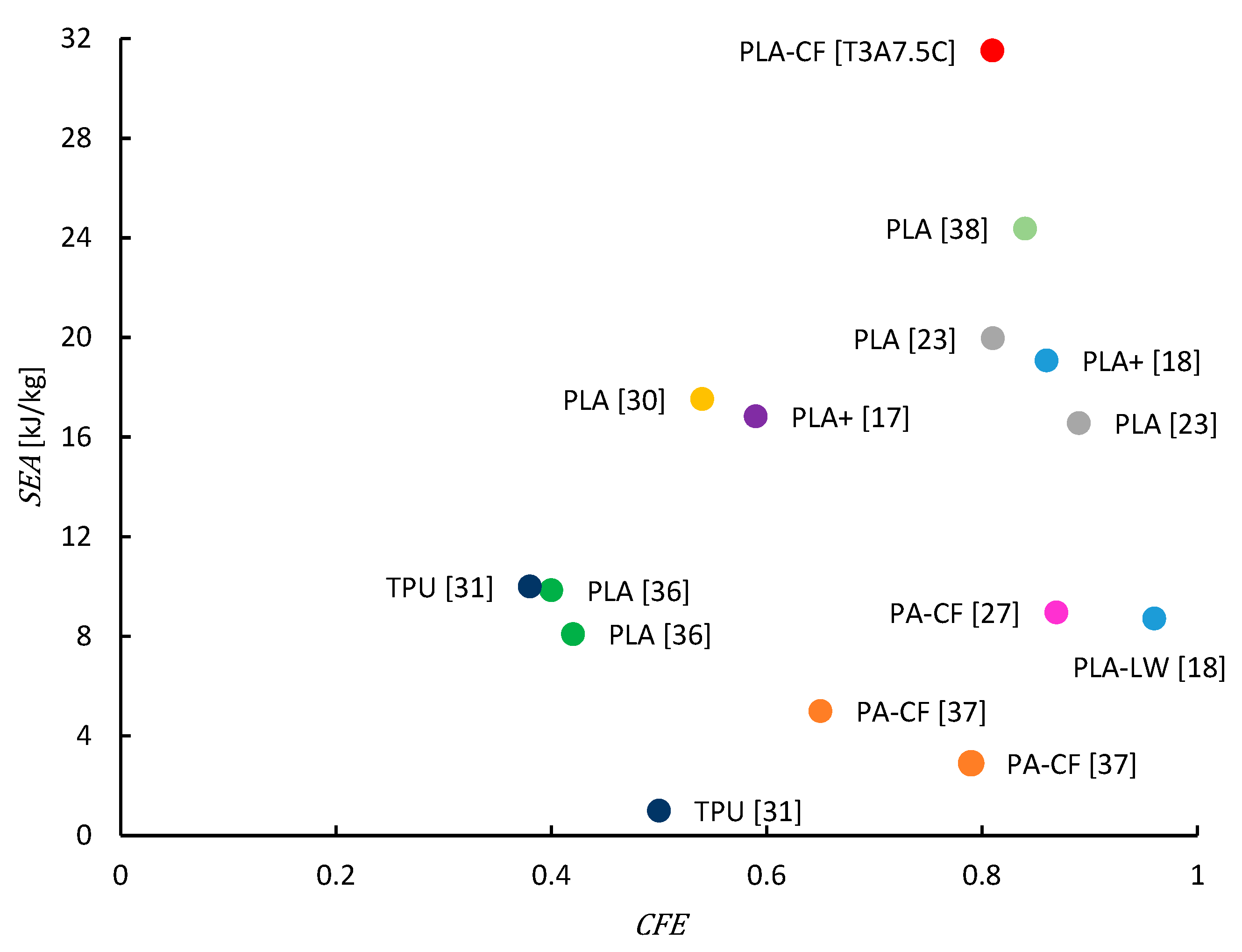

Table 1.
Mechanical properties of PLA+ and PLA-CF.
| Property | PLA+ | PLA-CF |
|---|---|---|
| Density (g/cm3) | 1.23 | 1.21 |
| Tensile Strength (MPa) | 63 | 39 |
| Elongation at Break (%) | 20 | 4.27 |
| Flexural Strength (MPa) | 74 | 103 |
| Flexural Modulus (MPa) | 1973 | 5003 |
| IZOD Impact Strength (kJ/m2) | 9 | 5.08 |
Table 2.
Printing parameters of PLA+ and PLA-CF.
| Parameter | PLA+ | PLA-CF |
|---|---|---|
| Printing temperature (⁰C) | 220 | 220 |
| Bed temperature (⁰C) | 60 | 60 |
| Diameter of nozzle (mm) | 0.4 | 0.4 |
| Layer height (mm) | 0.15 | 0.15 |
| Infill density (%) | 100 | 100 |
| Outer Wall Print speed (mm/s) | 80 | 80 |
| Inner Wall Print speed (mm/s) | 110 | 110 |
Table 3.
Crashworthiness indicators for various design configurations fabricated from PLA-CF and PLA+.
Table 3.
Crashworthiness indicators for various design configurations fabricated from PLA-CF and PLA+.
| Case | [g] | [kJ] | [kN] | [kN] | [kJ/kg] | |
|---|---|---|---|---|---|---|
| T1A0C | 6.2 | 0.007 | 6.158 | 0.172 | 1.112 | 0.028 |
| T1A2.5C | 5.6 | 0.063 | 5.268 | 1.569 | 11.205 | 0.298 |
| T1A5C | 5.1 | 0.068 | 4.084 | 1.691 | 13.260 | 0.414 |
| T1.5A0C | 9.3 | 0.139 | 9.471 | 3.466 | 14.908 | 0.366 |
| T1.5A2.5C | 8.5 | 0.138 | 8.087 | 3.443 | 16.203 | 0.426 |
| T1.5A5C | 7.6 | 0.145 | 6.358 | 3.631 | 19.110 | 0.571 |
| T2A0C | 12.2 | 0.242 | 12.155 | 6.040 | 19.803 | 0.497 |
| T2A2.5C | 11.1 | 0.243 | 10.442 | 6.073 | 21.884 | 0.582 |
| T2A5C | 10.0 | 0.235 | 8.346 | 5.875 | 23.500 | 0.704 |
| T1A0+ | 6.3 | 0.059 | 5.821 | 1.484 | 9.421 | 0.255 |
| T1A2.5+ | 5.8 | 0.064 | 4.855 | 1.605 | 11.072 | 0.331 |
| T1A5+ | 5.2 | 0.057 | 3.934 | 1.419 | 10.915 | 0.361 |
| T1.5A0+ | 9.3 | 0.125 | 9.180 | 3.135 | 13.486 | 0.342 |
| T1.5A2.5+ | 8.5 | 0.123 | 7.728 | 3.068 | 14.436 | 0.397 |
| T1.5A5+ | 7.7 | 0.122 | 6.082 | 3.042 | 15.800 | 0.500 |
| T2A0+ | 12.2 | 0.208 | 11.963 | 5.191 | 17.019 | 0.434 |
| T2A2.5+ | 11.1 | 0.222 | 10.121 | 5.557 | 20.026 | 0.549 |
| T2A5+ | 10.0 | 0.211 | 8.392 | 5.271 | 21.082 | 0.628 |
Table 4.
Error assessment of regression models for PLA-CF and PLA+.
| Material | Crashworthiness Indicator |
||
|---|---|---|---|
| PLA-CF | 0.99671 | 2.48% | |
| 0.99804 | 2.23% | ||
| PLA+ | 0.99503 | 3.53% | |
| 0.99189 | 4.97% |
Table 5.
Results for proposed design configurations.
| Case | [g] | [kJ] | [kN] | [kN] | [kJ/kg] | |
|---|---|---|---|---|---|---|
| T2A7.5C | 8.8 | 0.220 | 7.310 | 5.509 | 25.041 | 0.754 |
| T2.5A7.5C | 10.7 | 0.309 | 10.455 | 7.719 | 28.856 | 0.738 |
| T3A7.5C | 12.5 | 0.394 | 12.171 | 9.853 | 31.531 | 0.810 |
Disclaimer/Publisher’s Note: The statements, opinions and data contained in all publications are solely those of the individual author(s) and contributor(s) and not of MDPI and/or the editor(s). MDPI and/or the editor(s) disclaim responsibility for any injury to people or property resulting from any ideas, methods, instructions or products referred to in the content. |
© 2025 by the authors. Licensee MDPI, Basel, Switzerland. This article is an open access article distributed under the terms and conditions of the Creative Commons Attribution (CC BY) license (http://creativecommons.org/licenses/by/4.0/).
Copyright: This open access article is published under a Creative Commons CC BY 4.0 license, which permit the free download, distribution, and reuse, provided that the author and preprint are cited in any reuse.


