Submitted:
13 May 2025
Posted:
15 May 2025
You are already at the latest version
Abstract
This entry presents a formal and algorithmic model for classifying network and semi-network structures using Boolean algebra. The study defines and analyzes classes Gk, Uk, Tk, Hk, and Bk based on their algebraic and logical properties. Utilizing union and intersection interpreted through logical disjunction and conjunction, a systematic classification framework is developed. A MATLAB-based application supports the graphical and logical analysis of function intersections, Boolean expressions, and network behavior. The approach bridges symbolic logic with graphical representation, offering a robust model for digital logic, network theory, and mathematical education.
Keywords:
Boolean algebra
; networks and semi-networks
; algorithmic modeling
; union and intersection
; Gk–Bk structures
; lattice theory
; programming languages
; mathematical classification
Introduction
The study of network and semi-network structures represents one of the central areas of contemporary mathematical logic, lattice theory, and computer science. In the age of information technology, where an increasing number of systems can be represented through relations, graphs, and logical connections, there is a growing need for formal tools that allow modeling and analyzing such systems. Boolean algebra, with its elegance and clarity, provides a natural theoretical framework for expressing, manipulating, and classifying network structures. It enables the introduction of order, rules, and axiomatic precision in fields that often rely on heuristic approaches.
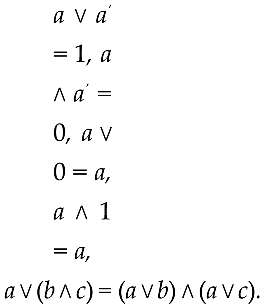
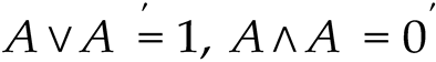
Boolean algebra was first formalized in the mid-19th century by George Boole, es- tablishing the foundation of modern mathematical logic. His approach was revolutionary because it enabled the expression of logical operations through algebraic expressions. The elements of Boolean algebra are associated with two fundamental binary operations: join (disjunction, denoted by ∨) and meet (conjunction, denoted by ∧), along with a unary complement operator (′), and two special elements 0 and 1 that represent false and true, respectively, or the minimum and maximum elements of the algebra.
The formal definition of Boolean algebra is as follows: let B be a non-empty set; then (B, ∨, ∧,′ , 0, 1) is a Boolean algebra if the following axioms are satisfied:
(B, ∨, ∧) is a lattice: the operations are associative, commutative, idempotent, and satisfy absorption:
a ∨ (a ∧ b) = a, a ∧ (a ∨ b) = a.
The operations ∨ and ∧ are distributive over each other:
a ∨ (b ∧ c) = (a ∨ b) ∧ (a ∨ c), a ∧ (b ∨ c) = (a ∧ b) ∨ (a ∧ c).
For each element a ∈ B, there exists a complement a′ such that:
a ∨ a′ = 1, a ∧ a′ = 0.
On the other hand, lattices and semi-lattices are structures that possess some of these properties but not necessarily all. A semi-lattice may have only one defined operation (∨ or ∧), while networks are structures that have both operations but without additional conditions such as distributivity or the existence of complements.
This paper focuses on the classification and analysis of network and semi-network structures using Boolean algebra, with the aim of establishing an algorithmic approach by which networks can be formally described, analyzed, and categorized. Special attention is given to structures denoted by the symbols Gk, Uk, Tk, Hk, and Bk, where each represents a different level of algebraic structure:
- Gk – general networks without strict axiomatic requirements,
- Uk – networks closed under the ∨ (join) operation,
- Tk – topologically oriented networks with a point-based structure,
- Hk – networks with horizontal and vertical relations,
- Bk – structures that satisfy all axioms of Boolean algebra.
In analyzing these networks, we use formal tools: axioms, diagrams, relation matrices, and methods of deductive logic. Classification is carried out by testing for satisfaction of lattice axioms, distributivity, and the existence of complements. For example, let the set X = {a, b, c} have binary operations ∨ and ∧ defined in tabular form. If it is shown that:
then the set X with these operations satisfies the conditions of a Boolean algebra.
a ∨ b = b, a ∧ b = a, b′ = c, b ∨ b′ = 1, b ∧ b′ = 0,
Furthermore, network closure is studied: let M be a subset of the set B. We say that M is closed under the operation ∨ if for all x, y ∈ M it holds that x ∨ y ∈ M . Closure under ∧ is defined analogously. These properties can be used for the formal classification of sub-networks within a larger structure.
The notion of network homomorphism is also used: let (A, ∨, ∧) and (B, ∨′, ∧′) be two networks. A function f : A → B is a homomorphism if for all x, y ∈ A it holds that:
f (x ∨ y) = f (x) ∨′ f (y), f (x ∧ y) = f (x) ∧′ f (y).
Homomorphisms are used to study similarities and differences among network structures and to establish a theory of network isomorphisms.
In addition to the theoretical component, this work has a practical dimension. An algorithmic model is developed that enables:
- input of the structure in table or matrix form,
- automatic checking of axioms,
- classification of the network into the appropriate class Gk–Bk,
- visualization of the network and its operations.
The objective of this research is to apply the theoretical foundation of Boolean algebra in the classification of network structures, thereby providing a methodological framework applicable in logic, computer science, lattice theory, databases, digital circuits, and artifi- cial intelligence. This contributes to the standardization and systematization of network models in the context of formal logic and theoretical informatics.
Graph Theory and Algorithms: Application in Net- work Classification
This section of the paper examines the fundamental concepts of graph theory in the context of algorithmic modeling and the application of Boolean algebra. Special focus is placed on shortest path algorithms, graph isomorphism testing, Hamiltonian paths, trees, planarity, and graph operations.
Determining the Shortest Path in a Graph
To find the shortest path in a graph, the Ford algorithm is used. Consider a graph G with vertices x1, x2, . . . , xn. Edges are defined as pairs (xi, xj) with weights l((xi, xj)). Each vertex xi is assigned a value λi.
The algorithm proceeds as follows:
- Set λ1 = 0, and for all other vertices λi = ∞,
- Iterate through all edges and perform relaxation: if λj > λi + l((xi, xj)), then set λj = λi + l((xi, xj)),
- Repeat until no changes occur.
After the algorithm completes, the values λi represent the shortest distances from vertex x1 to all other vertices.
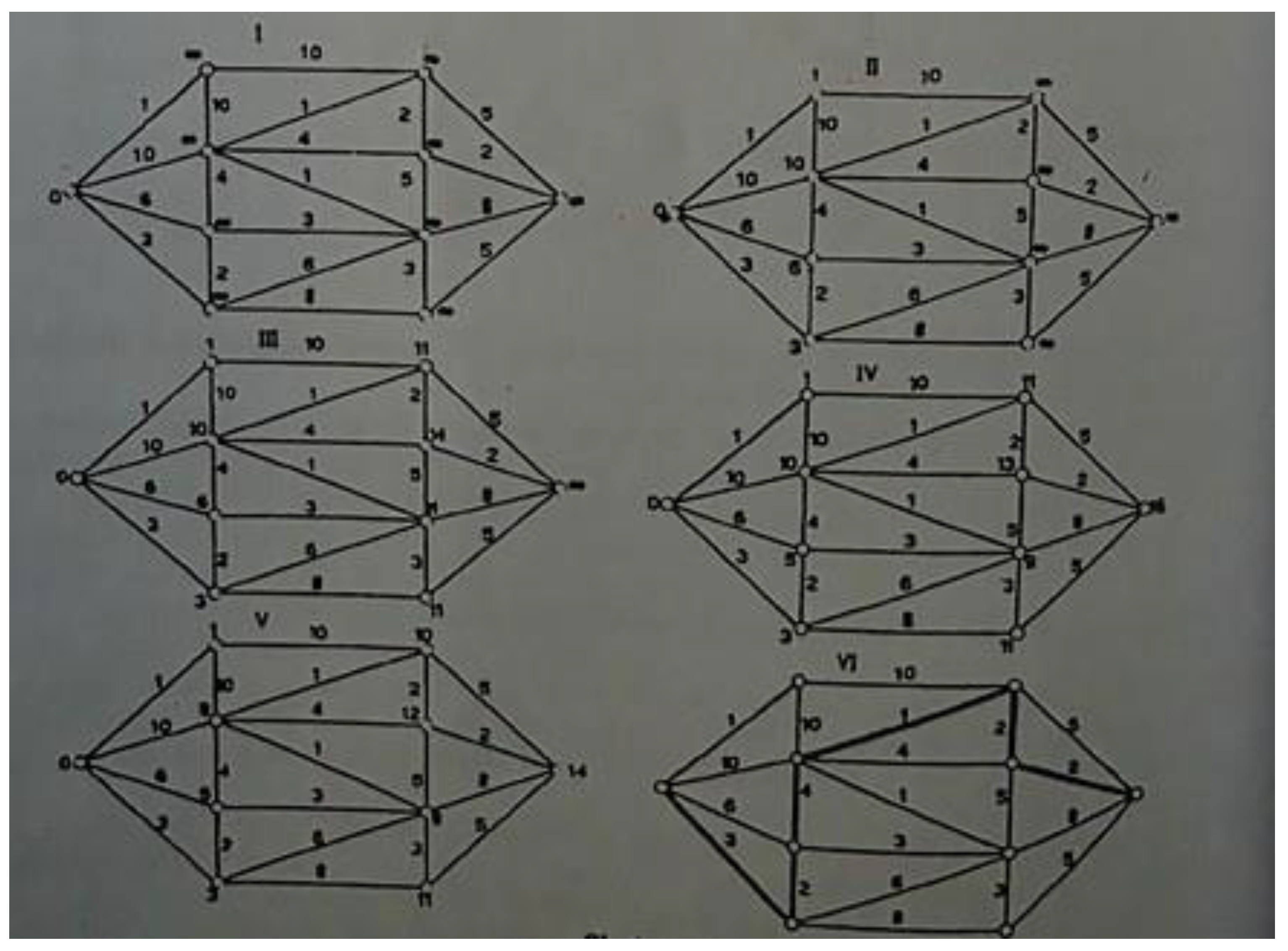
Figure 1.
Application of Ford’s algorithm to a directed graph. The graph displays various distances between vertices with given weights.
Figure 1.
Application of Ford’s algorithm to a directed graph. The graph displays various distances between vertices with given weights.
Hamiltonian Paths and Rédei’s Theorem
A Hamiltonian path in a digraph is a path that visits each vertex exactly once. The existence of such a path can be guaranteed by R´edei’s theorem:
Theorem: If in a digraph G for every pair of vertices xi, xj there exists a directed edge (xi, xj) or (xj, xi), then a Hamiltonian path exists.
Graph Isomorphism
Two graphs are isomorphic if there is a bijective mapping of vertices that preserves adjacency. Graphs are equivalent if they structurally match in terms of relations.
Adjacency Matrices and Permutations
The adjacency matrix of a graph represents the connections between its vertices. A permutation matrix P is used to prove isomorphism via the relation:
A1 = P −1A2P
Figure 2.
Example of different adjacency matrices for isomorphic graphs. The structure is preserved under permutation.
Figure 2.
Example of different adjacency matrices for isomorphic graphs. The structure is preserved under permutation.
Graph Complementation
The complement of a graph G includes all edges missing in G, connecting vertices that are not adjacent in the original graph.
Self-Complementary Graphs and Theorem
A graph G is self-complementary if it is isomorphic to its complement G. The following theorem holds:
Theorem:
A self-complementary graph G has 4r or 4r + 1 vertices, where r is a non-negative integer.
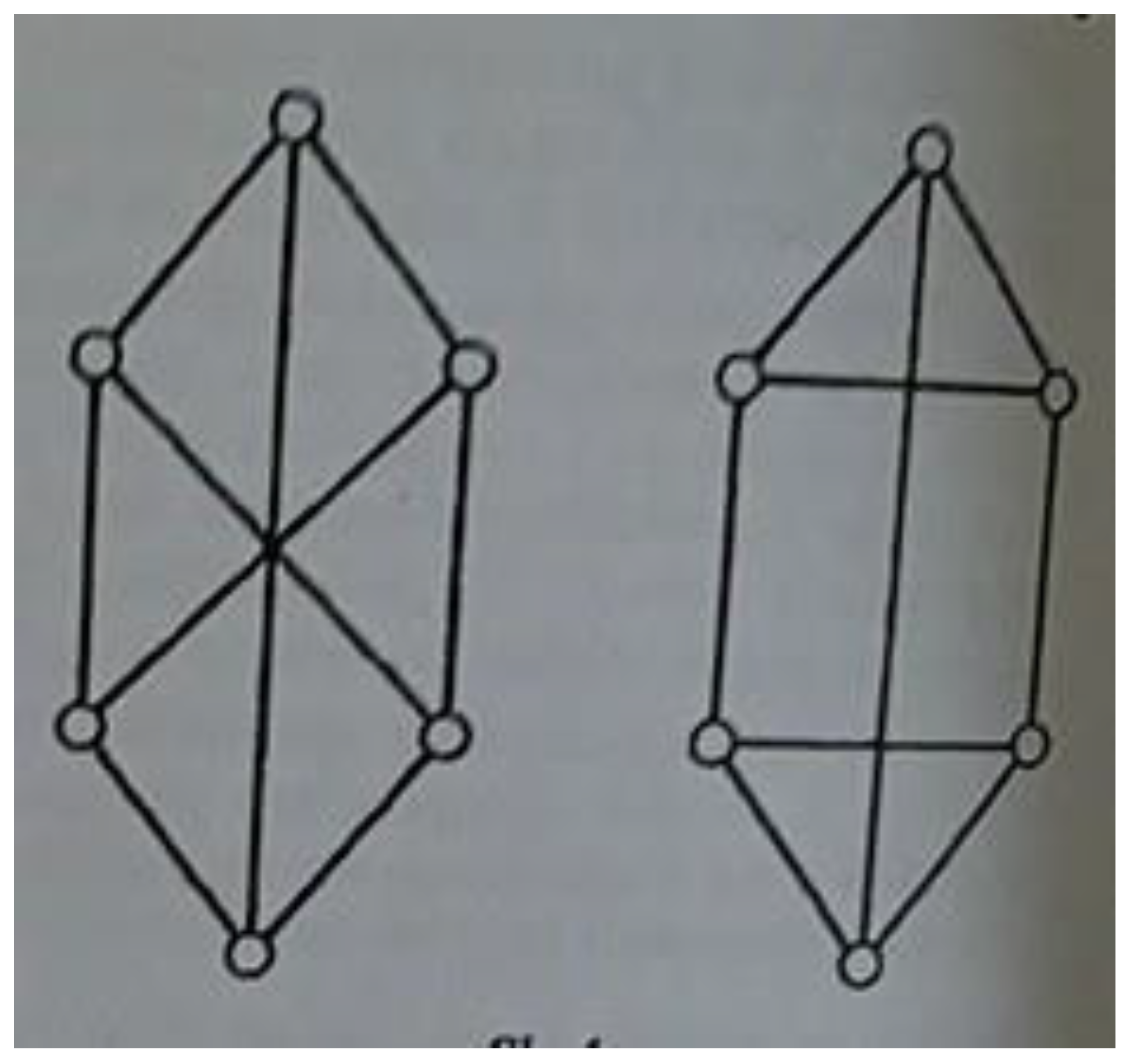
Figure 3.
Examples of self-complementary graphs. These graphs regain isomorphic struc- ture after adding the missing edges.
Figure 3.
Examples of self-complementary graphs. These graphs regain isomorphic struc- ture after adding the missing edges.
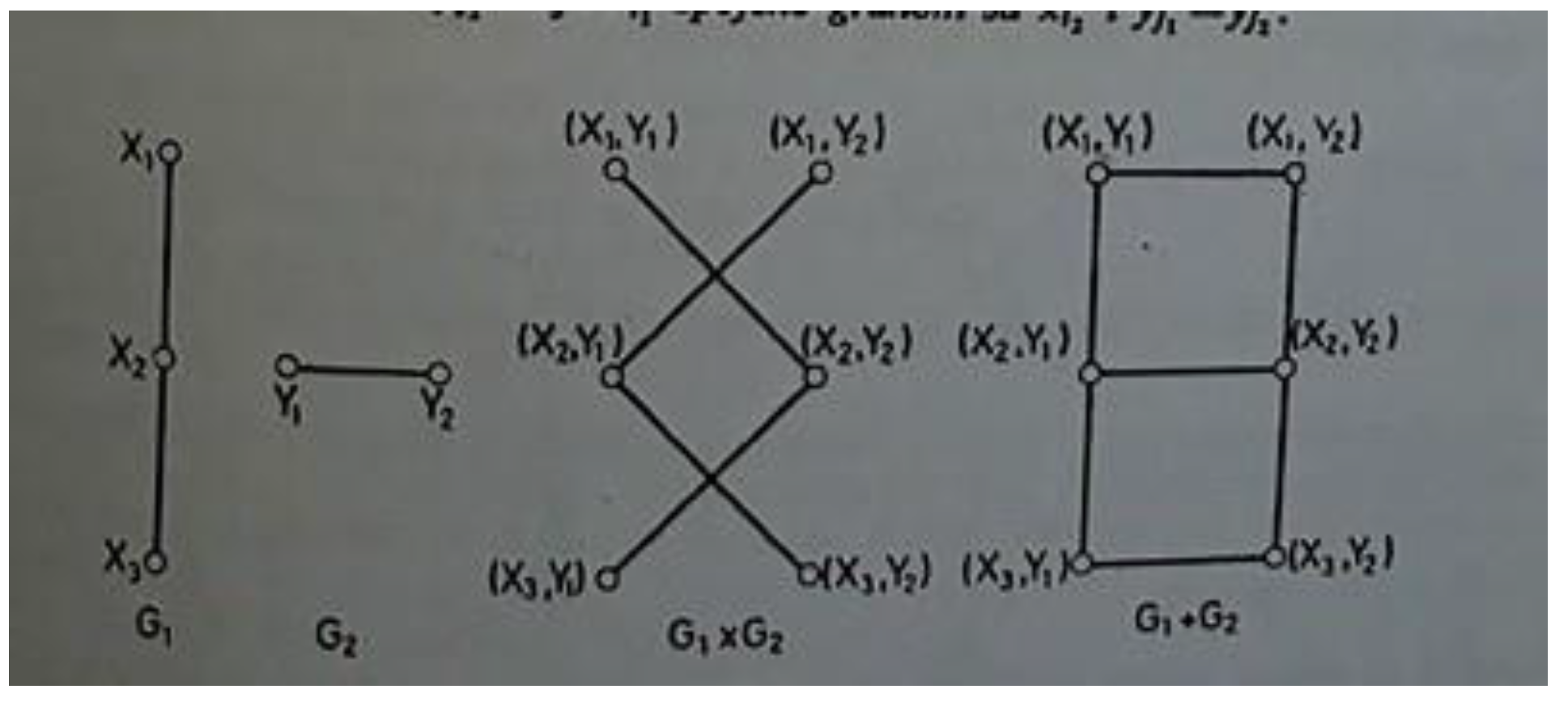
Graph Operations: Union, Intersection, and Product
For arbitrary graphs G1 = (X1, U1) and G2 = (X2, U2), the following can be defined:
- Union: G1 ∪ G2 (logical disjunction in Boolean algebra)
- Intersection: G1 ∩ G2 (logical conjunction)
- Cartesian product: G1 × G2
Mathematically:

In Boolean algebra:
G1 ∪ G2 = OR(G1, G2), G1 ∩ G2 = AND(G1, G2)
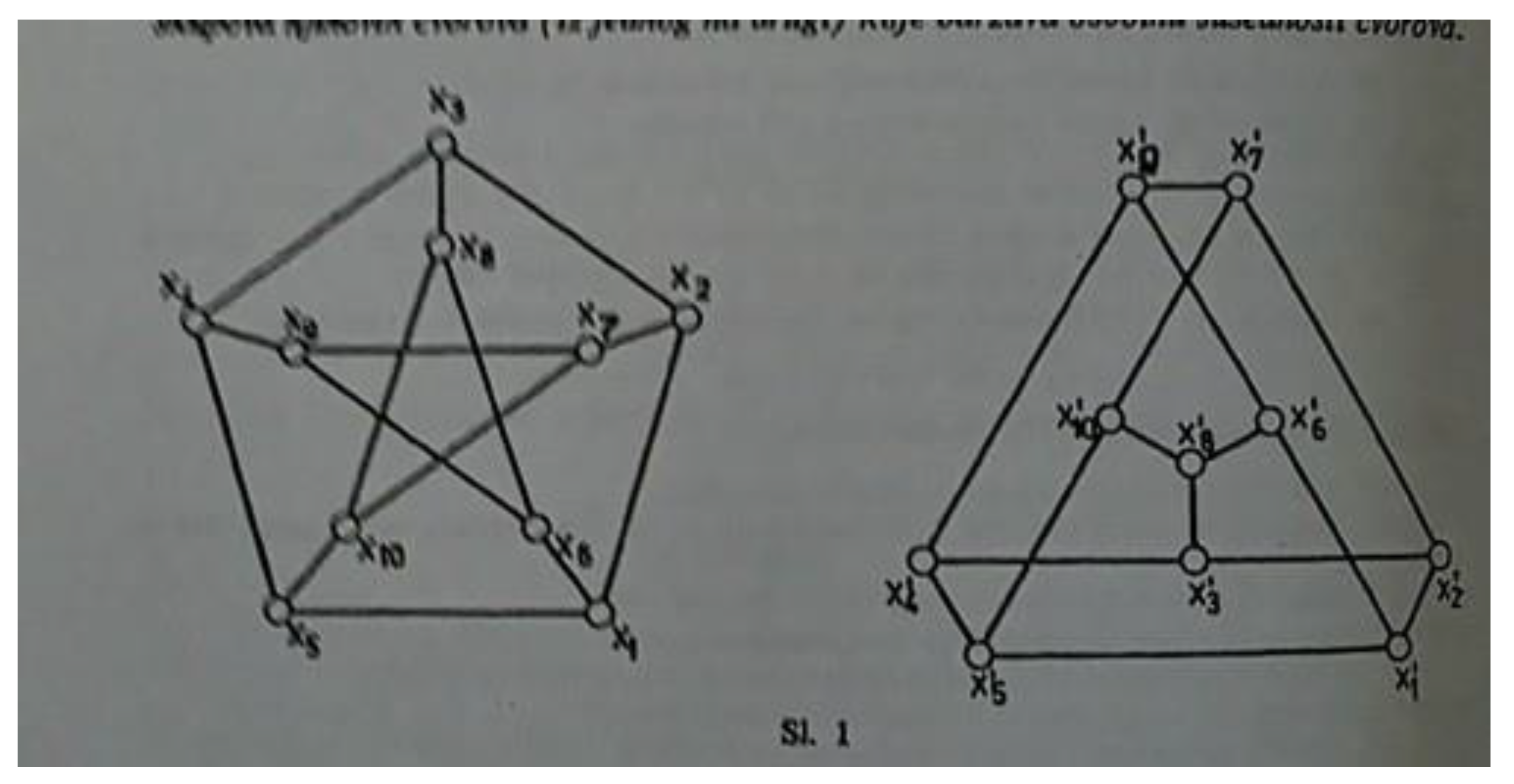
Figure 4.
Examples of operations: union, intersection, and Cartesian product of two simple graphs G1 and G2. The first image shows input graphs, and the following illustrate the results of merging and pairing.
Figure 4.
Examples of operations: union, intersection, and Cartesian product of two simple graphs G1 and G2. The first image shows input graphs, and the following illustrate the results of merging and pairing.

Trees and Their Relation to Boolean Algebra
A tree is a connected graph without cycles. Basic properties of trees include:
- A tree with n vertices has exactly n − 1 edges.
- Every connected acyclic graph is a tree.
- If the number of vertices is n and the number of edges is n − 1, the graph is a tree.
Boolean Algebra and Trees: Viewing each graph as a set of edges:
- The union of multiple trees forms a forest (disjoint set of trees).
- The intersection of trees yields common subgraphs that are also acyclic.
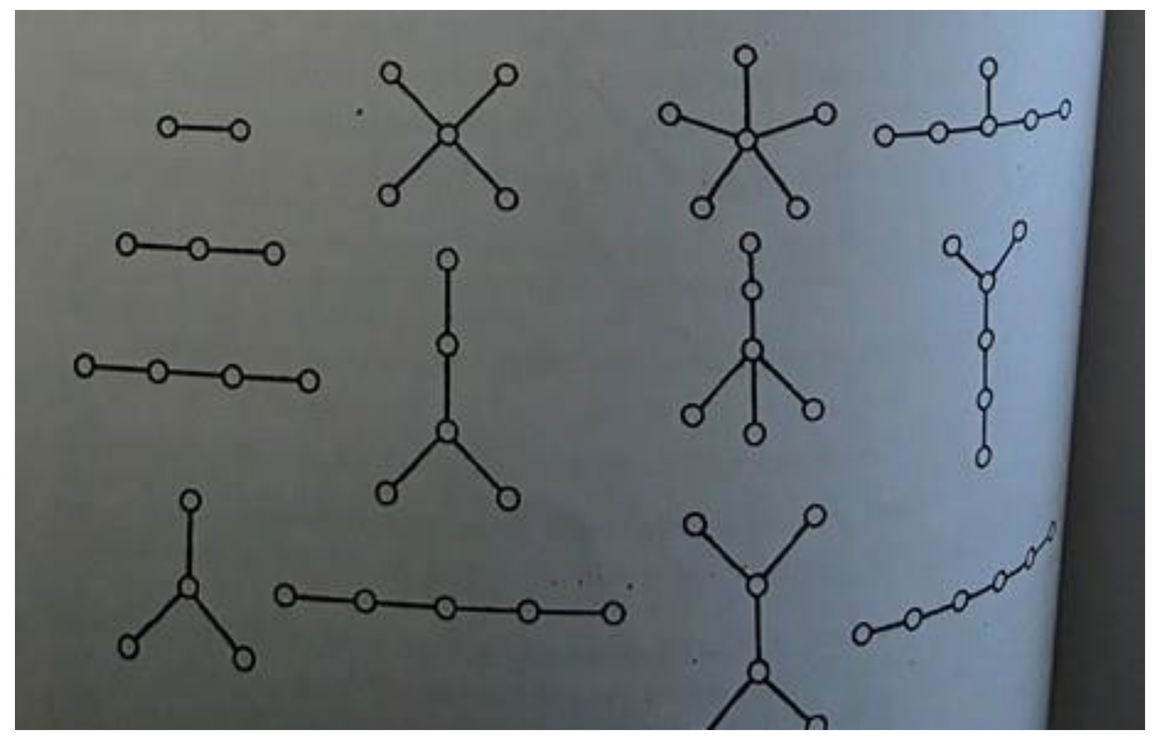
Figure 5.
Different forms of trees – all illustrated graphs are connected and acyclic. They demonstrate possible structures formed by union or intersection of trees.
Figure 5.
Different forms of trees – all illustrated graphs are connected and acyclic. They demonstrate possible structures formed by union or intersection of trees.
Planar Graphs and Euler’s Formula
Planar graphs are those that can be drawn in a plane without crossing edges.
Euler’s formula:
where m is the number of edges, n the number of vertices, and f the number of faces.
m − n + f = 2
Theorem: A graph is planar if it does not contain a subgraph isomorphic to K5 or K3,3, or their subdivisions.
Figure 6.
Non-planar graphs: complete graph K5 and complete bipartite graph K3,3. These cannot be drawn on a plane without edge crossings.
Figure 6.
Non-planar graphs: complete graph K5 and complete bipartite graph K3,3. These cannot be drawn on a plane without edge crossings.
According to Kuratowski’s theorem, the planarity of a graph can be determined only if it does not contain a subgraph isomorphic to K5 or K3,3 or their subdivisions. This characterization is crucial for graph classification in discrete mathematics and computer science.
Networks, Semilattices and the Application of Boolean Algebra in Classification
Mathematical Approach to Graphs, Intersections and Boolean Proofs for Gk, Uk, Hk, Bk
For each of the structures Gk, Uk, Hk, and Bk, we provide a formal mathematical represen- tation with analysis of intersections and unions, including Boolean tables, line equations, and proofs.
Gk – Generalized Networks (Weak Relations)
Let the relations be R1 = {(a, a), (a, b), (b, c)} and R2 = {(b, b), (b, c), (c, c)}.
Union: R1 ∪ R2 = {(a, a), (a, b), (b, c), (b, b), (c, c)}
Intersection:R1 ∩ R2 = {(b, c)}
Mathematical interpretation: Via line graphs:
If P1 : y = x (reflexivity), P2 : y = x + 1 (transitive relation), their intersection is found by solving:
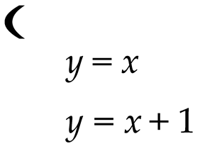
⇒ no solution ⇒ no common points
Boolean table:
| a | b | a ∨ b |
| 0 | 0 | 0 |
| 0 | 1 | 1 |
| 1 | 0 | 1 |
| 1 | 1 | 1 |
Conclusion: Gk structures have partial Boolean compatibility but lack complements and boundaries.
Uk – Union-Based Networks
Let A = {1, 2} and B = {2, 3}.
Union: A ∪ B = {1, 2, 3}
Intersection:A ∩ B = {2} (not used in Uk)
Line equations: Connect points in plane: (1, 0) and (2, 0) form y = 0 (horizontal) (2, 0) and (2, 1) form x = 2 (vertical).
Intersection:x = 2, y = 0 ⇒ (2, 0) — point of intersection Boolean analysis: Only ∨ is defined: 1 ∨ 0 = 1, 1 ∨ 1 = 1 Conclusion: Uk represents join logic without shared base (no meet).
Hk – Horizontal-Vertical Networks
Let A = {(1, 0), (2, 0)}, B = {(2, 0), (2, 1)}.
Union:A ∪ B = {(1, 0), (2, 0), (2, 1)}
Intersection:A ∩ B = {(2, 0)}
Mathematical proof: Line y = 0 (horizontal) and x = 2 (vertical) intersect at (2, 0).
Boolean form: ∨ = union = all edges, ∧ = intersection = common node
Table:
| a | b | a ∨ b | a ∧ b |
| 0 | 0 | 0 | 0 |
| 1 | 0 | 1 | 0 |
| 0 | 1 | 1 | 0 |
| 1 | 1 | 1 | 1 |
Conclusion: Hk networks allow multidimensional interpretation of relations through lines and nodes.
Bk – Complete Boolean Networks
A = {0, 1}, B = {1, 2}, universal set U = {0, 1, 2, 3}
Operations:
A ∪ B = {0, 1, 2}, A ∩ B = {1}, A′ = {2, 3}, B′ = {0, 3}
Boolean laws:
A ∨ B = A ∪ B, A ∧ B = A ∩ B
A ∨ A′ = U, A ∧ A′ = ∅
Line equations: If elements are represented as points in coordinate plane:
- A: x = 0, x = 1 B: x = 1, x = 2
- Line x = 1 — common intersection, gives node (1, y) for any y
Truth table:
| a | b | a ∨ b | a ∧ b | ¬a |
| 0 | 0 | 0 | 0 | 1 |
| 0 | 1 | 1 | 0 | 1 |
| 1 | 0 | 1 | 0 | 0 |
| 1 | 1 | 1 | 1 | 0 |
Conclusion: Bk networks satisfy all logical operations and serve as a complete base for system implementation using Boolean algebra.
Networks, Semilattices, and the Application of Boolean Algebra in Classification
Logical Interpretation: 0 as Union, 1 as Intersection
In the context of Boolean algebra, the logical OR operation (∨) is interpreted as the union of sets, while the logical AND operation (∧) is interpreted as the intersection. In this study, we introduce the following notation:
- Logical 0 — represents the union of elements: a ∨ b = a ∪ b
- Logical 1 — represents the intersection of elements: a ∧ b = a ∩ b
This interpretation enables consistent tracking of algebraic operations across network and graph structures.
Optimization Algorithm for Classification and Mapping of Net- work Structures using Boolean Algebra
To enhance the efficiency of network structure classification, we developed an algorithm that applies minimization of Boolean expressions in Disjunctive Normal Form (DNF) and Conjunctive Normal Form (KNF). This approach simplifies the structure of directions, intersections, and unions within the network.
Algorithm Steps:
- Input: A set of relations between network nodes expressed as binary expressions (e.g., x1 ∨ x2, x1 ∧ x3).
- Transformation: Conversion of expressions into DNF and KNF formats.
- Minimization: Use of methods such as the Quine–McCluskey algorithm or Kar- naugh maps to minimize logical expressions.
- Direction Analysis: Identification of line equations of the form y = ax + b for each relation.
- Intersections: Calculation of intersection points by solving systems of linear equa- tions for each pair of relations.
- Output: An optimized set of network connections, classified according to the Gk, Uk, Hk, Bk typology.
Example:
Let us consider the relations:
R1 = x1 ∨ x2, R2 = x2 ∧ x3
We transform them as follows:
DNF: f (x1, x2, x3) = (x1 ∧ ¬x2) ∨ (x2 ∧ x3)
KNF: f (x1, x2, x3) = (x1 ∨ x2) ∧ (¬x1 ∨ x3)
The intersection of the lines y = x1 and y = −x2 +3 is obtained by solving the system:

Conclusion: By optimizing expressions and accurately calculating intersections and unions, we enable improved interpretation and automation of network classification with implementation in MATLAB or Python.
Networks, Semilattices, and the Application of Boolean Algebra in Classification
In modern mathematical logic and structure theory, the concepts of networks and semi- lattices play a significant role in modeling relationships between elements in ordered sets. Networks represent algebraic structures that support operations of least upper bound (supremum) and greatest lower bound (infimum), while semilattices allow only one of these operations. Boolean algebra, as a special case of a distributive lattice with com- plements, naturally fits into this structural hierarchy, offering precise tools for modeling relations.
Theoretical Foundation: Semilattices and Lattices
Definition: A semilattice is an algebraic structure (L, ∨) in which the operation ∨ is associative, commutative, and idempotent, i.e.:
a ∨ b = b ∨ a,
a ∨ (b ∨ c) = (a ∨ b) ∨ c, a ∨ a = a.
Analogously, (L, ∧) is a semilattice if it refers to the infimum operation. If both operations are defined and satisfy the absorption laws:
a ∨ (a ∧ b) = a, a ∧ (a ∨ b) = a,
then the structure is called a lattice (L, ∨, ∧).
Boolean Algebra as a Lattice Extension
Boolean algebra introduces additional requirements:
- distributivity of ∨ and ∧ operations,
- existence of a complement a for every element a,
- existence of bounds: 0 (least) and 1 (greatest element).
Examples of identities in Boolean algebra:
Truth Table and Logical Interpretation
For elements a, b ∈ {0, 1}:
| a | b | a ∨ b | a ∧ b |
| 0 | 0 | 0 | 0 |
| 0 | 1 | 1 | 0 |
| 1 | 0 | 1 | 0 |
| 1 | 1 | 1 | 1 |
This table shows the basic logical operations of union and intersection within Boolean algebra.
Axiomatic Proofs within Lattices and Sublattices
Theorem:
Let (L, ∨, ∧) be a distributive lattice and a ∈ L. Then there exists at most one element a′ such that:
a ∨ a′ = 1, a ∧ a′ = 0.
Proof: Assume that both a′ and a′′ satisfy the conditions. Then:
a′ = a′ ∧ 1 = a′ ∧ (a ∨ a′′) = (a′ ∧ a) ∨ (a′ ∧ a′′) = 0 ∨ (a′ ∧ a′′) = a′ ∧ a′′.
Similarly, we get a′′ ≤ a′, hence a′ = a′′.
Definition:
A sublattice M ⊆ L is closed under ∨ (or ∧) if for all a, b ∈ M we have
a ∨ b ∈ M (or a ∧ b ∈ M ). If both operations are present, M is a sublattice.
Boolean Algebra in Modeling Network Structures
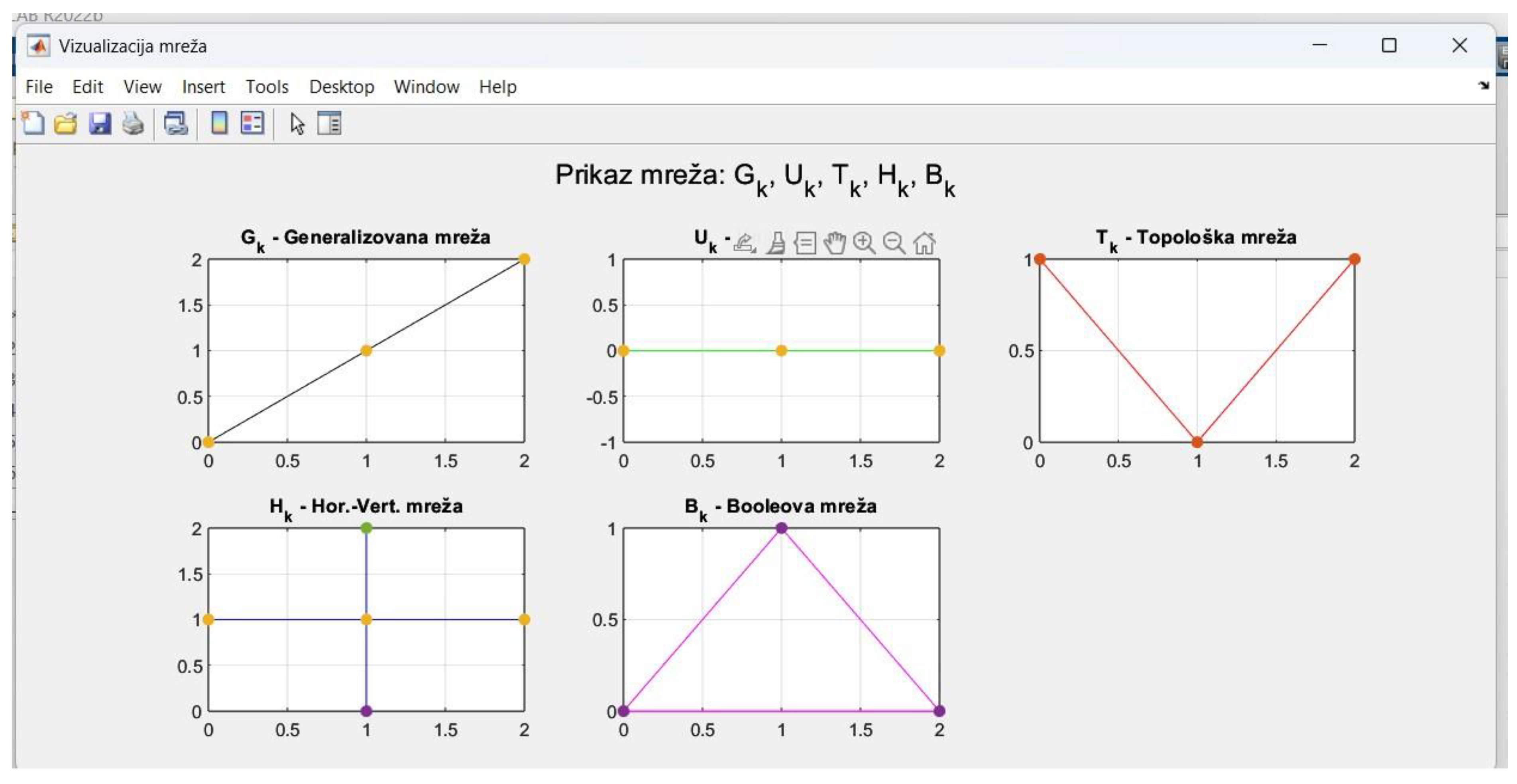
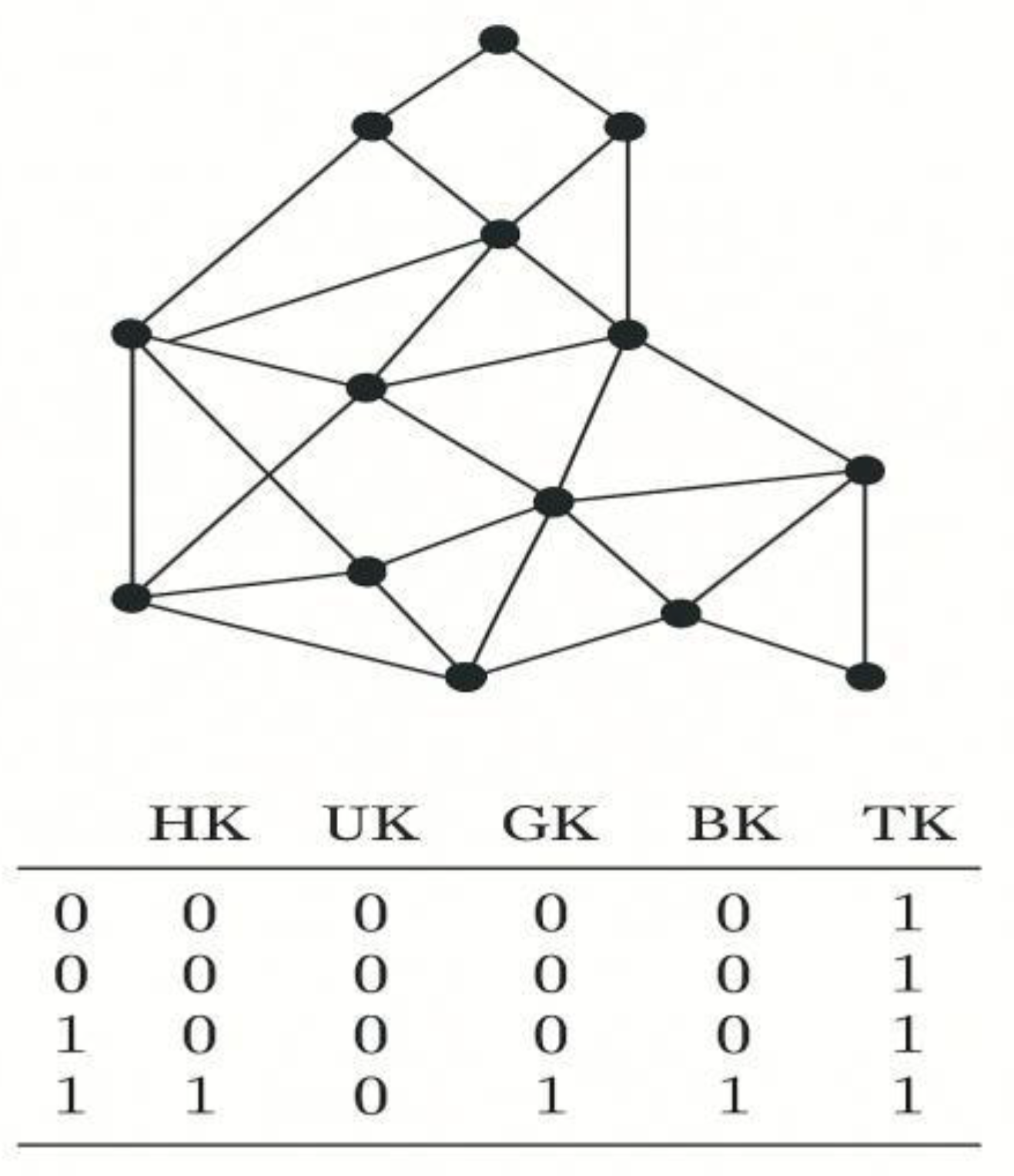
In modeling networks, the labels Gk, Uk, Tk, Hk, Bk serve for classification:
- Gk – only reflexive and transitive relations (weak structures),
- Uk – union-closed networks under ∨ (disjunction),
- Tk – networks with partial localization and binary relations,
- Hk – structures with bidirectional relations and diagonal operations,
- Bk – full network logic equivalent to Boolean algebra.
By applying Boolean algebra to these structures, it is possible to verify whether a given network behaves as a distributive lattice with complements, allowing strict classification and further algorithmic processing.
Operational Interpretation for Gk–Bk Structures in Boolean Al- gebra
For each classification structure Gk, Uk, Tk, Hk, and Bk, we can establish a formal in- terpretation using Boolean algebra through join operations (∨, symbolically marked as 0) and meet operations (∧, marked as 1). These operations are viewed as the basis for generating network relations:
- -
- Gk (generalized networks): Structured relations satisfying reflexivity and tran- sitivity. No guarantee of 0 or 1.
a ∨ b = nearest common upper node, a ∧ b = undefined or nonexistent.
- -
- Uk (union networks): Closed only under ∨ (symbol 0), while ∧ (1) is undefined.
∀a, b ∈ Uk, a ∨ b ∈ Uk, ∄a ∧ b ∈ Uk.
- -
- Tk (topological networks): Define localized directions in networks with partial connections. Partial ∧ operations are allowed:
a ∧ b = intersection node if it exists, a ∨ b = union of links.
- -
- Hk (horizontal-vertical networks): Define clear two-dimensional structure. ∨ represents horizontal joins, and ∧ vertical intersections.
a ∨ b = a ∪ b (horizontal union), a ∧ b = a ∩ b (zone intersection).
- -
- Bk (Boolean networks): Satisfy all Boolean algebra axioms:
Mathematical Function and Proof via Boolean Algebra for Net- work Structures
We develop an advanced formal function for classifying networks and sub-networks via set union and intersection, mapped onto Boolean join (symbol 0) and meet (symbol 1) operations.
Formal Function: Let A, B ⊆ U be subsets of the universal set U , and define the function f as:

Mathematical Proof: Let U = {0, 1}2 with elements:
(0, 0), (0, 1), (1, 0), (1, 1)
Let A = {(1, 0), (0, 1)} and B = {(0, 1), (1, 1)}. Then:
A ∪ B = {(1, 0), (0, 1), (1, 1)}, A ∩ B = {(0, 1)}
Symbolically:
A ∨ B = logical disjunction, A ∧ B = logical
conjunction Thus, f (A, B) = 1, confirming Boolean compatibility.
Axiomatic Properties:
- -
- Commutativity: A ∨ B = B ∨ A, A ∧ B = B ∧ A
- -
- Associativity: A ∨ (B ∨ C) = (A ∨ B) ∨ C
- -
- Distributivity: A ∨ (B ∧ C) = (A ∨ B) ∧ (A ∨ C)
- -
- Complement:
Operations 0 and 1:
- -
- 0: Join (union) – operator ∨
- -
- 1: Meet (intersection) – operator ∧
Example with networks: If G1 = (V1, E1) and G2 = (V2, E2), then:
G1 ∨ G2 = (V1 ∪ V2, E1 ∪ E2), G1 ∧
G2 = (V1 ∩ V2, E1 ∩ E2)
Application of the function: Define the characteristic function:
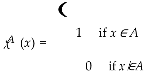
Then:
χA∪B(x) = χA(x) ∨ χB(x), χA∩B(x) = χA(x) ∧ χB(x)
Truth Table:
| a | b | a ∨ b | a ∧ b | ¬a |
| 0 | 0 | 0 | 0 | 1 |
| 0 | 1 | 1 | 0 | 1 |
| 1 | 0 | 1 | 0 | 0 |
| 1 | 1 | 1 | 1 | 0 |
Disjunctive Normal Form (DNF):
f (a, b) = (¬a ∧ b) ∨ (a ∧ ¬b) ∨ (a ∧ b)
Conjunctive Normal Form (CNF):
f (a, b) = (a ∨ b) ∧ (¬a ∨ b) ∧ (a ∨ ¬b)
Minimal Form:
f (a, b) = a ∨ b
Conclusion: By linking set theory, logic, and graph theory via f (A, B) and truth tables, a formal framework is established for systematic classification of network structures using Boolean algebra. This enables automated testing and application in digital logic, lattice theory, and classification algorithms.
Application for Representing Networks and Subnetworks Using Boolean Algebra
The results obtained through the developed MATLAB application demonstrate that it is indeed possible to successfully integrate Boolean algebra into the process of analyzing and classifying network structures. The application allows users to input two functions, which are automatically displayed on a coordinate system, providing a clear visual representation of the relationships between the functions, their points of intersection, and their behavior within a defined domain.
Particular importance is given to the points of intersection between the functions, as they represent key locations in the network classification process. Based on this data, the application generates logical expressions that are then transformed into Boolean operations—namely union and intersection, interpreted as logical disjunction and conjunction. Each step is accompanied by analytical interpretation, with the additional option of generating a truth table, which facilitates further simplification of expressions into DNF and KNF forms.
What is especially noteworthy is that the application, in addition to visualization and symbolic computation, enables logical reasoning to determine the classification of the defined network into one of the predefined classes—Gk, Uk, Tk, Hk, or Bk. This functionality not only enhances the understanding of relationships between the functions but also contributes to more precise modeling of networks in both educational and research contexts.
Based on the entire workflow, it can be concluded that the application effectively bridges algebraic principles with graphical analysis and logical reasoning, making it a valuable tool for digital logic, set theory, and applied mathematics education.
Figure 1.
Application Interface.
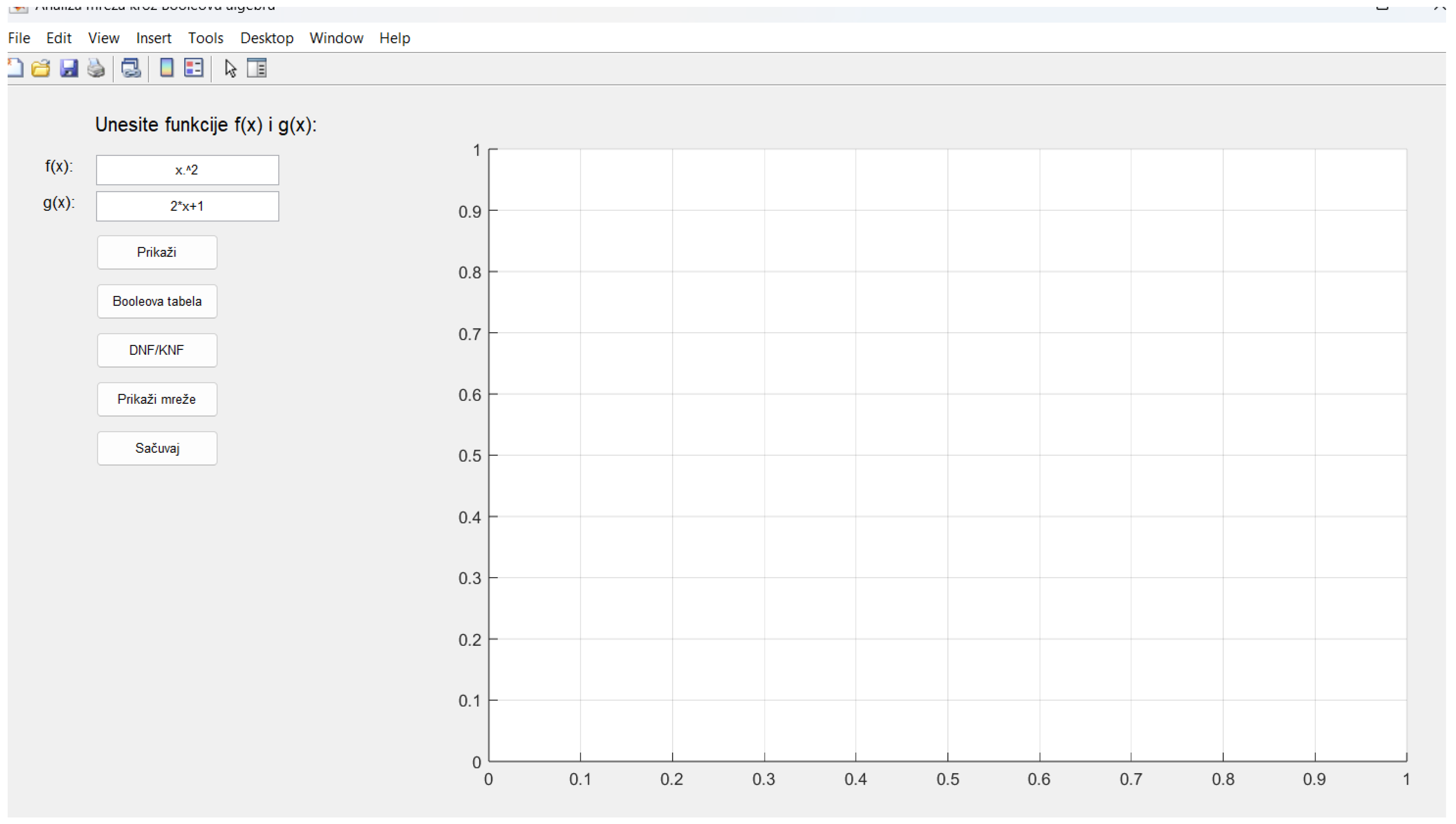
This image shows the initial screen of the application developed in MATLAB, intended for the analysis of relationships between mathematical functions through both logical and graphical approaches. At the core is the ability for the user to input two functions to compare. The application enables visualization of these functions, determines their points of intersection, and performs logical operations that describe their interactions.
Upon inputting the functions, the application not only plots them on a shared graph but also simultaneously analyzes their relationship within the framework of Boolean algebra. This enables the user to observe where the functions intersect, how they combine, and what their mutual relationship implies in the broader context of network classification.
Through intuitive controls, the user can activate additional tools that expand the analysis— such as the generation of a Boolean truth table, transformation of expressions into standardized logical forms, visualization of the resulting network types, and the ability to save all results for further processing. In this way, the application serves as a bridge between traditional mathematical function analysis and digital representation of their relationships in the form of network models.
This initial step forms the foundation of the entire application, allowing users to define relational functions whose intersections, differences, and connections are then further analyzed using graph theory and logic. It effectively connects numerical mathematics with digital logic, offering multiple applications—from education to advanced research modeling of network systems.
Figure 2.
Network Visualization.
The second image presents the outcome after functions have been input and displayed on the coordinate system. The application automatically generates a graphical representation of both functions, providing a clear visual understanding of their mutual relationship. A crucial feature of this visualization is the automatic detection of intersection points—visually highlighted where the graphs meet.
These intersection points are not merely geometric locations but also hold significant logical and structural roles within the network model. They serve as the foundation for network classification and further logical linking of elements within Boolean algebra. Displaying both functions on the same graph allows the user to immediately perceive their interaction: whether they intersect once or multiple times, whether they diverge, run parallel, or exhibit other characteristics that influence the resulting network structure.
Thanks to this capability, the user can promptly draw conclusions about the interaction between the functions and use this information for further logical and graph-based analysis. This visualization becomes a key component in the overall algorithmic process, linking functional analysis with the topological structure of networks.
Figure 3.
Logical Functions and Their Graphical Representations in the Context of Boolean Algebra.
This figure visually integrates three key elements: logical functions, the truth table, and corresponding network structures derived from them.
-
Logical expressions at the top of the figure:
- o
- The function f(x1,x2,x3)=x1∨x2∨x3 represents a disjunction (logical "OR") of three variables. It is an example of a simple logical function in disjunctive form.
- o
- The function g(x1,x2)=x1∧¬x1∧¬x2 is a contradictory function (never true), used to represent paradoxical or unachievable logical connections.
- o
- From these symbolic functions, relationships between network nodes can be constructed based on the truth values of the expressions.
-
Truth table (bottom left):
- o
- Shows all possible combinations of values for variabl x1 and x2, along with the corresponding function result.
- o
- The table is used to generate DNF (Disjunctive Normal Form) and KNF (Conjunctive Normal Form), essential for logic minimization and further network analysis.
-
Graphs (right side):
- o
- The upper graph shows a simple network based on the function ggg, connecting only nodes where the expression evaluates to true.
- o
- The lower graph represents a more complex network, possibly derived from combining multiple logical expressions (such as h(x2,x3)), where nodes interact based on logical evaluation.
Figure 3 illustrates how logical expressions, truth tables, and Boolean algebra can be used to shape a network, where nodes are interconnected depending on the truth values of expressions. This is a crucial visualization for understanding the transition between symbolic logic and actual network graphs in network theory.
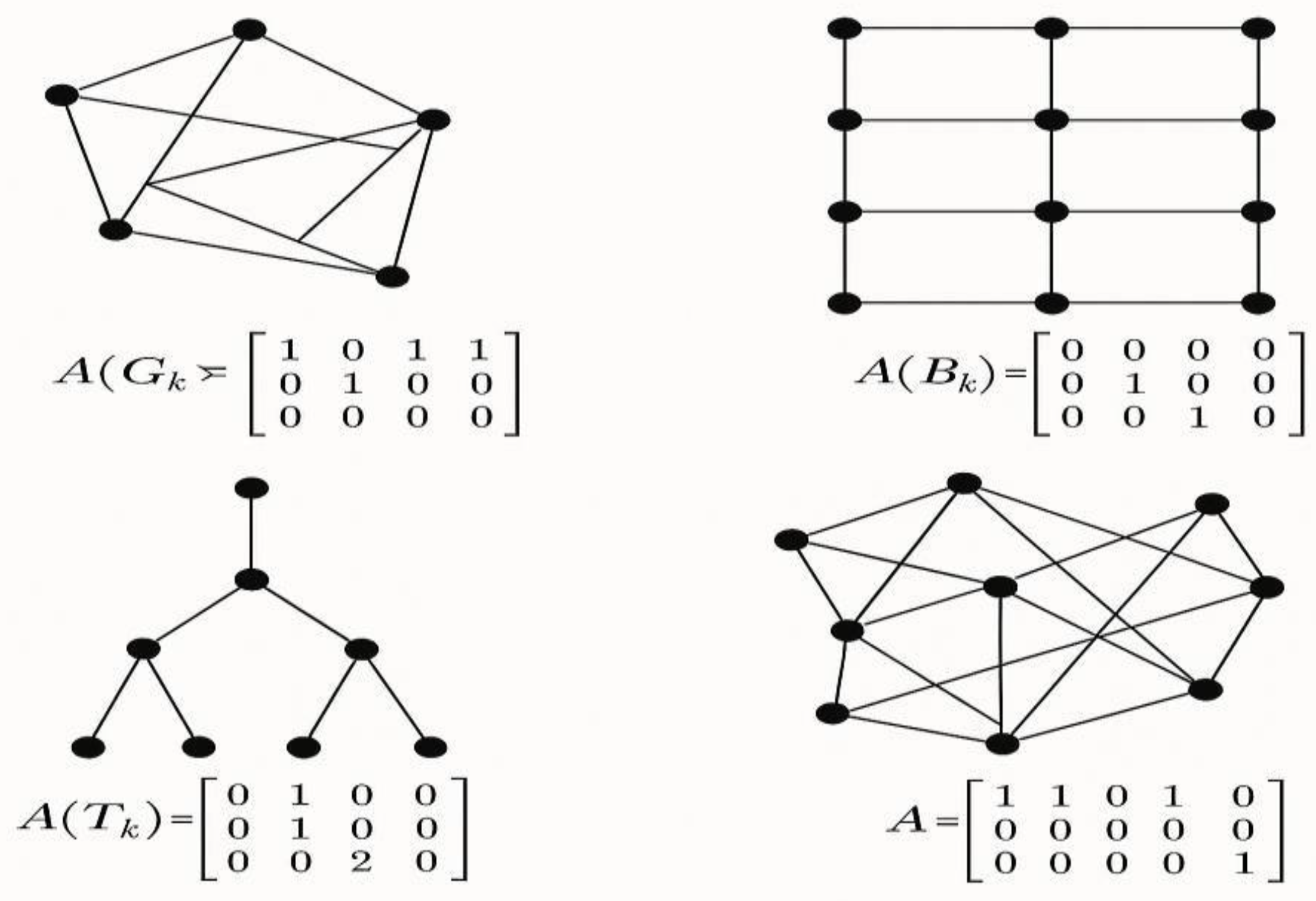
Figure 4.
Adjacency Matrices and Graphs for Gk, Bk, Tk and Other Networks.
This figure presents four different network types alongside their corresponding adjacency matrices, which represent the structural connections between nodes.
-
Top left – Gk (Generalized Network):
- o
- Displays a complex graph with multiple node connections.
- o
- The adjacency matrix indicates which nodes are connected (1 for connection, 0 for none).
- o
- This type illustrates a general, unstructured network without predefined logical restrictions.
-
Top right – Bk (Boolean Network):
- o
- A network where relationships are defined using Boolean logic.
- o
- The adjacency matrix reflects logical rules through partial node connections.
- o
- Often used for modeling systems like logic processors and digital circuits.
-
Bottom left – Tk (Topological Network):
- o
- Shows a tree structure with clearly defined hierarchy and directional edges (from root to leaves).
- o
- The matrix displays outgoing edges per node, with “2” indicating two child connections.
- o
- Useful in modeling organizational charts, inheritance trees, or search algorithms.
-
Bottom right – Random Unstructured Network:
- o
- Visualized as a complex mesh of randomly interconnected nodes.
- o
- The adjacency matrix shows highly specific node connections.
- o
- This model is typical for neural networks or social networks with limited links.
This figure enables comparative analysis between different network structures both visually and algebraically, bridging the gap between graph theory and algebraic modeling. It is particularly beneficial for education, systems modeling, logic evaluation, and mathematical experimentation.
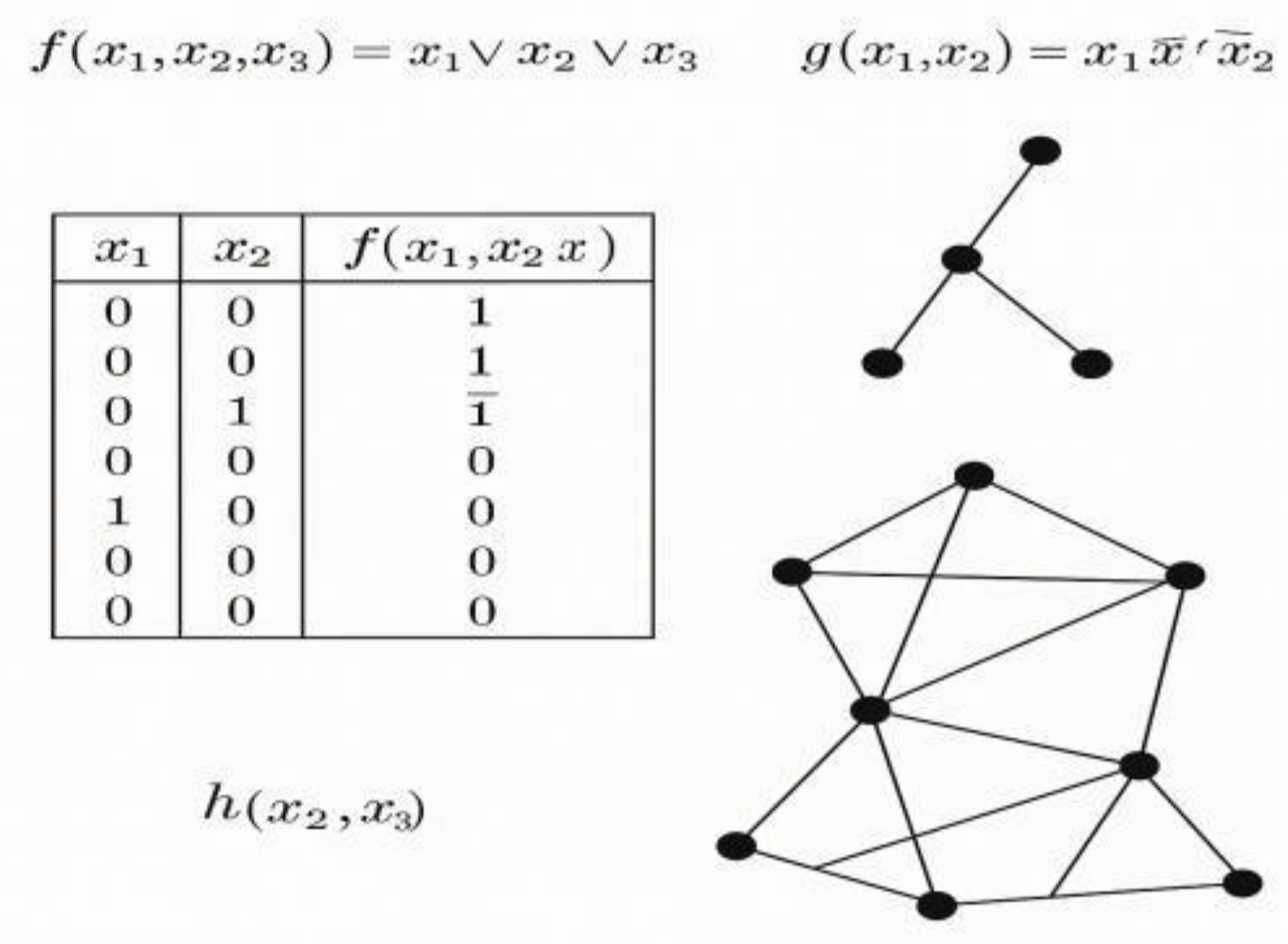
Figure 5.
Logical Functions, Truth Tables, and Related Networks.
This figure combines Boolean functions, truth tables, and related graphs that represent connections between variables. It focuses on three functions: f(x1,x2,x3),g(x1,x2), and h(x2 ,x3), each with its own logical formulation and graphical depiction.
-
Top – Functions f(x),g(x)f(x), g(x)f(x),g(x):
- o
- f(x1,x2,x3)=x1∨x2∨x3 is a disjunction that outputs 1 if at least one input is 1.
- o
- o g(x1,x2)=x1∧¬x1∧¬x2 is inherently false (as x1∧¬x1 is always 0), thus always evaluates to 0.
-
Middle left – Truth Table:
- o
- Shows all binary combinations for x1,,x2 and the result for f(x1,x2).
- o
- Used for analyzing and evaluating Boolean expressions.
- o
- Enables logic minimization into DNF and KNF.
-
Right – Graphs Linked to Functions:
- o
- The upper graph shows a simple three-node structure, possibly representing g(x1,x2) or a binary tree.
- o
- The lower graph is more complex, likely illustrating h(x2,x3), involving more connections and interactions.
- o
- These graphs visually represent logical functions as network structures.
Figure 5 links Boolean logic with graphs and mathematical functions, showing how logic expressions can structure and control networks. Truth tables assist in testing and validating logic, while graphs offer a visual model of these relationships—useful in logic circuit design, programming, education, and network modeling.
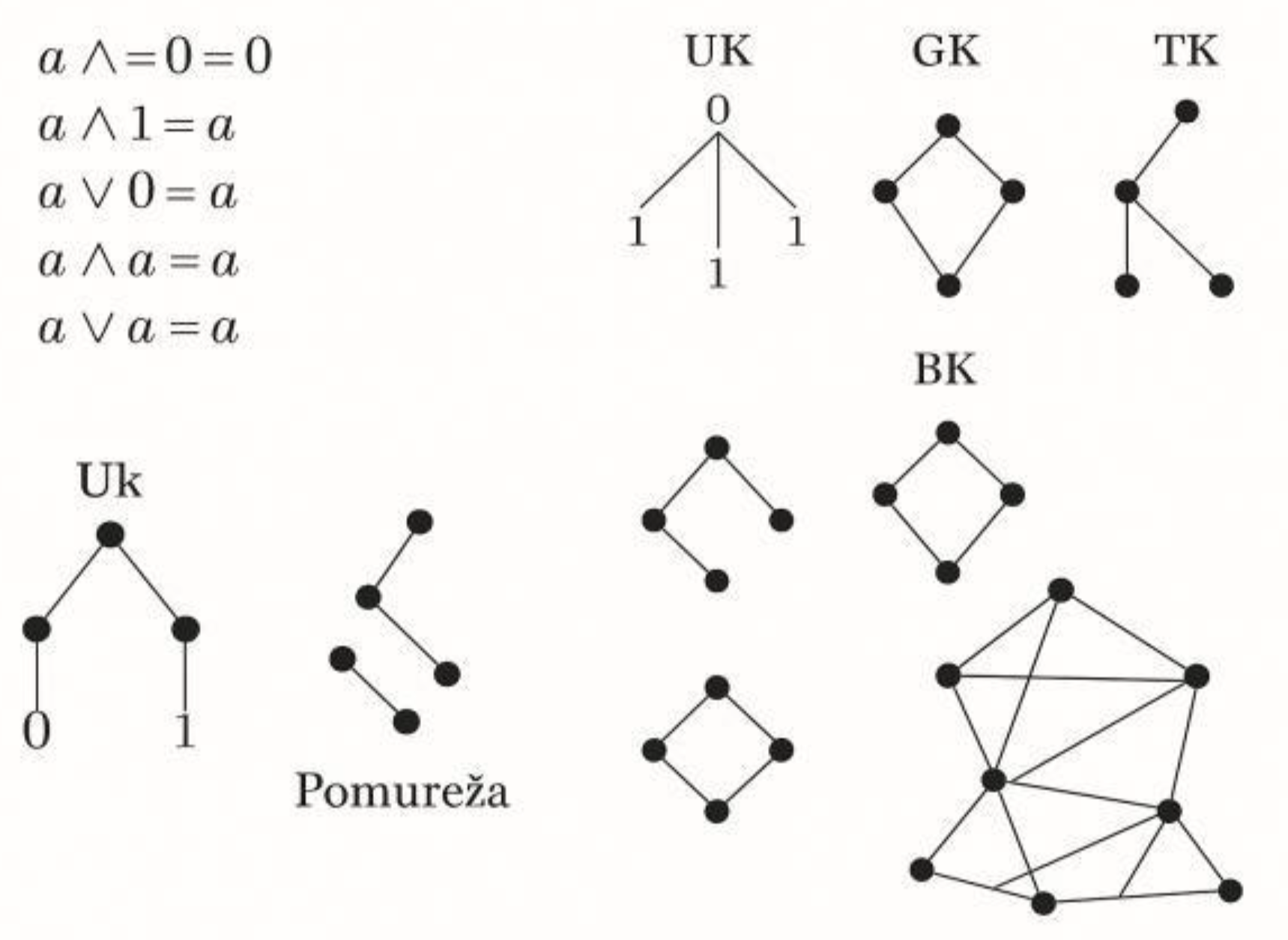
Figure 6.
Boolean Algebra Axioms and Network Types: Uk, Gk, Tk, Bk, and Subnetworks.
-
Top left – Boolean Algebra Axioms:
- o
-
Presents fundamental Boolean rules:
- ▪
- a∧0=0
- ▪
- a∧1=a
- ▪
- a∨0=a
- ▪
- a∧a=a
- ▪
- a∨a=a
These axioms are the basis for constructing and analyzing logic expressions and networks.
-
Middle and Right – Network Visualizations:
- o
- Uk (Union Network): One central node connected to several others producing output 1, representing disjunction.
- o
- Gk (Generalized Network): A complex web of nodes, possibly with loops or cycles.
- o
- Tk (Topological Network): Hierarchical with clear directionality (e.g., tree structures).
- o
- Bk (Boolean Network): Dense and interconnected, based on logical rules.
-
Bottom – Subnetworks and Network Structure:
- o
- A subnetwork is a subset of a larger network preserving the same structure and rules.
- o
- These visualizations show how logic expressions, once translated into graphs, can be decomposed into smaller functional units.
This illustration shows how the core rules of Boolean algebra shape network behavior and structure. Every logic expression can be interpreted as a graph belonging to a classification group (Uk, Gk, Tk, Bk). Subnetworks enable deeper analysis, essential for understanding complex digital and logical systems.
Conclusion, Discussion and Recommendations for Further Research
The results obtained through the developed MATLAB application demonstrate that Boolean algebra can be successfully integrated into the analysis and classification of network structures. The application enables users to input two mathematical functions which are automatically displayed on a coordinate system, providing a clear visual representation of their mutual relationships, intersection points, and behavioral patterns within the domain.
The detected intersections of the functions are of particular importance, as they represent key points in network classification. Based on this data, the application generates logical expressions which are then transformed into Boolean operations—union and intersection— interpreted as logical disjunction and conjunction, respectively. Each step is accompanied by analytical explanations, along with the automatic generation of truth tables, which allow for the derivation of minimized expressions in Disjunctive Normal Form (DNF) and Conjunctive Normal Form (KNF).
What stands out is the fact that the application not only offers visualization and symbolic computation but also enables logical inference to determine whether the given network belongs to one of the defined classes—Gk, Uk, Tk, Hk, or Bk. This functionality enhances the understanding of relations between functions and supports more precise modeling of networks in both educational and research contexts.
Overall, the application successfully bridges algebraic principles with graphical analysis and logical reasoning, making it a valuable tool for digital logic, set theory, and applied mathematical education. It serves as an example of how interactive tools can deepen theoretical knowledge and facilitate the study of complex systems.
Recommendations for Further Research:
Future research can focus on expanding the application to support:
- Multivariable functions and dynamic network generation in real-time.
- Integration with symbolic AI for automatic recognition and simplification of logical patterns.
- Classification and simulation of real-world data networks (e.g., social, biological, or communication networks).
- Exporting results in standardized formats for use in scientific publications or external systems.
- Enhancing the interface for use in STEM education at various levels of complexity.
Such developments would further enhance the relevance and applicability of this tool in both academic and professional environments.
References
- Delaplace, F., & Ivanov, S. (2020). Bisimilar conversion of multi-valued networks to Boolean networks. arXiv preprint arXiv:2001.07371. https://arxiv.org/abs/2001.07371.
- Müssel, C., Hopfensitz, M., & Kestler, H. A. (2020). Concepts in Boolean network modeling: What do they all mean? Computational and Structural Biotechnology Journal, 18, 571–582. [CrossRef]
- Rozum, J. C., Zañudo, J. G. T., Gan, X., Deritei, D., & Albert, R. (2020). Parity and time-reversal elucidate both decision-making in empirical models and attractor scaling in critical Boolean networks. arXiv preprint arXiv:2009.05526. https://arxiv.org/abs/2009.05526.
- Schwieger, R., Bender, M. R., Siebert, H., & Haase, C. (2021). Classifier construction in Boolean networks using algebraic methods. arXiv preprint arXiv:2108.08599. https://arxiv.org/abs/2108.08599.
- Sun, J., AlMomani, A. A., & Bollt, E. (2020). Data-driven learning of Boolean networks and functions by optimal causation entropy principle (BoCSE). arXiv preprint arXiv:2006.01023. https://arxiv.org/abs/2006.01023.
- Xiao, G., Bai, Z.-J., & Ching, W.-K. (2020). A modified orthogonal matching pursuit for construction of sparse probabilistic Boolean networks. arXiv preprint arXiv:2008.09767. https://arxiv.org/abs/2008.09767.
- Galić, R., Čajić, E., & Stojanovic, Z. Stochastic Methods in Artificial Intelligence, 13 November 2023. PREPRINT (Version 1) available at Research Square [https://doi. org/10.21203/rs. 3. rs-3597781/v1].
- Z. Stojanović and E. Čajić, "Application of Telegraph Equation Soluton Telecommunication Signal Trasmission and Visualization in Matlab," 2019 27th Telecommunications Forum (TELFOR), Belgrade, Serbia, 2019, pp. 1-4. [CrossRef]
Disclaimer/Publisher’s Note: The statements, opinions and data contained in all publications are solely those of the individual author(s) and contributor(s) and not of MDPI and/or the editor(s). MDPI and/or the editor(s) disclaim responsibility for any injury to people or property resulting from any ideas, methods, instructions or products referred to in the content. |
© 2025 by the authors. Licensee MDPI, Basel, Switzerland. This article is an open access article distributed under the terms and conditions of the Creative Commons Attribution (CC BY) license (http://creativecommons.org/licenses/by/4.0/).
Copyright: This open access article is published under a Creative Commons CC BY 4.0 license, which permit the free download, distribution, and reuse, provided that the author and preprint are cited in any reuse.


