
Submitted:
07 May 2025
Posted:
08 May 2025
You are already at the latest version
Abstract
Hydraulic fracturing assisted oil displacement (HFAOD) can improve the productivity of offshore low-permeability reservoirs, but challenges such as rapid productivity decline, difficulty in controlling fracture height, and unclear influence of geological and operational factors on key parameters of HFAOD persist. This study establishes a fluid-solid coupling model for HFAOD and verifies its accuracy with field data. It clarifies laws of HFAOD fracture propagation and fluid infiltration, conducts sensitivity analyses to identify dominant factors affecting fracture propagation and fluid infiltration, and achieves quantitative characterization and rapid prediction of fracture half-length and infiltration radius. The results indicate that the HFAOD fluid undergoes simultaneous infiltration during fracture propagation. In the initial stage of HFAOD, the fluid primarily contributes to fracture creation with limited infiltration, while in the middle to late stages, fracture propagation diminishes and the infiltration radius expands significantly. The dominant controlling factors affecting HFAOD fracture propagation are reservoir thickness and cumulative injection volume, the dominant controlling factors affecting HFAOD fluid infiltration are permeability and formation pressure coefficient before HFAOD, which should be given special attention on site. This study quantifies the relationships between HFAOD key parameters (fracture half-length and infiltration radius) and their dominant controlling factors and establishes a mathematical model for rapid prediction of these parameters. The research results provide a theoretical basis for optimizing HFAOD designs in offshore low permeability reservoirs.
Keywords:
Hydraulic fracturing assisted oil displacement
; Offshore low permeability
; Fracture propagation
; Infiltration radius
; Dominant controlling factors
; Parameter prediction
1. Introduction
Fracturing oil displacement technology, also known as “Hydraulic fracturing assisted oil displacement (HFAOD)”, is a construction technique summarized by Oilfields in recent years through practical experience to efficiently develop low-permeability, tight oil and gas reservoirs. It primarily addresses challenges such as scattered remaining oil distribution, "water injection failure and oil production inefficiency", high difficulty in chemical flooding, and formation energy depletion [1]. In 2017, Daqing Lamadian Oilfield [2] conducted China’s first field trial of HFAOD technology, achieving a daily liquid increase of 98 tons and a daily oil increase of 3.2 tons. Subsequently, HFAOD technology has been trialed in low-permeability and tight reservoirs such as Daqing Changyuan [3], Shanshan Oilfield [4], Tuha Oilfield [5], Shengli Oilfield [6-9], Yanchang Oilfield [10], and Jiangsu Oilfield [11], demonstrating more significant oil production effects compared to conventional fracturing. HFAOD technology utilizes hydraulic fracturing to propel large volumes of chemical agents deep into the reservoir above and below the fractures, rapidly replenishing formation energy, mobilizing scattered remaining oil into enriched zones, and achieving efficient oil displacement. HFAOD technology shifts the focus of conventional hydraulic fracturing from promoting fracture propagation to delaying fracture extension, thereby inhibiting premature breakthrough of the chemical agent front caused by rapid fracture growth. This enhances effective swept volume expansion and reduces chemical agent loss along the flow path through high-pressure injection. HFAOD operations are primarily categorized into “forward HFAOD" and "reverse HFAOD.” “Forward HFAOD” involves high-pressure injection of chemical agents from an injection well. After fracturing the formation, the agents gather scattered remaining oil along the displacement direction, continue driving it toward the production well. Post-fracturing, the fractures gradually close, and the injection well resumes conventional water injection. “Reverse HFAOD” involves high-pressure injection of chemical agents into a production well. After fracturing the formation, the agents gather scattered remaining oil near the production well under the displacement pressure differential. Post-fracturing, the fractures gradually close, production resumes following a well-soaking period, and injection wells return to conventional water injection. Field tests demonstrate that reverse HFAOD outperforms forward HFAOD [12]. Offshore oilfields face challenges such as poor reservoir properties, strong heterogeneity, poor connectivity in certain well groups, ineffective water injection, resulting in low formation energy, rapid production decline. Additionally, the thin vertical reservoir layers, poor interlayer isolation also make it difficult to control the fracture height [13]. Currently, pilot trials of HFAOD are being conducted in offshore low permeability oilfields. The project for three wells in the Weizhou 12-2 Oilfield of the South China Sea has been successfully completed, with post-operation results showing significant increases in oil production and injection efficiency. This operation utilized 13,356 m³ of fluid and 175 m³ of proppant, marking the largest-scale HFAOD operation implemented by CNOOC to date. Following HFAOD operations, Well B13 achieved a 50% increase in oil production [13], with current production continuing to rise. However, the quantitative impact of HFAOD key parameters on operational effectiveness remains unclear.
During HFAOD operations, fracture propagation significantly impacts well productivity, and the fracture growth patterns in HFAOD differ from those in conventional hydraulic fracturing. Conventional hydraulic fracturing focuses solely on fracture creation, aiming to minimize fluid infiltration of the working fluid during fracture propagation to ensure effective action on the fracture walls. HFAOD requires consideration of both fracture propagation during the fracturing process and the fluid infiltration volume and infiltration patterns. Therefore, quantitative characterization of fracture half-length and infiltration radius during HFAOD is critical for evaluating displacement effectiveness and optimizing fracturing operations. Zhang et al. [14] conducted HFAOD physical experiments to investigate factors affecting HFAOD breakdown pressure. Based on CT scanning, they analyzed fracture distribution characteristics in HFAOD at the micrometer scale, introduced pore structure parameters, and developed a quantitative characterization method for HFAOD fractures. Xu et al. [15] established a three-dimensional mathematical model for fluid-solid coupled fracture propagation under HFAOD conditions, targeting the infiltration process in Class III reservoirs of Daqing Oilfield. The model incorporates normal seepage stress and coefficient within fractures, as well as seepage pressure and coefficient in the matrix. Fracture parameters and pressure distribution were solved using the Picard iteration method. Zha et al. [16] established a constitutive equation between fluid and matrix based on Biot's linear elastic contact theory, discretized the rock stress-strain field using the virtual element method, and quantitatively characterized the dynamic fracture propagation during HFAOD water injection. Additionally, Ma et al. [17] and Shen et al. [18] characterized reservoir porosity-permeability changes after HFAOD and conducted optimization studies on HFAOD injection parameters, using specific blocks in the Bonan Oilfield and a tight sandstone reservoir as research targets. Their work clarified the impact of injection rate and cumulative injection volume on HFAOD effectiveness. In addition to HFAOD fracture propagation, researchers have also investigated factors influencing fracture growth in conventional hydraulic fracturing. Fan et al. [19] proposed the concept of dynamic fractures for low-permeability reservoirs, analyzing their evolution process from initiation, propagation, to closure, and developed a mathematical model to describe dynamic changes in fracture geometry and properties. Guo et al. [20] established a continuous fracture network model for shale gas reservoir fracturing, incorporating key factors such as fracture height, fracture asymmetry, and fluid infiltration. They proposed forward and inverse algorithms for the model and validated through case studies that its accuracy exceeds 90%. Zhao et al. [21] developed a new pseudo-3D (P3D) hydraulic fracture propagation model to address fracture height growth in thin-layer sandstone. This model couples the wedge-shaped fracture model, penetrative fracture propagation model, PKN model, and Carter infiltration model. They further analyzed the influence of factors such as injection ratio, infiltration coefficient, stress difference between reservoir and adjacent layers, and interlayer fracture toughness on fracture propagation. Regarding dominant factors controlling fracture propagation, Zhang et al. [22] investigated the effects of gravel strength, cementation strength, and horizontal stress difference on fracture extension through discrete element numerical simulation. They further quantitatively analyzed the impact of these factors on dimensionless fracture length using the random forest method. He et al. [23] integrated core sample testing, well logging, and fracturing data to analytically investigate the dominant factors controlling hydraulic fracture propagation in coalbed methane reservoirs. Regarding fracturing fluid infiltration, Luo et al. [24] summarized the strengths and weaknesses of existing fluid infiltration models, developed and solved a two-dimensional fracturing fluid infiltration model incorporating dynamic fracture propagation, and demonstrated that fracture length variation significantly impacts fluid infiltration. Wang et al. [25] established a spontaneous fracturing fluid imbibition model driven by capillary forces for shale gas reservoirs and introduced a dimensionless imbibition rate parameter to analyze key factors influencing fracturing fluid infiltration. Zhou et al. [26] developed different fluid infiltration behavior models based on HFAOD fluid viscosity and the reservoir basic physical properties and clarified the impact of fracturing fluid infiltration on fracture initiation mechanisms.
It is evident that research on fracture propagation and fracturing fluid infiltration in hydraulic fracturing and HFAOD leans more toward numerical simulations. Compared to laboratory experimental evaluation, numerical simulations offer easier control over parameters and laws, thereby facilitating the proposal of the most robust optimized fracturing design plans [27]. In summary, the influencing factors of fracture propagation in hydraulic fracturing and HFAOD can be categorized into geological factors and operational factors. While some studies have reported on factors affecting HFAOD fracture propagation, HFAOD processes differ from conventional fracturing by requiring consideration of the coupling between fracture extension and HFAOD agent infiltration. However, existing research remains focused on conventional fracturing, and the dominant controlling factors of HFAOD agent infiltration have not yet been reported. Additionally, after clarifying the dominant controlling factors of fracture half-length and HFAOD agent infiltration, accurately predicting fracture half-length and infiltration radius under multi-factor control is critical for developing optimized charts of HFAOD fracture half-length and infiltration radius, thereby providing critical guidance for HFAOD operations.
This study establishes a finite element numerical model based on the rock stress equilibrium equations, pore fluid flow equations, and fracture initiation criteria during HFAOD processes, incorporating the coupling effects of fracture propagation and fluid infiltration. Utilizing the finite element platform, we investigate the impacts of geological and operational factors on HFAOD fracture extension and agent infiltration. By applying the entropy weight-based grey relational analysis method, this study identifies the dominant controlling factors of HFAOD parameters (fracture half-length and infiltration radius), constructs a quantitative characterization model for HFAOD parameters, and develops optimized charts for fracture half-length and infiltration radius. These charts enable the prediction of HFAOD fracture half-length and agent infiltration radius under the influence of dominant factors, providing a basis for HFAOD effectiveness evaluation and operational parameter optimization.
2. Theory and Method
2.1. Physical Model and Assumptions
The physical process of HFAOD involves injecting HFAOD agents into the formation at high pressure and high rate to create fractures. Through the simultaneous fracturing and infiltration process (“fracture propagation→HFAOD agent infiltration”), as shown in Figure 1(a), the agents penetrate deeper and farther into the reservoir, effectively expanding the swept volume. Since HFAOD agents are surfactants, they reduce oil-water interfacial tension, alter wettability, decrease residual oil saturation, and enhance oil displacement. Thus, the oil recovery is further enhanced through both swept volume expansion and oil displacement efficiency enhancement.
During HFAOD agent injection, the fluid flows from the wellbore to artificial fractures and then from the fractures to the matrix. The simultaneous fracturing and infiltration process can be equivalently characterized as two independent processes—fracture creation and infiltration—using a pre-existing fracture method, as shown in Figure 1(b). By artificially pre-embedded fractures with specific geometry and conductivity, HFAOD agents are injected into the reservoir containing fractures and matrix through production wells to simulate infiltration, during which fractures do not propagate further. The flow of HFAOD fluid is divided into tangential flow and normal flow: tangential flow induces pressure buildup at the fracture tip, leading to fracture opening, while normal flow represents fluid infiltrates from the fractures during HFAOD operations.
Assumptions include:(1) The formation is a homogeneous, isotropic porous medium in a linear elastic state. (2) Temperature effects on fractures are neglected. (3) The HFAOD fluid is incompressible, rock pores are fully saturated, and physicochemical interactions between the HFAOD fluid and surrounding rock are ignored during operations. (4) Fluid inertial effects are neglected.
2.2. Mathematical Model
During fracture propagation, rock deformation and fluid flow within fractures necessitate consideration of fluid-solid coupling in HFAOD processes. Prior to fracture initiation, the rock is influenced by in-situ stresses and pore pressure. When the fluid pressure within the fracture reaches the rock’s tensile strength, fractures initiate and propagate along the failure direction. Both pre-initiation and post-failure stages are static processes, while fracture propagation is dynamic. The mathematical model primarily includes: rock stress equilibrium equations, pore fluid flow equations and fracture initiation and propagation criteria.
2.2.1. Rock Stress Equilibrium Equations
Based on the principle of virtual work in statics, the system remains in equilibrium before fracture propagation, where the total virtual work from constraint forces and fluid pressure equals zero. The stress equilibrium equation is shown in follows:
where, δε is the virtual displacement of the rock, m; f is the body force acting on the rock element, N/m³; δu is the virtual strain of the rock, m; dV in the volume element of the rock unit, m³; T is the surface force acting on the rock contact face, N/m²; dS is the area element of the rock contact face, m².
2.2.2. Pore Fluid Flow Equations
Within the pore space of a unit reservoir rock, the mass of HFAOD fluid entering the pores equals the mass exiting during a given time period, as described by the continuity equation below:
where, vw is the HFAOD fluid flow velocity, m/s; nw is the ratio of HFAOD fluid volume in unit pores to unit rock volume, dimensionless; J is the change rate of pore volume, dimensionless; ρw is the density of HFAOD fluid, kg/m3; δv is the virtual velocity of rock motion, m/s.
During fracture propagation, the permeability and pore pressure of the reservoir rock undergo changes, described by the following equations:
where, φ is the porosity, dimensionless; φ0 is the initial porosity, dimensionless; is the volumetric strain rate of the rock, dimensionless; K is the permeability, μm2; K0 is the initial permeability, μm2.
The HFAOD fluid is a surfactant-based agent, distinct from conventional fracturing fluids (e.g., guar gum), and behaves as a newtonian fluid. The expressions for tangential flow and normal flow of the HFAOD fluid are as follows:
Tangential flow equation:
where, q is the volumetric flow rate of HFAOD fluid, m³/s; w is the fracture width, m; μ is the viscosity coefficient of the fluid; pf is the fluid pressure within the fracture, MPa.
The normal flow equation for fluid at the upper and lower surfaces of the fracture element is derived by introducing volumetric flow rate to model HFAOD fluid infiltration:
where, pt, pb is the pore pressures at the upper and lower surfaces of the fracture, MPa; qt, qb is the fluid infiltration volumes at the upper and lower surfaces, m³/s; ct, cb is the fluid infiltration coefficients at the upper and lower surfaces.
2.2.3. Fracture Initiation and Propagation Criteria
Based on the assumptions and practical conditions, since HFAOD fractures primarily initiate via tensile failure mode, the maximum principal stress criterion is selected as the fracture initiation criterion for reservoir rock, expressed as follows:
where, t0n represents the critical tensile stress in the normal direction, corresponding to the tensile strength of the rock; t0s, t0t denote the critical tensile stresses in the two tangential directions; < > indicates that stress takes positive value—compressive stresses or compressive deformation in the element do not induce damage.
When the tensile stress in any direction of the element reaches the tensile strength, fractures form within the element to create fracture surfaces. In practical fracture initiation processes, based on rock fracture mechanics, the energy release rate is introduced to address limitations in the maximum stress criterion for determining rock fracture initiation. This section adopts the BK criterion as a supplementary method. When the first and second tangential fracture energies of the element are equal, the basic form of the criterion is expressed as follows:
where, Gn, Gs, Gt is the work done by the normal, first tangential, and second tangential stresses on the element displacement, N/mm, Gs=Gt; GnC, GsC, GtC is the fracture energy in the normal, first tangential, and second tangential directions of the element, N/mm; GC is the total fracture energy, N/mm; η is the constant characterizing rock properties.
2.3. Grid Generation
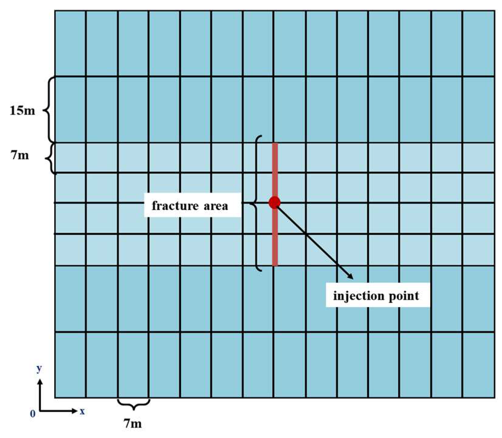
The model employs homogeneous grids parallel to the fracture direction in the X-axis and heterogeneous grids perpendicular to the fracture direction to finely characterize fracture propagation and infiltration processes. The numerical model dimensions are: X-direction (width): 300 m (minimum horizontal principal stress direction), Y-direction (height): 90 m (vertical principal stress direction), Z-direction (length): 300 m (maximum horizontal principal stress direction). The formation is divided into a reservoir layer (28 m) and upper/lower barrier layers (30 m). The injection point is located at the center of the reservoir. Figure 4 illustrates the numerical simulation grid discretization process.
Figure 2.
Schematic diagram of grid generation in numerical simulation.
3. Application
3.1. Validation
Offshore oilfields predominantly feature complex fault-block reservoirs with low permeability, thick oil layers, and insufficient formation energy replenishment. In some blocks, incomplete well patterns and poor fluid injection efficiency hinder production. Well A, an HFAOD-implemented well in an isolated fault block, has an effective thickness of 29.7 m, porosity of 17.6%, and permeability of 20.8mD, indicating development potential. However, prolonged depletion-driven production has reduced its formation pressure coefficient to 0.78, with a recovery factor below 10%. Using Well A as a validation model, this study analyzes HFAOD fracture propagation and fluid infiltration. Key rock mechanical and operational parameters for Well A are listed in Table 1.
Under the condition of constant injection rate and cumulative injection volume, the fractures propagation was simulated. By adjusting relevant parameters in Table 1, the variation in wellhead pressure was obtained and compared with field-measured values (Figure 2). The simulation accuracy for wellhead pressure reached 86.3%. The simulated fracture half-length for Well A was 199 m, while the post-fracturing inversion result was 203 m, yielding a simulation accuracy of 92.6%.
Figure 3.
Construction dynamic verification of Well A.
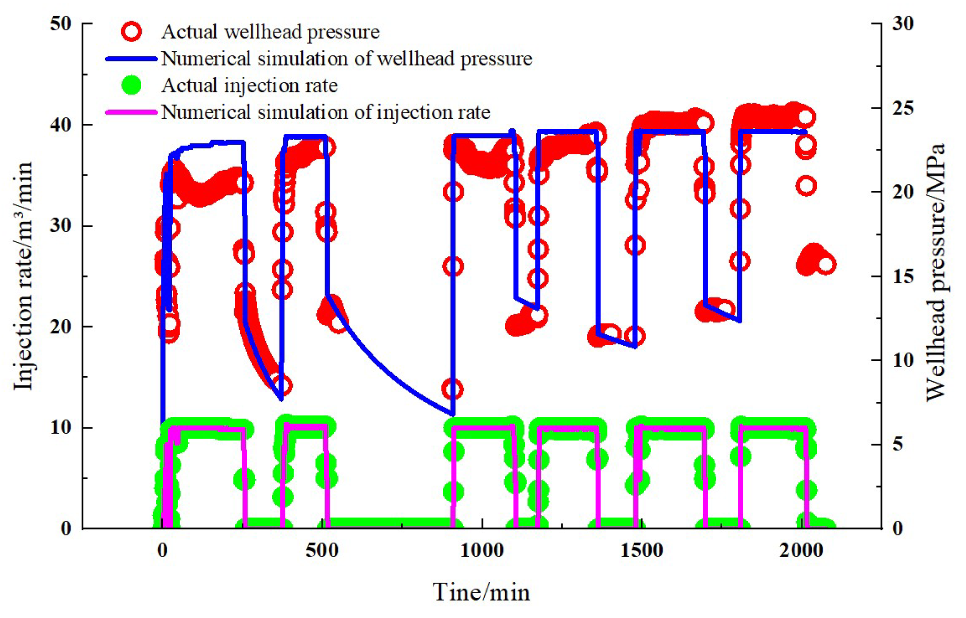
Figure 4.
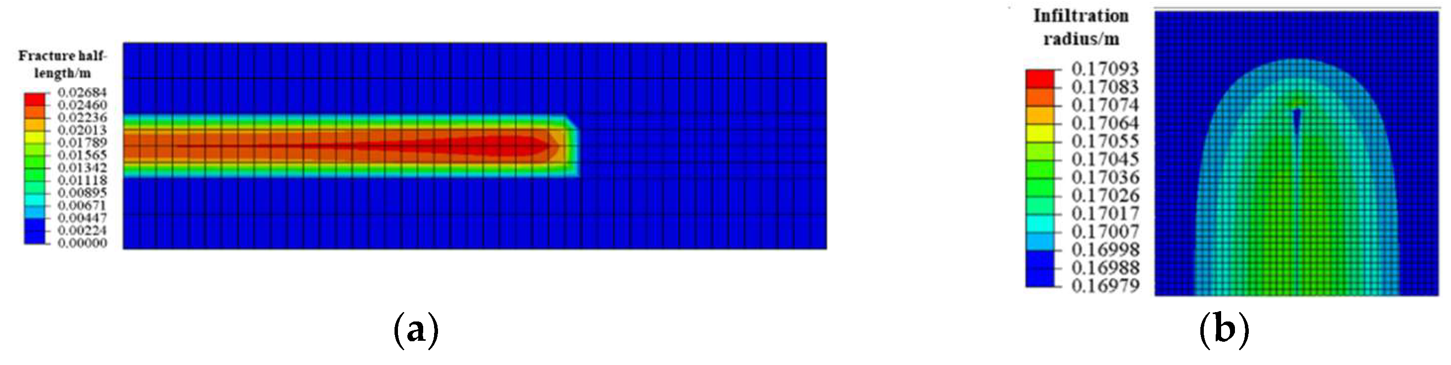
Simulation results of fracture half-length and infiltration radius for Well A. (a) Fracture half – length; (b) Infiltration radius.
Figure 4.
Simulation results of fracture half-length and infiltration radius for Well A. (a) Fracture half – length; (b) Infiltration radius.
3.2. HFAOD Fracture Propagation and HFAOD Fluid Infiltration Law
The essence of HFAOD lies in achieving the dual objectives of "fracture creation & permeability enhancement + energy replenishment & oil displacement" through the synergistic interaction of fracture propagation and HFAOD fluid infiltration. This is accomplished by high-rate and high-pressure injection of large volumes of low-viscosity HFAOD fluid into deep reservoir zones along the fracture path. Due to the low viscosity of HFAOD fluid, rapid infiltration occurs, swiftly replenishing formation energy to mobilize dispersed residual oil and achieve efficient oil displacement. Fracture propagation initiates as the HFAOD fluid injection pressure surpasses the formation breakdown pressure, subsequently extending along the maximum principal stress direction and modifying reservoir porosity-permeability conditions. Simultaneously, the HFAOD fluid exhibits concurrent infiltration during fracture extension, manifesting a "fracturing-with-infiltration" dynamic. Figure 5a, b, and c illustrate the dynamic propagation of fractures during different stages of HFAOD fluid injection. As the HFAOD injection time increases, the fracture exhibits continuous extension, and the fracture half-length increases accordingly. Figure 5d, e, and f depict the dynamic expansion of infiltration during HFAOD injection. As the fracture half-length continuously extends, the infiltration radius progressively increases, demonstrating that fracture propagation and fluid infiltration occur simultaneously throughout the HFAOD process. HFAOD fracture propagation is divided into two distinct stages: rapid propagation and discontinuous propagation. The initial stage of fracturing fluid primarily serves to create fractures, with the fluid accumulating at the perforation points to rapidly initiate and propagate fractures. At 5000s of injection time, the fracture half-length reaches 61 m, marking the entry into the mid-stage of fracturing. During the mid-stage, the fracture half-length extends to 153 m, representing a 150.8% increase in length. In the later stage, the fracture length reaches 187 m, showing a 22.22% growth. This indicates that as the fracturing process progresses into the mid-late stages, the fracture propagation rate gradually decelerates. During this phase, the fracturing fluid primarily undergoes filtration, while the dynamic fracture half-length advances at a progressively slower speed. Concurrently, the flow-through area on both sides of the fracture expands, and the pressure at the fracture tip increases slowly (pressure accumulation), demonstrating energy storage characteristics. The infiltration of HFAOD fluid also occurs in two distinct stages. In the initial stage, limited infiltration is observed as the fluid primarily focuses on fracture generation, resulting in an infiltration radius of 18m. During the mid-stage, the infiltration radius expands to 39m, representing an increase of 116.2%. In the late stage, the infiltration radius further grows to 102m, with a growth rate of 162.5%. This demonstrates that during mid-to-late stage, as fracture propagation gradually slows, infiltration becomes dominant, leading to accelerated growth of the infiltration radius.
4. Results and Discussion
4.1. Sensitivity Analysis
A fluid-solid coupling mathematical model for HFAOD was adopted. Based on the basic parameters of Well A, 26 schemes were designed as shown in Table 2. Geological factors (reservoir thickness, permeability, and formation pressure coefficient before HFAOD) and operational factors (HFAOD fluid injection rate, HFAOD fluid viscosity, and cumulative injection volume) were considered to analyse their impacts on HFAOD fracture propagation and fluid infiltration. A sensitivity analysis was conducted.
4.1.1. Geological Factors
(1) Thickness
Considering reservoir thicknesses of 4 m, 13 m, 20 m, 28 m, 40 m, and 50 m, Figure 6 shows the time-dependent variation of fracture half-length and infiltration radius under different thicknesses. The greater the reservoir thickness, the shorter the HFAOD fracture half-length. Greater reservoir thickness imposes more constraints on fracture initiation and propagation. Thicker reservoirs require overcoming higher rock resistance during the HFAOD process, necessitating greater HFAOD fluid pressure and more energy to form and extend fractures. Under the conditions of identical injection rate and cumulative injection volume, increased reservoir thickness reduces fluid intake per unit thickness, leading to decreased fluid energy density per unit volume. This weakens fracture propagation capacity and results in shorter fracture half-length. To create long fractures (fracture half-length > 100 m) under the given model parameters, the reservoir thickness should be less than 40 m. The thinner reservoirs result in larger contact area between HFAOD-formed fractures and the reservoir. Under the same cumulative injection volume, the dynamic fracture half-length is longer, the fill degree of HFAOD fluid in the reservoir is higher, and the fracture proportion range of HFAOD within the reservoir increases. This enhances the flow area, leading to a larger infiltration radius.
(2) Permeability
Considering reservoir permeabilities of 10mD, 20mD, 50mD, 150mD, and 400mD, Figure 7 shows the time-dependent variation of fracture half-length and infiltration radius under different permeabilities. Reservoirs with lower permeability exhibit longer HFAOD fracture half-lengths because fracture propagation requires sufficient net pressure. Insufficient net pressure reduces fracture propagation capacity, hindering effective accumulation of fracture tip pressure and thereby limiting fracture length growth. In low-permeability reservoirs, the high fluid flow resistance and slow HFAOD fluid infiltration rate allow the fracture tip to maintain elevated net pressure, providing sustained driving force for fracture propagation and greater growth potential for fracture half-length. According to the material balance theory, fracture propagation requires sufficient HFAOD fluid volume to maintain fracture internal pressure. The larger the fracture half-length, the more injected HFAOD fluid is consumed in driving fracture extension rather than HFAOD fluid infiltration, thereby suppressing the growth of infiltration radius. When the permeability exceeds 100mD, fracturing fluid tends to experience higher leak-off, making it difficult to create long fractures. As permeability increases, the flow resistance of the fluid decreases, this leads to a greater volume of fracturing fluid infiltrating the formation, resulting in lower utilization efficiency of the fluid for fracture propagation. Under the same injection volume, the fracture half-length decreases, while the infiltration radius of the HFAOD fluid increases.
(3) Formation Pressure Coefficient before HFAOD
Considering the formation pressure coefficient before HFAOD of 0.5, 0.7, 1, and 1.3, Figure 8 shows the fracture half-length and infiltration radius vs. time curves under different formation pressure coefficient before HFAOD. When the formation pressure coefficient before HFAOD exceeds 1, under identical cumulative injection volume, the effective pressure differential between fluid pressure within the fracture and formation pressure becomes greater. This provides enhanced driving force for fracture propagation, resulting in a more pronounced increase in fracture half-length within a given period. When the formation pressure coefficient before HFAOD is less than 1, after fracture initiation during the HFAOD process, the energy required for fracture propagation relies more predominantly on the pressure of injected HFAOD fluid owing to insufficient formation pressure support. Once the injection pressure becomes insufficient to overcome rock resistance, fracture propagation becomes restricted, thereby preventing significant growth of the fracture half-length. Since the pressure of the injected fracturing fluid exceeds the formation pressure at this stage, the resulting pressure differential provides a driving force for fluid infiltration. A larger pressure differential accelerates the infiltration rate of the HFAOD fluid, enabling it to infiltrate a broader area within a shorter time, thereby achieving a larger infiltration radius. As evidenced by Figure 8, higher formation pressure coefficients before HFAOD facilitate the creation of longer fractures with reduced HFAOD fluid infiltration. Under the current model parameters, when the formation pressure coefficient before HFAOD ranges from 0.7 to 1.0, an optimal balance between fracture half-length and infiltration radius can be achieved.
4.1.2. Construction Factors
(1) Injection Rate
Considering injection rates of 2 m³/min, 5 m³/min, 6 m³/min, and 8 m³/min, Figure 9 presents the fracture half-length and infiltration radius vs. time curves under different injection rates. During the initial stage of HFAOD, the injection rate largely determines the increase rate of pressure. A higher injection rate results in faster pressure buildup. A larger injection rate means more HFAOD fluid is injected into the formation per unit time, enabling faster pressure accumulation at the fracture tip. Based on the principles of elastic mechanics and fracture mechanics, fracture initiation and propagation require sufficient pressure to overcome the rock's tensile strength. When the injection rate is elevated, the fracture tip attains the fracture initiation pressure more rapidly, thereby promoting the growth of fracture half-length. During the later stage of HFAOD, as fractures propagate and HFAOD fluid continues to be injected, fracture extension reaches an equilibrium state where the relationship between injection rate and fracture half-length becomes less pronounced compared to the initial stage. When the injection rate exceeds 5 m³/min, the fracture half-length exhibits significant growth acceleration. Therefore, achieving long fractures requires maintaining injection rates above 5 m³/min. Under identical cumulative injection volumes, elevated injection rates increase HFAOD fluid volume delivered per unit time, resulting in sustained pressure escalation within fractures. This heightened fluid volume promotes rapid fracture extension and fills pores/fractures in the near-wellbore zone, prompting rapid fracture propagation into distal regions while reducing HFAOD fluid infiltration. Conversely, lower injection rates prolong injection duration, allowing extended HFAOD fluid infiltration within the matrix, thereby ultimately increasing the infiltration radius.
(2) Viscosity
Considering HFAOD fluid viscosities of 1 mPa·s, 3 mPa·s, 5 mPa·s, and 10 mPa·s, Figure 10 illustrates the temporal evolutions of fracture half-length and infiltration radius under varying HFAOD fluid viscosities. Fracture propagation is primarily driven by the injection fluid pressure and the fluid's viscous forces. Therefore, under the conditions of stable HFAOD fluid injection pressures, the use of high-viscosity HFAOD fluids reduces the filtration coefficient due to restricted fluid mobility, resulting in diminished fluid loss. This significantly elevates net pressure within fractures, thereby enhancing fracture propagation. Conversely, low-viscosity HFAOD fluids exhibit relatively uniform pressure distribution, allowing fluid infiltration into the adjacent reservoir matrix. Consequently, sustained pressure accumulation within fractures becomes challenging, leading to decelerated fracture extension due to insufficient pressure support. This ultimately restricts fracture half-length development. Under identical cumulative injection volumes and injection rates, low-viscosity HFAOD fluids exhibit accelerated infiltration velocities, facilitating rapid distal diffusion and expansive infiltration zone development. This enhanced penetration capability allows deeper fluid invasion into the formation, thereby increasing the infiltration radius. When the permeability is 20mD, selecting a viscosity range of 1-5mPa·s can achieve a larger infiltration radius while maintaining a significant fracture half-length, thereby realizing the comprehensive optimal HFAOD effect.
(3) Cumulative Injection Volume
Considering cumulative injection volumes of 4800 m³, 13440 m³, 14400 m³, and 16000 m³, Figure 11 displays the temporal evolutions of fracture half-length and infiltration radius under varying cumulative injection volumes. During HFAOD fluid injection, the continuous increase in cumulative injection volume during the initial phase elevates internal fracture pressure as more fluid enters the fracture system. When the net pressure exceeds the rock's tensile strength, the fracture half-length undergoes sustained propagation with significant growth increments. When the cumulative injection volume reaches 2000 m³, the fracture half-length growth rate demonstrates marked deceleration. This phenomenon is attributed to two primary mechanisms: The relatively lower viscosity of HFAOD fluid compared to conventional fracturing fluids enhances matrix infiltration during injection, reducing the effective fluid volume available for fracture propagation. Even with ostensibly sufficient cumulative injection volumes, inadequate energy delivery for fracture extension results in diminished fracture half-length growth. Beyond critical injection volumes, equilibrium establishes between fluid injection pressure and formation constraints (including in-situ stress and rock tensile strength), causing fracture half-length stabilization despite continued volume increases. Concurrently, the infiltration radius exhibits progressive expansion with cumulative injection volume. During initial injection stages (low-volume phase), HFAOD fluid predominantly infiltrates the near-wellbore region, resulting in limited infiltration radii. This occurs as injected fluid preferentially saturates proximal fractures and pore networks. With sustained injection, pressure transmission drives distal fluid migration, systematically enlarging the infiltration radius.
4.2. Dominant Controlling Factors
Based on sensitivity analysis results of HFAOD-induced fracture propagation and infiltration radius, a grey relational analysis method integrated with entropy weighting was implemented for dominant factor identification. The methodology's core principles involve: Entropy-weighted objective quantification: The entropy weight method objectively determines influencing weights of parameters on fracture half-length and infiltration radius by evaluating data variability magnitude, effectively circumventing subjective human bias in weight assignment. Grey relational degree calculation: Grey relational analysis quantifies inter-factor correlation intensities through relational degree computation. Hierarchical factor ranking: Final influence hierarchy is established by weighting relational degrees with entropy-derived coefficients, systematically determining the controlling sequence of geological/engineering parameters on fracture geometry and infiltration patterns. The entropy-weighted grey relational method achieves comprehensive data information utilization by integrating the objective weighting advantages of entropy-based quantification with grey theory's capability to effectively address incomplete and uncertain influencing factor information. This dual-mechanism approach enables multi-perspective comprehensive evaluation of controlling factors, thereby accurately identifying dominant parameters through systematic information synthesis.
Implementation procedure: Step1: Define fracture half-length and infiltration radius as reference sequences, define reservoir thickness, permeability, formation pressure coefficient before HFAOD, injection rate, HFAOD fluid viscosity and cumulative injection volume as comparative sequences, apply extremum normalization for dimensionless processing (Equations 9-10). Step2: Entropy weight calculation: Compute entropy values and weights for each parameter using entropy weight method (Equations 11-13). Step3: Grey relational coefficient calculation: Determine grey relational coefficients between comparative and reference sequences (Equations 14-15). Step4: Calculate the weighted relational degree between each comparative sequence and the reference sequence by combining the parameter weights obtained in Step 2 with the relational coefficients from Step 3, as formulated in Equation (16). Derive the influence weights of comparative sequences on the reference sequence from their relational degrees, as mathematically defined in Equation (17).
where, xij is the original data, representing the j-th indicator of the i-th sample; x’ij is the dimensionless data; max(xij), min(xij) are the maximum and minimum values of the dataset, respectively; I1, I2 are the sets of benefit-type (larger-the-better) and cost-type (smaller-the-better) indicators, respectively.
where, pij is the proportion of the j-th indicator under the i-th sample, dimensionless; m=26 is the number of samples.
where, Ej is the entropy value for the j-th indicator, dimensionless.
where, ωj is the entropy weight of the j-th indicator, dimensionless.
where, Δi(j) is the absolute difference between reference sequence and each comparison sequence; x0(j) is the j-th value of the reference sequence.; xi(j) is the compare the j-th value of the sequence.
where, ξi(j) is the correlation coefficient, dimensionless; ∆i(j) is the absolute difference, dimensionless; ρ is the resolution coefficient, dimensionless; ρ=0.5; ∆(min), ∆(max) representing the maximum and minimum values of the absolute difference respectively.
where, τi is the weighted correlation degree value of the i-th comparison sequence.
where, γi is the influence weight of the i-th comparison sequence.
As shown in Table 3, the influencing factors on the HFAOD fracture half-length are ranked as thickness > injection rate > formation pressure coefficient before HFAOD> HFAOD fluid viscosity > permeability > cumulative injection volume; while the influencing factors on the infiltration radius are ordered as permeability > formation pressure coefficient before HFAOD > injection rate > cumulative injection volume > HFAOD fluid viscosity > thickness. According to the weight results of factors, select factors with a weight greater than 0.2 as the main control factors. Therefore, in the process of HFAOD, attention should be focused on injection rate, thickness, formation pressure coefficient before HFAOD and permeability.
4.3. Prediction of Fracture Half-length and Infiltration Radius of HFAOD
Based on the key controlling factors identified in Section 3.2, multivariate linear regression was employed to quantify the relationships between fracture half-length, infiltration radius, and these controlling factors. Comprehensive coefficients for fracture half-length and infiltration radius were defined separately. By integrating the dimensionless numerical values of fracture half-length, infiltration radius, and their influencing factors (as derived in Section 3.2) with the key controlling factors, the comprehensive coefficients for fracture half-length and infiltration radius were established. Linear regression was then performed between these comprehensive coefficients and the dimensionless fracture half-length/infiltration radius, resulting in predictive charts and a quantitative mathematical model for fracture half-length and infiltration radius based on the key controlling factors.
Specific steps are as follows: Step 1: Define and calculate the comprehensive coefficients for fracture half-length (FI1) and infiltration radius (FI2) using the dimensionless data and weightings of the key controlling factors, as outlined in Equation (18). Step 2: Perform linear regression between the comprehensive coefficients (FI1, FI2) and the dimensionless fracture half-length/infiltration radius values, yielding fitted curves (equations) and predictive charts (Figure 12 and Figure 13). Step 3: Establish quantitative mathematical models for FI1 and FI2 by integrating the weightings of key controlling factors and dimensionless definitions from Table 3, as shown in Equations (19)-(20). Step 4: Incorporate FI1 and FI2 as independent variables into the regression formulas from Figure 12 and Figure 13, as expressed in Equations (21)-(22). Step 5: Substitute equations (19)-(20) into Equations (21)-(22) to derive the final quantitative mathematical models for fracture half-length and infiltration radius based on the key controlling factors, as demonstrated in Equations (23)-(24).
where, FI1 is the comprehensive coefficient of fracture half-length; FI2 is the comprehensive coefficient of infiltration radius; S1, S2, S3, S4 are the dimensionless cumulative injection volume, dimensionless thickness, dimensionless formation pressure coefficient before HFAOD, dimensionless permeability, respectively; W1, W2, W3, W4 are the weightings of cumulative injection volume, thickness, formation pressure coefficient before HFAOD and permeability, respectively.
Figure 12 present predictive charts for fracture half-length and infiltration radius. The red scatter points represent baseline data points, the blue dash-dotted line denotes the linear fit of these baseline data points, the light pink region indicates the 95% prediction band, and the dark pink region signifies the 95% confidence band. The 95% confidence band is calculated from known fracture half-length and infiltration radius sample data, providing a reliable range for statistical inference of fracturing-induced fracture half-length and infiltration radius. The 95% prediction band defines the interval range that, under the given prediction model, has a 95% probability of encompassing the true observed values during predictions of fracture half-length and infiltration radius, ensuring quantifiable accuracy.
where, Q, Qmax, Qmin are the injection rate, maximum injection rate, minimum injection rate, respectively, m³/min; h, hmax, hmin are the thickness, maximum thickness, minimum thickness, respectively, m; αp is the formation pressure coefficient before HFAOD; K is the permeability, mD.
where, L, Lmax, Lmin are the fracture half-length, maximum fracture half-length, minimum fracture half-length, respectively, m; R, Rmax, Rmin are the infiltration radius, maximum infiltration radius, minimum infiltration radius, respectively, m.
Equations (23)-(24) enable direct computation of HFAOD fracture half-length and infiltration radius based on their key controlling factors, achieving rapid prediction of both parameters. This methodology provides theoretical foundation for optimizing HFAOD operations to maximize treatment effectiveness.
5. Conclusions
(1) Based on the HFAOD fluid-solid coupling mathematical model established in this paper, the fracture propagation pattern in offshore low-permeability oilfields was simulated, which shows good consistency with field data. The simulation accuracy of wellhead pressure for Well A reaches 86.3%, and the simulation accuracy of fracture half-length achieves 92.6%.
(2) The fractures propagation of HFAOD and the infiltration pattern of HFAOD fluid exhibit nearly opposite trends. During the early stage of HFAOD, the HFAOD fluid primarily contributes to fracture creation, with rapid growth in fracture half-length and slower expansion of infiltration radius. In the mid-to-late stages, due to difficulty in energy accumulation at the fracture tip, the fracture propagation rate decreases, while the infiltration radius accelerates.
(3) Using the entropy-weighted grey correlation method, the analysis indicates that the dominant controlling factors affecting HFAOD fracture half-length are reservoir thickness and injection rate, while the main controlling factors influencing the HFAOD infiltration radius are reservoir permeability and formation pressure coefficient before HFAOD. Additionally, higher HFAOD fluid viscosity and larger cumulative injection volume promote the growth of fracture length but retard the increase of infiltration radius.
(4) Using multivariate linear regression, the relationships between fracture half-length/infiltration radius and their dominant controlling factors were quantified, enabling rapid prediction of HFAOD fracture half-length and infiltration radius.
Author Contributions
Investigation, writing—original draft, H.Y.; Formal analysis, J.P.; Data curation, L.W.; Investigation, Q.L.; Methodology, X.W.; Resources, conceptualization, and supervision, Y.L. Visualization, resources, and supervision, R.S. Project administration, supervision, and writing—review and editing, S.L. All authors have read and agreed to the published version of the manuscript.
Funding
This work was supported by the Major Special Project for Energy Development of CNOOC (HFKJ-ZX-GJ-2023-02).
Data Availability Statement
The data are available on reasonable request.
Conflicts of Interest
Authors Hui Yuan, Jianfeng Peng, and Lixin Wang were employed by the Zhanjiang Branch of CNOOC(China)Limited, Zhanjiang, China. Qi Li was employed by the CNOOC Energy Tech-Drilling & Production Co, Tianjin, China. remaining authors declare that the research was conducted in the absence of any commercial or financial relationships that could be construed as potential conflicts of interest.
References
- Li, Y. C.; Wang, Y. M.; Yang, G. On the Application of hydraulic fracturing assisted oil displacement technology in Daqing Oilfield. China Petroleum and Chemical Standards and Quality 2017, 37, 163–164. [Google Scholar]
- Mud Logging Engineering. "Hydraulic Fracturing Assisted Oil Displacement Pilot Test Post-Polymer Flooding in Daqing Lamadian Oilfield Achieves Initial Success." Newsletter. Mud Logging Engineering 2017, 28, 39. [Google Scholar]
- Ma, Y. J. Application of fracturing-flooding EOR technique in Type III oil reservoirs in Daqing Placanticline Oilfield. Petroleum Geology & Oilfield Development in Daqing 2021, 40, 103–109. [Google Scholar]
- Wu, Z. B.; Zeng, Q.; Li, J.; Wang, L. New effective energy-supplement development method of waterflood huff and puff for the oil reservoir with stimulated reservoir volume fracturing. Petroleum Geology and Recovery Efficiency 2017, 24, 78–83. [Google Scholar]
- Xu, J. D.; Wu, Y. S.; Xiong, Q.; Pu, X. H.; Feng, J. S.; Yue, S. J. Status and development trend of fracturing-flooding technology in low permeability reservoirs. Fault-Block Oil & Gas Field 2023, 31, 1–16. [Google Scholar]
- Ma, F. Z.; Shao, Z. R.; Li, G.; Tang, L.; Yang, P.; Yan, B. F.; Chen, D.C.; Zhuang, D.; Zhang, H. Application of dilatant pressure flooding technology in low permeability reservoir in Bonan Oilfield. Unconventional Oil & Gas 2023, 10, 58–66. [Google Scholar]
- Yang, Y.; Zhang, S. M.; Cao, X. P.; Lu, Q.; Wang, J.; Liu, H. C.; Yu, C. L.; Sun, H. X. Practice and understanding of pressure drive development technology for low-permeability reservoirs in Shengli Oilfield. Petroleum Geology and Recovery Efficiency 2023, 30, 61–71. [Google Scholar]
- Yang, Y.; Wang, J.; Bu, Y. H.; Sun, D. Practice and understanding of pressure-driven development technology in Shengli Oilfield. Petroleum Geology and Recovery Efficiency 2023, 30, 1–7. [Google Scholar]
- He, J. Q.; Liu, Z. G.; Shen, T. Z.; Chen, G.; Wang, W. L. Research and Practice on Efficient Development Technology for Tight Oil Reservoirs in Wuqi Oilfield. China Petroleum and Chemical Standards and Quality 2023, 43, 155–157. [Google Scholar]
- Huang, Y.; Jin, Z. R.; Qiao, C. G.; Zhang, H. L.; Ma, W. Practice of pressure drive water injection technology in small fault block reservoir of low permeability in Jiangsu oilfield. Petrochemical Industry Application 2022, 41, 48–51. [Google Scholar]
- Cheng, Q. C. Mechanism and technological boundaries of fracturing displacement production enhancement in extra-low and ultra-low permeability sandstone reservoirs. Northeast Petroleum University, Daqing, 2023.
- Liu, Y. K.; Wang, F. J.; Wang, Y. M.; Li, H. B.; Zhang, D.; Yang, G.; Zhi, J. Q.; Sun, S.; Wang, X.; Deng, Q. J.; Xu, H. The mechanism of hydraulic fracturing assisted oil displacement to enhance oil recovery in low and medium permeability reservoirs. Petroleum Exploration and Development 2022, 49, 752–759. [Google Scholar] [CrossRef]
- Wu, G.; Chen, X. Study on stimulation technology of low permeability oilfield. Oil and Gas Production 2023, 49, 26–28. [Google Scholar]
- Zhang, Y. F.; Yang, Y.; Sun, Z. G.; Yu, C. L.; Sun, Q.; Bei, J. P. Physical simulation of fracturing-flooding and quantitative characterization of fractures in low-permeability oil reservoirs. Petroleum Geology and Recovery Efficiency 2022, 29, 143–149. [Google Scholar]
- Xu, B.; Liu, Y.; Wang, Y. A New Method and Application of Full 3D Numerical Simulation for Hydraulic Fracturing Horizontal Fracture. Energies 2018, 12. [Google Scholar] [CrossRef]
- Ca, L. M.; Feng, Q. H.; Wang, S.; Xu, S. Q.; Liu, G. W.; Huang, W. H. Numerical simulation of fracture-flooding with virtual element method in a continuous damage model. Chinese Journal of Computational Physics 2023, 40, 1–13. [Google Scholar]
- Ma, F. Z.; Shao, Z. R.; Li, G.; Tang, L.; Yang, P.; Yan, B. F.; Chen, D.C.; Zhuang, D.; Zhang, H. Application of dilatant pressure flooding technology in low permeability reservoir in Bonan Oilfield. Unconventional Oil & Gas 2023, 10, 58–66. [Google Scholar]
- Shen, H. Y.; Ma, Y. C.; Wang, Y. L.; Niu, J. L.; Liu, K.; He, Y. M. Application of pressure-drive integration technology of water injection well in tight sandstone reservoir. Petrochemical Industry Application 2023, 42, 76–78. [Google Scholar]
- Fan, T. Y.; Song, X. M.; Wu, S. H.; Li, Q. Y.; Wang, B. H.; Li, X. B.; Li, H.; Liu, H. L. A mathematical model and numerical simulation of waterflood induced dynamic fractures of low permeability reservoirs. Petroleum Exploration and Development 2015, 42, 496–501. [Google Scholar] [CrossRef]
- Guo, Z.; Zhao, J.; Sun, X. A Novel Continuous Fracture Network Model: Formation Mechanism, Numerical Simulation, and Field Application. Geofluids 2022, 1–17. [Google Scholar] [CrossRef]
- Zhao, W.; Ji, G.; Li, K. A new pseudo 3D hydraulic fracture propagation model for sandstone reservoirs considering fracture penetrating height. Engineering Fracture Mechanics 2022, 264, 108358. [Google Scholar] [CrossRef]
- Zhang, J. W.; Liu, X. J.; Xiong, J.; Liang, L. X.; Zhang, W.; Zhang, X. Fracture propagation law and main controlling factors of conglomerate hydraulic fracturing based on discrete element method. Petroleum Geology & Oilfield Development in Daqing 2023, 42, 48–57. [Google Scholar]
- He, Y. X.; Xu, Q.; Zhang, Z. G.; Bai, X. J.; Zhao, Y. Distribution characteristics and main controlling factors of hydraulic fracturing fractures of coalbed methane in the southwestern margin of Qinshui Basin. Coal Engineering 2023, 55, 141–147. [Google Scholar]
- Luo, P.; Wang, F.; Huang, H.; Sun, X.; Mu, J. F. Fluid loss model for dynamic propagation of hydraulic fractures. Petroleum Geology and Engineering 2020, 34, 98–101. [Google Scholar]
- Wang, L. L.; Lin, X.B.; Leng, J. Y.; Zhou, C. J.; Ma, Z. G.; Xiao, Y. X. Quantitative prediction of fracturing fluid leak-off in shale gas reservoirs based on spontaneous imbibition model of fracturing fluid. Natural Gas Industry 2024, 44, 92–98. [Google Scholar]
- Zhou, T.; Wang, H. B.; Li, F. X.; He, B.; Zhou, T.; Li, N. Influence mechanism of fracturing fluid filtration on fracture initiation and dynamic closure process. Natural Gas Industry 2023, 43, 91–101. [Google Scholar]
- He, J. H.; Ding, W. L.; Wang, Z.; Lan, B. F.; Zhao, J. L.; Zhao, D. Main Controlling Factor of Fracture Network Formation of Volume Fracturing in Shale Reservoirs and Its Evaluation Method. Geological Science and Technology Information 2015, 34, 108–118. [Google Scholar]
Figure 1.
Schematic diagram of HFAOD agent injection with simultaneous fracturing and infiltration. (a) Fracture-flow coupling process; (b) Pre-existing crack.
Figure 1.
Schematic diagram of HFAOD agent injection with simultaneous fracturing and infiltration. (a) Fracture-flow coupling process; (b) Pre-existing crack.
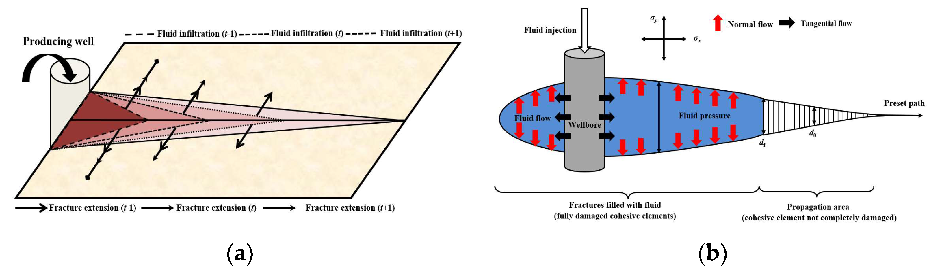
Figure 5.
Variations of fracture half-length and infiltration radius under different injection times.
Figure 5.
Variations of fracture half-length and infiltration radius under different injection times.
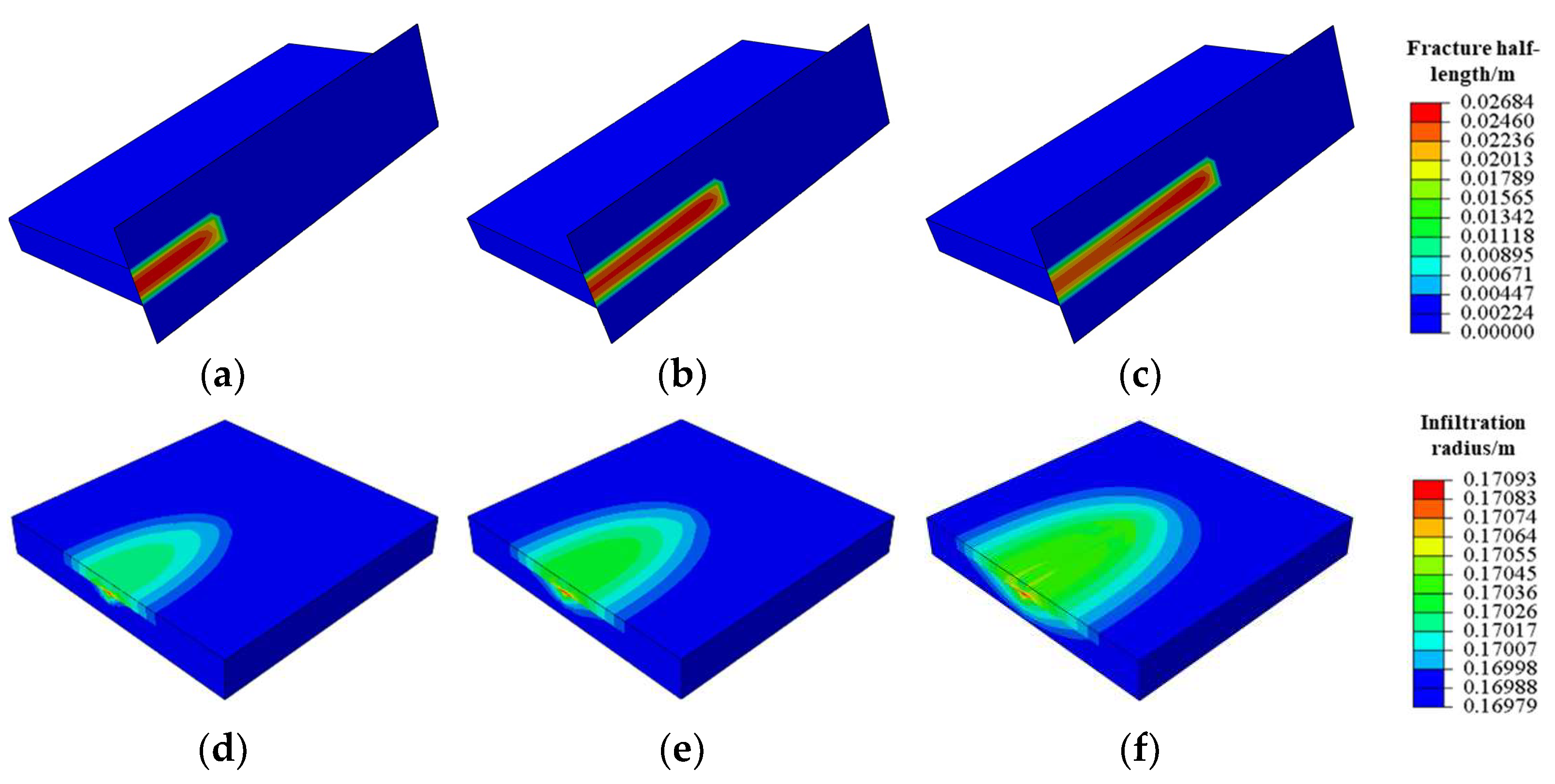
Figure 6.
Time-dependent variation of fracture half-length and infiltration radius under different reservoir thicknesses. (a) Fracture half-length vs. time; (b) Infiltration radius vs. time.
Figure 6.
Time-dependent variation of fracture half-length and infiltration radius under different reservoir thicknesses. (a) Fracture half-length vs. time; (b) Infiltration radius vs. time.
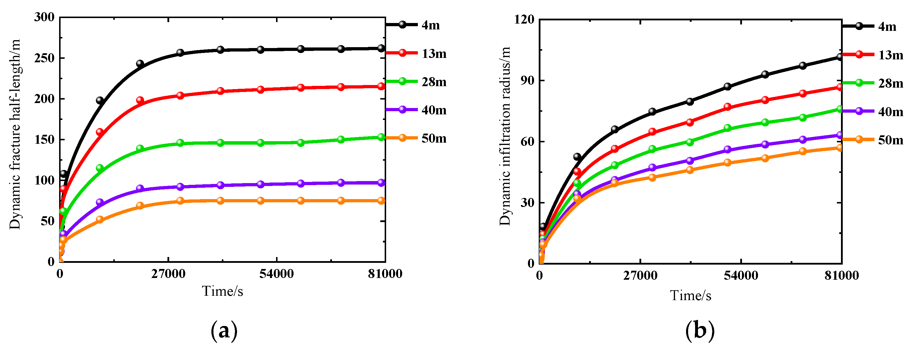
Figure 7.
Time-dependent variation of fracture half-length and infiltration radius under different permeability. (a) Fracture half-length vs. time; (b) Infiltration radius vs. time.
Figure 7.
Time-dependent variation of fracture half-length and infiltration radius under different permeability. (a) Fracture half-length vs. time; (b) Infiltration radius vs. time.
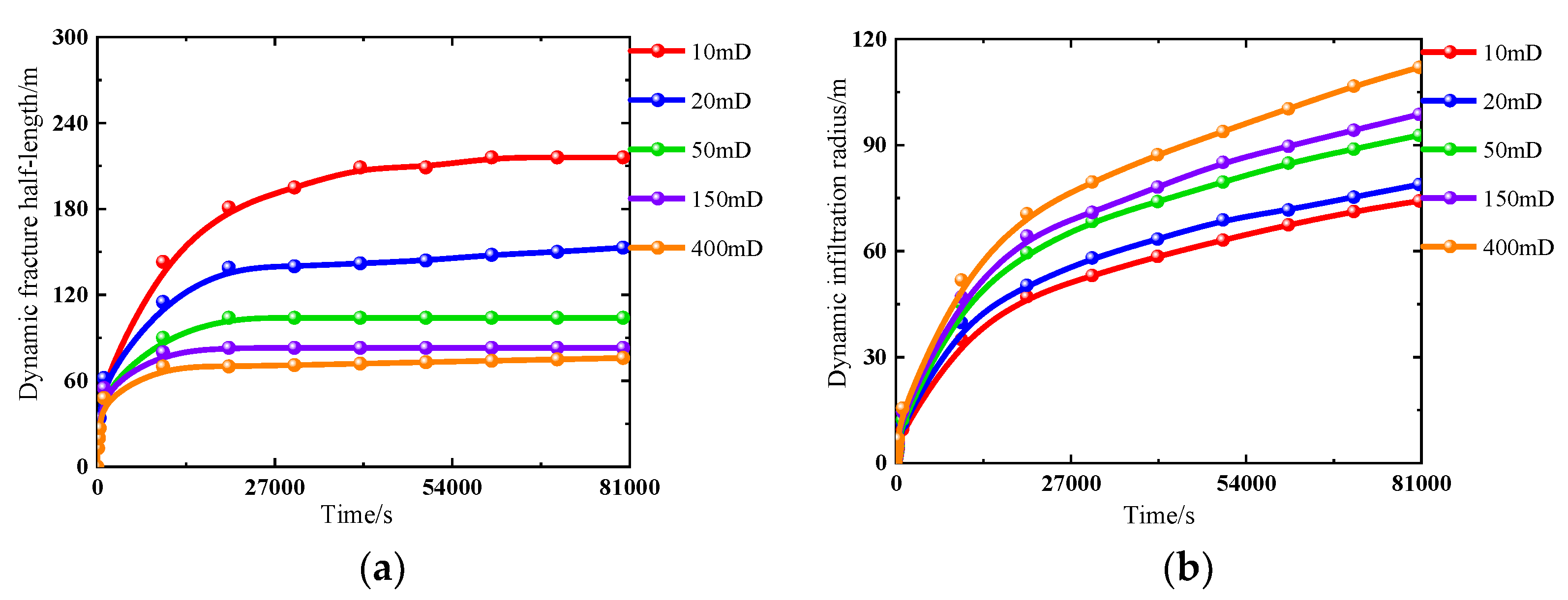
Figure 8.
Time-dependent variation of fracture half-length and infiltration radius under different formation pressure coefficient before HFAOD. (a) Fracture half-length vs. time; (b) Infiltration radius vs. time.
Figure 8.
Time-dependent variation of fracture half-length and infiltration radius under different formation pressure coefficient before HFAOD. (a) Fracture half-length vs. time; (b) Infiltration radius vs. time.
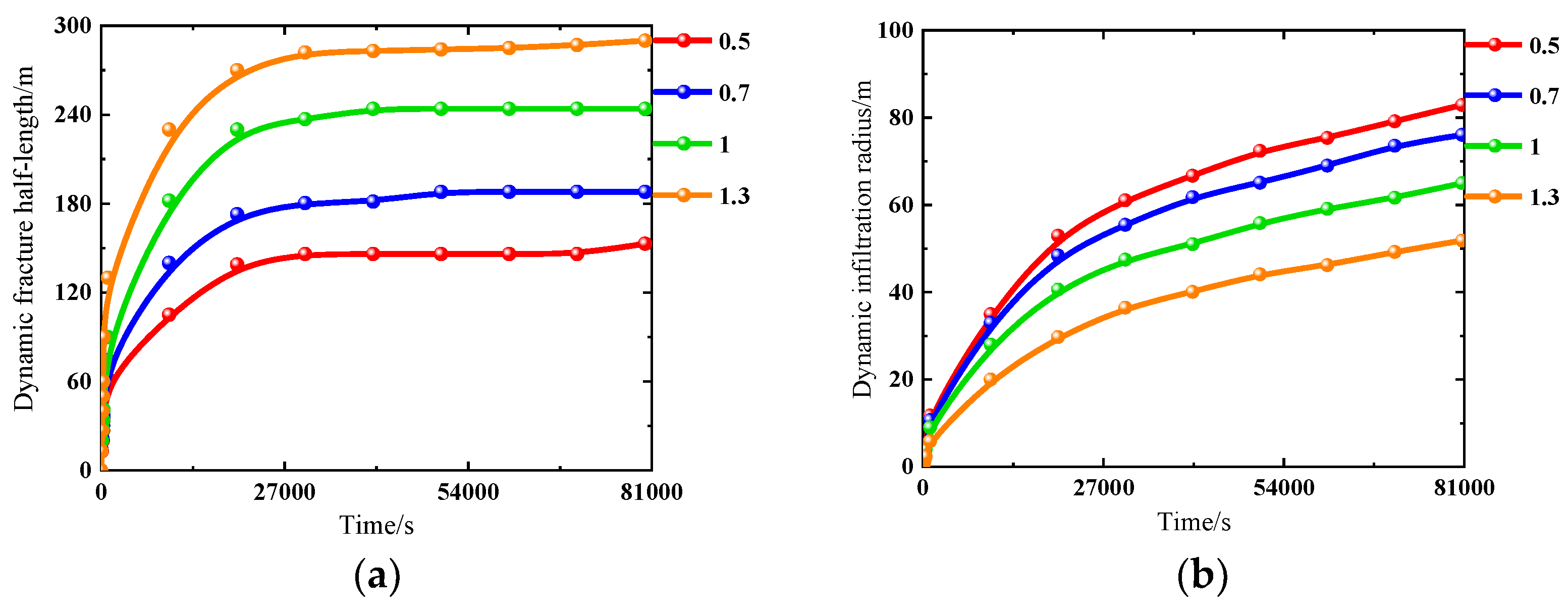
Figure 9.
Time-dependent variation of fracture half-length and infiltration radius under different injection rate. (a) Fracture half-length vs. time; (b) Infiltration radius vs. time.
Figure 9.
Time-dependent variation of fracture half-length and infiltration radius under different injection rate. (a) Fracture half-length vs. time; (b) Infiltration radius vs. time.
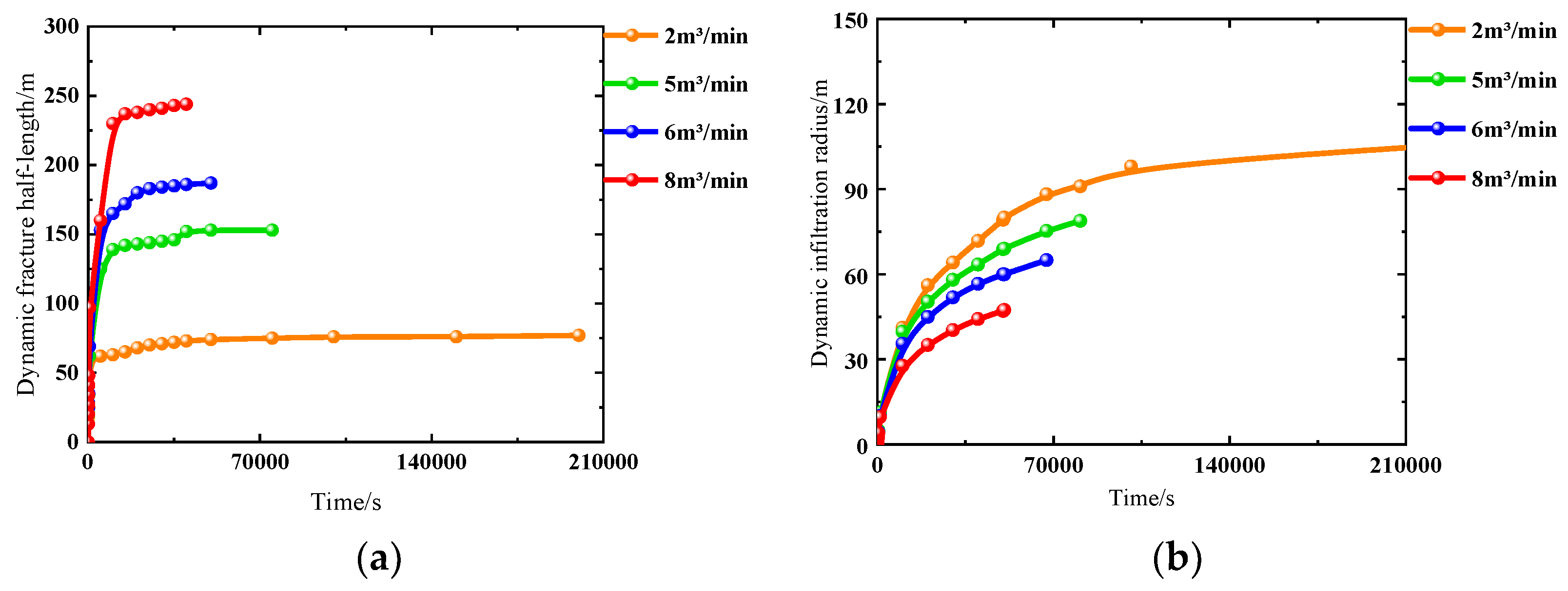
Figure 10.
Time-dependent variation of fracture half-length and infiltration radius under different viscosity. (a) Fracture half-length vs. time; (b) Infiltration radius vs. time.
Figure 10.
Time-dependent variation of fracture half-length and infiltration radius under different viscosity. (a) Fracture half-length vs. time; (b) Infiltration radius vs. time.
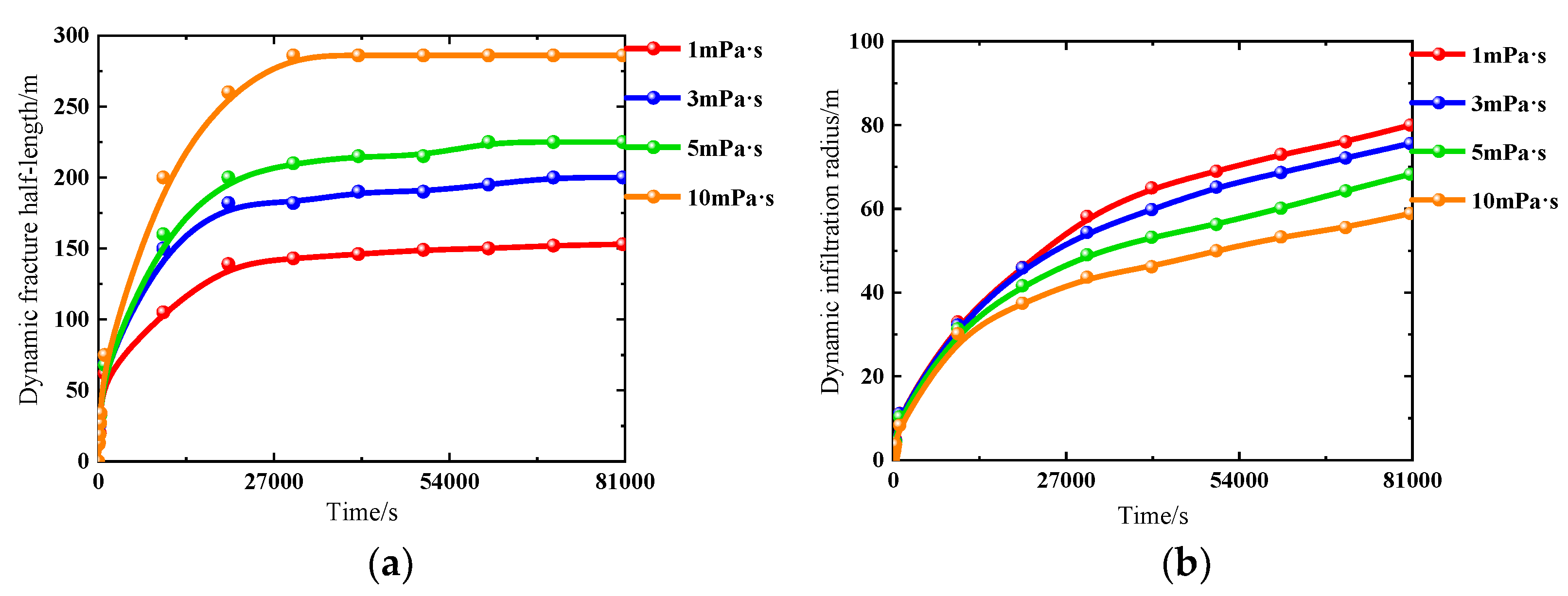
Figure 11.
Time-dependent variation of fracture half-length and infiltration radius under different cumulative injection volume. (a) Fracture half-length vs. time; (b) Infiltration radius vs. time.
Figure 11.
Time-dependent variation of fracture half-length and infiltration radius under different cumulative injection volume. (a) Fracture half-length vs. time; (b) Infiltration radius vs. time.
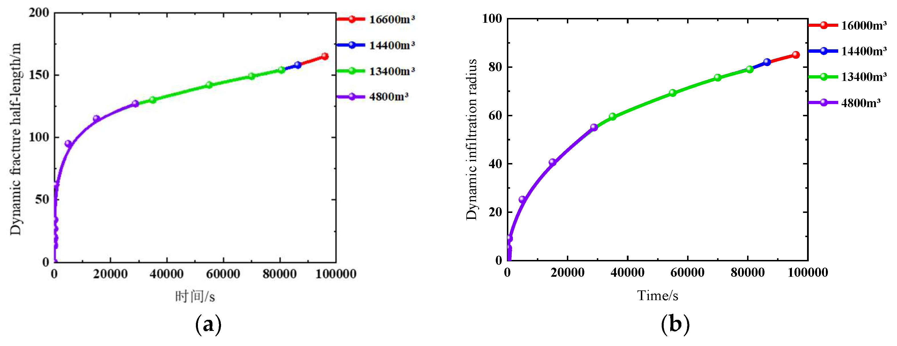
Figure 12.
Composite plot. (a) Fracture half-length optimization chart; (b) Infiltration radius optimization chart.
Figure 12.
Composite plot. (a) Fracture half-length optimization chart; (b) Infiltration radius optimization chart.
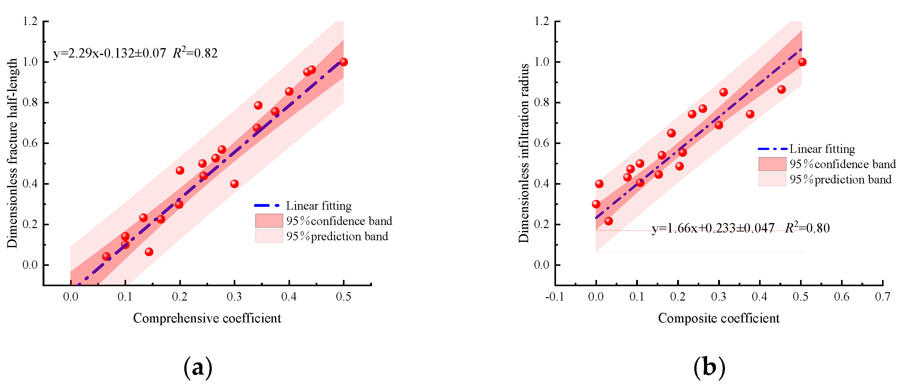

Table 1.
Reservoir rock mechanics and construction parameters.
| Parameters | Reservoir | Interlayer |
|---|---|---|
| Young's modulus/(GPa) | 26 | 18 |
| Poisson's ratio | 0.24 | 0.32 |
| Tensile strength/(MPa) | 5 | 6 |
| Fluid infiltration coefficient/(m∙s1/2) | 2.56E-13 | 2.56E-14 |
| Formation stress/(MPa) | 41,50 | 45,54 |
| HFAOD fluid viscosity/(Pa∙s) | 0.001 | |
| Injection rate/(m3/s) | 0.08 | |
Table 2.
Scheme of sensitivity analysis.
| Influencing factors | Scheme | Parameters | Fracture half - length/(m) | Infiltration radius/(m) | |
|---|---|---|---|---|---|
| Geological factors | Thickness/(m) | 1 | 4 | 262 | 102 |
| 2 | 13 | 215 | 87 | ||
| 3 | 28 | 153 | 76 | ||
| 4 | 40 | 97 | 63 | ||
| 5 | 50 | 75 | 57 | ||
| Permeability/(mD) | 6 | 10 | 216 | 74 | |
| 7 | 20 | 153 | 79 | ||
| 8 | 50 | 104 | 93 | ||
| 9 | 150 | 83 | 99 | ||
| 10 | 400 | 76 | 112 | ||
| Formation pressure coefficient before HFAOD | 11 | 0.5 | 153 | 79 | |
| 12 | 0.7 | 188 | 73 | ||
| 13 | 1 | 244 | 65 | ||
| 14 | 1.3 | 290 | 52 | ||
| Construction factors | Injection rate/(m3/min) | 15 | 2 | 77 | 105 |
| 16 | 5 | 153 | 79 | ||
| 17 | 6 | 187 | 65 | ||
| 18 | 8 | 244 | 47 | ||
| Viscosity/(mPa·s) | 19 | 1 | 153 | 79 | |
| 20 | 3 | 200 | 76 | ||
| 21 | 5 | 225 | 68 | ||
| 22 | 10 | 286 | 59 | ||
| Cumulative injection volume/(m3) | 23 | 4800 | 125 | 55 | |
| 24 | 13440 | 153 | 79 | ||
| 25 | 14400 | 158 | 82 | ||
| 26 | 16000 | 165 | 85 |
Table 3.
Weight calculation results of main control factors for pressure-driven fracture half-length.
Table 3.
Weight calculation results of main control factors for pressure-driven fracture half-length.
| Parameters | Cumulative injection volume (m3) | Thickness (m) | Injection rate (m3/min) | Formation pressure coefficient | Permeability (mD) | Viscosity (mPa∙s) |
|---|---|---|---|---|---|---|
| Weigh of fracture half-length | 0.1329 | 0.2462 | 0.2046 | 0.1621 | 0.1364 | 0.1579 |
| Weigh of infiltration radius | 0.1199 | 0.0975 | 0.1642 | 0.2038 | 0.2999 | 0.1145 |
Disclaimer/Publisher’s Note: The statements, opinions and data contained in all publications are solely those of the individual author(s) and contributor(s) and not of MDPI and/or the editor(s). MDPI and/or the editor(s) disclaim responsibility for any injury to people or property resulting from any ideas, methods, instructions or products referred to in the content. |
© 2025 by the authors. Licensee MDPI, Basel, Switzerland. This article is an open access article distributed under the terms and conditions of the Creative Commons Attribution (CC BY) license (http://creativecommons.org/licenses/by/4.0/).
Copyright: This open access article is published under a Creative Commons CC BY 4.0 license, which permit the free download, distribution, and reuse, provided that the author and preprint are cited in any reuse.


