
Submitted:
28 April 2025
Posted:
29 April 2025
You are already at the latest version
Abstract
PV panels has been proven to be a good renewable energy source. However, excessive heat of the panel can lead to degradation of the longevity of the panel. Crucial determinants impacting the effectiveness of PV panels encompass the type of materials, temperature, and the level of solar radiation received. Thus, cooling is required to overcome this issue which leads to improved electrical efficiency and lifespan of the panel. This study provides an overview of different techniques that can be employed to mitigate the adverse effects of elevated temperatures while simultaneously improving the performance of photovoltaic solar panels operating above the recommended temperature of the Standard Test Conditions (STC). The objective of this review is to enhance comprehension of the mentioned technologies in order to decrease the surface temperature of the PV module. Cooling methods that are reviewed are heat exchanger, nanofluids and phase change material (PCM). The review and classification of many research publications is conducted based on their specific focus, contribution, and the sort of technology employed to facilitate the cooling of photovoltaic panels. Each of these systems is exemplified with precise schematics and extensively examined and compared. Moreover, this work presents a novel categorization system for the cooling techniques employed in photovoltaic panels, providing useful direction for future investigations and enhancing efficiency. The findings of this review shows that heat exchanger with higher flowrate has better higher temperature improvement. Moreover, different heat exchanger pipes shapes resulted in different cooling efficiency outcome. Hybrid nanofluids shows higher temperature drops compared to nanofluid with water. Addition of porous material to PCM resulted in a lower melting point thus cooling occurs faster compared to regular PCM.
Keywords:
photovoltaic panel
; heat exchanger
; nanofluid
; phase change material
1. Introduction
Solar thermal collectors and photovoltaic panels are considered advantageous for capturing and converting solar energy into usable energy because of the plentiful and limitless nature of the solar resource [1]. The photovoltaic module converts a portion of sunlight into electrical energy due to the photoconversion effect. Approximately 80% of the solar radiation absorbed by the photovoltaic panel is not converted, leading to an increase in operating temperature, resulting in decreased efficiency and aging [1]. Uncooled panel has shown to perform less efficiently with an average electrical efficiency of 9.15%, while the cooled panel had an average efficiency of 10.40% [2]. This demonstrates the evident advantages of active cooling in improving the performance of solar panels. PV cells operating in intense sunshine and high temperatures, such as in tropical or desert areas or during summer in temperate zones, typically experience greater efficiency reduction [3]. For every 1 °C increase in surface temperature of the PV module, there is a 0.5% decrease in efficiency [4]. In addition to the various benefits of PV technology, this kind of conversion system is susceptible to issues like hail, dust, and surface operating temperature, which can reduce its efficiency [5]. Thus, not all solar energy collected by photovoltaic cells is transformed into electrical energy due to the temperature increase. The excess solar energy is transformed into heat to comply with the law of conservation of energy. This squandered heat results in a decrease in the total conversion efficiency. Enhancements in efficiency are necessary for solar energy conversion technologies to become a practical renewable energy alternative. In order to create a feasible solution, it is necessary to explore several methods to address the temperature issue, leading to an enhancement in the overall effectiveness of conversion. Researchers are exploring various cooling methods to improve the efficiency and cost-effectiveness of photovoltaic panels, aiming to capitalize on the benefits of enhanced energy efficiency, cost reduction, and environmental preservation associated with advancements in photovoltaic cell performance. This increase in attention has created [6]. In the future, it will be crucial to have in-depth review papers that summarize contemporary cooling solutions to push this topic further. Some studies have concentrated on certain methodologies, as the research conducted by Ali [7] regarding phase change materials, Suresh et al., [8] regarding nanofluids as coolants, Bhakre et al., [9] discussed water cooling. Preet [10] about water and PCM cooling, Othman et al., [11] regarding air conditioning, Kane et al., [12] conducted research on thermoelectric cooling, while Elbreki et al., [13] also contributed to the field on photovoltaic cooling using passive cooling. Bahaidarah et al., [14] discussed uniform cooling, while Siah Chehreh Ghadikolaei [15] provided a detailed analysis of cooling methods, excluding thermoelectric and evaporative cooling methods.
This paper aims to offer a thorough and current examination of modern cooling methods for solar systems, emphasizing their crucial role in enhancing both the sustainability and effectiveness of these systems. The inquiry delves into many views and categorizations of sophisticated cooling methods, such as heat exchangers, nanofluids, and phase change materials.
2. Methodology
This section will explain the operational principle of various technologies that can mitigate the impact of increased temperature on a PV panel operating above the recommended temperature of the Standard Test Conditions (STC). The technical explanation aims to facilitate the understanding of relevant research findings from various authors.
2.1. Photovoltaic Panel Cooling Using Heat Exchanger
A closed-loop system is typically used to establish a cooling system for photovoltaic panels with a heat exchanger. This entails connecting a network of cooling pipes or tubes directly to the rear of the PV panels, through which a cooling fluid, typically water or a glycol mixture, flows. The heat exchanger is incorporated into this circuit. The solar panels capture heat from sun and transfer it to the fluid flowing through the pipes. Next, the warm fluid is directed to the heat exchanger, where it is cooled through heat exchange with the surrounding environment or another cooling medium. The fluid returns to the panels after cooling to absorb more heat, thus maintaining the temperature of the solar panels and improving their efficiency. This technology not only maintains ideal operating conditions for solar panels but also uses the gathered heat for additional purposes like heating water or spaces, enhancing total energy efficiency. Figure 1 and 2 shows the experimental setup and schematic diagram of photovoltaic panel cooling using heat exchanger [16].
Nasir et al., [17] conducted an experiment centered around a model of water cooling pipework on the backside of the PV panel. Copper pipes with a high thermal conductivity of approximately 385 W/m-K, were formed into elliptical shapes as in Figure 3 and attached to the backs of PV panels to serve as heat exchangers. The benefit of using a particular elliptical copper pipe cooling model is that it reduces the temperature gradient across the panel. The schematic diagram of the setup and the experimental setup is shown in Figure 4 and Figure 5 respectively.
Jakhar et al., [18] created an experimental configuration for a PV/T system connected to a ground-coupled heat exchanger(GCHE) in Pilani, Rajasthan, India. This configuration was utilized for trials to assess the system’s performance. The schematic setup is showed in Figure 6. The front cross-section view of the PV/T panel is shown in Figure 7.
The prototype system was created with a mono-crystalline silicon photovoltaic panel, an artificial solar system, a repository, and a data gathering system. The PV panel had a total size of 780 square millimeters and had 72 cells. The setup consisted of a solar simulator with metal halide lamps, a thermometer, 12 K-type thermocouples, an electrical load for recording voltage and I-V data, a container for liquid PCM underneath the PV panel, and a finned copper-tube heat exchanger [19]. Figure 8 displays a schematic design of the setup, including a mono-crystalline silicon photovoltaic panel, artificial solar system, repository, and data attainment system [19].
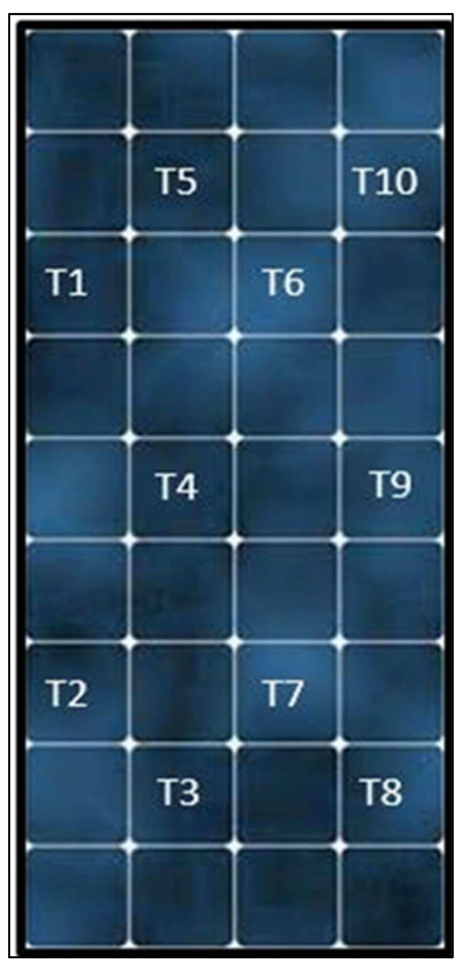
The photovoltaic panel had an inclination angle of 18°, and cold water was introduced through the bottom entrance of the heat exchanger. Designated amounts of PCM were introduced into the container, and the cooling water flow rate was adjusted correspondingly. Temperature was measured at 12 specific locations on the surface of the PV panel, in addition to collecting voltage and I-V data [19]. Each PV panel matrix has an effective area of 30 mm x 26 mm and contains 72 well-functioning cells as shown in Figure 9.
Fabbri & Greppi [20] undertook a study to create a numerical model for simulating the performance of an integrated photovoltaic-thermoelectric (PV-TE) module. The model is finite and steady-state, created to numerically replicate the module’s performance under specific conditions.
An new cooling approach is suggested in Figure 10, which simplifies solar cell cooling and thermoelectric conversion technology by combining the heat exchanger with the thermoelectric converter, utilizing the Seebeck effect. The heat exchanger also serves as a structural support for the cells [20].
An experimental evaluation of a photovoltaic thermal (PVT) system, supplemented by an underground heat exchanger (UHE), is conducted in Baghdad, Iraq during tough summer weather conditions [21]. This setup intends to evaluate the practicality and effectiveness of utilizing an underground heat exchanger to cool a PVT system, perhaps enhancing its electricity output in areas with severe weather conditions [21]. A 3U-shaped copper tube heat exchanger, 22.25 meters long and with strong thermal conductivity, was buried 4 meters deep. The depth was selected after initial research showed consistent ground temperatures that are suitable for effective heat dispersion. Figure 11 shows the area where the experiment was conducted, the heat exchanger which was used and how the thermocouple was distributed on the Underground Heat Exchanger (UHE).
Two monocrystalline PV modules were utilized, one operating as a conventional PV system and the other enhanced with a spiral heat exchanger on the rear side. The panels were tilted at a 33° angle facing south [21]. Thermocouples were used to monitor the temperatures at the entrance and output of the heat exchanger, while a water pump regulated the flow rate of the cooling water through the system [21].
The study proposed by Saftoiu & Morega [22] a dual cooling technique for photovoltaic (PV) panels to improve efficiency by lowering operating temperatures, which can negatively impact performance. The technology included a water-circulated counter-current heat exchanger and a unique pulsed fluid cooling system, both located on the back of the panel. The counter-current heat exchanger efficiently distributed cooling fluid over the panel to constantly remove heat, while the pulsed cooling system injected cooling fluid periodically to manage peak thermal demands dynamically. Numerical simulations were used to model these systems to evaluate their capacity to reduce temperatures and improve the electrical efficiency of the PV panel. The models quantified the enhancements in temperature regulation and the possible reuse of captured thermal energy in secondary energy conversion cycles, enhancing overall energy management [22]. This system has counter-current flow pipes on the rear face of the PV, as seen in Figure 12.
The study implemented an innovative cooling system for photovoltaic (PV) panels to enhance energy efficiency by integrating a minichannel cooler and a geothermal system [23]. In this methodology, PV cells were directly bonded to a polymer minichannel heat exchanger during panel fabrication, using Ethylene Vinyl Acetate (EVA) as an adhesive, which minimizes thermal contact resistance. The heat exchanger, designed with minichannels to increase the surface area for effective heat transfer, facilitated the removal of heat from the PV cells. This extracted heat was then dissipated using a geothermal cooling system, where coolant circulated through underground plastic pipes leveraged the stable subterranean temperatures as a natural cooling medium. Temperature measurements were conducted with thermocouples and thermal imaging to assess the efficacy of this cooling approach in maintaining optimal PV cell temperatures, thereby enhancing their electrical output and efficiency. Additionally, an economic analysis was performed to evaluate the cost-effectiveness of the system by comparing the levelized cost of energy (LCOE) with conventional cooling methods [23].
Photovoltaic cells in modern PV panels are attached to tempered glass using EVA glue. EVA additionally bonds the cells to Tedlar backsheet for environmental protection. The materials are stacked in layers and crushed using a vacuum, then assembled in around 15 minutes at a temperature of around 140 degrees Celsius. In our model, the fabrication process remains the same, with the only alteration being the attachment of the cooler directly behind the photovoltaic solar cell using EVA, as seen in Figure 13.
The panel linked to a geothermal cooling system includes plastic pipes buried underneath. To minimize installation costs and space requirements, the geothermal heat exchanger is designed in a coil shape, which is the standard configuration for sale [23]. Figure 14 depicts the schematic diagram of the system.
The study performed a numerical analysis to enhance the efficiency of photovoltaic (PV) panels by using cooling techniques, particularly for panels integrated into vented facades of structures using TRNSYS computer software [24]. The emphasis was on optimizing the fixed location of the panels and improving their conversion efficiency through temperature control. The proposed cooling method entailed attaching water heat exchangers to the rear of the PV panels. Figure 15 displays the numerical model.
The study by Siddiqui et al., [25] describes a detailed analysis and practical assessment of an innovative heat exchanger design intended for cooling photovoltaic (PV) panels. The approach combines computational fluid dynamics (CFD) modelling with experimental particle image velocimetry (PIV) to enhance and evaluate different heat exchanger designs. The CFD model initially evaluated the effects of several design factors, including channel counts, manifold width, and the position and form of inlet/exit ports. Fourteen designs were created to maximize the top surface temperature, temperature uniformity, and heat transfer efficiency in relation to pumping power. The top-performing designs were built and tested using Particle Image Velocimetry (PIV) to assess flow dispersion and confirm the accuracy of the Computational Fluid Dynamics (CFD) model predictions. Variety of design are selected for optimization as shown in Figure 16.
The summary of cooling PV panels using heat exchanger is illustrated in Table 1.
2.2. Photovoltaic Panel Cooling Using Nanofluid
Nanofluid is used to improve the heat transfer qualities of the cooling fluid in photovoltaic panels by adding nanoparticles to a base fluid such as water or glycol. Nanofluids consist of particles usually composed of metals or metal oxides like copper, aluminum, or titanium dioxide, and have enhanced thermal conductivity and heat transfer properties in comparison to conventional fluids. Nanofluids, when passed via a cooling system connected to PV panels, effectively absorb and remove heat from the panels because of their improved thermal characteristics. This leads to a decrease in the surface temperature of the PV panels, which helps to maintain or maybe enhance their electrical output efficiency. Utilizing nanofluids for cooling PV panels is an innovative method that leverages nanotechnology to mitigate the decrease in efficiency that solar panels face in high temperature environments. Figure 17 shows the procedure to prepare nanofluid.
The configuration had a single-crystal PV panel with a spiral tube collector connected to its rear side. The setup enabled the nanofluid to pass through the collector, extracting surplus heat from the PV panel. A comparison was made between the performance of this setup, a standalone PV panel as shown in Figure 18, and a PV/T system that was cooled using only water as shown in Figure 19 [29].
Qeays et al., [30] conducted a study with the configuration comprises a 300W polycrystalline silicon photovoltaic module with copper tubes positioned beneath the PV cells for cooling. Nanofluid flows through the tubes to lower the surface temperature of the PV system. A counterflow shell-and-tube heat exchanger design is used to cool the nanofluid after heating. Temperatures are gauged with K-type thermocouples and an infrared thermometer. The electrical circuit consists of charge controllers, storage batteries, and a DC load to maintain uninterrupted electricity generation [30]. The schematic diagram of the experimental setup is shown in Figure 20.
Bayoumi et al., [31] uses Comsol Multiphysics software, a Finite Element Method (FEM), and Matlab for simulations, specifically concentrating on an electro-thermal model of the PV panel. A PV/T system model is developed to investigate the impact of various back pipe configurations installed beneath the PV module. The structures consist of a serpentine shape and a newly suggested square shape, selected for their ability to enhance the efficiency of heat transfer and the efficiency of conversion as shown in Figure 21.
Khalili et al., [32] integrated a thermoelectric generator (TEG) layer with traditional layers of photovoltaic-thermal (PVT) modules to make use of waste heat and enhance efficiency. The PVT-TEG unit utilized a cooling duct at its base to lower the cell temperature, with the choice of fluid and duct design influencing system efficiency. The combination layer of PVT and TEG is shown in Figure 22.
Three distinct duct shapes (circular, rhombus, and elliptic) were examined as shown in Figure 23 [32].
A numerical simulation technique was used in a research that investigated the cooling of a photovoltaic (PV) solar panel with Al2O3-water nanofluid [33]. The technique focused on using the finite element method (FEM) to solve the Navier-Stokes and energy conservation equations that control the fluid dynamics and heat transfer processes between the solar panel and the nanofluid. Figure 24 displays the arrangement utilized in this investigation.
The work by Shahad et al.,[34] utilized experimental and theoretical methods to examine the effects of employing SiC/Water nanofluid as a coolant on the efficiency of photovoltaic/thermal (PV/T) panel systems. The experimental setup had monocrystalline PV panels that were altered to include a cooling system constructed from 3mm thick aluminium, which was affixed to the back of the panels. A theoretical model of this configuration was created in SolidWorks and analyzed using ANSYS 18.2 to forecast the system’s performance under different circumstances [34].
Three identical monocrystalline photovoltaic modules were built and deployed at Babylon University campus in Iraq (32.46 °N, 44.42°E). Two of the PV modules were altered to include a pocket aluminium collector, one cooled with SiC/Water nanofluid and the other with pure water. The third PV module’s back sheet was cooled by the surrounding air, as seen in Figure 25. The nanofluid was pumped and cooled using a helical heat exchanger, as seen in Figure 26. The tilt angle was modified monthly based on the inclination angle, while the PV modules were oriented towards the south (zero azimuth angle). Figure 26 and Figure 27 display the schematics of the rig.
There are a total of 12 thermocouples placed evenly throughout each photovoltaic cell surface to detect temperature. Two fabricated heat exchangers made of straight metal rectangular tubes are utilized to cool the PV cells. The design has 23 parallel channels made of aluminium with measurements of 24.5 cm in length, 5 mm in width, and 3.5 mm in depth. All channels have the same rectangular entry cross-section, as seen in Figure 28 [35].
Figure 29 and Figure 30 display the setup and schematic diagram of the entire experimental equipment. PV cells 1 and 2 in the experimental setup are cooled using nanofluids and water, respectively, with the help of two circulating centrifugal pumps. The third photovoltaic cell operates without cooling [35].
The summary of cooling PV panels using nanofluid is illustrated in Table 2.
2.3. Photovoltaic Panel Using Phase Change Material
Phase change materials (PCMs) provide a passive and effective thermal management solution when used to cool photovoltaic (PV) panels. Phase change materials (PCMs) are incorporated within the solar panel system, often positioned behind the panels to efficiently capture surplus heat. These materials experience a phase transition at precise temperatures, transitioning between solid and liquid states, and absorb or release significant amounts of heat in the process. The phase change material absorbs heat as it melts, which keeps the solar panels at a lower and more consistent temperature. This process optimizes their efficiency by reducing the performance decline usually caused by high temperatures. As temperatures decrease, the phase change material solidifies, releasing the stored heat and getting ready for the next cycle, thus maintaining the system’s efficiency without requiring external energy inputs.
Figure 31 displays the schematic representation drawn in SolidWorks of the implementation of PCM in cooling photovoltaic panel [39].
The phase change material was placed in an 80°C water bath to progressively melt the salt hydrate. Subsequently, the melted PCM was poured into the container as shown in Figure 32(a). The heat exchanger component was affixed to the container to seal it from the air’s harmful impact on the PCM. Figure 32(b) displays the completed arrangement, positioned on the 30-degree angle mounting framework, aligned with the longitude of Tehran city [39].
Figure 33 displays the electrical circuit used to measure the maximum power output of the PV/T device [39].
Kiwan et al., [40] conducted a study involving both theoretical modelling and experimental setup. The researchers utilized mathematical formulations based on thermal resistance and energy balance concepts to predict the performance of PV systems with and without PCM cooling. Two identical PV panels were deployed outdoors for empirical testing, one with PCM attached to its back and the other without PCM for comparison. The PCM used was paraffin graphite panels, known for good thermal conductivity, covered with an aluminium sheet to enhance heat dissipation [40].
The experimental system included solar photovoltaic panels, an inverter, a control unit, and batteries as shown in Figure 34.
This study used Ansys Fluent software to conduct unsteady numerical simulations. It utilized a two-dimensional simplified geometry for both the regular PV module and the PV module integrated with PCM (PV-PCM) [41]. Two different types of PCM was used in this study which are Rubitherm 28 HC (PV-PCMRT28) and Rubitherm 35 HC (PV-PCMRT35) both has melting point of 27 to 29°C and 34 to 36°C respectively [41]. The PV-PCM modules are made of five different layers which are glass glass cover, PV cells, two EVA sheet (EVA-PV-EVA), Tedlar, PCM material and another two plates of PCM tank as shown in Figure 35.
The study conducted by Badi et al., [42] focused on improving the effectiveness of solar panels by utilizing a phase change material (PCM-OM37P) to regulate panel temperatures close to ambient values. The study was place at the Renewable Energy and Energy Efficiency Center (REEEC) at the University of Tabuk. Three identical solar systems, totalling 9 kW in capacity, were monitored from a remote location. PCM packs were affixed to the rear of the solar panels to collect surplus heat throughout the day, then releasing it later to lower the working temperature of the panels and enhance their efficiency [42]. The University of Tabuk Renewable Energy and Energy Efficiency Center (REEEC) showcased improved photovoltaic efficiency on three identical solar systems at their location, each with a capacity of 3kW, totalling 9kW. Refer to Figure 36 for further details.
Approximately 60 BioPCM packs, each measuring 128 x 153mm and weighing 150g, were attached to the rear of the PV panel using a both sides thermal conductive and strong acrylic glue. The packs are constructed of fiberglass with conductive ceramic powder form, as seen in Figure 37.
The study conducted by Rajaee et al., [43] improved the performance of a photovoltaic/thermoelectric generator (PV/TEG) hybrid system by experimentally utilizing cobalt oxide nanofluid and phase change material (PCM) as cooling agents. Figure 38 displays the design of the experimental setup and the PV/TEG configuration. The photovoltaic panel absorbs solar irradiance.
Five k-type thermocouple sensors were used in this configuration to measure various temperatures. The initial sensor was positioned on the external surface of the photovoltaic (PV) system to monitor the temperature of the PV cell’s surface. The second sensor was placed at the rear of the photovoltaic cell. The third sensor was connected to the cool side of the Thermoelectric Generator (TEG). The remaining sensors recorded the temperatures of the input and output fluids, allowing for a straightforward calculation of the heat absorbed by the coolant fluid. A tiny pump with little power consumption was used to circulate the cooling liquid in the integrated system. Moreover, all components were connected to each other using heat conductive paste. Figure 39 shows the snapshot of the experimental setup [43].
The experimental study concentrated on implementing several cooling methods for photovoltaic (PV) panels to enhance their efficiency and power generation [44]. The approaches examined involved the utilization of phase change material (PCM), thermoelectric modules (TEM), and aluminum fins. Figure 40 displays an overall perspective of the experimental arrangement [44].
The study monitored the surface temperatures of the solar panels and outside temperatures using a 0.51 mm diameter T-type thermocouple from OMEGA. Ten thermocouples were utilized in the studies, and their positions are illustrated in Figure 42 [44].
Figure 41.
Displays the arrangement of the thermocouples on the photovoltaic panels.
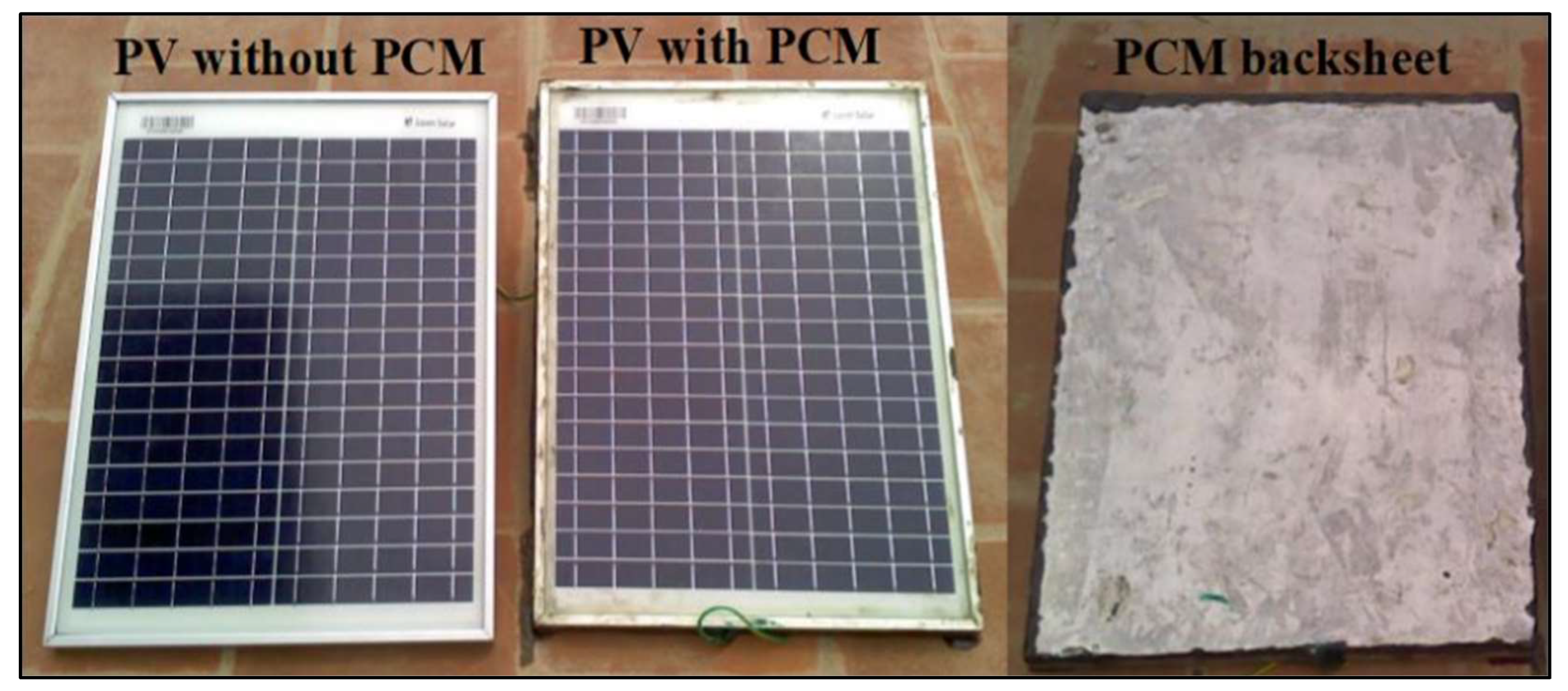
The study’s approach included an experimental setup using two similar 20 Wp polycrystalline PV modules, one containing Phase Change Material (PCM) and one without [45]. The PCM utilized was OM29, a commercial organic substance placed directly on the back of the PV module to improve heat transmission by removing the conduction barrier caused by an intermediary layer. The back of the PCM was covered with a composite material of tin and aluminum to avoid leaks during the phase transition [45].
Two identical 20 Wp polycrystalline PV modules from Loom solar, measuring 450 mm × 350 mm × 22 mm, were utilized in the experiment. One module was employed for PV without PCM, and the other for PV with PCM, as seen in Figure 42. 2.8 kilos of liquid OM29 PCM was put on the backside of the PV module with 5% room reserved for volume change during phase transition or expansion. The rear side of the PCM was sealed using a 0.5-mm tin coupled with an aluminium sheet to prevent leakages during phase transition [45].
Figure 42.
Experimental configurations for photovoltaic panel with and without PCM utilizing OM29.
The study by Jamil et al., [46] utilized a technique that includes an experimental setup to assess the performance improvements resulting from adding nano phase change materials (nano-PCMs) in solar panels under different situations. The trials was place outside at the University of Engineering and Technology in Taxila, Pakistan. Three distinct nano-PCMs were created by combining multiwall carbon nanotubes, graphene nanoplatelets, and magnesium oxide nanoparticles with a phase change material known as PT-58. Nano-PCMs were used on solar panels at concentrations of 0.25 wt% and 0.5 wt%. The PV panels with nano-PCMs were compared to traditional PV panels lacking nano-PCMs. The measurements were concentrated on metrics like temperature reduction and increase of electrical efficiency. Figure 43 shows the present experimental setup for the study endeavor [46].
The experimental setup primarily included four PV modules, a Data Acquisition System (34972A, Agilent, USA), and a Solar Module Analyzer (PROVA 210). Figure 44 displays the schematic depiction of the experimental setup [46].
The study used a 1-D thermal resistance model in MATLAB to evaluate the performance of photovoltaic-phase change material (PV-PCM) systems over the course of a year [47]. The model utilized an improved conductivity approach to estimate convective heat transfer effects without the need to solve intricate Navier-Stokes equations, enabling rapid and expedited simulations ideal for prolonged investigation. Various phase change materials (PCMs) with different melting temperatures were assessed in five unique PV-PCM system setups. The simulations utilized actual meteorological data from Shanghai in 2017 to evaluate how variations in electrical efficiency across the seasons and year are influenced by variances in PCM characteristics and environmental conditions. The method enabled a thorough examination of how PCM properties, weather fluctuations, and solar system efficiency interacted across a whole year [47].
Figure 45 displays the setup of the PV-PCM system. The PV panel is divided into five layers: glass, EVA, PV cells, and TPT, for illustrative purposes. The photovoltaic panel is in direct contact with phase change material (PCM) enclosed in a chamber made of polypropylene (PP) plates [47].
Figure 46 displays the experimental design. The PV panel is linked to a battery and a dump load to facilitate the transmission and consumption of the generated power. An MPPT controller is integrated into the electrical system to ensure the PV system consistently functions at its peak power point. The PV temperature and PCM temperature are measured using PT-100 temperature sensors [47].
The summary of cooling PV panels using nanofluid is illustrated in Table 3.
3. Economical Advantages
Closed-loop pulsing heat pipe (CLPHP) for the purpose of cooling photovoltaic (PV) panels offers significant cost benefits. The CLPHP-based cooling system offers a more cost-effective solution for operation and maintenance as compared to conventional water-based flat plate cooling systems. The absence of energy-consuming components such as pumps or fans, which are essential for conventional active cooling techniques, is the reason behind the energy efficiency of the CLPHP system [52]. The payback period of the investment calculated shows that water-based cooling method has better cooling but with longer payback period which is 14.5 years compared to active CLHP cooling which is 13 years [52].
An average payback period for uncooled PV panel ranges around 1.9 years according to Figure 47 [53]. The more complex the cooling element the better the efficiency of the panel. The benefits of superior cooling far outweighs the cost due to longer lifespan of the panel.
The water-based cooling systems demonstrated the highest energy production, with an average of 32.29 kWh, resulting in cost savings of around USD 0.273. Thermoelectric cooling has proven to be the most efficient method, with an average energy output of 34.512 kWh and resulting in the greatest cost reduction. This is especially notable in the month of July, where the average cost savings amounted to USD 0.473 [53].
A water cooled system using rainwater alone shows capital expenditure for the water cooling system is roughly EUR 750 for a 5 kWp photovoltaic (PV) plant and EUR 1200 for a 10 kWp installation. The expenses encompass the necessary components for the system, such as the header, water tank, water pump, cooler, pipelines, filter, controller, and other fittings [54]. Based on the experimental results of the study, the water cooling system is projected to enhance the energy production of the PV panels by around 10%. For a standard 5 kWp installation, this results in an extra 500 kWh per year, whereas a 10 kWp installation might generate an additional 1000 kWh yearly.
4. Conclusion
The review thoroughly examined different cutting-edge cooling solutions designed to improve the effectiveness and lifespan of photovoltaic (PV) panels. Various methods, such as using nanofluids, heat exchangers, and phase change materials (PCMs), have demonstrated significant potential in lowering the operating temperatures of PV panels. Each cooling method has distinct advantages and difficulties, underscoring the need of choosing the right approach according to certain environmental factors and system needs.
Nanofluids have shown great promise in increasing heat transfer rates because of their improved thermal conductivity and heat capacity. Nanoparticles like as copper oxide and titanium dioxide, when added to conventional coolants, have been shown to effectively reduce the surface temperature of PV panels, hence alleviating efficiency losses due to overheating. Heat exchangers, including passive and active systems, are effective in preserving the operational efficiency of PV systems by removing excess heat and preventing performance degradation.
Phase change materials (PCMs) are a significant improvement in cooling photovoltaic (PV) panels. Phase change materials (PCMs) help regulate the temperature of PV panels by absorbing heat during melting and releasing it during solidification, which improves their efficiency and stability. Integrating phase change materials (PCMs) effectively regulates thermal conditions and promotes a more sustainable energy system by decreasing the need for energy-consuming active cooling components.
Enhancing PV panel efficiency with innovative cooling technology is crucial for increasing the use of solar energy. By persisting in innovating and enhancing these cooling techniques, we may greatly improve the feasibility and durability of solar power as a substantial component of the worldwide energy supply. This analysis emphasizes the significance of focused research and development initiatives that correspond with the changing requirements of the energy industry, ultimately aiding in creating a cleaner and more sustainable future.
Author Contributions
Conceptualization, Y.M, A.M.E; methodology, Y.M, A.M.E, W.Z.; software, Y.M, S.A., A.A.B; validation, S.A, Y.M. M.S.A; formal analysis, Y.M, A.M.E W.Z.; investigation, A.M.E, S.A., W.Z.; resources, A.M.E; S.A., A.M.E, data curation, A.M.E, B.O, M.S.A; writing—original draft preparation, A.M.E; writing—review and editing, S.A., A.M.E, W.Z. M.S.A; visualization, Y.M; supervision, A.M.E, W.Z.; project administration, A.M.E, W.Z; funding acquisition, A.M.E, W.Z. All authors have read and agreed to the published version of the manuscript.
Funding
This research was supported by Universiti Tun Hussein Onn Malaysia (UTHM) through GPPS Grant (vot Q577).
Funding
This research received no external funding.
Institutional Review Board Statement
not applicable.
Informed Consent Statement
not applicable.
Data Availability Statement
The data are contained within the article.
Abbreviations
The following abbreviations are used in this manuscript:
| PV | Photovoltaic |
| PCM | Phase Change Material |
| TE | Thermoelectric |
| EVA | Ethylene Vinyl Acetate |
| TEG | Thermoelectric Generator |
| STC | Standard Test Conditions |
| TEM | Thermoelectric Modules |
| PVT | Photovoltaic Thermal |
| MPPT | Maximum Power Point Tracking |
| GCHE | Ground-Coupled Heat Exchanger |
References
- Rejeb, O.; Gaillard, L.; Giroux-Julien, S.; Ghenai, C.; Jemni, A.; Bettayeb, M.; Menezo, C. Novel Solar PV/Thermal Collector Design for the Enhancement of Thermal and Electrical Performances. Renew Energy 2020, 146, 610–627. [CrossRef]
- Erdoğan, İ.; Bilen, K.; Kıvrak, S. Experimental Investigation of the Efficiency of Solar Panel Over Which Water Film Flows. Politeknik Dergisi 2024, 27 (2), 699–707. [CrossRef]
- Daher, D. H.; Gaillard, L.; Amara, M.; Ménézo, C. Impact of Tropical Desert Maritime Climate on the Performance of a PV Grid-Connected Power Plant. Renew Energy 2018, 125, 729–737. [CrossRef]
- Alzaabi, A. A.; Badawiyeh, N. K.; Hantoush, H. O.; Hamid, A. K. Electrical/Thermal Performance of Hybrid PV/T System in Sharjah, UAE. International Journal of Smart Grid and Clean Energy 2014. [CrossRef]
- da Silva, R. M.; Fernandes, J. L. M. Hybrid Photovoltaic/Thermal (PV/T) Solar Systems Simulation with Simulink/Matlab. Solar Energy 2010, 84 (12), 1985–1996. [CrossRef]
- Akrouch, M. A.; Chahine, K.; Faraj, J.; Hachem, F.; Castelain, C.; Khaled, M. Advancements in Cooling Techniques for Enhanced Efficiency of Solar Photovoltaic Panels: A Detailed Comprehensive Review and Innovative Classification. Energy and Built Environment. KeAi Communications Co. 2023. [CrossRef]
- Ali, H. M. Recent Advancements in PV Cooling and Efficiency Enhancement Integrating Phase Change Materials Based Systems – A Comprehensive Review. Solar Energy 2020, 197, 163–198. [CrossRef]
- Suresh, A. K.; Khurana, S.; Nandan, G.; Dwivedi, G.; Kumar, S. Role on Nanofluids in Cooling Solar Photovoltaic Cell to Enhance Overall Efficiency. Mater Today Proc 2018, 5 (9), 20614–20620. [CrossRef]
- Bhakre, S. S.; Sawarkar, P. D.; Kalamkar, V. R. Performance Evaluation of PV Panel Surfaces Exposed to Hydraulic Cooling – A Review. Solar Energy 2021, 224, 1193–1209. [CrossRef]
- Preet, S. Water and Phase Change Material Based Photovoltaic Thermal Management Systems: A Review. Renewable and Sustainable Energy Reviews 2018, 82, 791–807. [CrossRef]
- Othman, M. Y.; Ibrahim, A.; Jin, G. L.; Ruslan, M. H.; Sopian, K. Photovoltaic-Thermal (PV/T) Technology – The Future Energy Technology. Renew Energy 2013, 49, 171–174. [CrossRef]
- Kane, A.; Verma, V.; Singh, B. Optimization of Thermoelectric Cooling Technology for an Active Cooling of Photovoltaic Panel. Renewable and Sustainable Energy Reviews 2017, 75, 1295–1305. [CrossRef]
- Elbreki, A. M.; Alghoul, M. A.; Sopian, K.; Hussein, T. Towards Adopting Passive Heat Dissipation Approaches for Temperature Regulation of PV Module as a Sustainable Solution. Renewable and Sustainable Energy Reviews 2017, 69, 961–1017. [CrossRef]
- Bahaidarah, H. M. S.; Baloch, A. A. B.; Gandhidasan, P. Uniform Cooling of Photovoltaic Panels: A Review. Renewable and Sustainable Energy Reviews 2016, 57, 1520–1544. [CrossRef]
- Siah Chehreh Ghadikolaei, S. Solar Photovoltaic Cells Performance Improvement by Cooling Technology: An Overall Review. Int J Hydrogen Energy 2021, 46 (18), 10939–10972. [CrossRef]
- Hamed, J.; Abd, H.; Muzahim, R. Enhancement of the Photovoltaic Thermal System Performance Using Dual Cooling Techniques. Exp. Theo. NANOTECHNOLOGY 2019, 3, 149–167. [CrossRef]
- Nasir, U.; Saif-ur-Rehman; Waqas, A.; Majeed, R. Improving Photovoltaic Module Efficiency Using Back Side Water-Cooling Technique. In 2020 IEEE 23rd International Multitopic Conference (INMIC); IEEE, 2020; pp 1–6.
- Jakhar, S.; Paliwal, M. K.; Purohit, N. Assessment of Alumina/Water Nanofluid in a Glazed Tube and Sheet Photovoltaic/Thermal System with Geothermal Cooling. J Therm Anal Calorim 2022, 147 (5), 3901–3918. [CrossRef]
- Rostami, Z.; Heidari, N.; Rahimi, M.; Azimi, N. Enhancing the Thermal Performance of a Photovoltaic Panel Using Nano-Graphite/Paraffin Composite as Phase Change Material. J Therm Anal Calorim 2022, 147 (5), 3947–3964. [CrossRef]
- Fabbri, G.; Greppi, M. Numerical Modeling of a New Integrated PV-TE Cooling System and Support. Results in Engineering 2021, 11, 100240. [CrossRef]
- Majeed, S. H.; Abdul-Zahra, A. S.; Mutasher, D. G.; Dhahd, H. A.; Fayad, M. A.; Al-Waeli, A. H. A.; Kazem, H. A.; Chaichan, M. T.; Al-Amiery, A. A.; Roslam Wan Isahak, W. N. Cooling of a PVT System Using an Underground Heat Exchanger: An Experimental Study. ACS Omega 2023, 8 (33), 29926–29938. [CrossRef]
- Saftoiu, F.; Morega, A. Pulsed Cooling System for Photovoltaic Panels. In 2023 13th International Symposium on Advanced Topics in Electrical Engineering (ATEE); IEEE, 2023; pp 1–5.
- Jafari, R.; Erkılıç, K. T.; Uğurer, D.; Kanbur, Y.; Yıldız, M. Ö.; Ayhan, E. B. Enhanced Photovoltaic Panel Energy by Minichannel Cooler and Natural Geothermal System. Int J Energy Res 2021, 45 (9), 13646–13656. [CrossRef]
- Hudișteanu, S. V.; Popovici, C. G.; Verdeș, M.; Ciocan, V.; Țurcanu, F. E. Case Study on the Efficiency Improvement of Photovoltaic Panels by Cooling. Technium: Romanian Journal of Applied Sciences and Technology 2020, 2 (1), 85–90. [CrossRef]
- Siddiqui, M. U.; Siddiqui, O. K.; Al-Sarkhi, A.; Arif, A. F. M.; Zubair, S. M. A Novel Heat Exchanger Design Procedure for Photovoltaic Panel Cooling Application: An Analytical and Experimental Evaluation. Appl Energy 2019, 239, 41–56. [CrossRef]
- Elminshawy, N. A. S.; Mohamed, A. M. I.; Morad, K.; Elhenawy, Y.; Alrobaian, A. A. Performance of PV Panel Coupled with Geothermal Air Cooling System Subjected to Hot Climatic. Appl Therm Eng 2019, 148, 1–9. [CrossRef]
- Yang, L.-H.; Liang, J.-D.; Hsu, C.-Y.; Yang, T.-H.; Chen, S.-L. Enhanced Efficiency of Photovoltaic Panels by Integrating a Spray Cooling System with Shallow Geothermal Energy Heat Exchanger. Renew Energy 2019, 134, 970–981. [CrossRef]
- Li, R.; Zhai, P.; Li, J.; Liu, X. Experimental Study and Performance Enhancement of a Novel Micro Heat Pipe Photovoltaic/Thermal System in a Cold Region. Appl Therm Eng 2024, 248, 123336. [CrossRef]
- Sathyamurthy, R.; Kabeel, A. E.; Chamkha, A.; Karthick, A.; Muthu Manokar, A.; Sumithra, M. G. Experimental Investigation on Cooling the Photovoltaic Panel Using Hybrid Nanofluids. Appl Nanosci 2021, 11 (2), 363–374. [CrossRef]
- Qeays, I. A.; Yahya, S. Mohd.; Asjad, M.; Khan, Z. A. Multi-Performance Optimization of Nanofluid Cooled Hybrid Photovoltaic Thermal System Using Fuzzy Integrated Methodology. J Clean Prod 2020, 256, 120451. [CrossRef]
- Bayoumi, A.; Abdo, G. M.; Emara, A. A. Output Power Boosting of a Photovoltaic Panel Based on Various Back Pipe Structures: A Computational Study. IOP Conf Ser Mater Sci Eng 2021, 1172 (1), 012017.
- Khalili, Z.; Sheikholeslami, M.; Momayez, L. Hybrid Nanofluid Flow within Cooling Tube of Photovoltaic-Thermoelectric Solar Unit. Sci Rep 2023, 13 (1), 8202. [CrossRef]
- Abdeldjebar, R.; Elmir, M.; Douha, M. Study of the Performance of a Photovoltaic Solar Panel by Using a Nanofluid as a Cooler. Latvian Journal of Physics and Technical Sciences 2023, 60 (3), 69–84. [CrossRef]
- Shahad, H. A.; Abbood, M. H.; Ali, A. A. Investigating the Impact of Using Nano-Fluid as a Cooling Medium on Photovoltaic/Thermal Panel System Performance. IOP Conf Ser Mater Sci Eng 2021, 1067 (1), 012118.
- Ebaid, M. S. Y.; Al-busoul, M.; Ghrair, A. M. Performance Enhancement of Photovoltaic Panels Using Two Types of Nanofluids. Heat Transfer 2020, 49 (5), 2789–2812. [CrossRef]
- Abdollahi, N.; Rahimi, M. Heat Transfer Enhancement in a Hybrid PV/PCM Based Cooling Tower Using Boehmite Nanofluid. Heat and Mass Transfer 2020, 56 (3), 859–869. [CrossRef]
- Ebaid, Munzer. S. Y.; Ghrair, Ayoup. M.; Al-Busoul, M. Experimental Investigation of Cooling Photovoltaic (PV) Panels Using (TiO 2 ) Nanofluid in Water -Polyethylene Glycol Mixture and (Al 2 O 3 ) Nanofluid in Water- Cetyltrimethylammonium Bromide Mixture. Energy Convers Manag 2018, 155, 324–343. [CrossRef]
- Rostami, Z.; Rahimi, M.; Azimi, N. Using High-Frequency Ultrasound Waves and Nanofluid for Increasing the Efficiency and Cooling Performance of a PV Module. Energy Convers Manag 2018, 160, 141–149. [CrossRef]
- Vaziri Rad, M. A.; Kasaeian, A.; Mousavi, S.; Rajaee, F.; Kouravand, A. Empirical Investigation of a Photovoltaic-Thermal System with Phase Change Materials and Aluminum Shavings Porous Media. Renew Energy 2021, 167, 662–675. [CrossRef]
- Kiwan, S.; Ahmad, H.; Alkhalidi, A.; Wahib, W. O.; Al-Kouz, W. Photovoltaic Cooling Utilizing Phase Change Materials. E3S Web of Conferences 2020, 160, 02004.
- Aneli, S.; Arena, R.; Gagliano, A. Numerical Simulations of a PV Module with Phase Change Material (PV-PCM) under Variable Weather Conditions. International Journal of Heat and Technology 2021, 39 (2), 643–652. [CrossRef]
- Badi, N.; Alghamdi, S. A.; El-Hageen, H. M.; Albalawi, H. Onsite Enhancement of REEEC Solar Photovoltaic Performance through PCM Cooling Technique. PLoS One 2023, 18 (3), e0281391. [CrossRef]
- Rajaee, F.; Rad, M. A. V.; Kasaeian, A.; Mahian, O.; Yan, W.-M. Experimental Analysis of a Photovoltaic/Thermoelectric Generator Using Cobalt Oxide Nanofluid and Phase Change Material Heat Sink. Energy Convers Manag 2020, 212, 112780. [CrossRef]
- Bayrak, F.; Oztop, H. F.; Selimefendigil, F. Experimental Study for the Application of Different Cooling Techniques in Photovoltaic (PV) Panels. Energy Convers Manag 2020, 212, 112789. [CrossRef]
- Elavarasan, R.; Velmurugan, K.; Subramaniam, U.; Kumar, A.; Almakhles, D. Experimental Investigations Conducted for the Characteristic Study of OM29 Phase Change Material and Its Incorporation in Photovoltaic Panel. Energies (Basel) 2020, 13 (4), 897. [CrossRef]
- Jamil, F.; Ali, H. M.; Nasir, M. A.; Karahan, M.; Janjua, M. M.; Naseer, A.; Ejaz, A.; Pasha, R. A. Evaluation of Photovoltaic Panels Using Different Nano Phase Change Material and a Concise Comparison: An Experimental Study. Renew Energy 2021, 169, 1265–1279. [CrossRef]
- Zhao, J.; Ma, T.; Li, Z.; Song, A. Year-Round Performance Analysis of a Photovoltaic Panel Coupled with Phase Change Material. Appl Energy 2019, 245, 51–64. [CrossRef]
- Selabi, N. B. S.; Lenwoue, A. R. K.; Djouonkep, L. D. W. Numerical Investigation of the Optimization of PV-System Performances Using a Composite PCM-Metal Matrix for PV-Solar Panel Cooling System. J Fluid Flow Heat Mass Transf 2021. [CrossRef]
- Marudaipillai, S. K.; Karuppudayar Ramaraj, B.; Kottala, R. K.; Lakshmanan, M. Experimental Study on Thermal Management and Performance Improvement of Solar PV Panel Cooling Using Form Stable Phase Change Material. Energy Sources, Part A: Recovery, Utilization, and Environmental Effects 2023, 45 (1), 160–177. [CrossRef]
- Karthikeyan, V.; Sirisamphanwong, C.; Sukchai, S.; Sahoo, S. K.; Wongwuttanasatian, T. Reducing PV Module Temperature with Radiation Based PV Module Incorporating Composite Phase Change Material. J Energy Storage 2020, 29, 101346. [CrossRef]
- Arıcı, M.; Bilgin, F.; Nižetić, S.; Papadopoulos, A. M. Phase Change Material Based Cooling of Photovoltaic Panel: A Simplified Numerical Model for the Optimization of the Phase Change Material Layer and General Economic Evaluation. J Clean Prod 2018, 189, 738–745. [CrossRef]
- Alizadeh, H.; Alhuyi Nazari, M.; Ghasempour, R.; Shafii, M. B.; Akbarzadeh, A. Numerical Analysis of Photovoltaic Solar Panel Cooling by a Flat Plate Closed-Loop Pulsating Heat Pipe. Solar Energy 2020, 206, 455–463. [CrossRef]
- Ibrahim, T.; Abou Akrouch, M.; Hachem, F.; Ramadan, M.; Ramadan, H. S.; Khaled, M. Cooling Techniques for Enhanced Efficiency of Photovoltaic Panels—Comparative Analysis with Environmental and Economic Insights. Energies (Basel) 2024, 17 (3), 713. [CrossRef]
- Sornek, K.; Goryl, W.; Figaj, R.; Dąbrowska, G.; Brezdeń, J. Development and Tests of the Water Cooling System Dedicated to Photovoltaic Panels. Energies (Basel) 2022, 15 (16), 5884. [CrossRef]
Figure 1.
Photovoltaic panel and the cooling system utilized in the experiment.
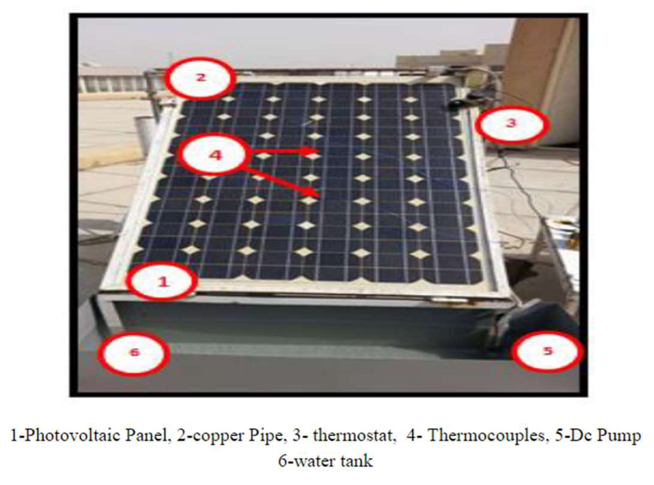
Figure 2.
Schematic illustration a PV/T system.
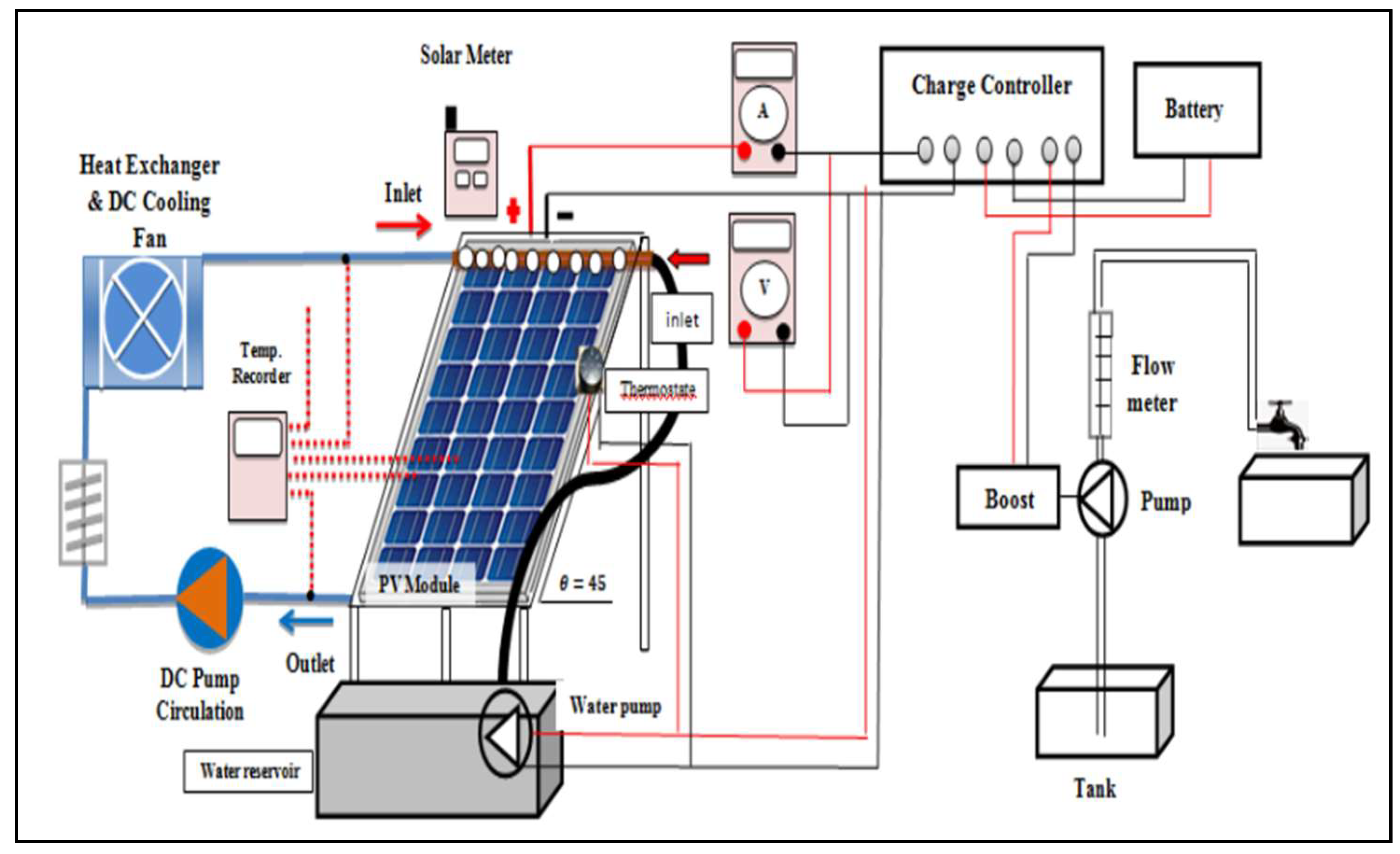
Figure 3.
Design of a copper pipe in an elliptical shape.
Figure 4.
Schematic illustration of the experimental setup.
Figure 5.
The actual experimental setup.
Figure 6.
Schematic diagram of the setup.
Figure 7.
Front cross-section view of the PV/T panel.
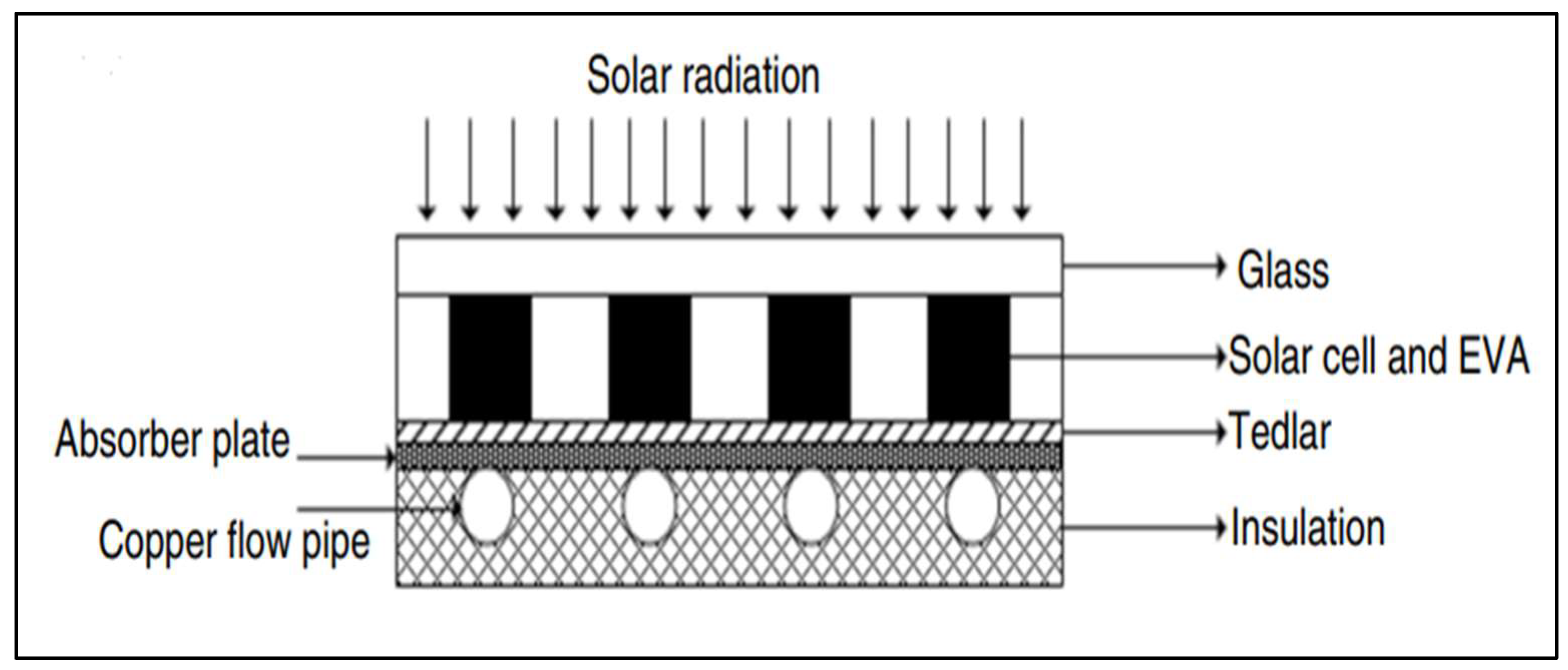
Figure 8.
Schematic diagram of the experiment.
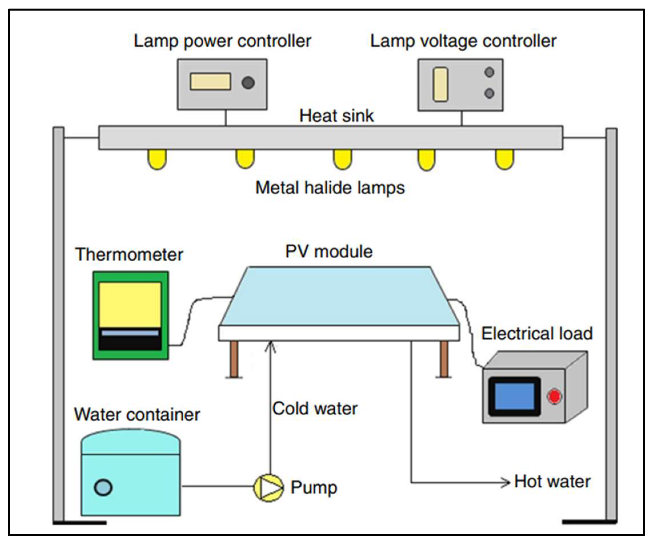
Figure 9.
Dimensions of the PV panel and the placements of the thermocouples.
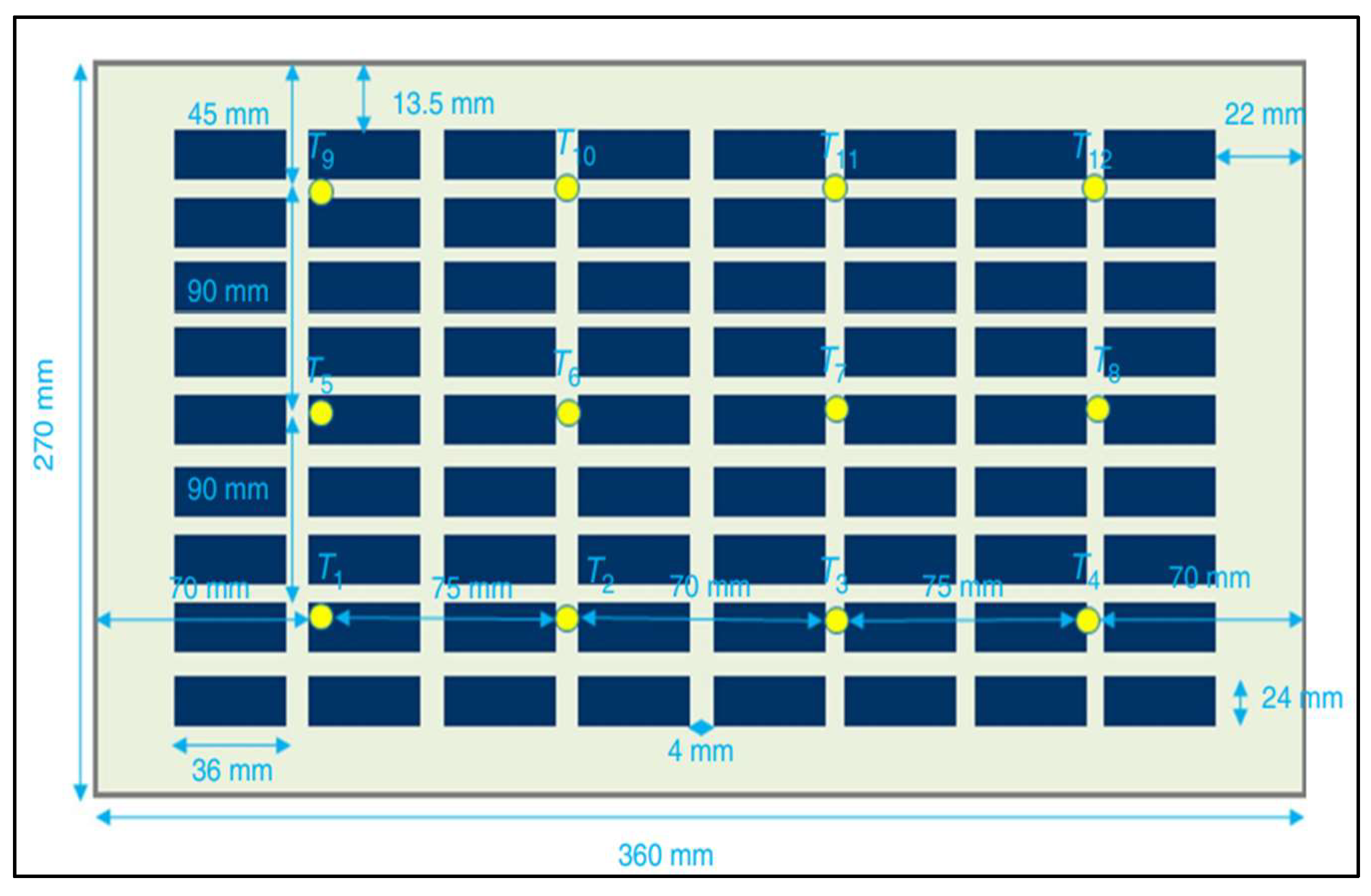
Figure 10.
Integrated TEC Thermocouples apparatus.
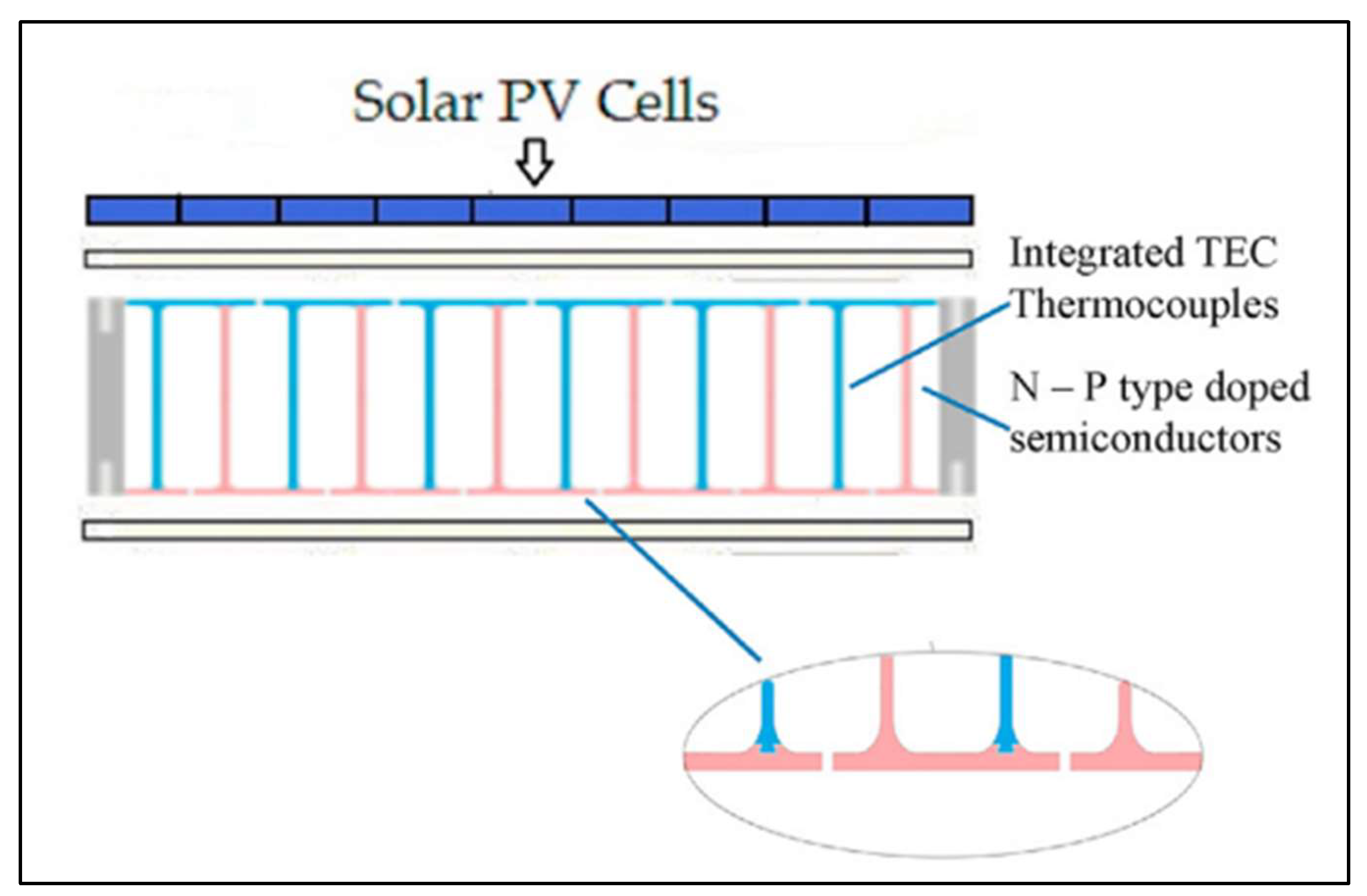
Figure 11.
(a) Required space is set up for the study; (b) the heat exchanger used in this study; (c) the distribution of thermocouple on the Underground Heat Exchanger.
Figure 11.
(a) Required space is set up for the study; (b) the heat exchanger used in this study; (c) the distribution of thermocouple on the Underground Heat Exchanger.
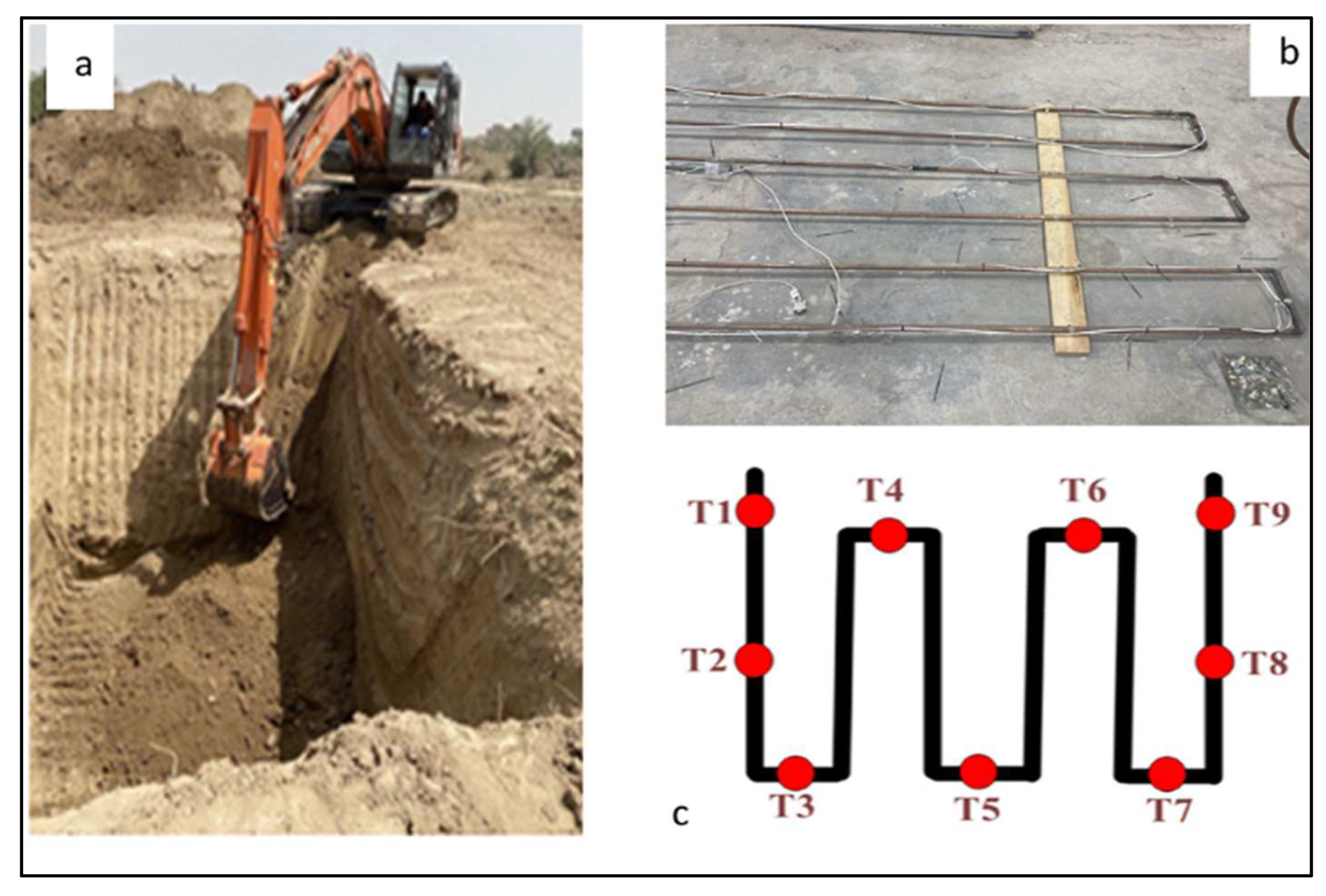
Figure 12.
The fluid dynamics within the pipeline.
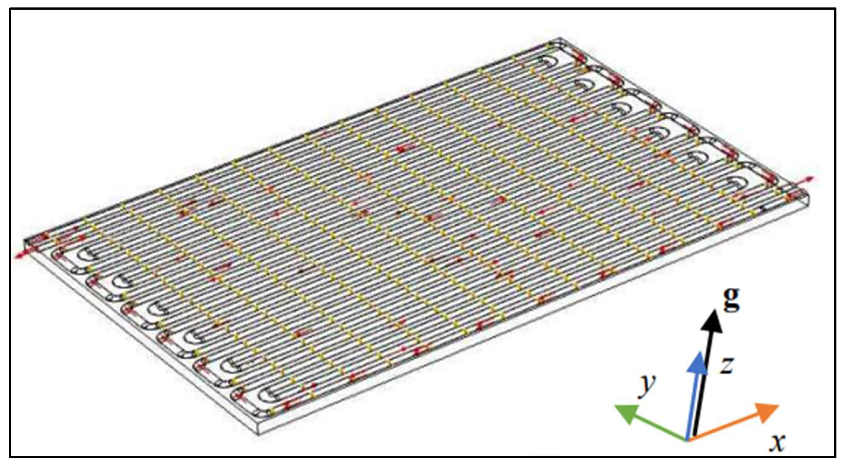
Figure 13.
Layers for the solar module with a minichannel heat sink.
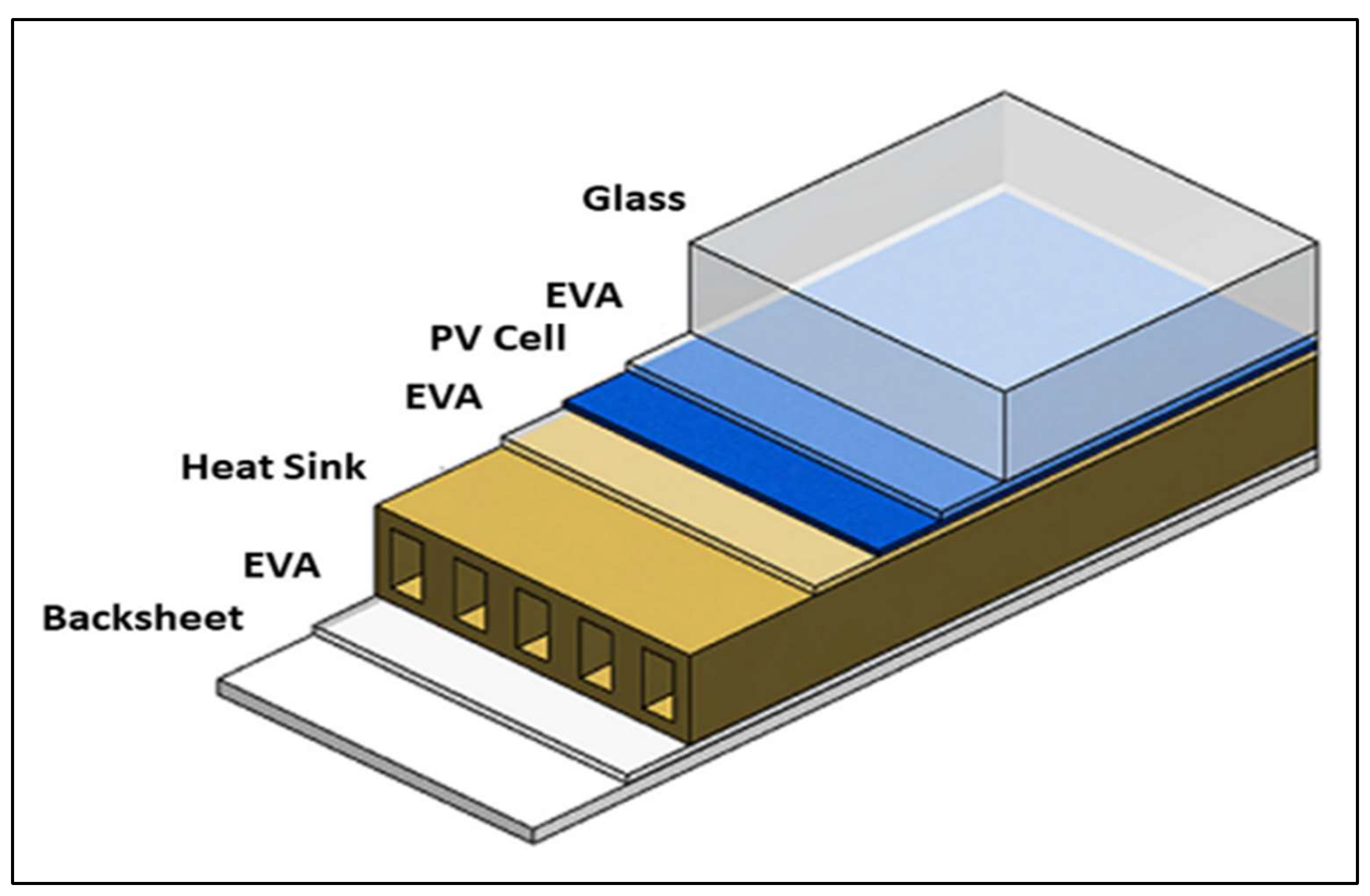
Figure 14.
Schematic representation of the PV panel with the cooling system.
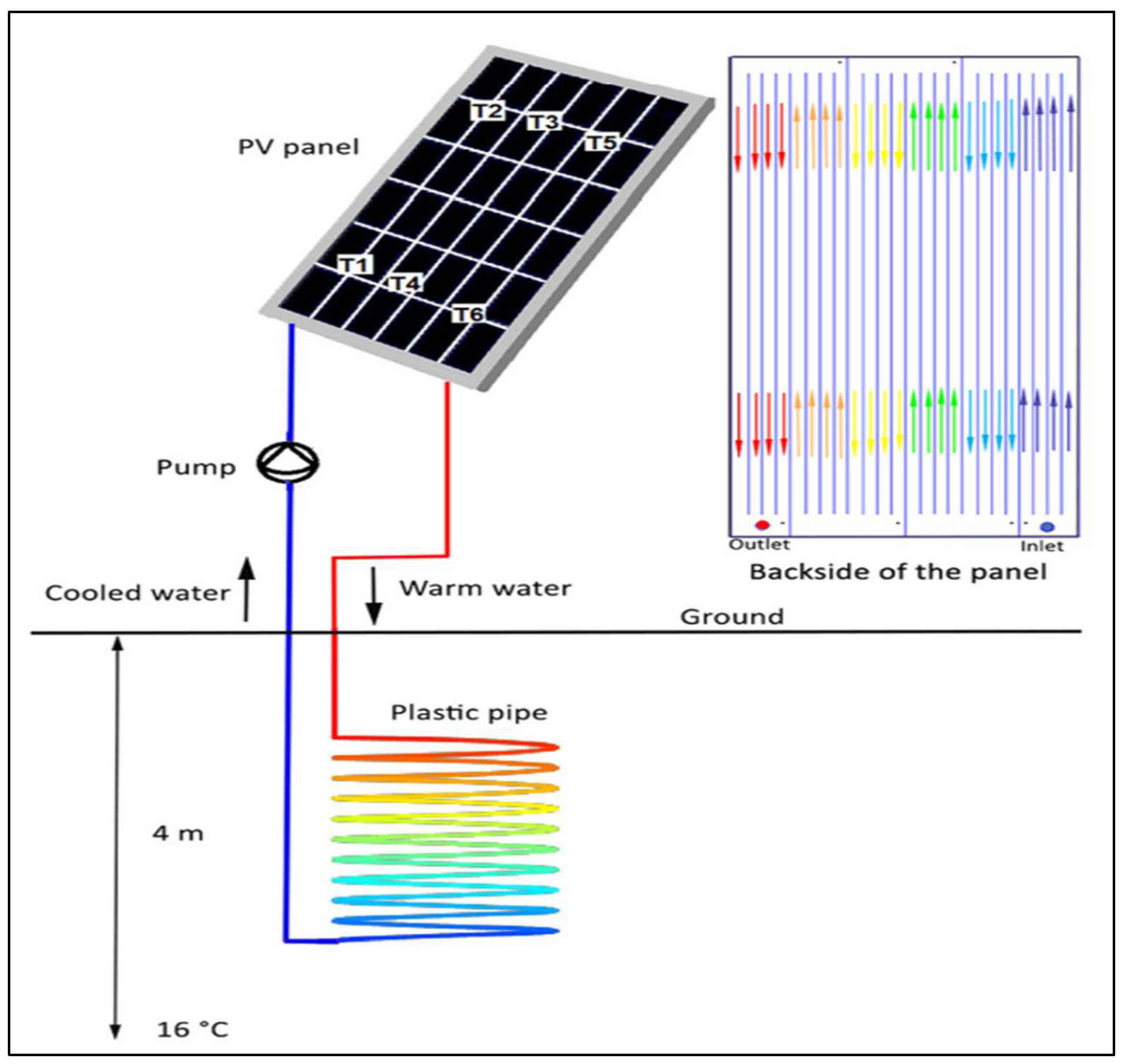
Figure 15.
Numerical simulation of the solar panel using the TRNSYS software.
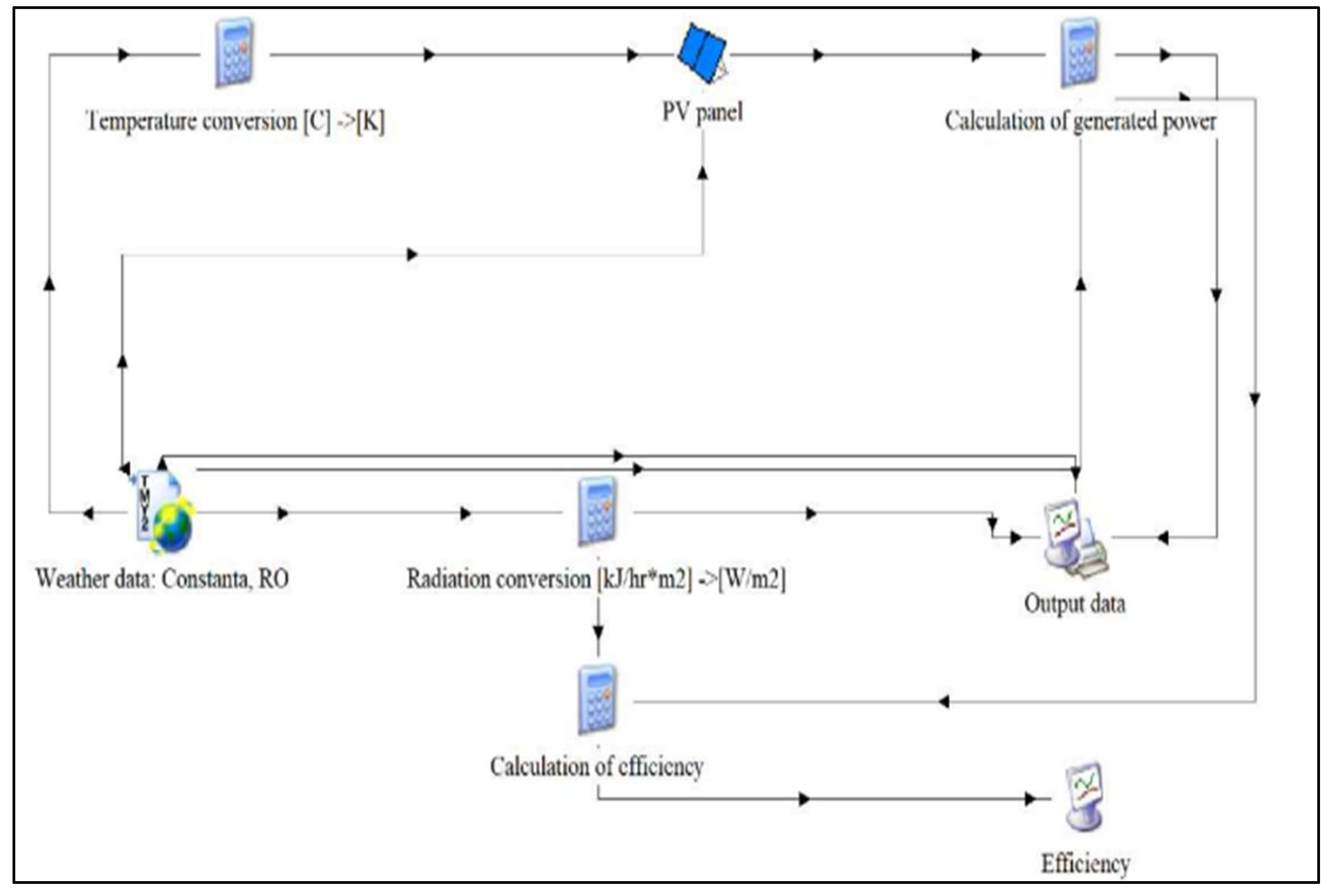
Figure 16.
Schematics of chosen designs for optimization, utilizing design 1 as the baseline.
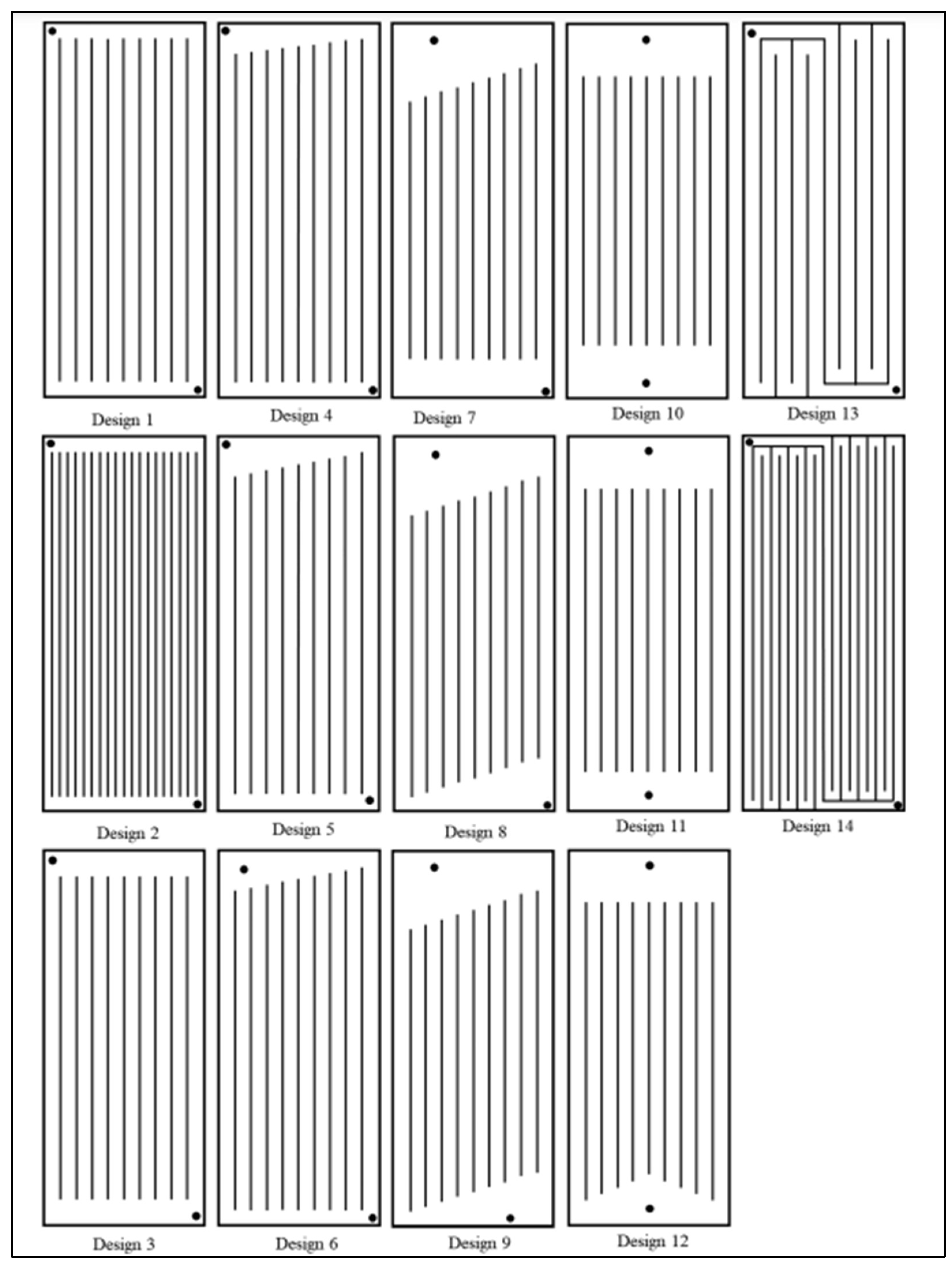
Figure 17.
Procedure to prepare nanofluid.
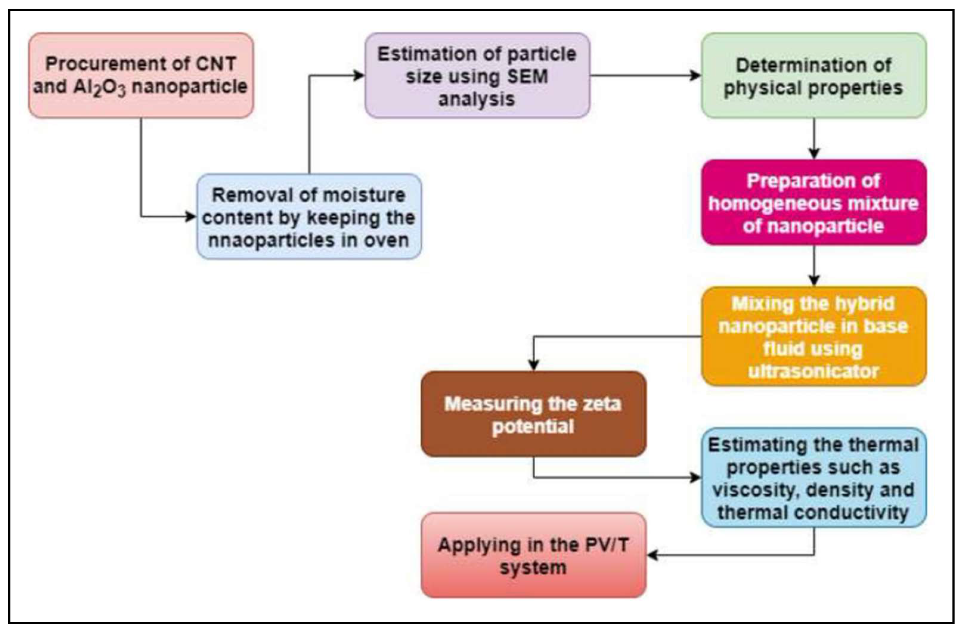
Figure 18.
Experiment setup of stand alone PV panel without cooling.
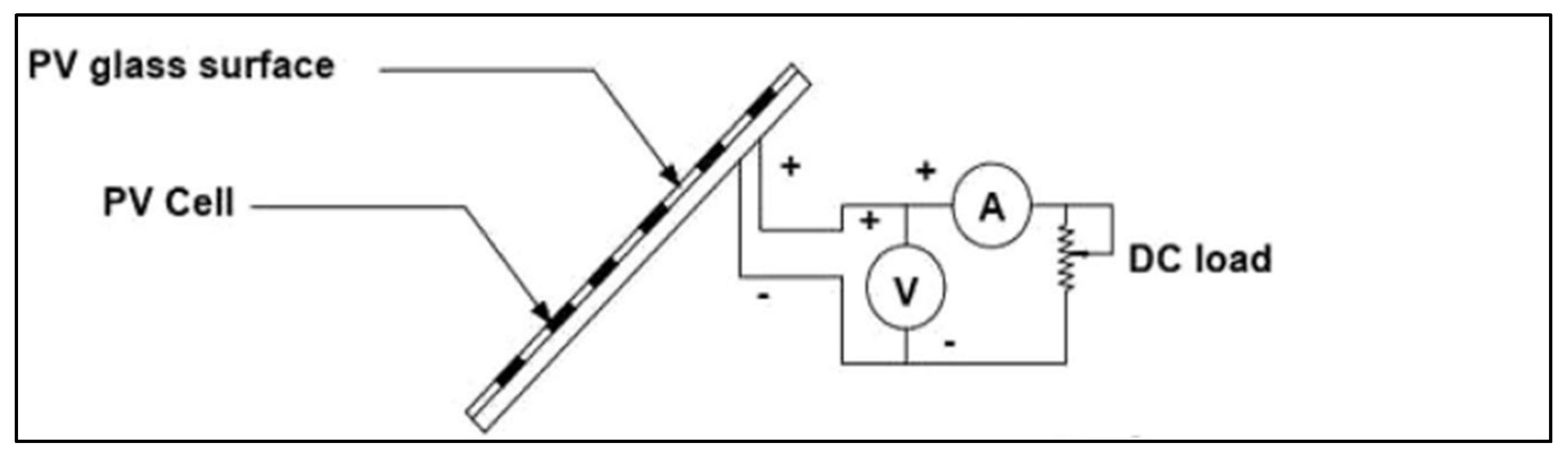
Figure 19.
PV/T system with cooling system.
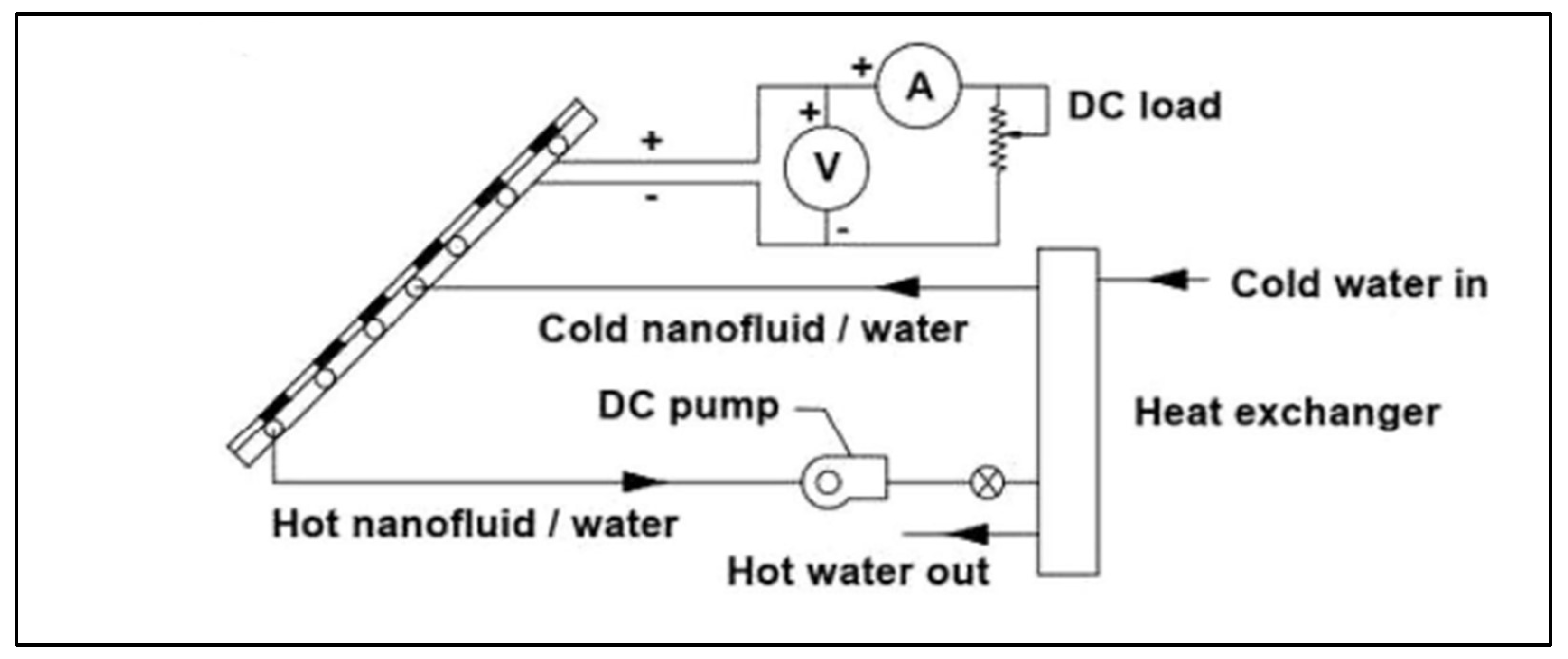
Figure 20.
Schematic diagram of the cooling setup where T1, T2, and T3 are thermocouple. The red path symbolizes the thermal circuit, whereas the blue path represents the electric circuit.
Figure 20.
Schematic diagram of the cooling setup where T1, T2, and T3 are thermocouple. The red path symbolizes the thermal circuit, whereas the blue path represents the electric circuit.
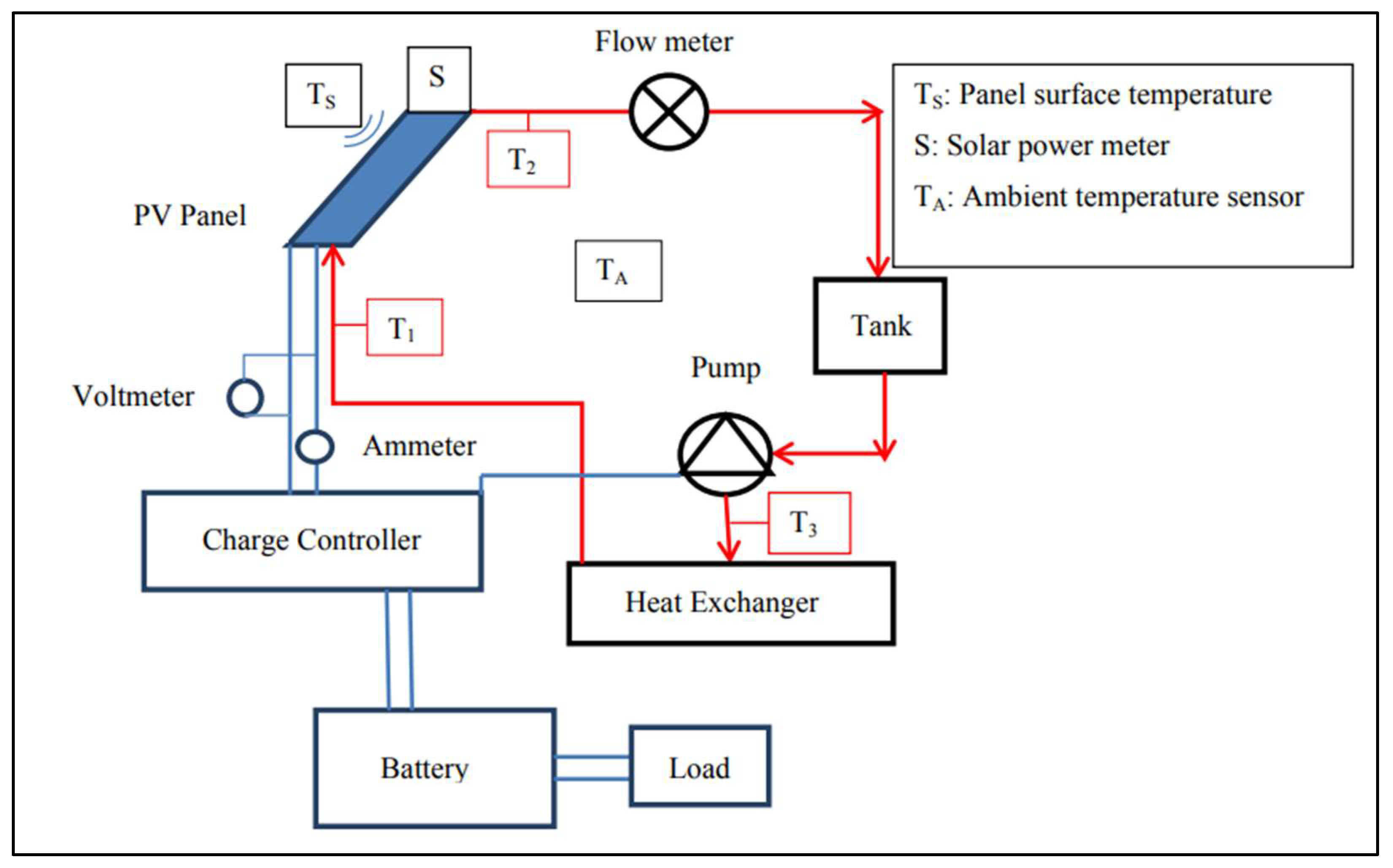
Figure 21.
(a) PV panel model in Comsol software, (b) Serpentine back pipes, and (c) Square back pipes.
Figure 21.
(a) PV panel model in Comsol software, (b) Serpentine back pipes, and (c) Square back pipes.
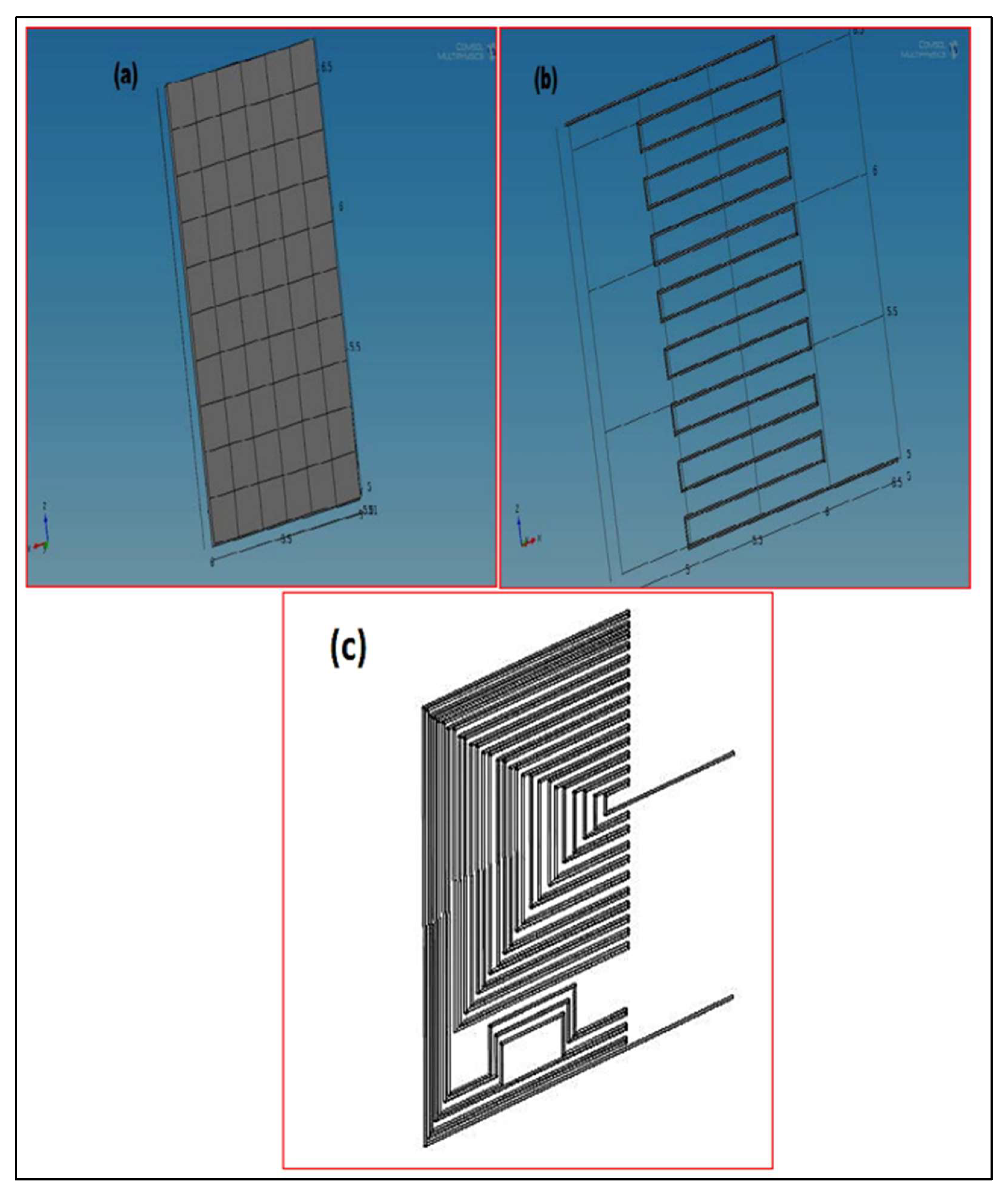
Figure 22.
Combination of PVT with TEG.
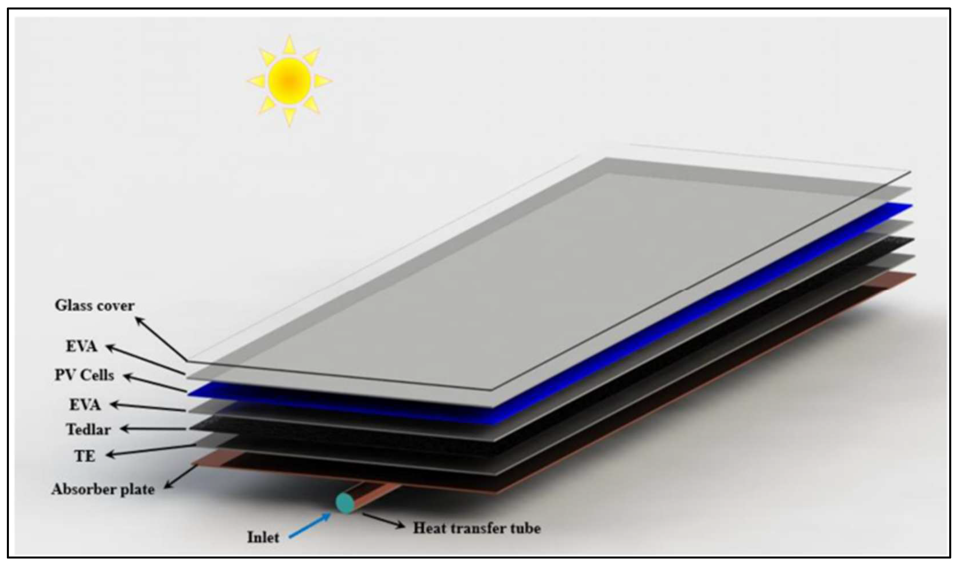
Figure 23.
The proposed designs for the cooling duct cross-section.
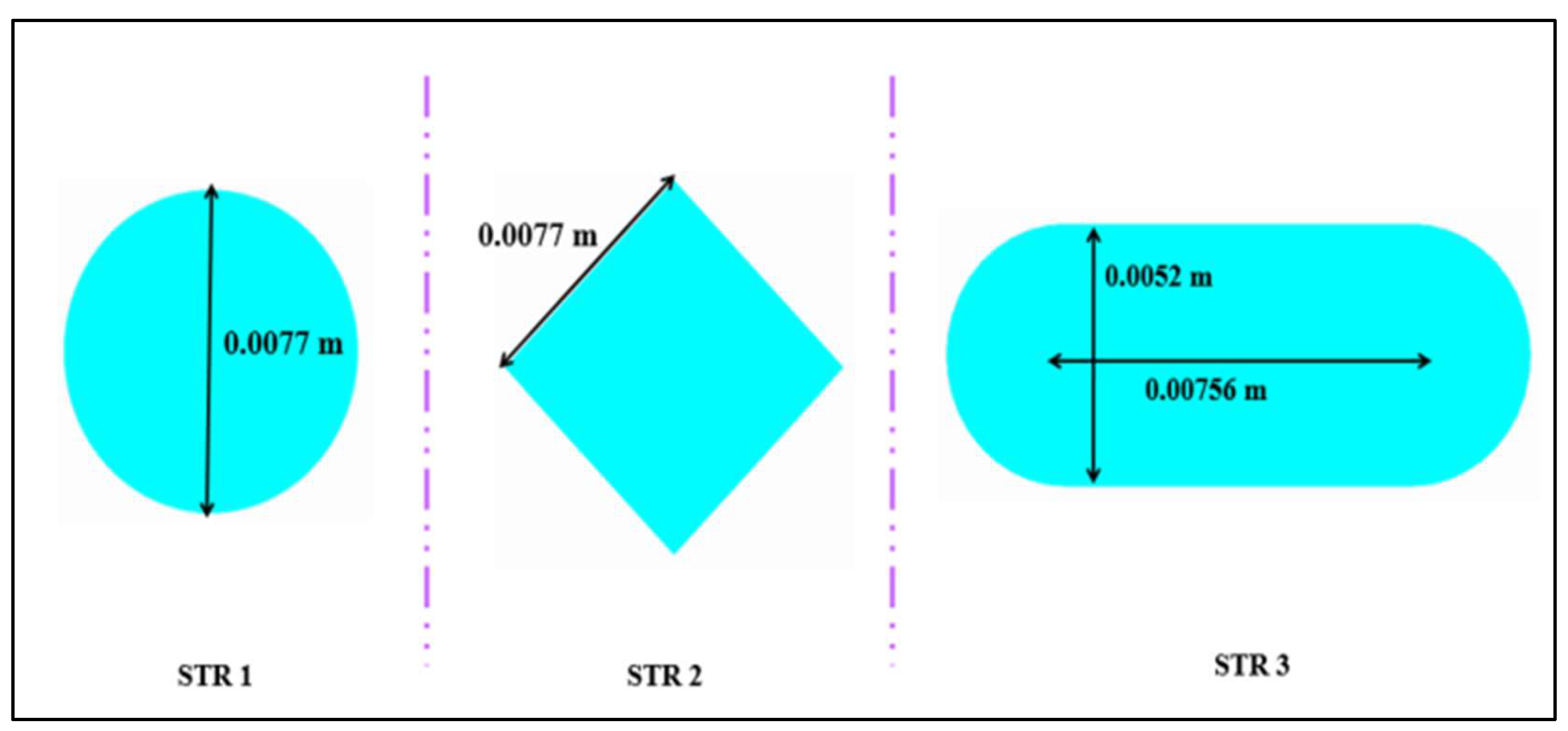
Figure 24.
Representation of the actual model.
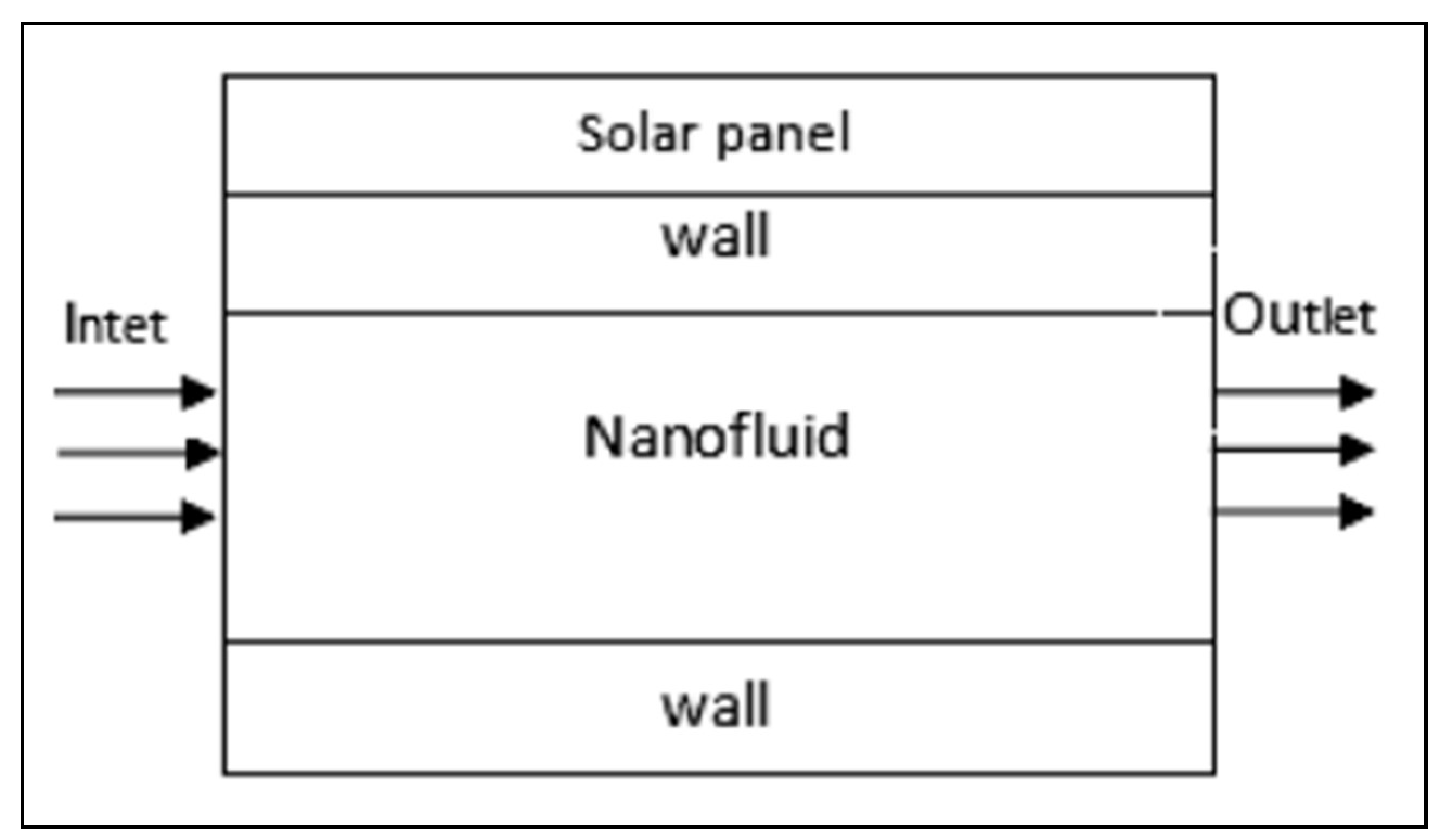
Figure 25.
Arrangement of rig.
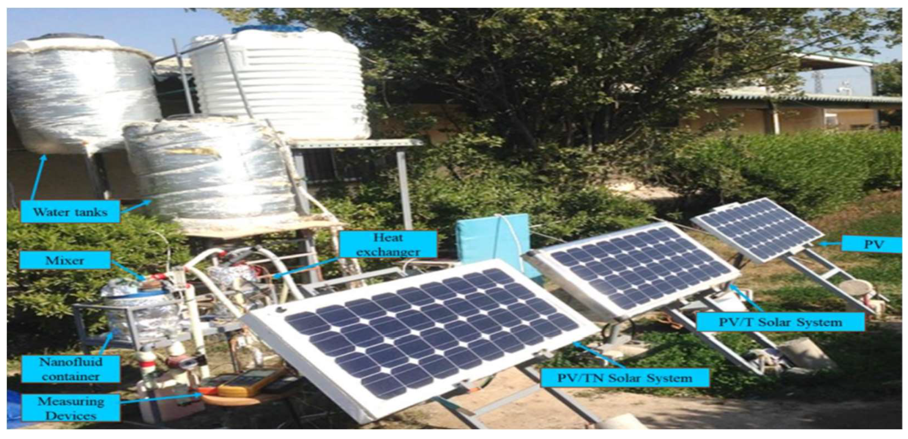
Figure 26.
Diagram of the photovoltaic/thermal nanofluid system.
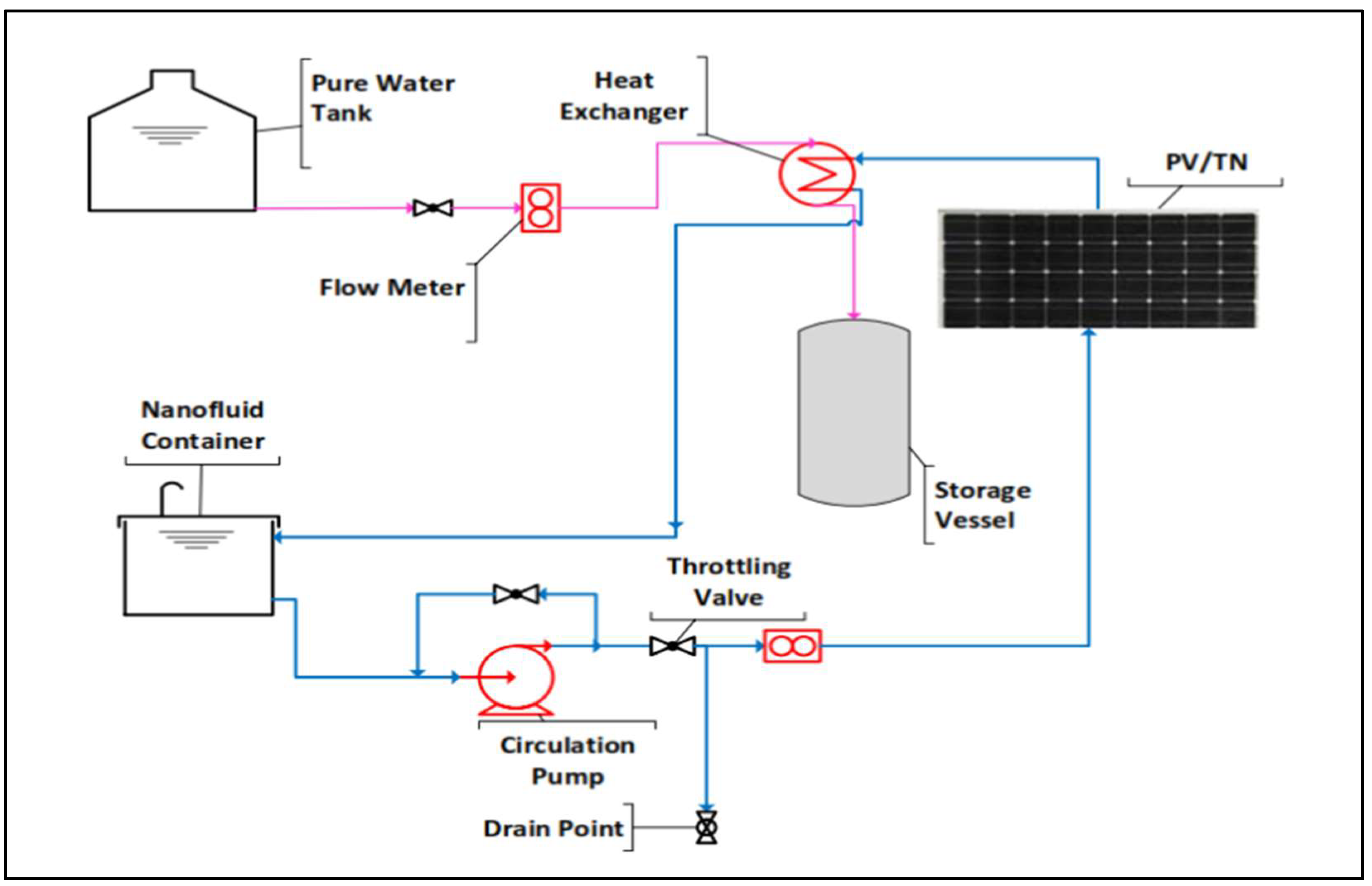
Figure 27.
Diagram of the photovoltaic/thermal system.
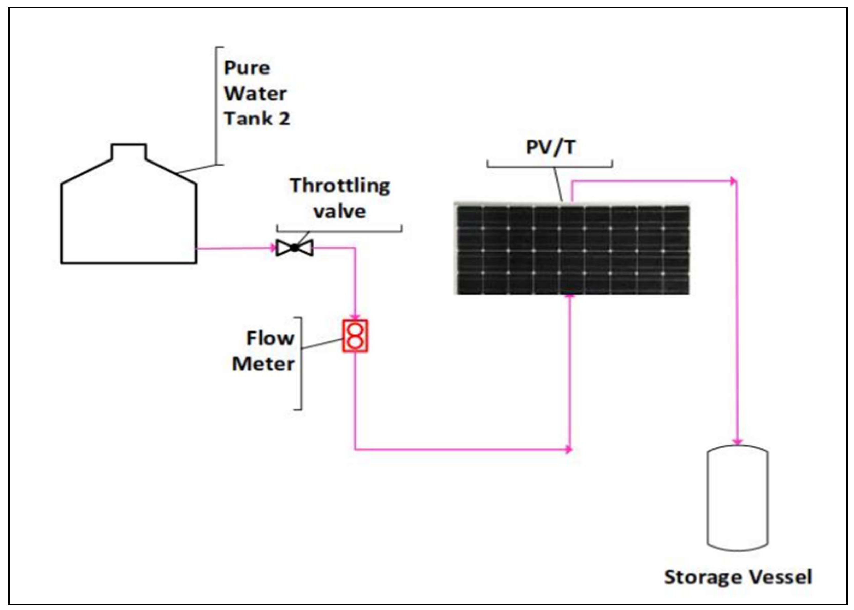
Figure 28.
An aluminium rectangular heat exchanger is currently being fabricated.
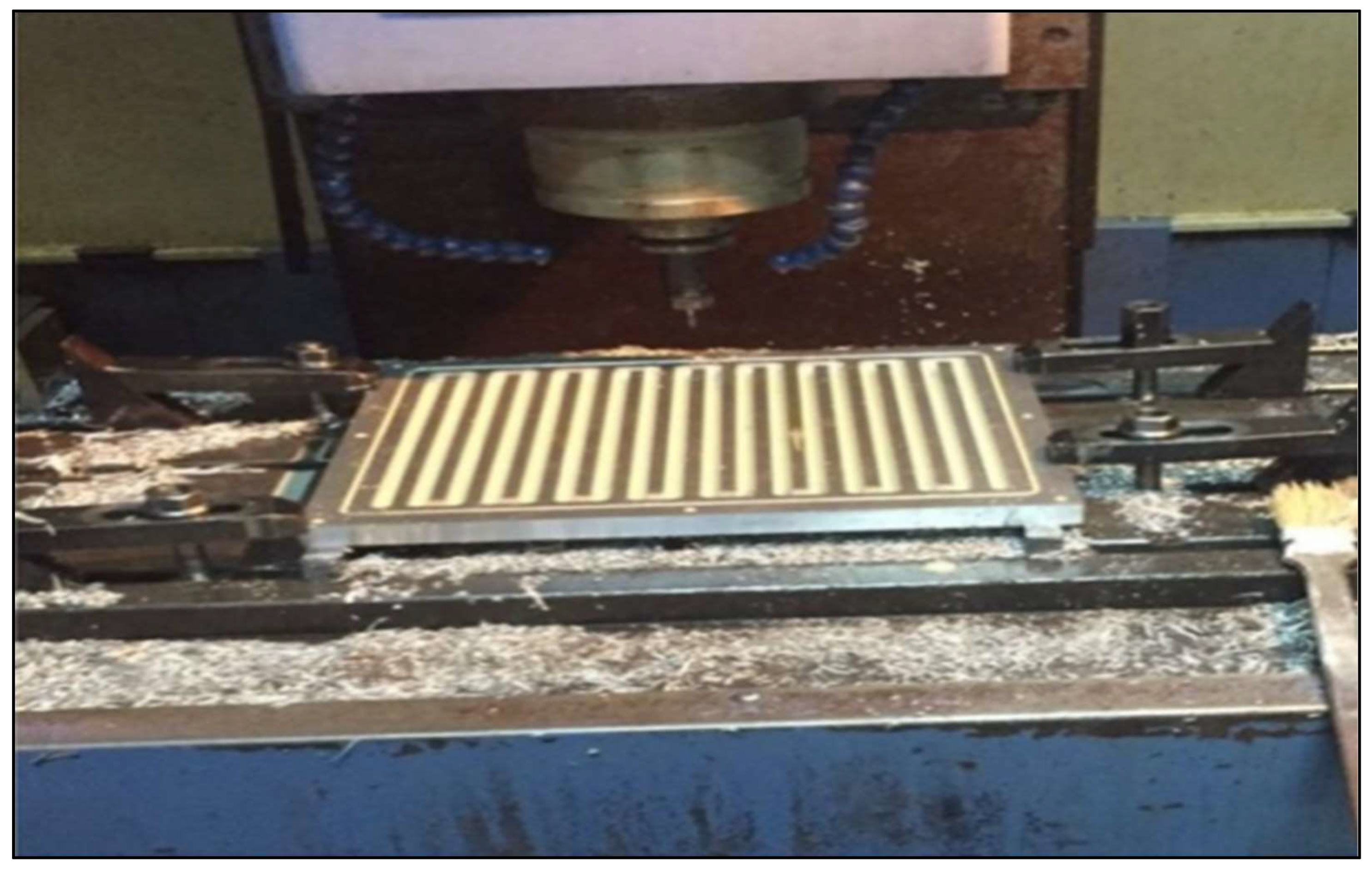
Figure 29.
Current experimental configuration.
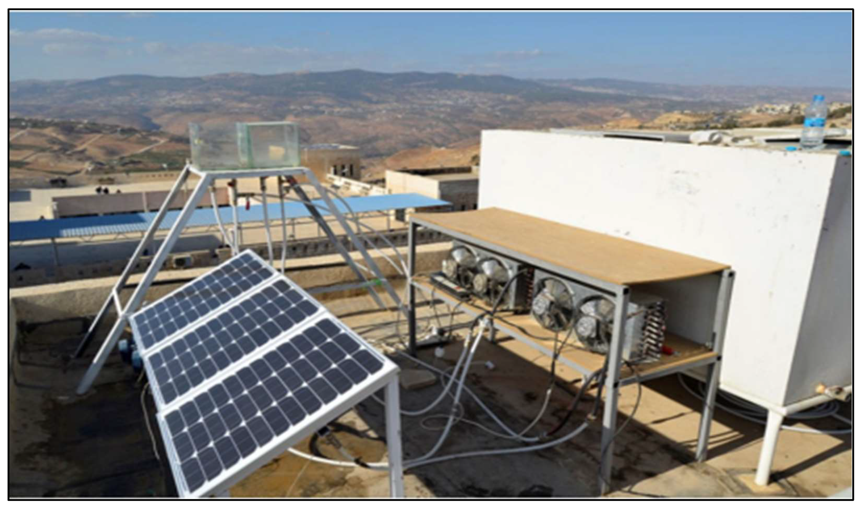
Figure 30.
Diagram depicting the experimental setup.
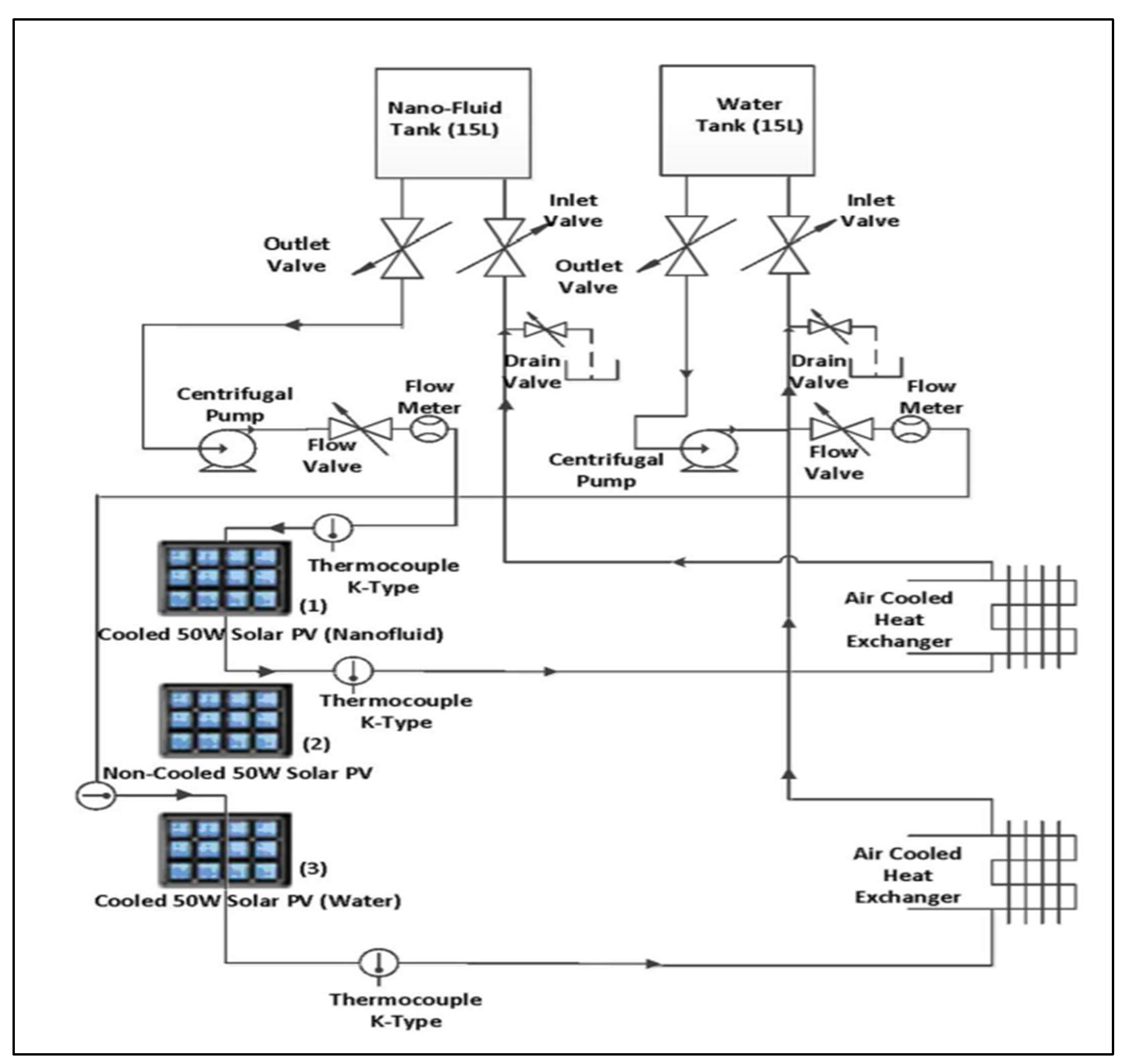
Figure 31.
A diagram illustrating the layout of components for constructing the experimental PV/T configuration.
Figure 31.
A diagram illustrating the layout of components for constructing the experimental PV/T configuration.
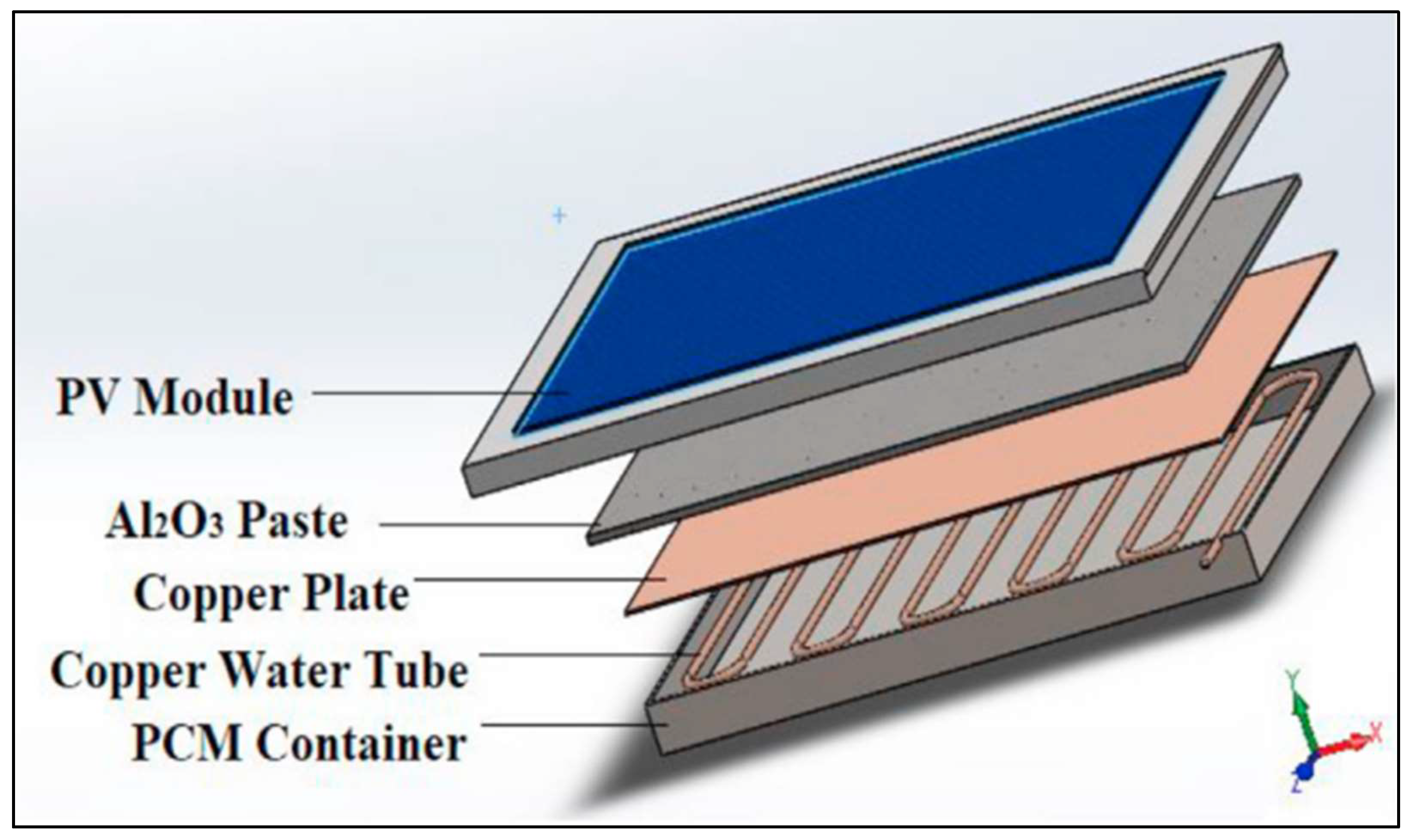
Figure 32.
(a) PCM container filled with melted salt hydrate (b) The actual experiment setup.
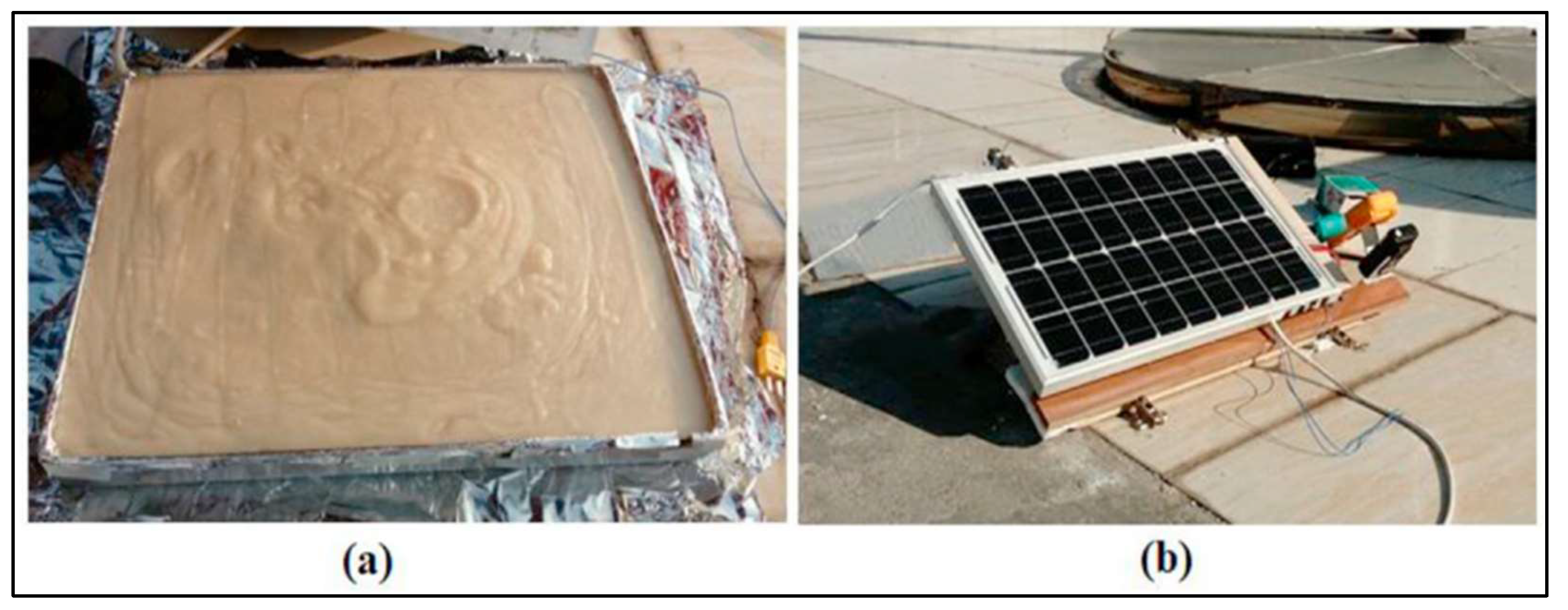
Figure 33.
The circuit developed to calculate the maximum power generated by photovoltaic panels at each time interval.
Figure 33.
The circuit developed to calculate the maximum power generated by photovoltaic panels at each time interval.
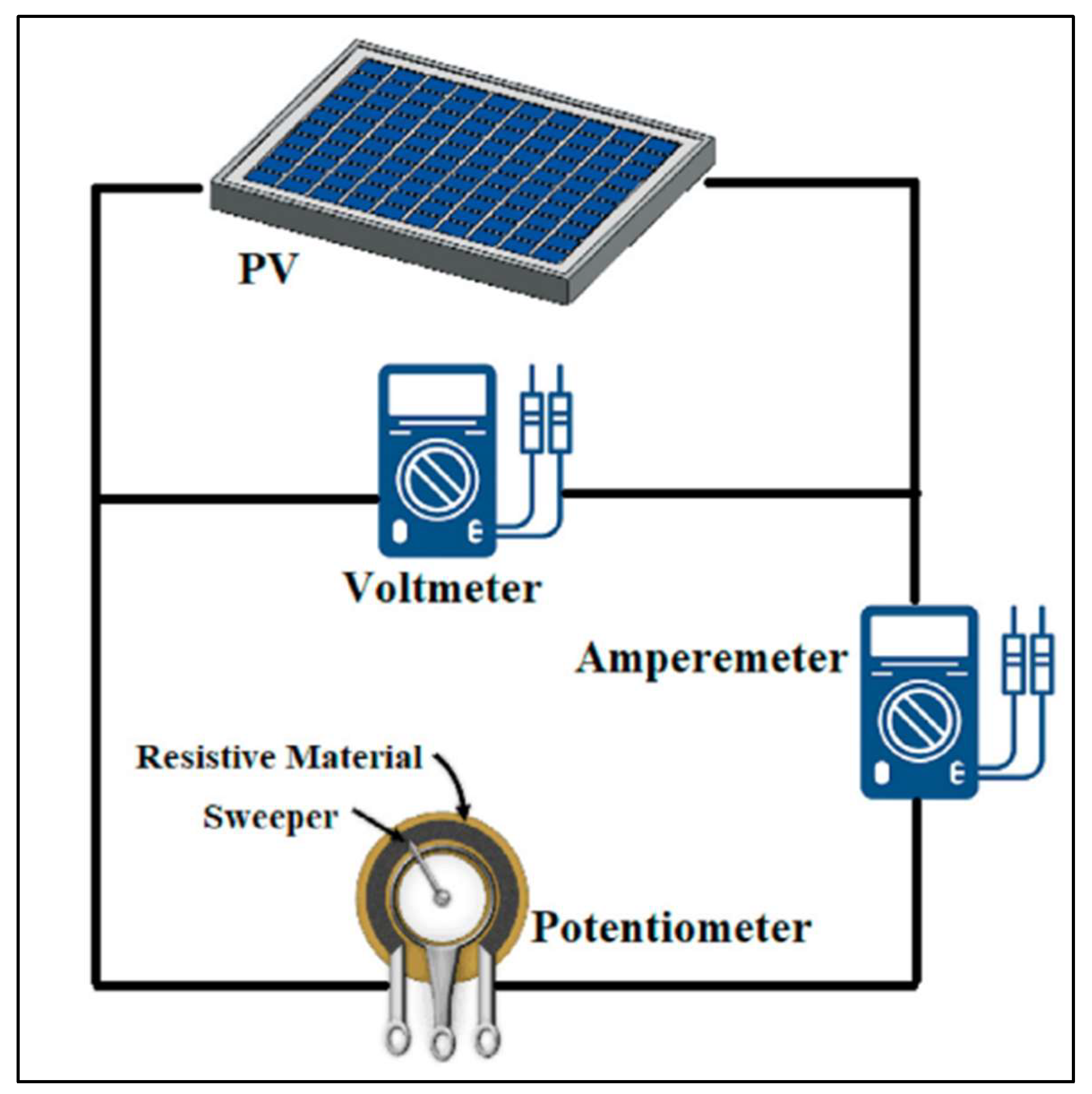
Figure 34.
The schematic diagram of the experimental setup.
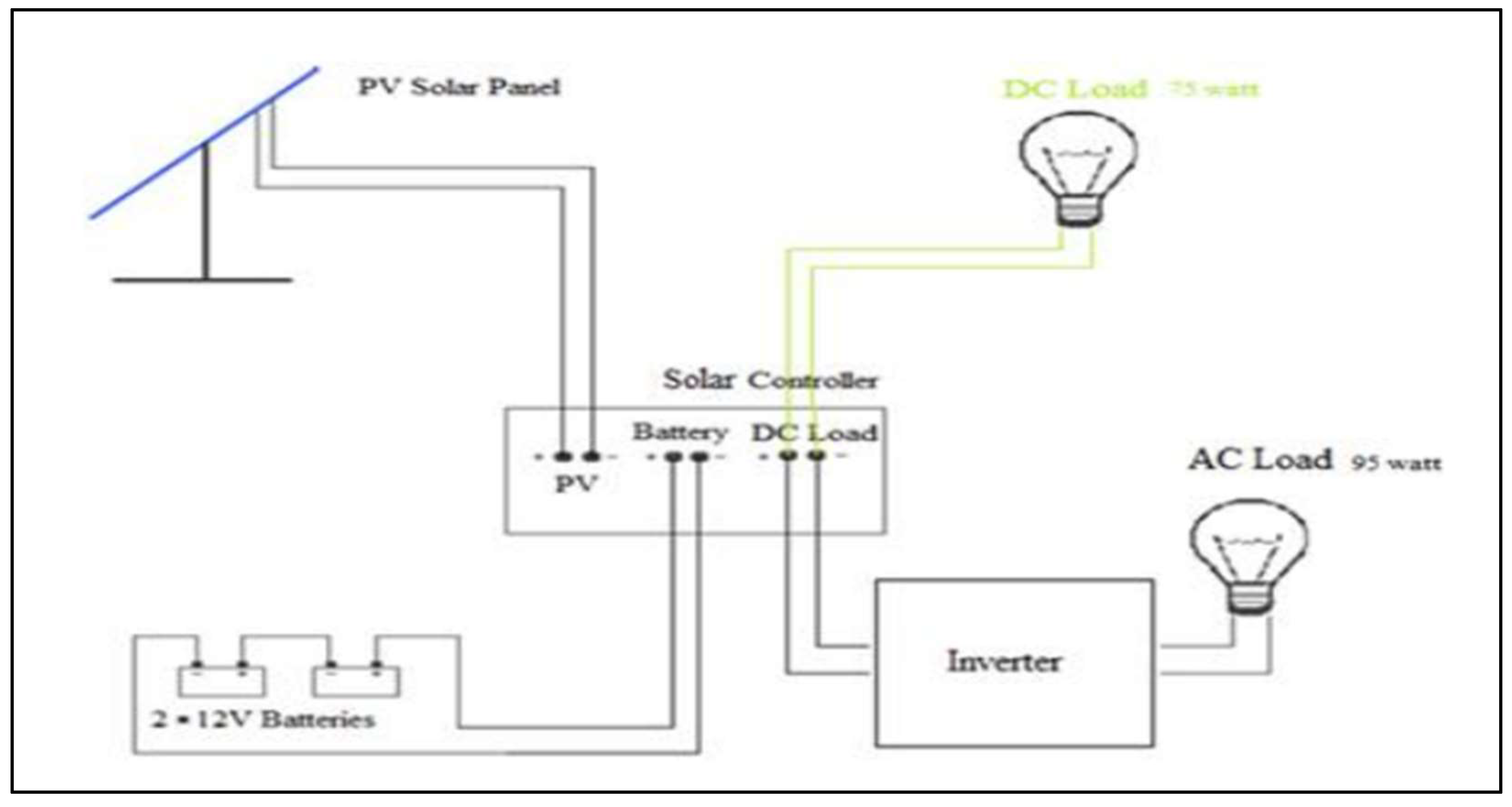
Figure 35.
The representation of heat flux of PV combined PCM unit.
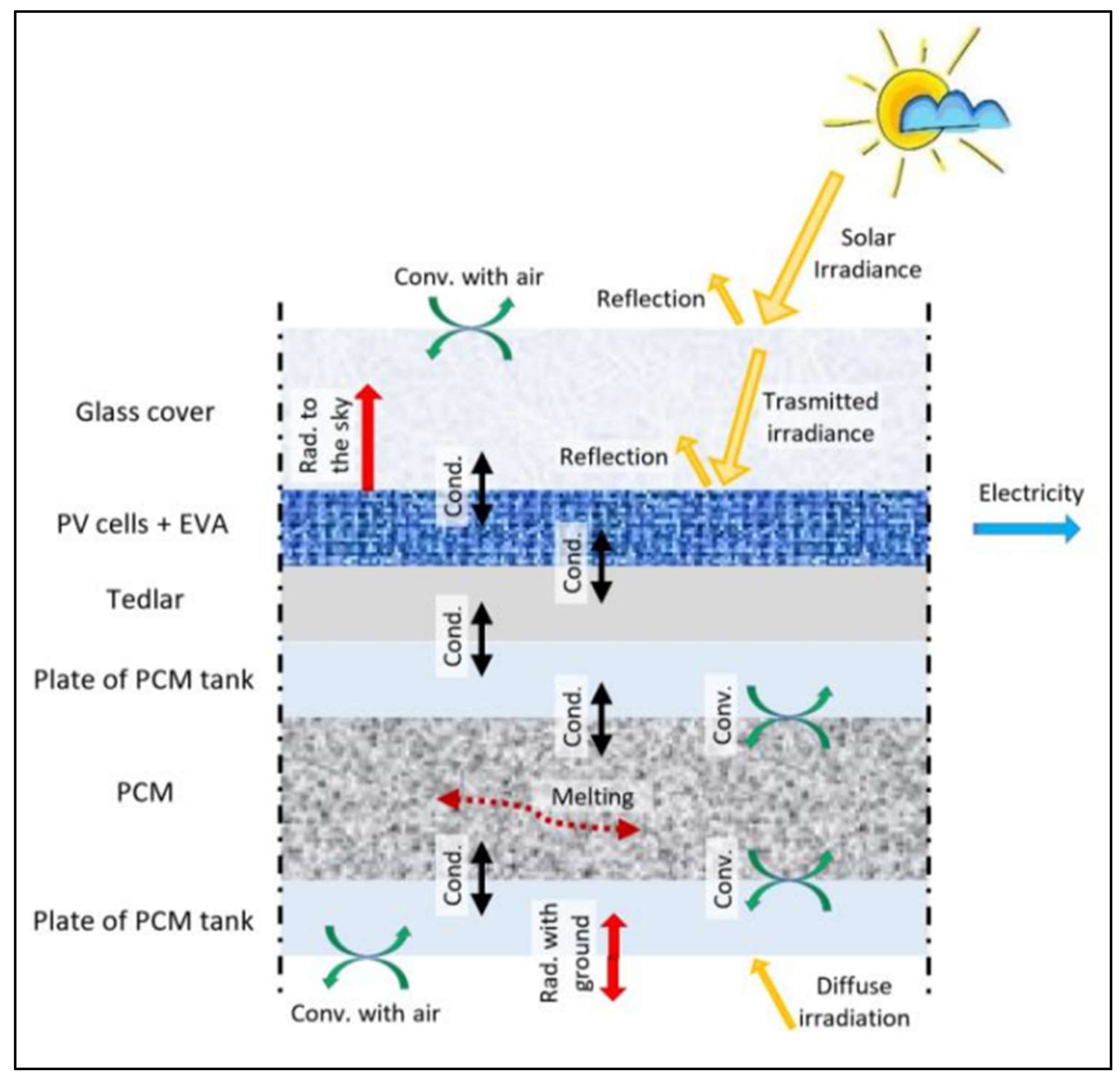
Figure 36.
REEEC operates solar systems with an overall capacity of 9 kilowatts. Electrical characteristics are provided under standard test conditions (STC) with an irradiation of 1000W/m2, a range of 1.5 air mass, and a cell temperature of 25˚C.
Figure 36.
REEEC operates solar systems with an overall capacity of 9 kilowatts. Electrical characteristics are provided under standard test conditions (STC) with an irradiation of 1000W/m2, a range of 1.5 air mass, and a cell temperature of 25˚C.
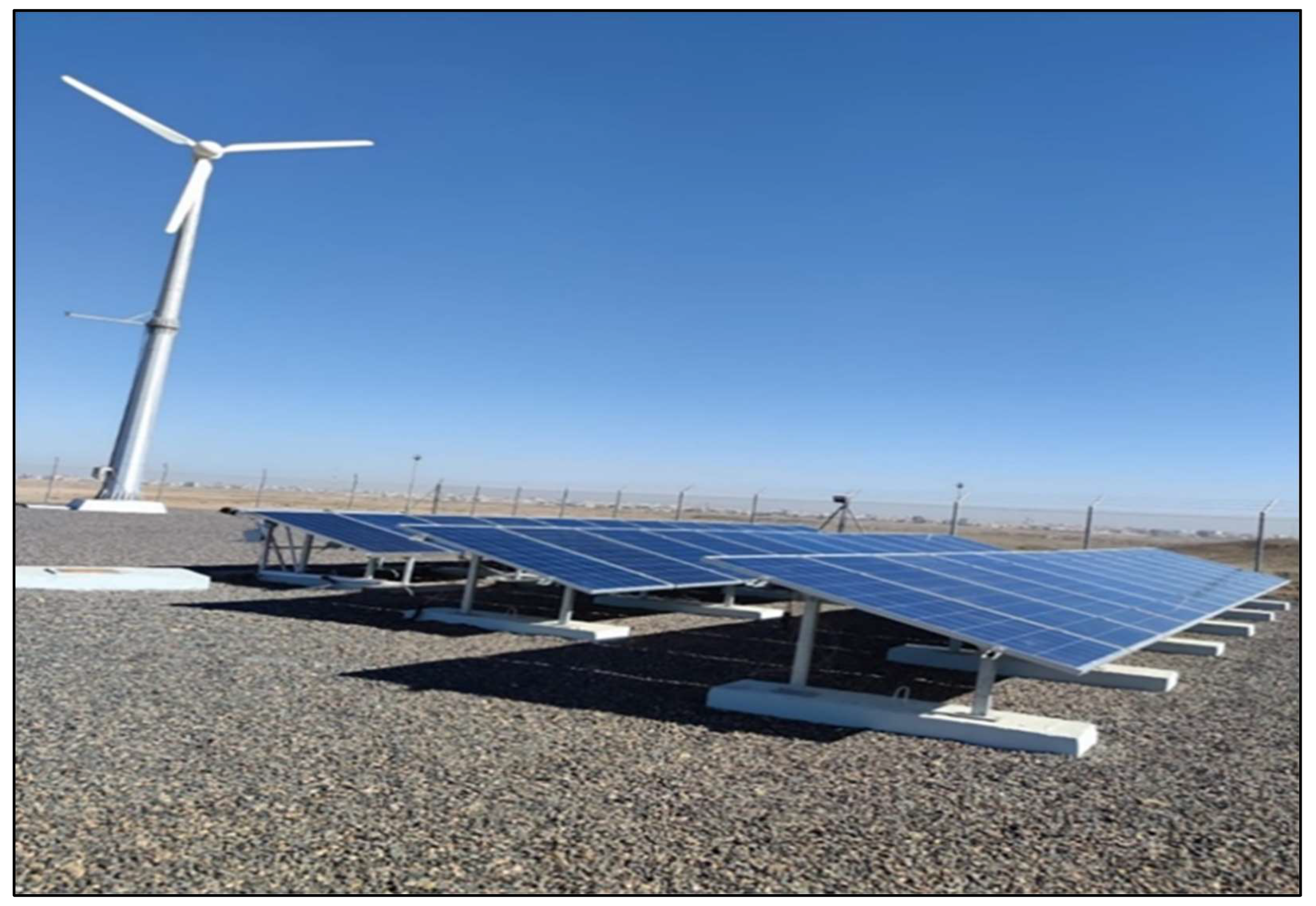
Figure 37.
a) PCM packs filled with PCM-OM37P substance b) Positioning of the front and rear thermocouples.
Figure 37.
a) PCM packs filled with PCM-OM37P substance b) Positioning of the front and rear thermocouples.
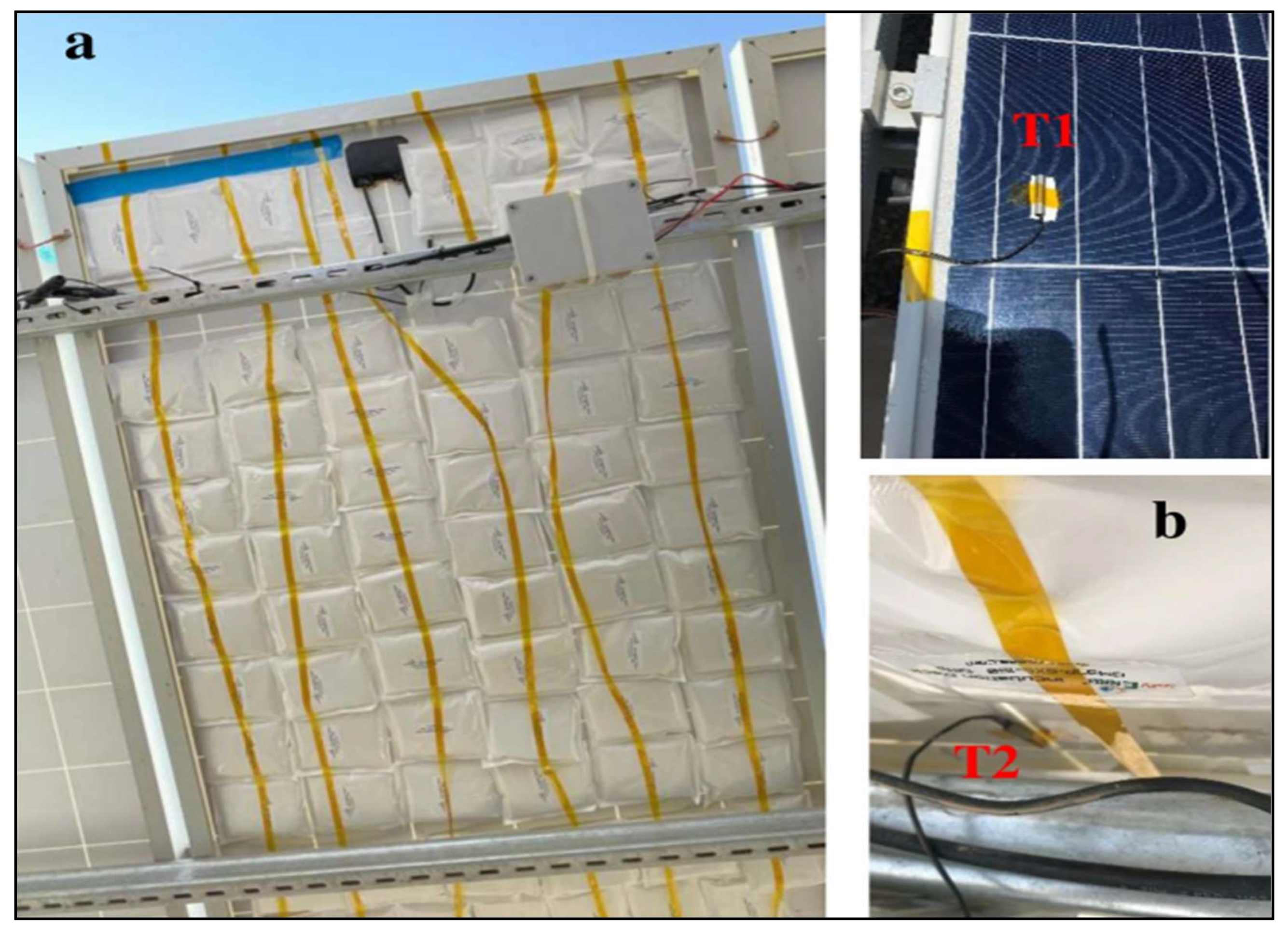
Figure 38.
The diagram shows the experimental setup and the PV/TEG configuration.

Figure 39.
The image of the experimental arrangement.
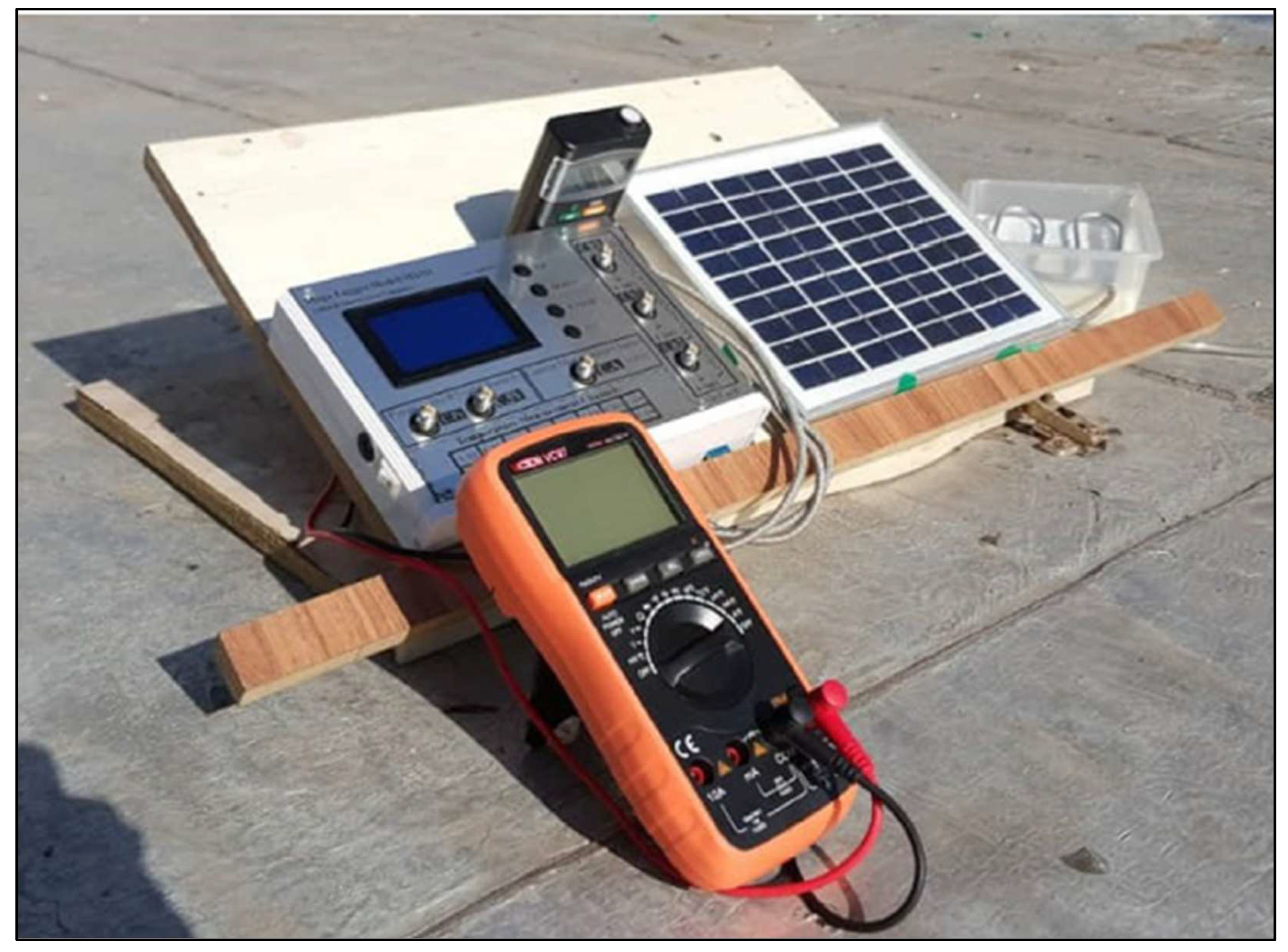
Figure 40.
Rear view of photovoltaic systems: PV + PCM on the left, PV + fin3 on the top right, and reference PV on the bottom right. The systems are located at 36° and 42° North latitudes.
Figure 40.
Rear view of photovoltaic systems: PV + PCM on the left, PV + fin3 on the top right, and reference PV on the bottom right. The systems are located at 36° and 42° North latitudes.
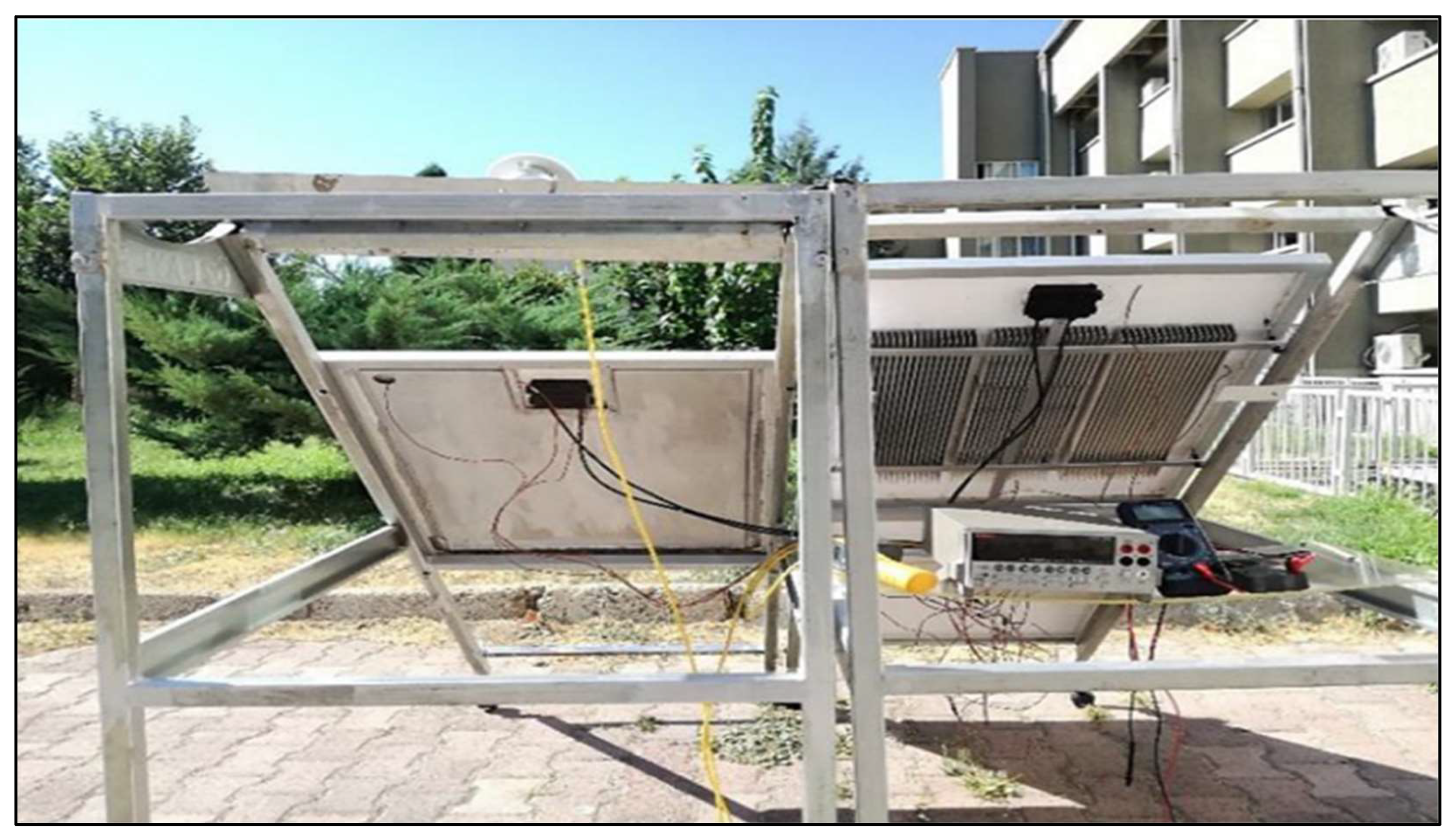
Figure 43.
Front and rear perspectives of the experimental configuration.
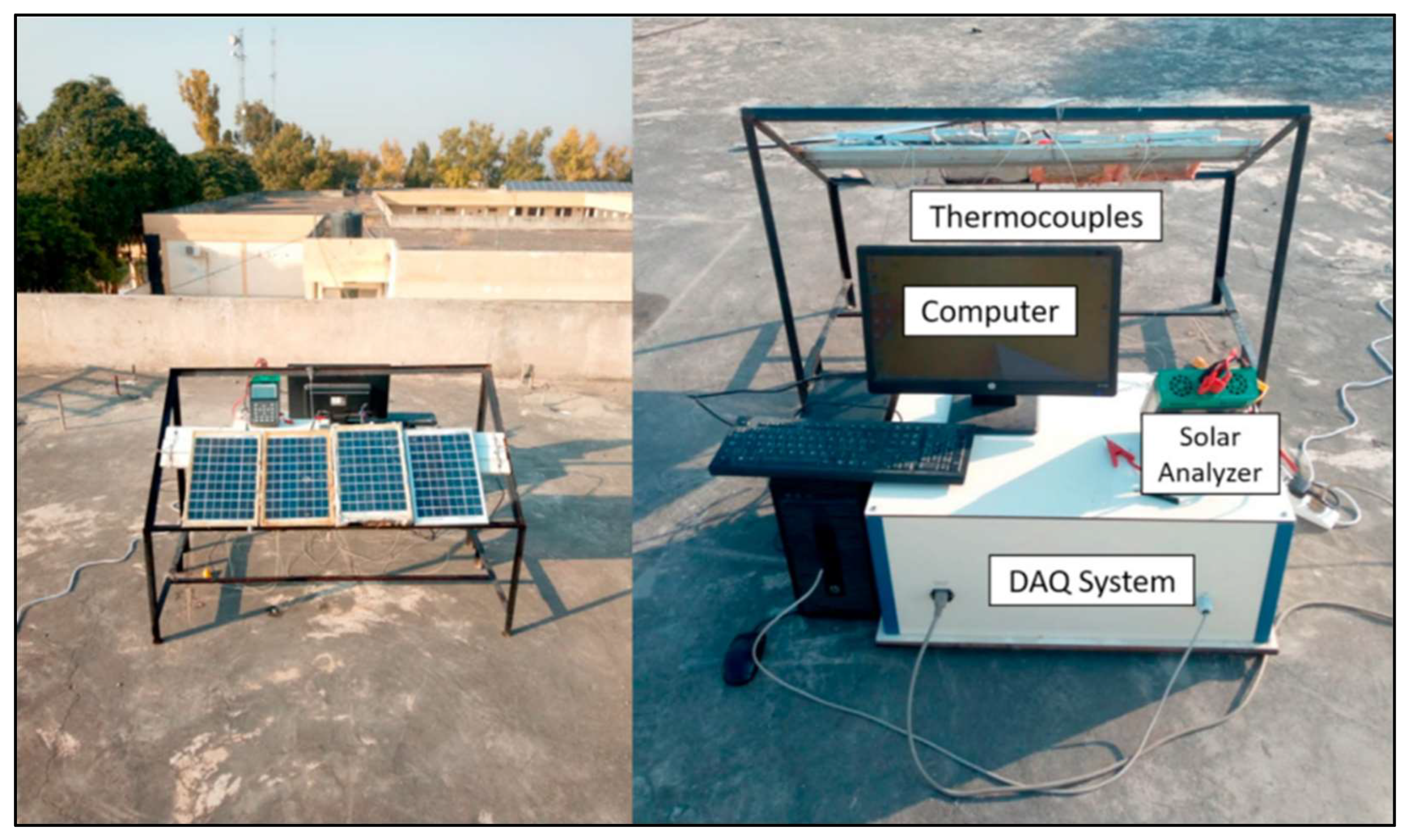
Figure 44.
Diagram illustrating the Experimental Setup.
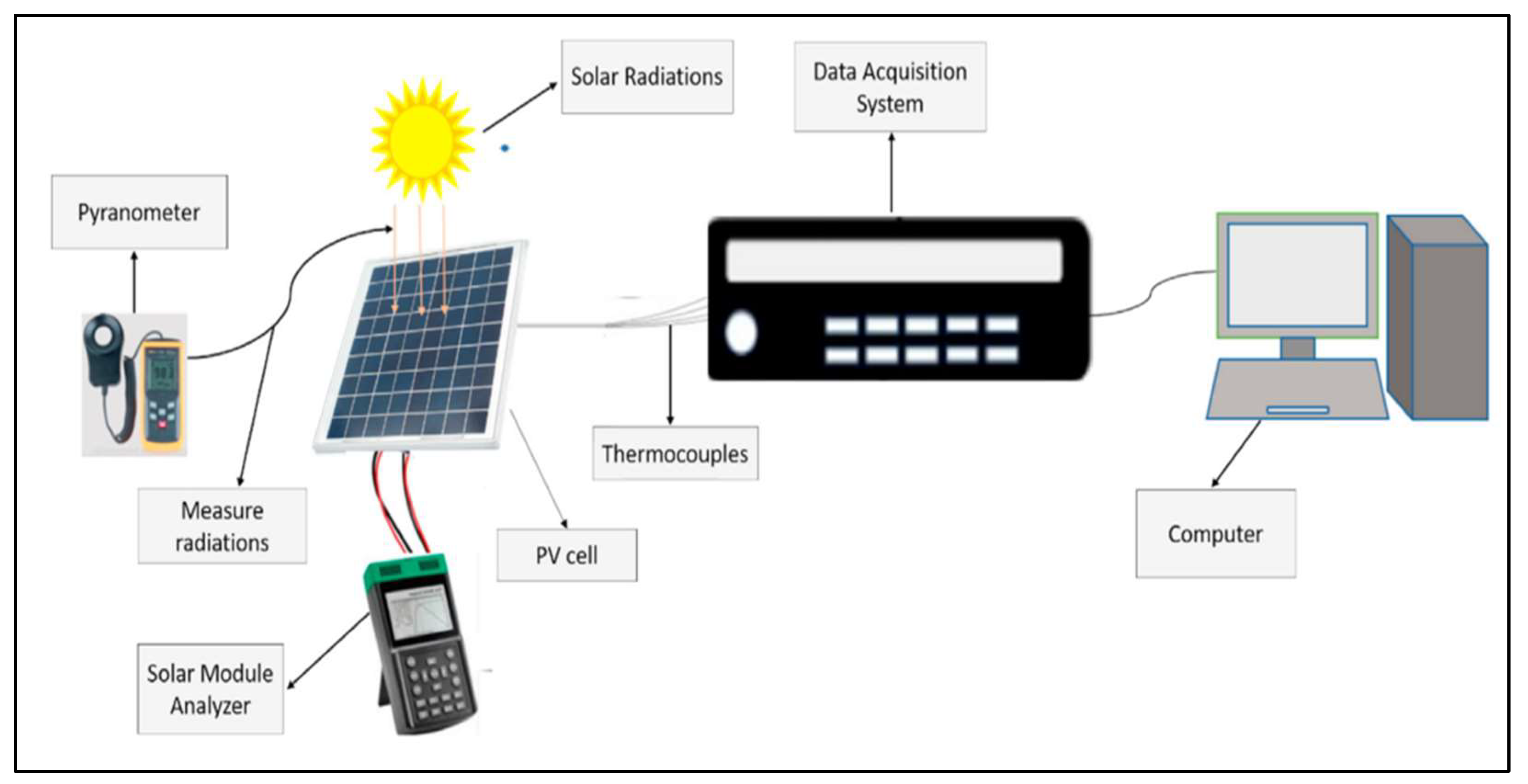
Figure 45.
a) System setup b) heat exchange path.
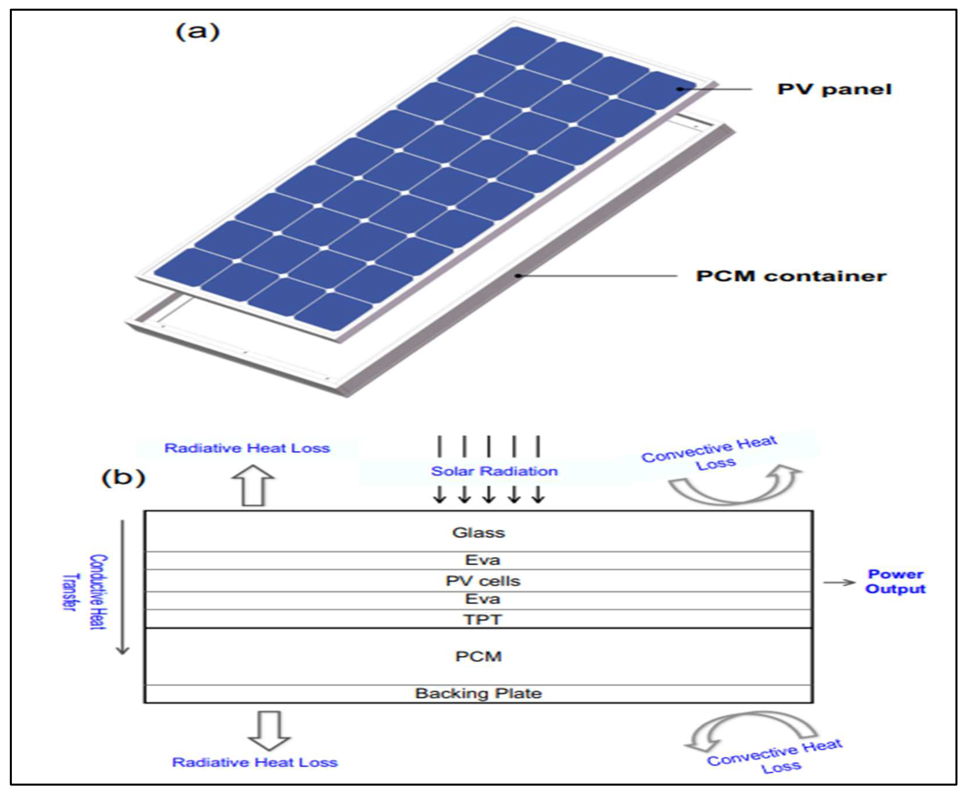
Figure 46.
Layout of PV-PCM system experiment.
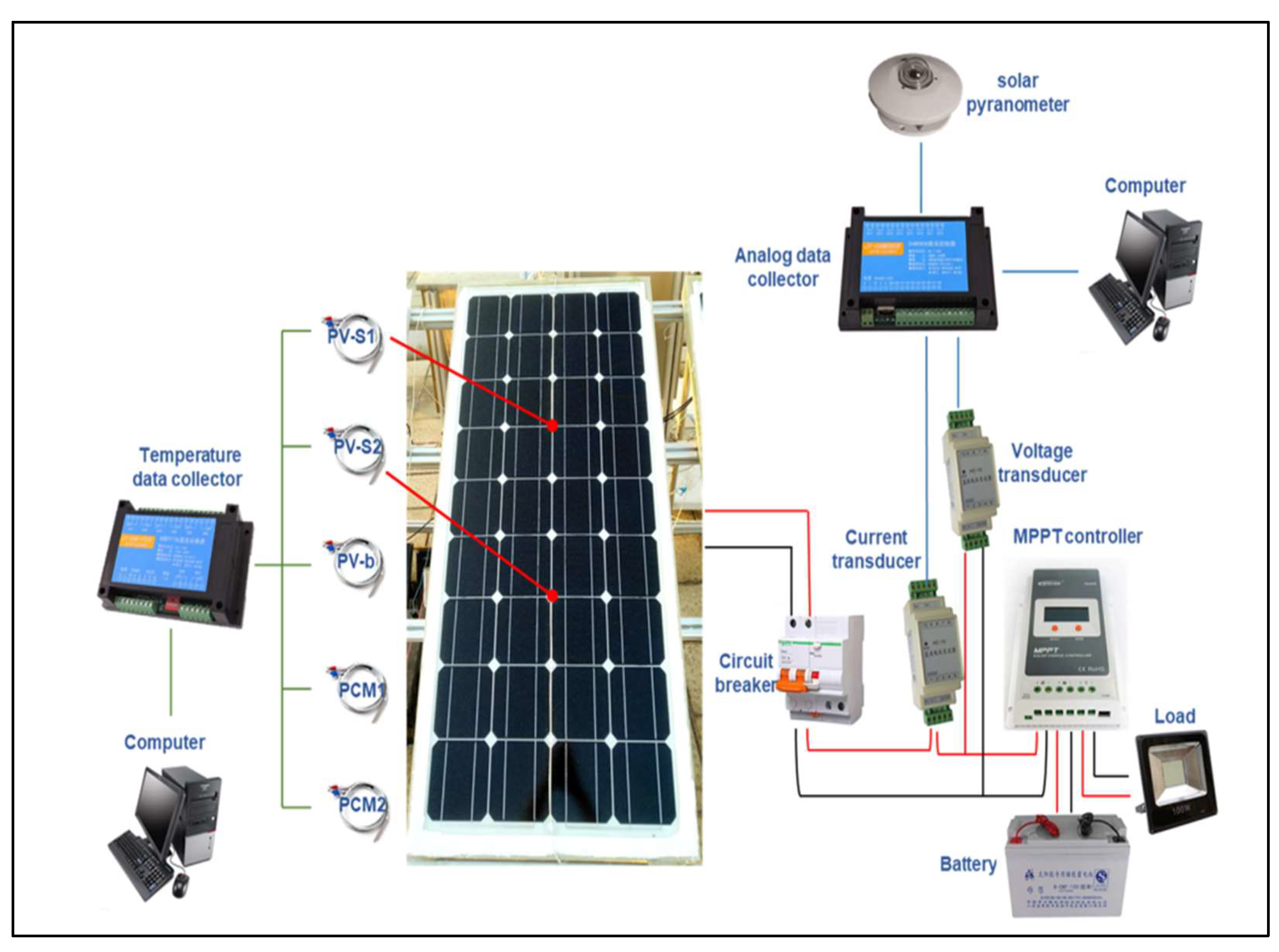
Figure 47.
Return of investment for each cooling solution.
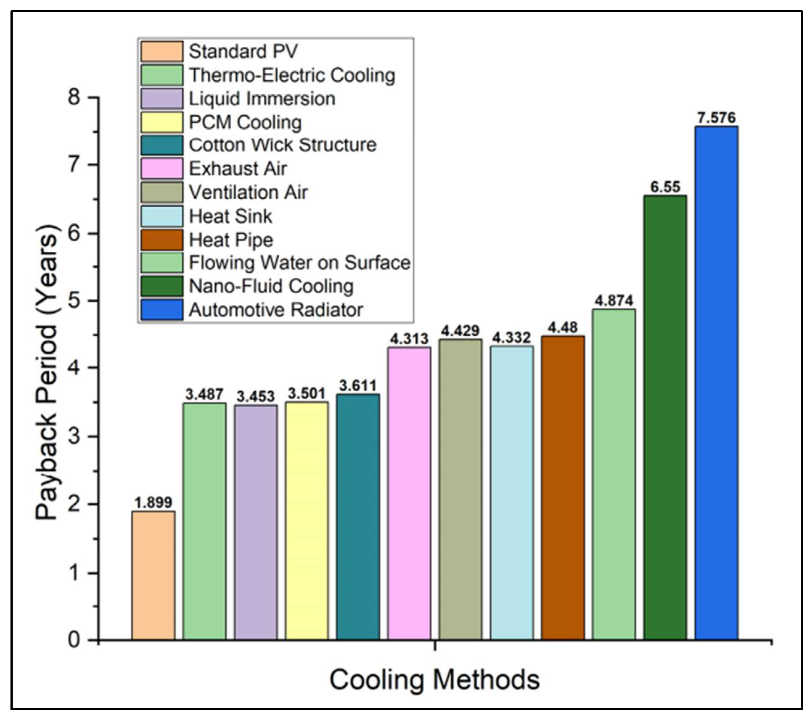

Table 1.
The summary of selected studies of PV panel cooling using heat exchanger.
| Authors | Method used to enhance efficiency | Outcome/Remarks |
| Hamed et al. (2019) [16] |
Dual cooling Technique which involves front and back cooling using copper pipes with heat exchanger. | Temperature dropped significantly. Improves the average electrical PV efficiency. The optimal ratio of nanofluid concentration is 0.3%. The temperature dropped to 45°C, which resulted in improvement of PV efficiency of 10.9%. The optimal flow rate of nanofluid is 2L/min. |
| Nasir et al. (2020) [17] | Copper pipes bent into elliptical shape and bonded thermally to the back of PV panels. Two mono-crystalline and two poly-crystalline were used. | PV modules temperature dropped by 12°C. The mono-crystalline showed more improvement in efficiency (increase of 4.46%) compared to poly-crystalline (increase of 3.45%) |
| Jakhar et al. (2022) [18] | Developed a detail mathematical model of PV/T system with ground coupled heat exchanger (GCHE) with alumina/water nanofluid. | Temperature of PV panel reduced by 2°C. Decrease in temperature difference between the PV/T outlet and inlet by 6°C, an increase in electrical efficiency by 0.1%, and an increase in thermal efficiency by 4%. |
| Rostami et al., (2022) [19] | Nano-graphite/paraffin composite as phase change material(PCM). To slow down the melting of phase change material (PCM), a finned tube-heat exchanger was placed inside the PCM. | Higher water flow rate resulted in lower surface temperature of PV panel. Average surface temperature dropped from 336.15K to 310.25K with the usage of concentration of 0.01(w/v) nano-graphite PCM and water flow rate of 100mLs-1. Maximum enhancement was 21.2% at efficient condition. |
| Fabbri & Greppi (2021) [20] | The thermoelectric generator is included into the heat exchange system, using a fraction of the extracted heat to produce the necessary temperature gradient for the Seebeck effect to produce electrical energy. |
Enhance electrical power by almost 15%. Seebeck effect resulted in additional electrical power ranges from 61.2 to 71.2W. The maximum attainable system electrical power, accounting for all power gains and losses, is approximately 300–310 W/m2. |
| Majeed et al., (2023) [21] | Monocrystalline PV panel and a spiral heat exchanger. A 3U-shaped copper tube is buried at a depth of 4 meters and has a total length of 22.25 meters. |
20°C difference observed between PV standalone and PVT system. The electrical efficiency increased by 127.3%. Water flow rate was 0.18L/s which caused almost zero vibration to the system. |
| Saftoiu & Morega (2023) [22] | Counter flow heat exchanger with pulsed fluid cooling. | The counter flow heat exchanger efficiently decreased the high temperatures on the PV panel. The pulsed cooling method improved the cooling process by periodically infusing cooling fluid resulting improvement in electrical efficiency caused by reduced operating temperatures. |
| Jafari et al., (2021) [23] | Ethylene Vinyl Acetate (EVA) was applied to standard photovoltaic cells before they were linked to a polymer minichannel heat exchanger on the rear and tempered glass on the front. |
The system showed a 10% improvement in daily power production due to efficient heat dissipation maintaining the PV cells at ideal temperatures. |
| Hudișteanu et al., (2020) [24] | Mounting water heat exchangers onto the rear side of the PV panels. |
The panels demonstrated an efficiency of around 11.4% under peak solar radiation. The efficiency was improved by roughly 12.23% with the cooling system operating. |
| Siddiqui et al., (2019) [25] | 14 distinct design criteria include channel numbers, manifold width, and the position and form of inlet/exit ports. |
Specific modifications in the heat exchanger design, such as altering manifold width and including V-shaped outlets, were shown to greatly influence performance by improving flow uniformity and decreasing temperature fluctuations. |
| Elminshawy et al., (2019) [26] | A photovoltaic panel connected to a geothermal air cooling system, particularly an earth-to-air heat exchanger (EAHE). |
The pre-cooled air lowered the PV module’s average temperature from 55°C to 42°C, resulting in an 18.90% increase in electrical output power and a 22.98% improvement in electrical efficiency. The improvements were most effective when the air flow rate was 0.0288 m³/s. |
| Yang et al., (2019) [27] | Incorporating a spray cooling system with a shallow geothermal energy heat exchanger. This system utilized water sprayed onto the back of the PV panels, which was then circulated via a U-shaped borehole heat exchanger (UBHE) to transfer heat with the geothermal energy in shallow soil layers. | The research discovered that implementing this configuration might enhance the panel efficiency by 14.3% in a plant industrial setting, with the equipment expenses of the system expected to be recouped within 8.7 years. |
| Li et al., (2024) [28] | PV/T system integrating a micro heat pipe with double-layer glass and a nanofluid |
During summer, the thermal collection efficiency reached a peak of 39.45%, while the power conversion efficiency peaked at 12.64% in winter. The investigation revealed that utilizing R141b as the operating fluid in the micro heat pipe greatly improved both thermal and power efficiency in comparison to conventional fluids such as acetone. |
Table 2.
The summary of selected studies on photovoltaic panel cooling using nanofluid.
| Authors | Method used to enhance efficiency | Outcome/Remarks |
| Sathyamurthy et al., (2021) [29] | CNT/Al2O3 hybrid nanoparticles. Spiral tube collector and serpentine tube collector were studied | Combination of spiral tube with water and nanofluid improved the electrical efficiency to 7.15% and 8.2% respectively. Power production also increased by 11.7% using water and 21.4% using hybrid nanofluid. Overall enhancement is 27.3% compared to using water as medium. |
| Qeays et al., (2020) [30] | Hybrid photovoltaic thermal system with nanofluid cooling (HPVTS). Taguchi’s L16 orthogonal array. | HPVTS optimal performance was achieved for 800 W/m2 irradiance, 25°C ambient temperature, 0.5 L/min flow rate and 0.5% concentration of nanofluid. |
| Bayoumi et al., (2021) [31] | Uses Comsol Multiphysics software. Utilizes Finite Element Method together with Matlab program to simulate the model. Different back pipes structures. Serpentine and new square shape pipes. Nanofluid Cuo/water is used. |
The power production improved from 223W for serpentine shape to 236W for the square shape with water. Using CuO nanofluid further improved power output to 246W. |
| Khalili et al., (2023) [32] | Cooling duct positioned at bottom of PVT-TEG unit. Hybrid nanofluid Fe3O4 and MWCNT with water. Three cross section configurations (circular, rhombus and elliptic). | Elliptic duct showed the best result with 6.29% improvement. Thermal and electrical performances for elliptic design are 14.56% and 55.42% respectively. Compared to uncooled system the improvement is 16.2%. |
| Abdeldjebar et al., (2023) [33] | Al2O3-water nanofluid with constant horizontal velocity. | The flow intensity was highest near the pipe’s symmetry axis, and the temperature dispersion was enhanced by adding nanoparticles. Higher Reynolds numbers often decrease heat dissipation efficiency, indicating that less velocity might be more advantageous for efficient cooling of solar panels. Higher concentration of nanofluid resulted in better heat transfer. |
| Shahad et al., (2021) [34] | Sic/Water nanofluid used to cool monocrystalline PV panel. Two concentrations of nanofluid 0.1% and 0.5% | Using a 0.5% nanofluid concentration at a flow rate of 2 L/min led to a 50% rise in electrical efficiency and an 82.41% improvement in total efficiency in March. The June observations showed minimal improvements with a nanofluid concentration of 0.1% and a flow rate of 0.5 L/min, resulting in increases of 35.4% and 34.01%, respectively. The experimental findings closely matched the theoretical predictions, with an average variance in electrical efficiency of around 5.58% in March and 11% in June. |
| Ebaid et al., (2020) [35] | Two water based nanofluid used which are titanium dioxide (TiO2) and Aluminum Oxide (Al2O3) with 0.01%, 0.05% and 0.1% wt concentrations. Three monocrystalline silicon PV panel tested. | The Nusselt number investigation showed that the TiO2 nanofluid with a concentration of 0.1 wt% yielded the most effective heat transmission results. |
| Abdollahi & Rahimi (2020) [36] | PCM and Boehmite nanofluid. Nanofluid concentrations used were 0.02, 0.06 and 0.1% wt. Helical tube is used to enhance the cooling. | At a flow rate of 18.91 mL/s, a nanofluid concentration of 0.1 wt.% resulted in the most significant decrease in panel temperature and the greatest enhancement in power output, leading to a 58.8% gain in electrical power efficiency. |
| Ebaid et al., (2018) [37] | Suspension of Al2O3 and TiO2 nanoparticles in water-polyethylene glycol and water- cetyltrimethylammonium bromide. Concentrations used are 0.01, 0.05 and 0.1% wt. Heat exchanger with aluminium rectangular cross-section was fixed to the rear surface of the PV panel | The Al2O3 nanofluid exhibited superior cooling efficiency compared to the TiO2 nanofluid. Increased nanofluid concentrations typically resulted in improved cooling effects over the whole range of flow rates examined. The TiO2 nanofluid improved power and efficiency more effectively than water cooling in different flow rates and concentrations, as shown by electrical performance analysis. |
| Rostami et al., (2018) [38] | The experiment used atomized CuO nanofluid at concentrations ranging from 0.01 to 0.8 w/v, together with atomized pure water as cooling liquids. Nanofluid and high frequency ultrasound were utilized to generate a cold vapor, which was subsequently applied to the PV module to improve cooling and efficiency. | The 0.8 w/v nanofluid with the highest concentration reduced the module’s average surface temperature by 57.25% and increased the maximum amount of power produced by 51.1% compared to the configuration without a cooling system. |
Table 3.
The summary of photovoltaic panel cooling using phase change material.
| Authors | Methods used to enhance efficiency | Outcome/Remarks |
| Vaziri Rad et al., (2021) [39] | Aluminium shaving combined with salt hydrate phase change material (PCM) into a water-based photovoltaic (PV/T) thermal system | Average temperature reduced by 24% and also electrical efficiency by 2.5% compared to standalone PV panel. The melting period of PCM reduced from 19% to 25% due to improved thermal conductivity by the porous material. |
| Kiwan et al., (2020) [40] | PCM used was paraffin graphite panel covered with an aluminium sheet for better heat dissipation | PCM improved the efficiency of the system. The efficiency ranged from 10% to 12%. If the cell temperature doesn’t surpass the melting temperature of PCM it affects the efficiency negatively because the PCM will act as thermal insulator. |
| Aneli et al., (2021) [41] | Rubitherm RT28 and RT35 PCM is combined with PV module | PV-PCMRT35 shows lower temperature the whole day compared to conventional module maximum difference was 20°C at noon. From 6.00am to 10.00am PV-PCMRT28 showed the lowest cell temperature. 10% increase in peak power also 3.5% improvement in annual energy production compared to traditional PV modules. |
| Badi et al., (2023) [42] | PCM-OM37P pack were attached to the rear of the panel | Temperature reduction improved from 5°C to 6°C during peak hours. Voltage drop improvement seen at least 0.6V. Power Enhancement Percentage were around 3% observed. |
| Rajaee et al., (2020) [43] | Cooling with Co3O4/water nanofluid of different concentrations. Another study where PCM (paraffin wax combined with Alumina powder) and nanofluid combined was conducted | Utilizing a 1% Co3O4/water nanofluid as the coolant increased the total electrical efficiency by 12.28% in comparison to utilizing only water. Compared to water cooling, an improved PCM and nanofluid increased exergy efficiency by 11.6%. |
| Bayrak et al., (2020) [44] | Different methods used including PCM, thermoelectric modules (TEM) and aluminum fins | Fins showed highest cooling result which is 47.88W power generated compared to PCM and TEM which resulted in 44.26W. |
| Elavarasan et al., (2020) [45] | OM29 PCM was coated directly to the back of the PV module, removing any barriers to heat conduction and enabling direct heat transfer from the panel to the PCM. |
By integrating OM29 PCM directly on the rear surface of the PV module, the temperature fell by up to 1.2°C by 08:30 AM. After 09:00 AM, OM29 could not continue the cooling effect because it could not preserve the latent heat characteristics for long durations. The PCM back sheet proved poor in dispersing stored thermal energy, rendering it unsuitable for high-temperature applications. |
| Jamil et al., (2021) [46] | Nano phase change material (nano-PCMs). Three different nano-PCMs Combining multiwall carbon nanotubes, graphene nanoplatelets, and magnesium oxide nanoparticles with a phase transition material known as PT-58. Concentrations used are 0.25 wt% and 0.5 wt%. |
The panels coated with 0.5 wt% concentration graphene nanoplatelets/PT-58 nano-PCM showed the greatest decrease in temperature and electrical effectiveness. The biggest temperature decrease recorded was 9.94°C at a concentration of 0.5 wt% of graphene nanoplatelets, while the greatest increase in electrical power was 33.07% for the same setup. |
| Zhao et al., (2019) [47] | Analysis made using 1-D thermal resistance model created with MATLAB. Five distinct photovoltaic-phase change material (PV-PCM) systems were modeled using actual meteorological data from Shanghai in 2017, each including various phase change materials (PCMs). |
The greatest annual increase in power production was around 2.46% when compared to a conventional PV system lacking PCM. |
| Selabi et al., (2021) [48] | Composite PCM-metal matrix implementation. Different PCM were tested which are CaCl2-6H2O, paraffin wax, RT25, RT27, SP29 and n-octadecane paired with metals such as copper, aluminium, steel and nickel and polymers such as polystyrene and polypropylene for composite matrix. | RT25, when combined with a metal matrix, showed superior compatibility by effectively regulating the temperature of the PV cell at lower levels in comparison to other PCM varieties. |
| Marudaipillai et al., (2023) [49] | Uses polyethylene glycol/expanded graphite to create a stable phase change material (FSPCM) |
With reductions of 11.5°C for the FSPCM setup and 9.45°C for the heat sink setup, the application of FSPCM led to a notable decrease in PV panel surface temperature when compared to the heat sink approach. The FSPCM-equipped PV panel demonstrated an overall efficiency improvement of 3.667%, outperforming the typical cooling technology (heat sink) which achieved 1.072%. |
| Karthikeyan et al., (2020) [50] | A thermal heat transfer network was created to enhance the efficiency of the PV module by utilizing radiation mode to address the problem of PCM re-conduction. | The PV module with composite PCM achieved an efficiency of 14.75% and a temperature of 47.81°C when the optimum thickness of 2.5 cm was used. The results showed that the composite PCM had superior thermal conductivity, leading to improved heat dissipation compared to pure PCM. |
| Arıcı et al., (2018) [51] | A numerical model is concentrated on maximizing the parameters of the PCM layer. Numerical analysis using a one-dimensional finite volume approach. | The findings demonstrated that PV panels’ working temperature can be considerably lowered by up to 10.26°C when PCMs are used, leading to an increase in efficiency of up to 3.73%. |
Disclaimer/Publisher’s Note: The statements, opinions and data contained in all publications are solely those of the individual author(s) and contributor(s) and not of MDPI and/or the editor(s). MDPI and/or the editor(s) disclaim responsibility for any injury to people or property resulting from any ideas, methods, instructions or products referred to in the content. |
© 2025 by the authors. Licensee MDPI, Basel, Switzerland. This article is an open access article distributed under the terms and conditions of the Creative Commons Attribution (CC BY) license (http://creativecommons.org/licenses/by/4.0/).
Copyright: This open access article is published under a Creative Commons CC BY 4.0 license, which permit the free download, distribution, and reuse, provided that the author and preprint are cited in any reuse.


