Submitted:
09 April 2025
Posted:
11 April 2025
You are already at the latest version
Abstract
Currently, the Ultra-Wide Band (UWB) technology commercialized in smartphones and smart keys is a High Rate Pulse repetition frequency (HRP) UWB of the IEEE 802.15.4z standard, which aims to accurately determine the distance between UWB devices located within tens of meters using Two Way Ranging (TWR). However, in order for UWB ranging technology to be spread to various location-based services or positioning services, it must be able to measure the distance between UWB devices that are hundreds of meters apart. Fortunately, UWB technology can freely change physical layer parameters as long as it complies with the UWB local regulation worldwide. Therefore, in this study, we analyzed the method of configuring packet structure, length, and transmission power from the link budget perspective to enable longer UWB ranging of hundreds of meters within UWB local regulations. As a result of the analysis, we theoretically confirmed that UWB ranging is possible even at hundreds of meters by selecting the optimal physical layer parameters. In addition, the experimental results using the Qorvo DW3000 module were confirmed to be consistent with the results analyzed in this study. The results of this study can be used as a basic data for the introduction of wide-area UWB technology and services in the future.
Keywords:
UWB
; HRP UWB
; Positioning
; Ranging
; IEEE 802.15.4z
; Link Budget
; IoT
1. Introduction
Ultra-Wide Band (UWB) technology has gained attention in various fields due to its potential for precise distance measurement, ranging. In particular, the High Rate Pulse repetition frequency (HRP) UWB defined in the IEEE 802.15.4z standard has recently become prominent for enabling centimeter-level ranging accuracy between UWB devices [1,2]. This UWB technology first appeared as a short-range wireless personal area network (WPAN) technology in the early 2000s. It was standardized by the IEEE 802.15.4 committee, a WPAN standardization organization, and was announced as the IEEE 802.15.4a standard in 2007. However, UWB technology has not been widely adopted as a WPAN communication technology due to competing technologies such as Wi-Fi and Bluetooth [3,4]. However, as the increasing demand for location-based services in IoT, smart factories, and other applications, UWB technology has been re-evaluated for its advantage of being able to measure the distance between UWB devices in addition to providing wireless communication. Since Apple’s iPhone 11 in 2019, which launched a service that informs the location of nearby UWB devices, most smartphones released by Samsung, Apple, and Google on the market today have integrated HRP UWB technology. In addition, automobile companies such as Hyundai Motors are also introducing UWB smart keys [5,6]. Following this trend, HRP UWB has continued to improve its performance with the announcement of the IEEE 802.15.4z standard in 2020, and the IEEE 802.15.4ab standardization work is currently in progress [5,6,7,8,9].
Since HRP UWB was originally introduced as a short-range precision ranging solution, not a long-range communication solution, there has been no meaningful attempt to expand the ranging coverage. Moreover, since HRP UWB has been mainly applied to smartphones, its function has been limited to measuring the exact distance between nearby UWB devices after pairing via Bluetooth. Most smartphones first recognize UWB devices through Bluetooth pairing before performing UWB ranging to reduce power consumption in UWB raging operation. As a result, the HRP UWB ranging was constrained to several tens of meters, equivalent to the Bluetooth communication range. This trend is also true for HRP UWB applications other than smartphones. Most of the existing studies on IEEE 802.15.4z HRP UWB investigated by the authors have focused on improving ranging accuracy, ensuring communication robustness, and mitigating interference with Wi-Fi 6E [10,11,12,13,14,15,16,17,18,19,20]. Table 1 summarizes the operation ranges reported in prior studies, with most commercially available modules (e.g., Qorvo’s DWM1000, DW3000, DW3120; NXP’s SR150 and SR040; and Spark’s SR1010 and SR1020) being limited to approximately 50 or 100 m.
Nevertheless, for IEEE 802.15.4z UWB technology to be widely used beyond smartphones and smart keys, it must be able to measure the distance between UWB devices that are hundreds of meters apart. If a longer operating range is possible beyond the current operating range limit of tens of meters, HRP UWB communication technology can be widely used in various fields such as logistics, smart factories, and smart cities. Therefore, in this study, we propose a method to extend the ranging capability of IEEE 802.15.4z HRP UWB systems to hundreds of meters. This is achieved through a detailed link budget analysis considering packet structure, packet length, and transmission power within the worldwide UWB local regulation. Our results show that by optimizing the physical and RF parameters based on a detailed link budget analysis that accounts for the inherent link performance imbalance between the SYNC (preamble) and the Data Portion (DP), UWB systems can achieve significantly extended ranging without violating power emission limits. This improvement is not merely a result of increasing output power, but rather of addressing the link performance difference. By reducing the link differences between the SYNC and the DP, the overall packet reception performance is improved. Thus, the extended ranging capability is quantitatively supported by a more balanced and favorable link budget distribution across the full packet structure. We also experimentally verify the proposed method using Qorvo DW3000, and the experimental results are consistent with the theoretical analysis. Our experimental results show that by tuning these parameters while respecting the local regulation power constraints, a longer UWB operating range can be achieved.
The composition of this paper is as follows: First, in Section II, we explain the characteristics of HRP UWB technology based on the UWB local regulation. Then, in Section III, we analyze the link performance of IEEE 802.15.4z HRP UWB communication and analyze the parameters for long-ranging measurement of HRP UWB. In Section IV, we describe the experimental method and experimental results to verify these analysis results, and finally, in Section V, we conclude.
2. UWB Local Regulations and UWB Pulse Characteristics
UWB means using an ultra-wideband, and the local regulations in Table 2 must be applied worldwide. As shown in Table 2, UWB is regulated frequency-related regulations, such as the frequency band or frequency bandwidth used, and output power, such as average power and peak power. Among the local regulations in Table 2, the output power regulations are applied globally. That is, the output power of the UWB transmitter must satisfy both ① the average power spectral density (PSD) of -41.3 dBm/MHz at 1 msec and ② the peak PSD of 0 dBm/50 MHz. This is explained in Figure 1. Assuming that one pulse has a bandwidth of 500 MHz, the pulse width is approximately 2 nsec. The peak power of one 2 nsec pulse must be less than 10 dBm/500 MHz according to ② the peak PSD regulation. In addition, when there are multiple pulses during a 1 msec period, the average power, which is the accumulated effect of these pulses, must be less than –14.3 dBm/500 MHz according to ① the average PSD regulation.
The reason for having two criteria like this is because the average power changes depending on the number of pulses. For example, if there is only one pulse with a bandwidth of 500 MHz per 1 msec, as shown in Figure 1(a), the peak power will have a very large value of 42.7 dBm/500 MHz by ① the average PSD regulation. This means that although the average output is small, the peak power is very large, so it can interfere with other wireless devices for a short period of time. Therefore, according to local regulation of ②, the peak power must be limited to 10 dBm or less even if there is one pulse. Accordingly, the case where both local regulations are satisfied is when the peak power is 10 dBm and the number of pulses is 1862 for a UWB pulse with a bandwidth of 500 MHz, as shown in Figure 1(b). In this case, the average power becomes -14.3 dBm/500 MHz, so both local regulations ① and ② are satisfied.
Now, based on this local regulation for output power, let’s find out the number of pulses per 1 msec, peak power, and average power when a UWB device is used for communication or radar. First, since UWB radar measures the distance using the time difference between the transmitted pulse and the pulse backscattered from the target, the pulse repetition frequency (PRF) is determined by the maximum measurement distance. For example, Novelda’s UWB x4 module, a representative UWB radar module, uses a pulse with a bandwidth of 1.5 GHz (~pulse width of approximately 0.67 nsec) and waits for the pulse for 65.8 nsec after transmitting the pulse [27]. When this time is converted into a distance, it is 9.87 m. Since the actual operating range of Novelda’s UWB radar is only 1 to 2 m, it is possible to use more pulses, but in this case, the average power exceeds -14.3 dBm/MHz, so it cannot be used. That is, the pulse number and peak power of the UWB radar are determined by local regulations ① and ②, as shown in Figure 2a.
Next, the currently commercialized IEEE 802.15.4z-based UWB communication is the HRP UWB with a relatively high PRF [7]. In Figure 1, when the peak power is 10 dBm, the number of pulses with a bandwidth of 500 MHz possible for 1 msec is 1862, and using more pulses than this number is called HRP UWB. As shown in Figure 2b), when the number of pulses increases, the peak power becomes smaller than the value of local regulation ②. Instead, by using a large number of pulses, additional processing gain can be obtained through spread spectrum. However, since the number of pulses cannot be increased indefinitely, it must be limited so as not to exceed the average power suggested in local regulation ①. In other words, in order to increase the processing gain, the more pulses the better, but the number of pulses cannot exceed the local regulation for average power. Since UWB communication must maintain -14.3 dBm according to the average power local regulation ①, HRP UWB communication becomes a system whose performance is limited only by the average power regardless of the peak power.
3. Link Analysis of HRP UWB Communication
3.1. Packet Structure of HRP UWB
In the previous section, we examined that HRP UWB communication is a system whose performance is limited only by average power. In this section, we will examine how this principle is implemented in the actual IEEE 802.15.4z HRP UWB standard. Figure 3 shows the packet structure presented in the IEEE 802.15.4z HRP UWB standard [5,7]. As shown in Figure 3, the packet structure of IEEE 802.15.4z HRP UWB is divided into Synchronization Header (SHR) used to set the reference time for synchronization and distance measurement and Data Portion (DP) for transmitting data, and the two use separate modulation methods. The IEEE 802.15.4z HRP UWB standard also includes a Scrambled Time Sequence (STS) for encrypted distance measurement, but since STS uses the same modulation as SHR, Figure 3 shows a packet without STS.
First, the SHR is divided into a preamble and Start-of-frame-delimiter (SFD). The preamble is transmitted by repeating the same symbol, and its length is determined by the number of Preamble Symbol Repetitions (PSR). One preamble symbol is defined by 31 or 127 sub-symbols, and each sub-symbol has a value of (-1, 0, 1). Here, ‘1’ means a UWB pulse with positive (+) polarity, ‘-1’ means a UWB pulse with negative (-) polarity, and ‘0’ means no pulse. These pulses have a time interval of the inverse of the PRF. The Basic PRF (BPRF) mode of the IEEE 802.15.4z standard uses a PRF of 64 MHz. Next, the SFD consists of 8 or 64 symbols and indicates the end of the preamble and the start of DP. The preamble can obtain processing gain by repeatedly sending a known pulse without any special modulation. In HRP UWB, this is defined as the number of Packet Acquisition Chunks (PAC). In addition to the processing gain by PAC, the preamble uses the Leading Edge Detection (LED) algorithm to increase the ranging accuracy. That is, if the number of PSRs is 1024 and the PAC is 32, one channel impulse response (CIR) is generated by collecting preambles of 32 PACs, and the LED algorithm is used to increase the ranging accuracy by using 32 (=1024/32) of these CIRs [1].
Next, DP consists of the Physical Header (PHR) and the payload. PHR includes information about the length and speed of payload data and uses different channel coding and modulation schemes from SHR. Reed-Solomon (RS) coding and convolutional coding are used for channel coding, and Burst Position Modulation – Binary Phase Shift Keying (BPM-BPSK) modulation is used as a modulation method. This is because, unlike SHR, pulses are not sent repeatedly in the data section, so there is no processing gain, but instead, coding gain is obtained through channel coding to balance the link between the preamble and payload. In HRP UWB communication, the ranging limit is determined by the link margin smaller between the SHR link and the DP link, so it is necessary to adjust the parameters so that the two links are appropriately balanced.
3.2. Communication and Ranging Principles of HRP UWB
Section 3-1 explains the structure and modulation method of the physical layer packet of the IEEE 802.15.4z HRP UWB standard. This section examines the principle of how HRP UWB technology measures distance based on wireless communication. Since HRP UWB is basically a wireless communication method, packets are exchanged to send and receive data. Among the packets, the preamble performs the role of synchronization for data demodulation, and the payload among DPs is used for data transmission. The principle of ranging between UWB devices using this packet exchange is as shown in Figure 4a. Figure 4a is a method of measuring distance by exchanging only two packets, which is called Single Sided Two Way Ranging (SS-TWR). Among the two UWB devices, the device that sends the packet first is called the Initiator, and the other is called the Responder. The Initiator transmits a Poll packet and records the time when the transmission of the Poll packet begins. is the moment when the preamble ends, and this time record is called a timestamp. The UWB Responder device that received the Poll message sends a Response packet after the time. Now, the UWB Initiator records the time at which the Response packet was received as a timestamp . Now, the distance between the two UWB devices is 1/2 of the time of propagation (ToF), so it is given by Equation (1).
where, means the speed of light. In this way, ranging using two packets is possible through wireless communication, and this is called two-way ranging (TWR).
Meanwhile, the types of TWR that measure distance in UWB can be divided into SS-TWR that exchanges packets twice (Poll-Response) and Double Sided-TWR (DS-TWR) that exchanges packets three times (Poll-Response-Final) and, as shown in Figure 4(b). DS-TWR is further classified into Symmetrical DS-TWR (SDS-TWR) and Asymmetrical DS-TWR (ADS-TWR). Among these, ADS-TWR, which can freely use the length of the packet, is mainly used for ranging. ADS-TWR is used when high distance accuracy is required because it can minimize the influence of clock errors between transmitter and receiver. In ADS-TWR, the length of the packet is the shortest for the Poll packet and the longest for the Final packet, as shown in Figure 4b. Regardless of the TWR method used, in order to measure the distance between UWB devices with TWR, two packets must be successfully exchanged for SDS-TWR and three packets must be successfully exchanged for DS-TWR. To this end, both the preamble and the payload of the packets must be successfully received.
3.3. Link Analysis of Data Portion in TWR Procedure
In order for the TWR process of HRP UWB explained in Section 3-2 to be successful, packets related to ranging must first be successfully exchanged. To this end, there must be no preamble errors and no DP data errors. In other words, the link budget of the preamble and the link budget of the DP must be considered simultaneously.
First, let’s look at the DP link. The link performance of DP is determined by whether the packet reception is successful or not, and is usually given as Packet Error Rate (PER). In this study, we assume a PER of 1% or more as the link performance criterion. This value is a value commonly discussed in the current next-generation UWB standard, IEEE 802.15.4ab [8]. The PER performance of BPM-BPSK used in UWB communication is generally given as Equation (2) [28].
where, is the number of bits per packet, is the coding gain, is the bit energy, and is the power density spectrum of noise. As shown in Figure 4b, ‘Poll’, ‘Response’, and ‘Final’ packets are required for ADS-TWR, and the longest packet is the ‘Final’ packet with a size of 24 bytes, so this packet should be used as the criterion for PER evaluation. That is, since N is 192 bits, of the DP corresponds to 9.0 dB assuming 1% PER. Next, the IEEE 802.15.4z HRP UWB standard uses convolutional channel coding and Reed Solomon channel coding, so it has a channel coding gain of about 5.6 dB [13]. Therefore, the DP of the IEEE802.15.4z HRP UWB standard should have a value of about 3.4 dB [22]. In addition, since the IEEE802.15.4z HRP UWB standard spreads one bit over multiple chips, the Signal-to-Noise Ratio (SNR) is given by Equation (3).
where, is the bandwidth, is the bit rate, and is the chip rate. Based on the IEEE 802.15.4z HRP UWB standard, when is 850 kbps, the SNR is calculated to be about –24.3 dB, and when is 6.8 Mbps, the SNR is calculated to be –15.3 dB. That is, if the data rate is as low as 850 kbps, there is a 9 dB link margin, so a wider communication range can be achieved than in the case of 6.8 Mbps.
Now that we know the SNR value, let’s analyze the DP link based on the transmitter parameters of the IEEE 802.14z HRP UWB standard and the power regulation in Table 2. The transmitted power is given by Equations (4).
where, is the transmitted power of the preamble in dBm, is the average power regulation of -41.3 dBm/MHz, means the bandwidth in dBMHz, and is the gating gain, respectively. The gating gain is given by Equation (5).
where, corresponds to the time length of the packet. In other words, if the packet length is less than 1 msec, it indicates that the output can be increased by that amount according to the local regulation. Figure 5 shows a case where the output power is doubled by GG when is 0.5 msec. Typically, UWB IC manufacturers such as Qorvo and NXP provide a function that can control power through gating gain if the packet length is shorter than 1 msec [22]. Finally, the receiver sensitivity is given by Equation (6).
where, is the minimum SNR, which is given by Equation (3), and is receiver’s noise figure. Finally, the received power is calculated based on the Friis transmission formula, which is a path loss model in free space.
3.4. Link Analysis of Preamble in TWR Procedure
In Section 3-3, we analyzed the link characteristics in the DP of HRP UWB. In this section, we analyze the ranging accuracy when data is successfully exchanged. In UWB communication, the ranging accuracy is related to the preamble, and the Root Mean Square (RMS) value of the ranging accuracy of the preamble is given by the Cramer-Rao Bound (CRB). In general, the RMS of the ranging accuracy is given as a function of SNR and effective bandwidth as in Equation (7) [28,29].
where, is the speed of light, is the signal-to-noise ratio of the preamble, and is the effective bandwidth, which corresponds to 500 MHz in the case of IEEE 802.15.4z HRP UWB standard [9]. Based on Equation (7), the ranging accuracy is expressed as a function of SNR and effective bandwidth as in Figure 6.
If the ranging accuracy is 1 cm, the SNR of the UWB preamble requires 16 dB by Equation (7). In other words, unlike the SNR value required by the DP in the UWB packet, the preamble requires a 12.6 dB higher SNR value. To this end, the SNR value is increased by repeatedly transmitting the same symbol in the preamble. At this time, the processing gain is given by the number of symbol repetitions as in equation (8).
Where,means the number of symbols used for ranging in the preamble. The number of symbols to be used for the processing gain of equation (8) among the number of symbols in the preamble is defined by PSR and PAC. Now, the transmitted power of the preamble of the HRP UWB preamble is given as equation (9) because the processing gain is added, unlike equation (4).
Where, is the transmitted power of the preamble in dBm, is the average power regulation of -41.3 dBm/MHz, means the bandwidth in dBMHz, and are the gating gain and the processing gain, respectively. Finally, the received power is based on the Friis transmission formula, which is a path loss model in free space.
Now, using equations (3) to (9), the link budget for each preamble and DP of IEEE 802.15.4z UWB communication is calculated as shown in Table 3. In Table 3, CH9, which is currently available worldwide, was used as the UWB frequency. Among the results in Table 3, the preamble link and the DP link with a data transmission rate of 6.8 Mbps are represented graphically as shown in Figure 7. As can be seen in Table 3, the link performance of the preamble is better than that of the DP. In other words, when the distance increases, the preamble may be received but the data link may be broken. This has been experimentally presented in related papers [31,32]. In addition, it can be seen that in the DP, sending data at a low speed of 850 kbps rather than a data rate of 6.8 Mbps can improve the performance by about 9 dB. This is consistent with the results provided by the chip manufacturer [22].
Our analysis results are summarized in Figure 8. The ranging coverage of UWB communication at a data rate of 850 kbps is more than twice as large as that at a data rate of 6.8 Mbps. The link performance of preamble, which is the basis for synchronization and ranging, varies depending on the length of the preamble. In the IEEE 802.15.4z HRP UWB standard, the length of the preamble varies from a minimum of 16 to a maximum of 4096, so a longer preamble has a larger ranging coverage than for a shorter preamble. However, since the message must be successfully received for two way ranging, the characteristics of the preamble need to be appropriately adjusted to the link of the data portion. After the link balance of the DP section and the SYNC section is matched, it is possible to additionally increase the transmission power using the gating gain if the packet length is less than 1 msec. This has been confirmed to be consistent with the results of many experimental papers. These results of this study can help to adjust the physical layer parameters when installing actual HRP UWB products to increase the ranging coverage.
4. Experimental Results and Discussion
In Section 3, the link performance required in the preamble and DP was theoretically analyzed. In this section, we verify the theoretical results through experiments using an actual HRP UWB module. In the experiments, we verify the performance changes according to the changes in PHY parameters such as PSR, PAC, and data rate (850 kbps vs. 6.8 Mbps) and the possibility of longer ranging. In particular, we verified the following results examined in the theoretical analysis through this experiment. First, since the link margin of the preamble is theoretically higher than that of the DP, errors may occur in the DP of the packet at a long distance, but the preamble-based synchronization signal will still be able to be received. Second, low-speed data (850 kbps) will show about 9 dB of performance gain compared to high-speed data (6.8 Mbps) as analyzed in the theory. Third, the processing gain will be increased according to the increase in the PAC size and PSR length, which will improve the distance measurement accuracy and stability. To verify these three points, the experiment was conducted as follows.
4.1. Experiments on Link Performances at Fixed Distance
Figure 9 shows the hardware used in the experiment and the communication link experimental environment at a fixed distance of 10 m. The Qorvo DW3000 HRP UWB IC was controlled by the NRF52840-DK microcontroller board, and the PHY parameters such as PSR, PAC, and data rate could be flexibly set through the embedded programming of the microcontroller. The output of the transmitter was adjusted in 1 dB units to reproduce various link conditions. In the first experiment, the SHR reception rate (HRR) and the packet reception rate (PRR) including SHR and DP were measured while changing the parameters and transmitter output at a fixed distance of 10 m to verify the link budget difference between the preamble and DP. Through this, the difference in the reception of the preamble and DP of the packet was quantitatively compared. The experiment used the SP0 packet format of IEEE 802.15.4z, and the RF parameters were set as specified in Table 4. In this experiment, PSR was fixed to 128 and PAC was fixed to 8. Qorvo’s DW3000 UWB IC provides a function to adjust the transmit power to compensate for the difference between the RF output of the chip and the actual RF output and the antenna loss [22]. For example, it supports a maximum output of -41.3 dBm/MHz while complying with the spectrum emission regulations, and is adjustable from 0 dB up to -30 dB. In this experiment, packets were transmitted while adjusting the TX power gain of the transmitter in 1 dB units. In order to analyze the reception status of the HRP UWB IC and the success or failure of packet reception, register values such as RXPHD (Receiver PHY Header Detect) and RXPHE (Receiver PHY Header Error) of the System Status register (SYS_STATUS) were monitored, and 200 packets were transmitted for each experimental condition. Through this experiment, we could find out whether the packet was received, the error rate of the DP, and compare and analyze the PER performance between the preamble and the DP.
Figure 10 shows the packet reception characteristics as a function of the transmission power through the Coarse and Fine gain adjustments in the DW3000 IC. The experimental results show that the reception success rate of about 80% or higher is achieved from -17 dB at 850 kbps, while the same reception success rate is achieved from about -11 dB at 6.8 Mbps. This means that the low-speed (850 kbps) data transmission provides about 6 dB of link gain compared to the high-speed (6.8 Mbps) data transmission. The reason why a gain of 6 dB is observed, which is slightly smaller than the theoretically suggested 9 dB, is probably due to the interaction between the synchronization performance in SYNC (preamble) and the reception performance in DP, which was not considered in the link analysis. That is, in the case of 6.8 Mbps, stable reception was possible in the SYNC, but due to insufficient link margin in DP, there was an overall link performance difference of about -6 dB, whereas in the case of 850 kbps, the reception performances of SYNC and DP sections were similarly close, showing that the insufficient link margin of SYNC also affected the DP performance. Through this, the link budget difference between the preamble and DP was clearly revealed in the experiment, and the link difference according to the change in data transmission speed could be quantitatively confirmed.
4.2. Maximum Ranging Experiment According to PSR and PAC Size
The second experiment was conducted to identify the maximum communication distance and stable ranging measurement conditions in an actual sports field environment. The measurement environment was conducted at athletic field of Kookmin University in Seoul, the Republic of Korea, as shown in Figure 11. The maximum ranging distance satisfying a packet reception success rate of 90% was measured by changing parameters such as PSR and PAC, and the distance values at that time were organized as median values. Through this process, it was possible to confirm how the processing gain according to PSR and PAC affects the actual long-distance ranging performance. The experimental conditions are as shown in Table 4, and the same SP0 packet format as the first experiment was used, but the ranging measurement was performed in the DS-TWR method. The preamble used low-speed data transmission (850 kbps) to be suitable for long-distance ranging. Through these settings, it was possible to confirm how much the processing gain in the preamble contributes to the actual maximum ranging measurement. The coverage of ranging satisfying a success rate of 90% or more was compared and analyzed by changing the PSR and PAC values step by step.
Figure 12 shows the results for the maximum ranging distance according to the PAC size and PSR length. As can be seen in the figure, the interaction between PAC and PSR has a significant impact on the ranging performance. The ranging performance comparison according to the change in PAC size showed excellent performance in the order of 32, 16, 4, and 8, and in particular, the lowest performance was shown overall when the PAC size was 8. It was confirmed that the maximum ranging performance improved by 2–3 times just by changing the PAC size from 8 to 16. This confirms that the processing gain secured by the increase in PAC size greatly contributes to the longer ranging coverage. In addition, Figure 12 shows that the link performance of SYNC and DP is balanced at 256 PSR, as analyzed in Figure 9, and there is no significant change even if the PSR is increased beyond that. Therefore, it shows that the operating range can be further expanded through the gating gain after fixing the PSR to 256. In an experiment where the output was increased after fixing the PSR to 256, it was confirmed that stable ranging measurement was possible at a distance of more than 300 m.
As shown in Figure 12, the ranging coverage increased as the PSR increased in the order of [64, 128, 256, 512, 1024, 4096]. However, the PSR effect was found to be interrelated with the PAC size. Specifically, when the PAC size was set to 4 or 8, the distance measurement performance tended to remain below 100 m overall. On the other hand, when the PAC size was set to 16 or 32, the distance measurement capability was significantly improved as the PSR increased. In particular, the performance improvement effect was remarkable when the PSR increased in the order of [64, 128, 256], and the best distance measurement performance was observed overall when the PAC size was set to 32. However, the performance improvement due to the increase from 16 to 32 was relatively limited compared to when the PAC size was increased from 8 to 16.
Through this experiment, it was found that increasing the PAC and PSR significantly improved the link margin in the SHR section, leading to a significant improvement in the maximum distance measurement. However, if the link margin of the DP was relatively insufficient, even if the gain was secured in the SYNC section, the success rate was rapidly reduced beyond a certain distance, showing a limitation. In addition, as PSR increases, the processing gain in the SYNC section increases, but the overall packet length increases, which may hinder resource utilization in terms of gating gain utilization and simultaneous access performance of multiple tags. This means that the link margins of the SYNC and DR sections are complementary, and that the optimization of both areas must be performed simultaneously during system design to simultaneously maximize the actual long-distance measurement stability and performance. In summary, this experiment verified that the long-distance measurement performance and stable distance measurement capability can be significantly improved by adjusting the PAC size and PSR length of the preamble while keeping the DP speed at a low speed of 850 kbps. This shows that PAC and PSR parameter optimization is necessary when designing a UWB-based long ranging system.
5. Conclusions
In this study, we analyzed the link performance of the IEEE 802.5.4z HRP UWB standard, which has been commercialized in various fields recently, from the perspective of the link budget, and proposed a method for configuring the optimal HRP UWB parameters for long-distance ranging up to hundreds of meters based on this. Since UWB technology allows for various wireless link designs as long as it satisfies the technical criteria, we confirmed that ranging up to hundreds of meters is possible if designed optimally. The results analyzed in this study were tested with an actual commercial UWB module and used a non-directional antenna. Therefore, if an actual directional antenna is used, the possibility of long-distance ranging of hundreds of meters or more will increase even more. Through the results of this study, we expect that UWB technology can be used in various applications that require long-distance ranging in the future.
Author Contributions
Conceptualization, S.H.; Methodology, B.J, Software, S.H.; data curation, S.H.; Writing—Original Draft Preparation: S.H.; Writing—Review and Editing: B.J. Visualization: S.H.; Supervision, B.J.; Project Administration, B.J. All authors have read and agreed to the published version of the manuscript
Funding
This research received no external funding.
Institutional Review Board Statement
Not applicable.
Informed Consent Statement
Not applicable.
Data Availability Statement
Data sharing not applicable.
Conflicts of Interest
The authors declare no conflict of interest.
Abbreviations
The following abbreviations are used in this manuscript:
| UWB | Ultra-wide band |
| HRP | High Rate Pulse repetition frequency |
| WPAN | Wireless Personal Area Network |
| PSD | Power Spectral Density |
| PRF | Pulse Repetition Frequency |
| SHR | Synchronization Header |
| DP | Data Portion |
| STS | Scrambled Time Sequence |
| SFD | Start-of-Frame-Delimiter |
| PSR | Preamble Symbol Repetitions |
| PAC | Packet Acquisition Chunks |
| LED | Leading Edge Detection |
| CIR | Channel Impulse Response |
| PHR | Physical Header |
| RS | Reed-Solomon |
| BPM-BPSK | Burst Position Modulation – Binary Phase Shift Keying |
| SS-TWR | Single Sided Two Way Ranging |
| DS-TWR | Double Sided Two Way Ranging |
| SDS-TWR | Symmetrical DS-TWR |
| ADS-TWR | Asymmetrical DS-TWR |
| PER | Packet Error Rate |
| SNR | Signal-to-Noise Ratio |
| RMS | Root Mean Square |
| CRB | Cramer-Rao Bound |
References
- Jang, B.J. Principles and Trends of UWB Positioning Technology. J. Korean Inst. Electromagn. Eng. Sci. 2022, 33, 1–11. [Google Scholar] [CrossRef]
- Al-Okby, M.F.R.; Junginger, S.; Roddelkopf, T.; Thurow, K. UWB-Based Real-Time Indoor Positioning Systems: A Comprehensive Review. Appl. Sci. 2024, 14, 11005. [Google Scholar] [CrossRef]
- Bluetooth SIG. Bluetooth Core Specification, Version 5.0. Bluetooth Special Interest Group. 2016. Available online: https://www.bluetooth.com/specifications/specs/core-specification-5-0/.
- Gast, M. Wi-Fi: The Definitive Guide, 2nd ed.; O’Reilly Media, 2005. [Google Scholar]
- Sedlacek, P.; Slanina, M.; Masek, P. An Overview of the IEEE 802.15.4z Standard and Its Comparison to the Existing UWB Standards. In Proceedings of the 2019 29th International Conference Radioelektronika (RADIOELEKTRONIKA), Pardubice, Czech Republic, 16–18 April 2019; IEEE: Piscataway, NJ, USA, 2019; pp. 1–6. [Google Scholar] [CrossRef]
- Corbalán, P.; Picco, G.P. Ultra-wideband Concurrent Ranging. ACM Trans. Sens. Netw. 2020, 16, 41. [Google Scholar] [CrossRef]
- IEEE. IEEE Standard for Low-Rate Wireless Networks—Amendment 1: Enhanced Ultra Wideband (UWB) Physical Layers (PHYs) and Associated Ranging Techniques; IEEE Std 802.15.4z-2020; IEEE: New York, NY, USA, 2020. [Google Scholar]
- Kabbinale, A.R.; Bansal, A.; Gopalan, K.S. Towards Next-Generation Ultra-Wideband Technology. In Proceedings of the 2023 15th International Conference on COMmunication Systems & NETworkS (COMSNETS), Bengaluru, India, 3–8 January 2023; IEEE: Piscataway, NJ, USA, 2023; pp. 280–287. [Google Scholar] [CrossRef]
- Domuta, I.; Palade, T.P.; Puschita, E.; Pastrav, A. Timestamp Estimation in P802.15.4z Amendment. Sensors 2020, 20, 5422. [Google Scholar] [CrossRef] [PubMed]
- Kim, C.J.; Han, B.K.; Lee, J.Y.; Jung, S.W.; Jang, B.J. Sensor Application Using UWB Communication: In-Vehicle Seat Occupancy Detection. J. Korean Inst. Electromagn. Eng. Sci. 2023, 34, 249–255. [Google Scholar] [CrossRef]
- Ahmed, S.; Cho, S.H. Hand Gesture Recognition Using an IR-UWB Radar with an Inception Module-Based Classifier. Sensors 2020, 20, 564. [Google Scholar] [CrossRef] [PubMed]
- Shah, S.; Chaiwong, K.; Kovavisaruch, L.-O.; Kaemarungsi, K.; Demeechai, T. Antenna Delay Calibration of UWB Nodes. IEEE Access 2021, 9, 63294–63305. [Google Scholar] [CrossRef]
- Elsanhoury, M.; Mäkelä, P.; Koljonen, J.; Välisuo, P.; Shamsuzzoha, A.; Mantere, T.; Elmusrati, M.; Kuusniemi, H. Precision Positioning for Smart Logistics Using Ultra-Wideband Technology-Based Indoor Navigation: A Review. IEEE Access 2022, 10, 44413–44445. [Google Scholar] [CrossRef]
- Ma, J.; Zhang, F.; Jin, B.; Su, C.; Li, S.; Wang, Z.; Ni, J. Push the Limit of Highly Accurate Ranging on Commercial UWB Devices. Proc. ACM Interact. Mob. Wearable Ubiquitous Technol. 2024, 8, 62. [Google Scholar] [CrossRef]
- Feng, D.; Wang, C.; He, C.; Zhuang, Y.; Xia, X.-G. Kalman-Filter-Based Integration of IMU and UWB for High-Accuracy Indoor Positioning and Navigation. IEEE Internet Things J. 2020, 7, 3133–3146. [Google Scholar] [CrossRef]
- Al-Okby, M.F.R.; Roddelkopf, T.; Burgdorf, S.-J.; Thurow, K. Multi-Tag UWB-based Indoor Positioning System for Objects Tracking. In Proceedings of the 2024 IEEE 22nd Jubilee International Symposium on Intelligent Systems and Informatics (SISY), Pula, Croatia, 19–21 September 2024; pp. 415–422. [Google Scholar]
- Han, S.; Yoo, H.; Choo, H.; Jang, B.-J. IEEE 802.15.4z UWB Angle of Departure Tag Design for Indoor Positioning. In Proceedings of the 2023 53rd European Microwave Conference (EuMC), Berlin, Germany, 19–21 September 2023. [Google Scholar]
- He, C.; Tang, Z. An UWB Positioning Algorithm Based on Clock Compensation and Filtering. In Proceedings of the 2023 Cross Strait Radio Science and Wireless Technology Conference (CSRSWTC), Guilin, China, 10–13 November 2023; pp. 1–3. [Google Scholar]
- Cheng, J.; Jin, J.; Huang, Y.; Yu, P. Design of Positioning System for Underground Personnel and Electromechanical Equipment Using WSN. In Proceedings of the 2020 IEEE International Conference on Applied Superconductivity and Electromagnetic Devices (ASEMD), Tianjin, China, 16–18 October 2020; pp. 1–2. [Google Scholar]
- Van Herbruggen, B.; Van Leemput, D.; Van Landschoot, J.; De Poorter, E. Real-Time Anchor Node Selection for Two-Way-Ranging (TWR) Ultra-Wideband (UWB) Indoor Positioning Systems. IEEE Sens. Lett. 2024, 8, 6002404. [Google Scholar] [CrossRef]
- DWM1000—Qorvo. Available online: https://www.qorvo.com/products/p/DWM1000.
- Decawave. DW3000 User Manual; Qorvo: May 2021. Available online: https://www.qorvo.com/products/d/da008154.
- DW3120—Qorvo. Available online: https://www.qorvo.com/products/p/DW3120 (accessed on 3 April 2025).
- Trimension SR150. Available online: https://www.nxp.com/products/SR150 (accessed on 3 April 2025).
- Trimension SR040. Available online: https://www.nxp.com/products/wireless-connectivity/trimension-uwb/trimension-sr040-reliable-uwb-solution-for-iot:SR040 (accessed on 3 April 2025).
- R1010 & SR1020 TRANSCEIVERS. SPARK Microsystems. Available online: https://www.sparkmicro.com/product/sr1010-sr102 0-transceivers/ (accessed on 3 April 2025).
- Novelda, “Ultra-low power UWB radar sensors”. Available online: https://www.xethru.com/xethru-development-platform.html (accessed on 3 April 2025).
- John, G. Proakis, Digital Communications, 2000, McGraw-Hill.
- Dardari, D.; Conti, A.; Ferner, U.; Giorgetti, A.; Win, M.Z. Ranging with Ultrawide Bandwidth Signals in Multipath Environments. Proc. IEEE 2009, 97, 404–426. [Google Scholar] [CrossRef]
- Molisch, A.F.; Cassioli, D.; Chong, C.C.; Emami, S.; Fort, A.; Kannan, B. A Comprehensive Standardized Model for Ultrawideband Propagation Channels. IEEE Trans. Antennas Propag. 2006, 54, 3151–3166. [Google Scholar] [CrossRef]
- Stocker, M.; Brunner, H.; Schuh, M.; Boano, C.A.; Römer, K. On the Performance of IEEE 802. 15.4z-Compliant Ultra-Wideband Devices. In Proceedings of the 5th International Workshop on Benchmarking Cyber-Physical Systems and Internet of Things (CPS-IoTBench 2022), Milan, Italy, 3–6 May 2022; IEEE: Piscataway, NJ, USA, 2022; pp. 28–33. [Google Scholar]
- Großwindhager, B.; Boano, C.A.; Rath, M.; Römer, K. Enabling Runtime Adaptation of Physical Layer Settings for Dependable UWB Communications. In Proceedings of the 2018 IEEE 19th International Symposium on a World of Wireless, Mobile and Multimedia Networks (WoWMoM), Chania, Greece, 12–15 June 2018; IEEE: Piscataway, NJ, USA, 2018; pp. 1–9. [Google Scholar] [CrossRef]
Figure 1.
Local regulation for output power of UWB transmitter: (a) In the case of one pulse; (b) In the case of multiple pulses.
Figure 1.
Local regulation for output power of UWB transmitter: (a) In the case of one pulse; (b) In the case of multiple pulses.
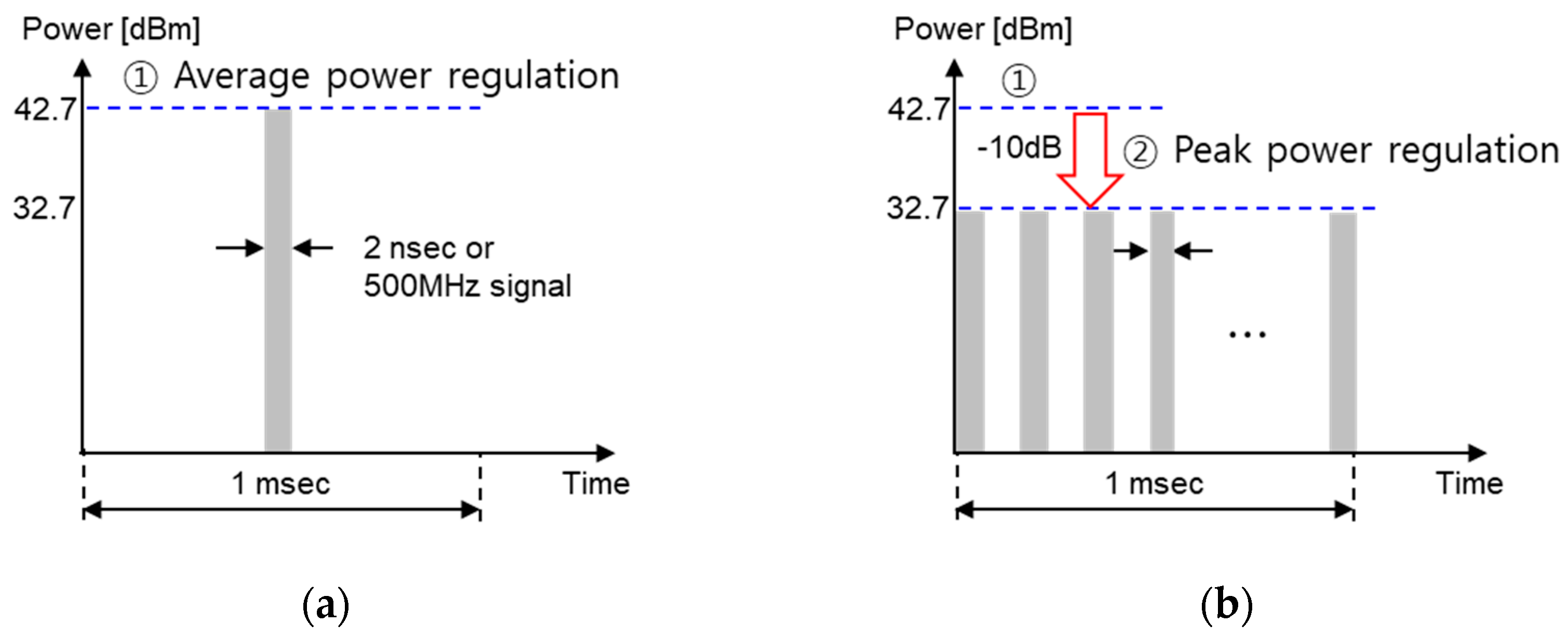
Figure 2.
Pulse characteristics of UWB radar and HRP UWB communication: (a) In the case of UWB radar; (b) In the case of HRP UWB communication.
Figure 2.
Pulse characteristics of UWB radar and HRP UWB communication: (a) In the case of UWB radar; (b) In the case of HRP UWB communication.
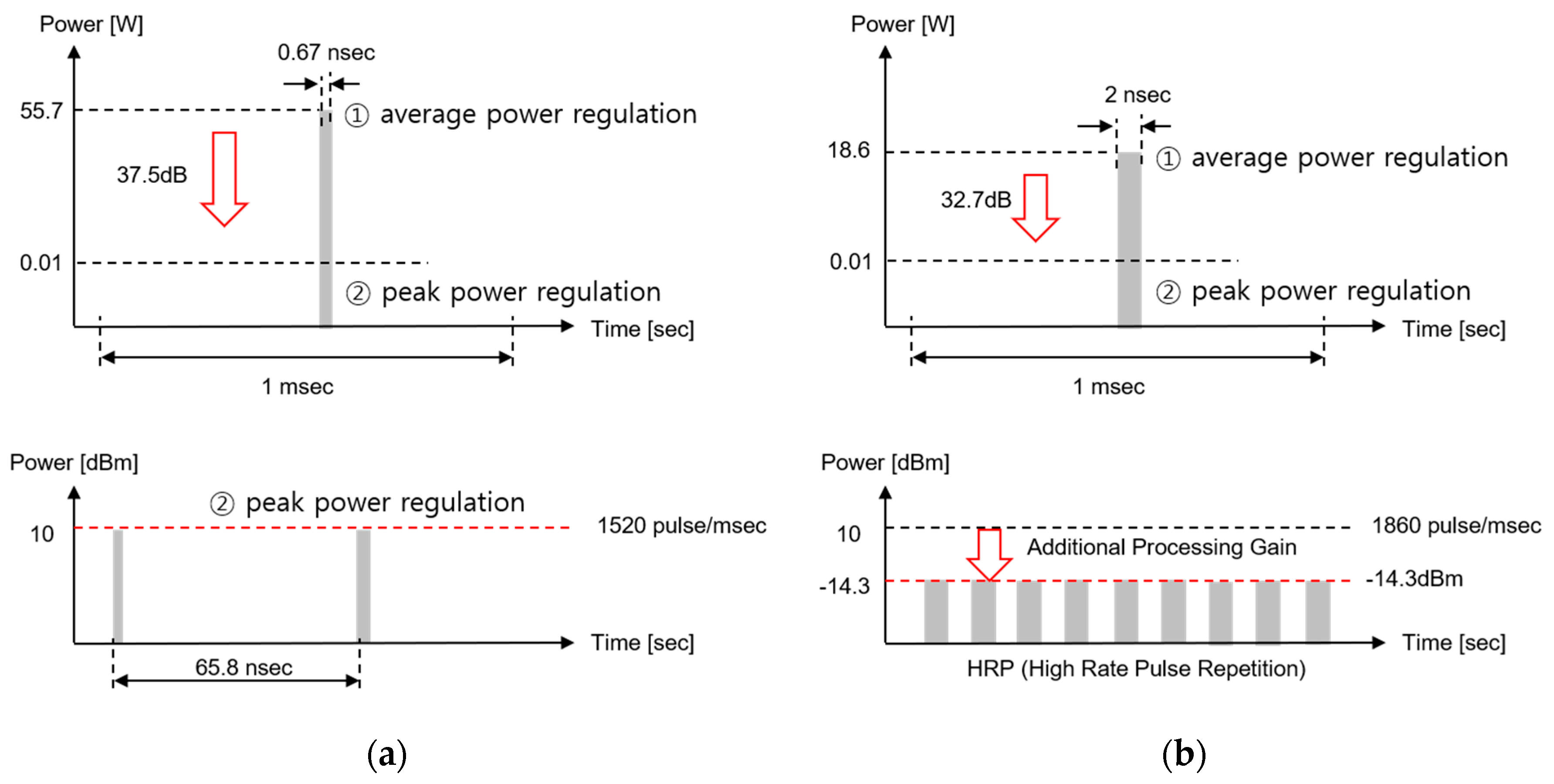
Figure 3.
Typical packet structure of IEEE 802.15.4z HRP UWB.
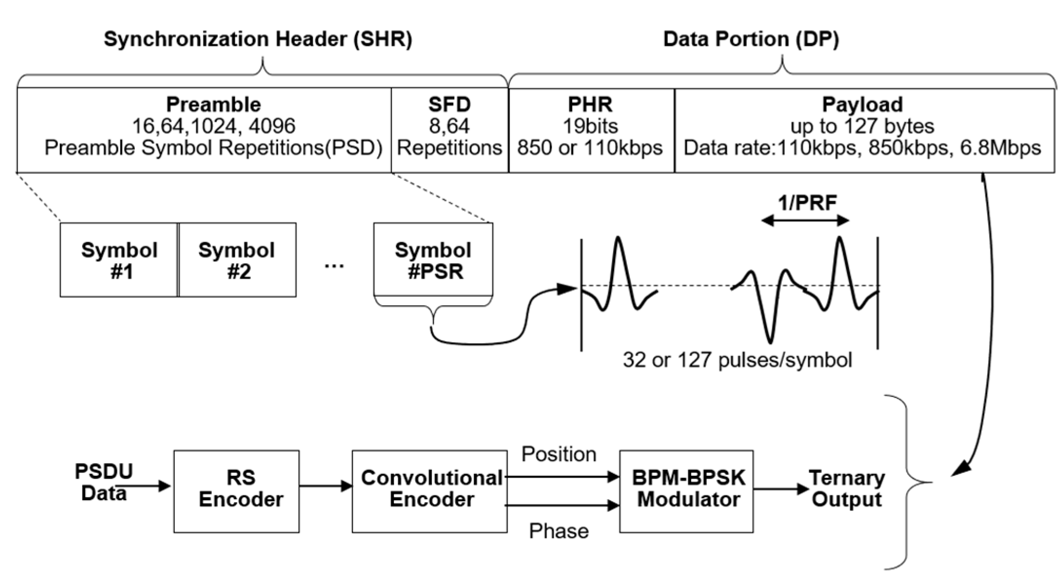
Figure 4.
Two way ranging: (a) Principle of UWB two way ranging; (b) Classification of HRP UWB two way ranging and related packets.
Figure 4.
Two way ranging: (a) Principle of UWB two way ranging; (b) Classification of HRP UWB two way ranging and related packets.
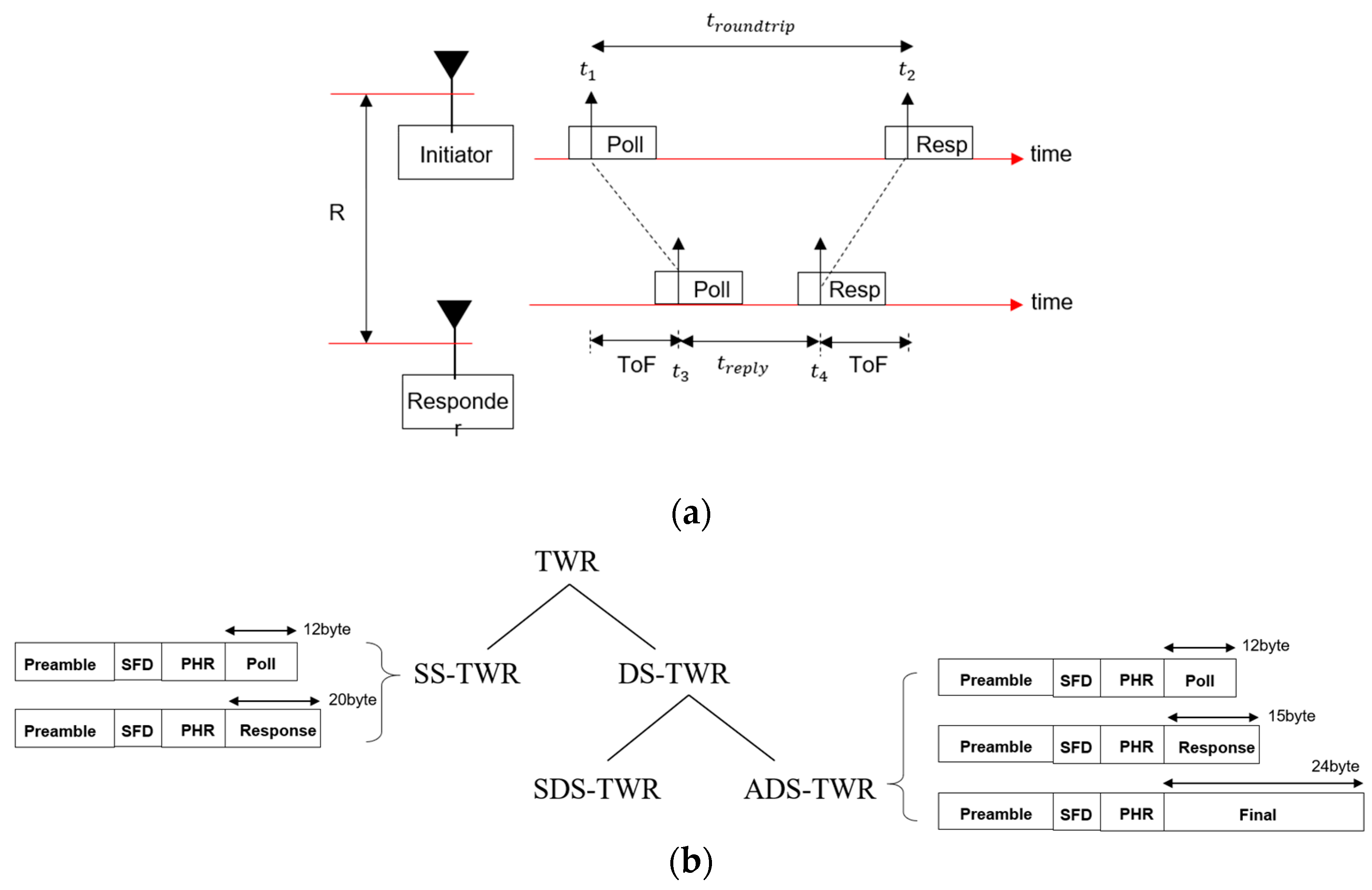
Figure 5.
Example of increased output power by Gating Gain.
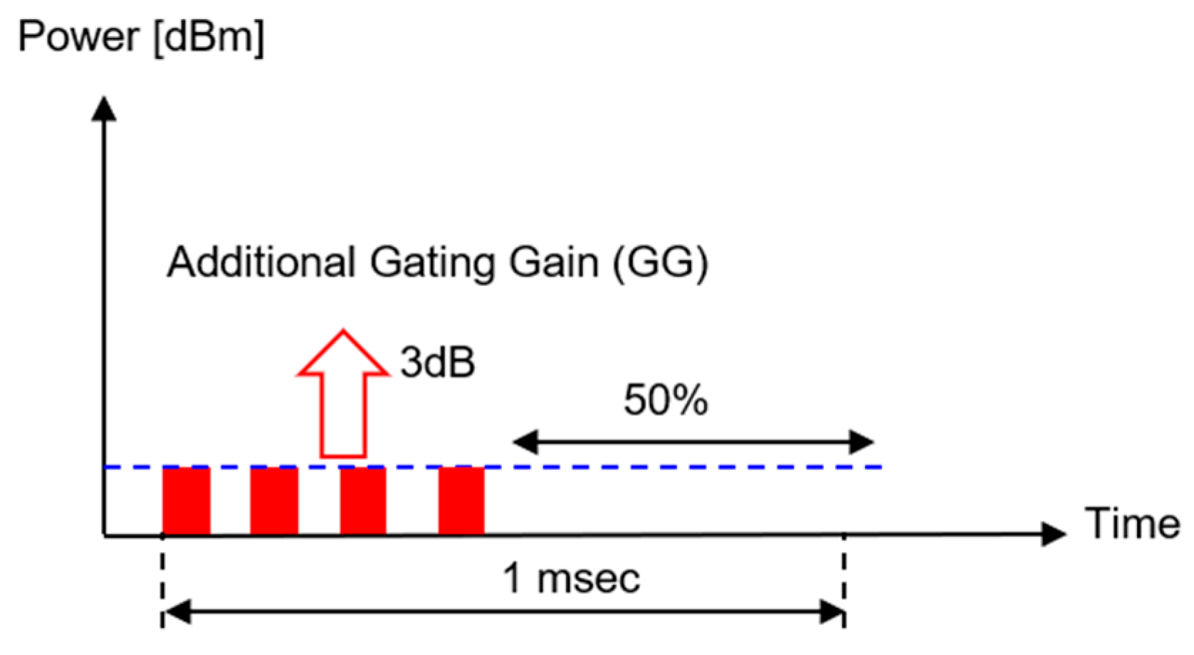
Figure 6.
Cramer-Rao Bound (CRB) for IEEE 802.15.4z HRP UWB ranging.
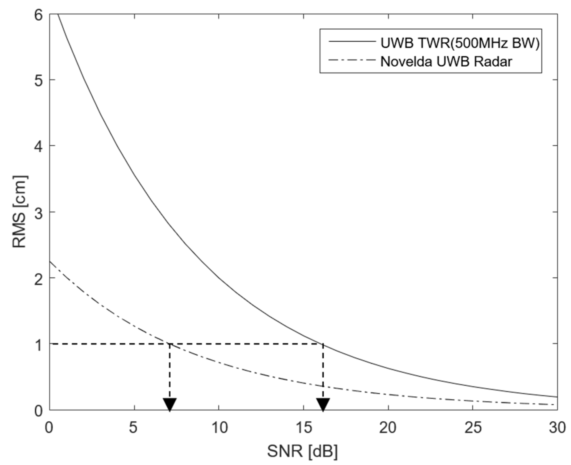
Figure 7.
Link budget of IEEE 802.15.4z HRP UWB: (a) In the case of preamble link; (b) In the case of 6.8Mbps data portion.
Figure 7.
Link budget of IEEE 802.15.4z HRP UWB: (a) In the case of preamble link; (b) In the case of 6.8Mbps data portion.
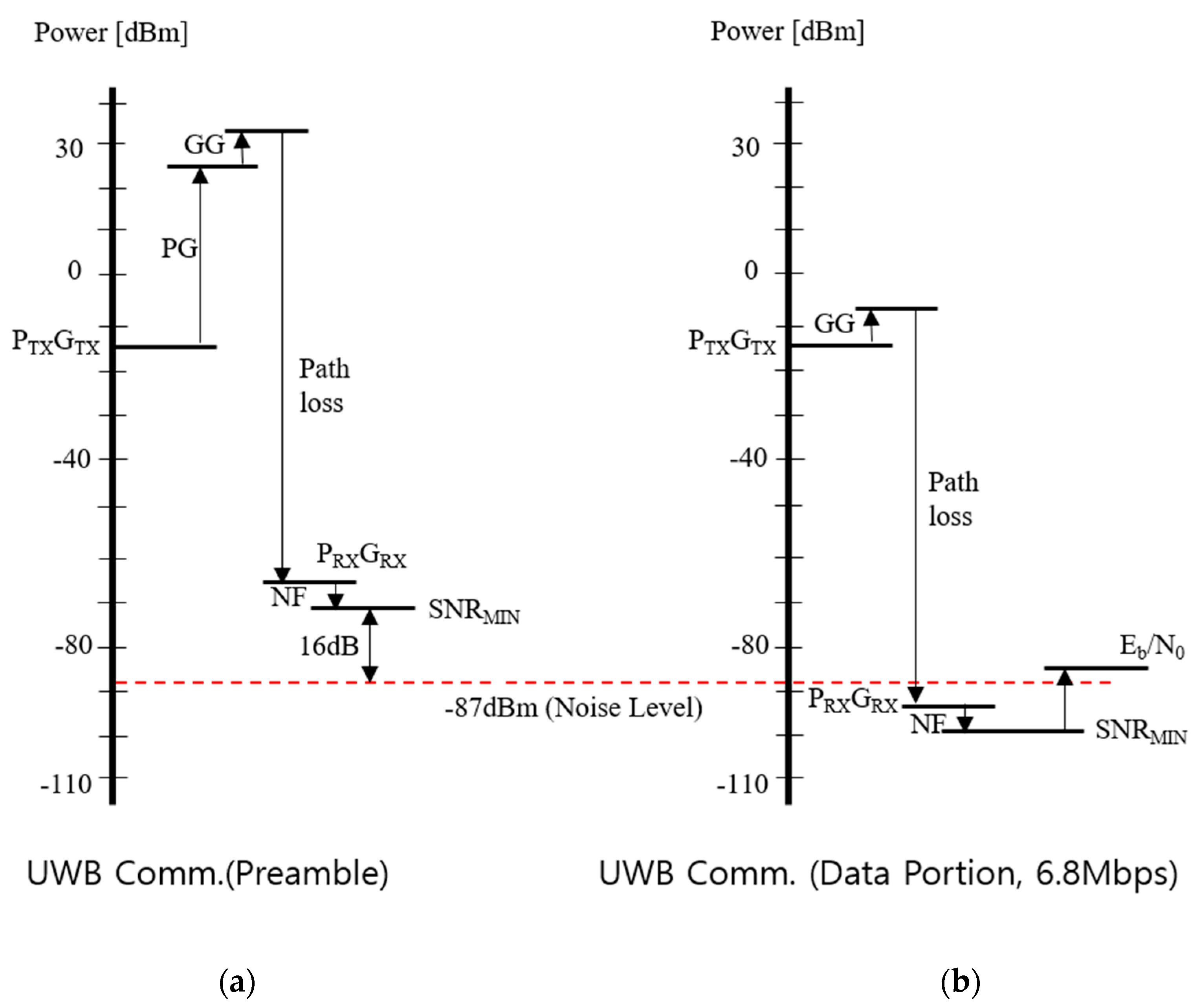
Figure 8.
Summary of ranging coverage extension concepts for IEEE 802.15.4z HRP UWB.
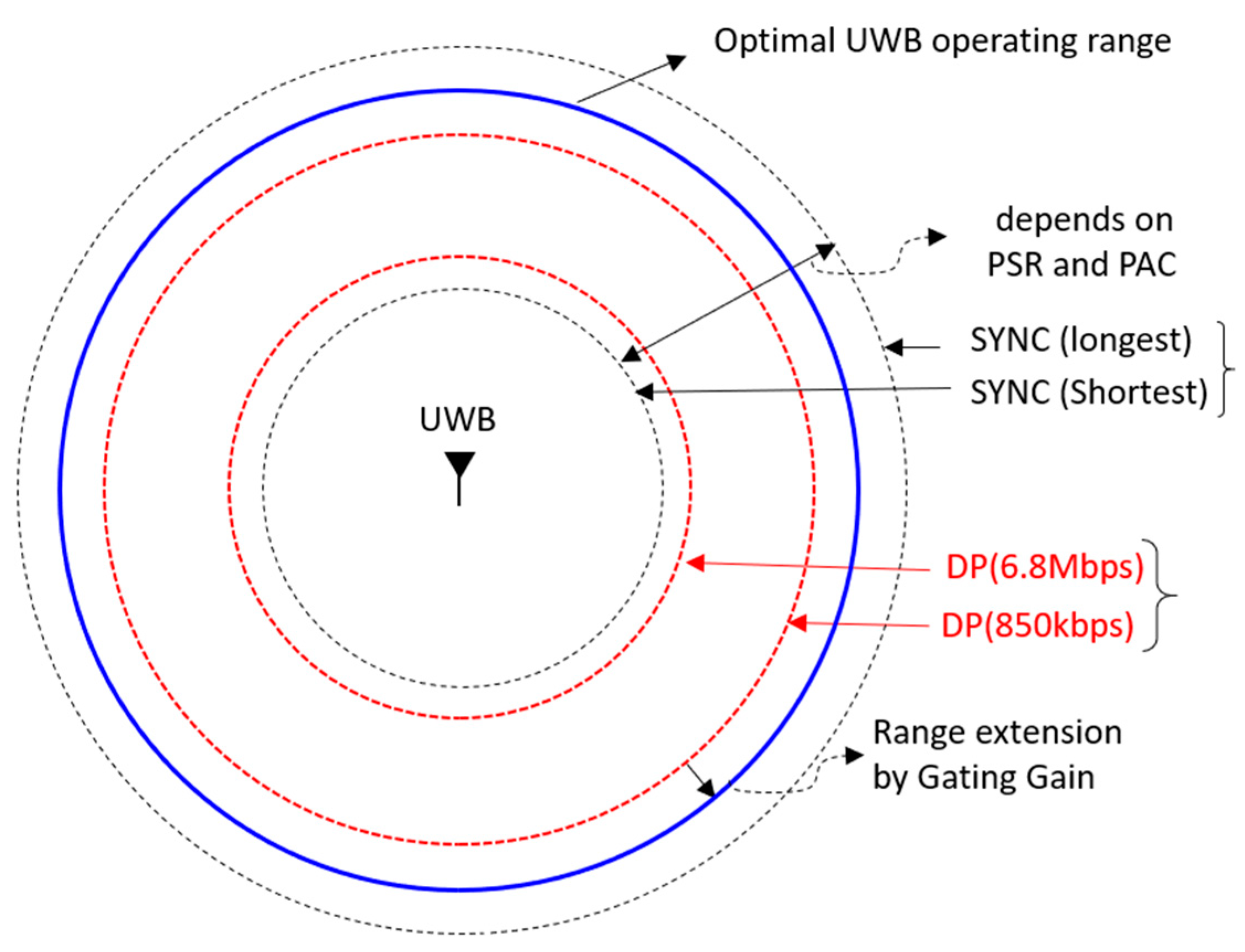
Figure 9.
Link experiment setup at 10m using DW3000 UWB module.
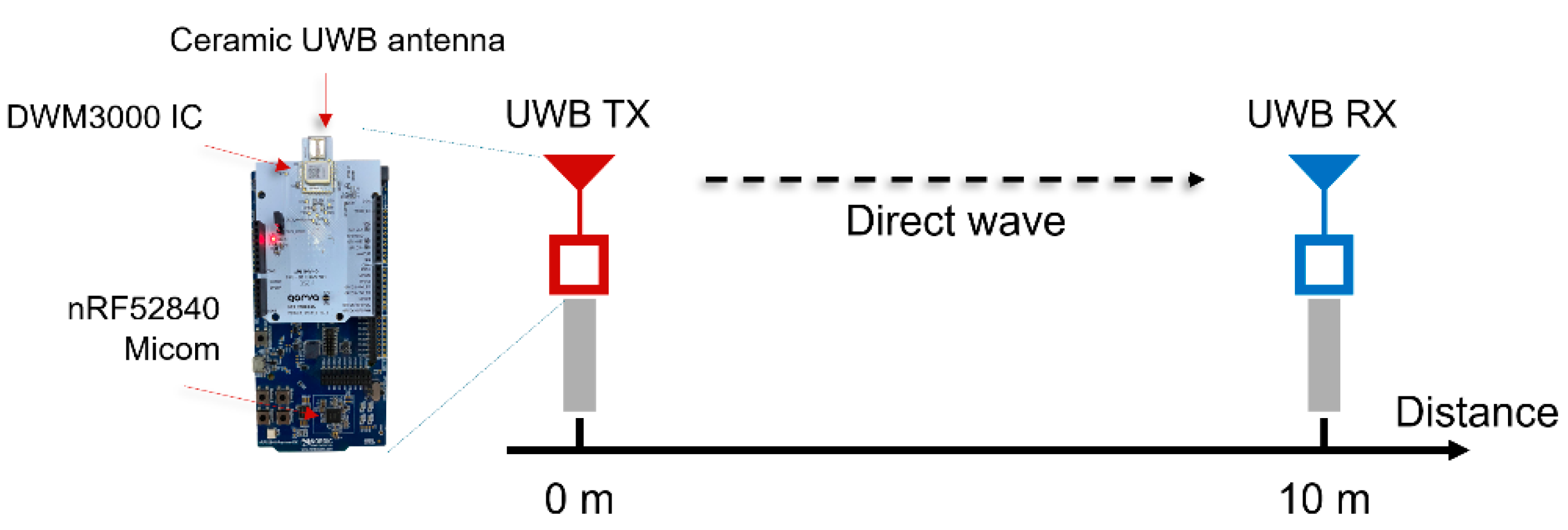
Figure 10.
Experiment results of HRP UWB at 10m using DW3000 UWB module: (a) low-speed (850 kbps) data transmission; (b) high-speed (6.8 Mbps) data transmission.
Figure 10.
Experiment results of HRP UWB at 10m using DW3000 UWB module: (a) low-speed (850 kbps) data transmission; (b) high-speed (6.8 Mbps) data transmission.
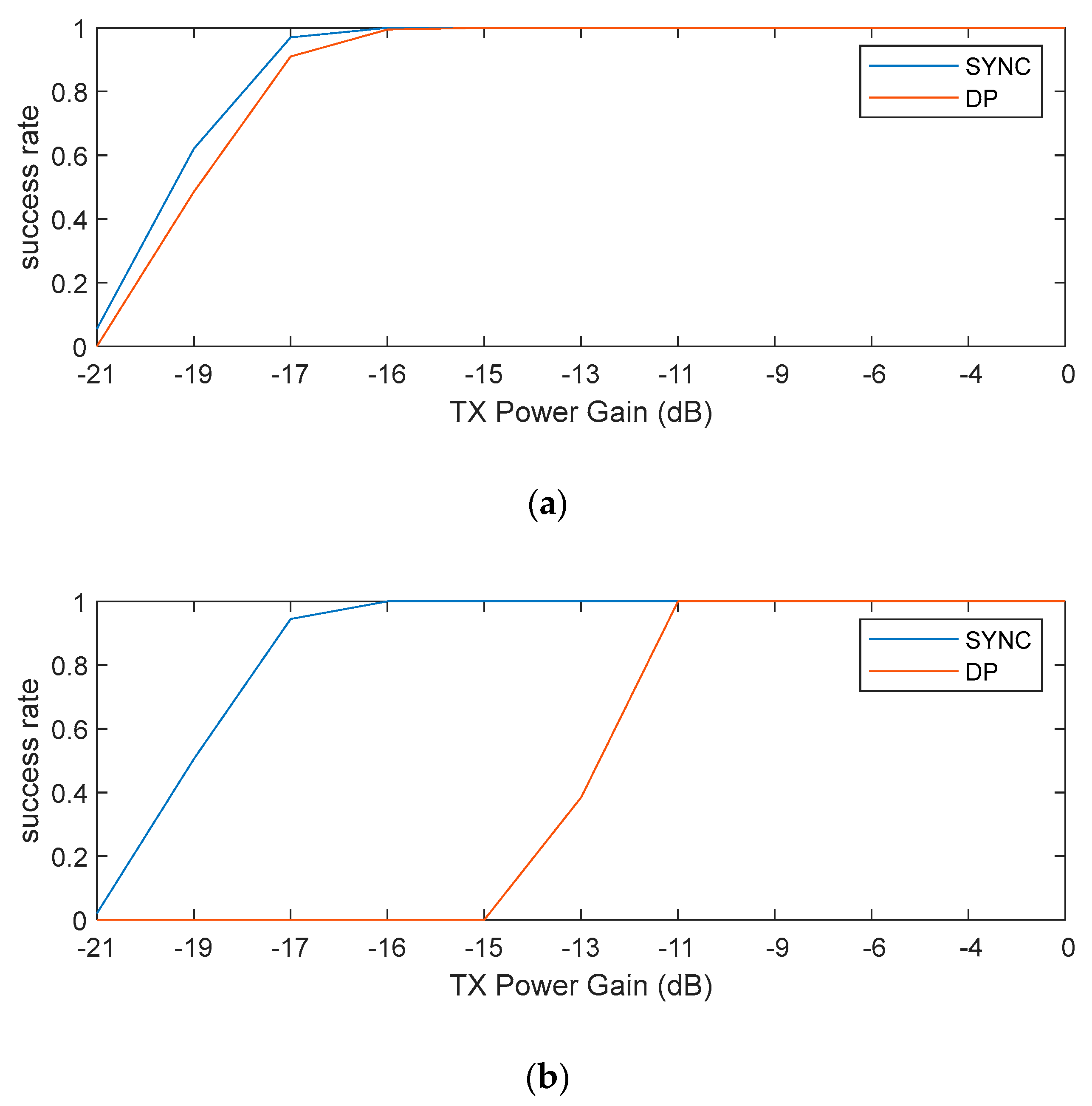
Figure 11.
Long ranging experiment setup
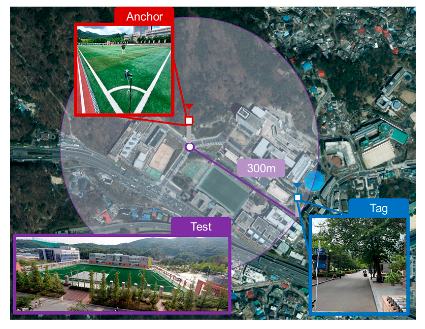
Figure 12.
Maximum measurable distance according to variations in PSR and PAC size based on a 90% success rate.
Figure 12.
Maximum measurable distance according to variations in PSR and PAC size based on a 90% success rate.
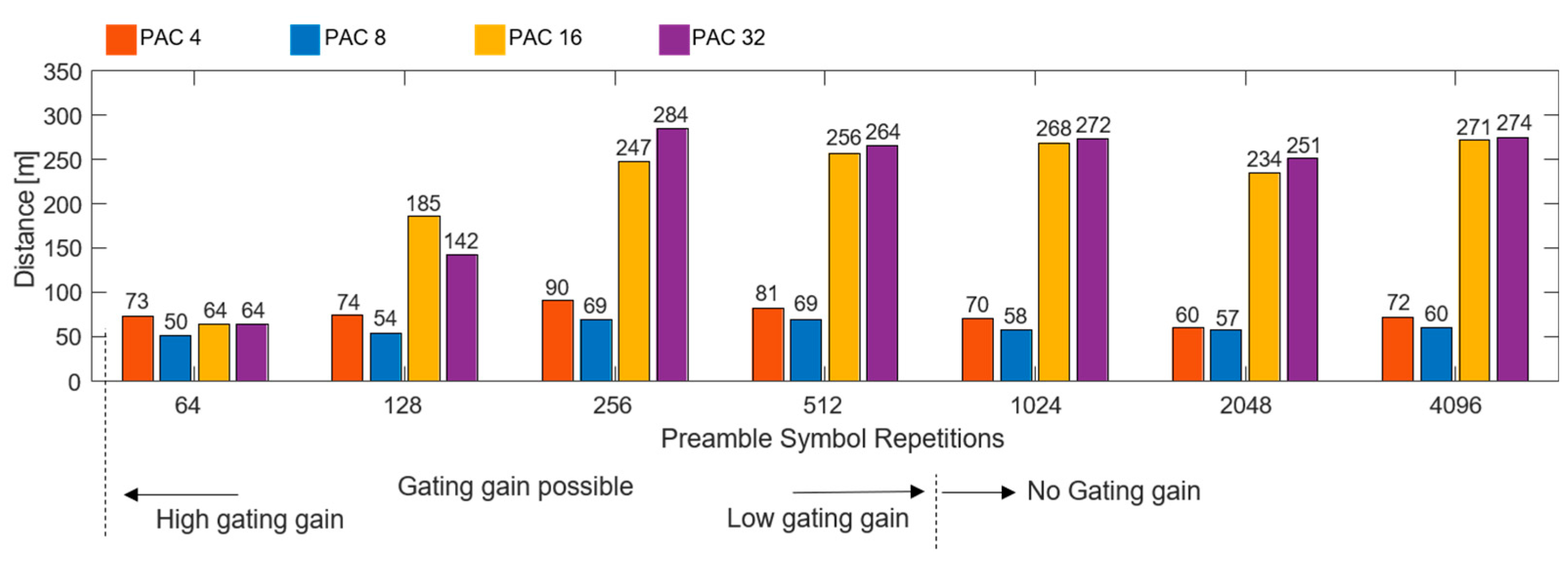

Table 1.
Key performance comparisons of previous UWB research results.
| Vendor | Chip/Module | Ranging Method | Frequency Range(GHz) | Operation Range(m) | Reference |
|---|---|---|---|---|---|
| Qorvo | DWM1000 | TWR, TDoA | 3.5-6.5 | ~50 | [18,19,20,21] |
| Qorvo | DW3000 | TWR, TDoA | 6.5, 8 | ~50 | [15,16,22] |
| Qorvo | DW3120 | TWR, TDoA, PDoA | 6.5, 8 | ~50 | [17,23] |
| NXP | SR150 | TWR, TDoA, PDoA | 6.24-8.24 | ~50 | [24] |
| NXP | SR040 | TWR, TDoA | 6.24-8.24 | ~50 | [25] |
| Spark | SR1010 | TWR | 3.1-6 | ~100 | [26] |
| Spark | SR1020 | TWR | 6-9.3 | ~100 | [26] |
| Qorvo | DW3000 | TWR | 6.5 | ~300 | This Work |
Table 2.
Local regulation for UWB worldwide.
| Local regulation | |
|---|---|
| Frequency | 3.1 GHz to 10.6GHz 1 |
| Average power | -41.3dBm/MHz@1msec① |
| Peak power | 0dBm/50MHz② |
| Bandwidth | More than 450MHz (1MHz RBW, 10dB Bandwidth) |
1 Frequency ranges vary slightly from country to country.
Table 3.
Link budget calculation of IEEE 802.15.4z HRP UWB.
| Preamble | Data Portion (850kbps) |
Data Portion (6.8Mbps) |
|
|---|---|---|---|
| Code length | 127 256 32 268.6 64 - - - - -41.3 499.2 7.98 6 36.1 0 -14.3 10.0 -106.7 92.6 50.5 42.2 |
- - - - 62.4 5.6 3/5 160 306.4 -41.3 499.2 7.98 6 - 0 -14.3 -21.6 -105.5 91.1 50.5 40.7 |
- - - - 62.4 5.6 3/5 160 100.9 -41.3 499.2 7.98 6 - 0 -14.3 -12.5 -96.5 82.1 50.5 31.7 |
| # of symbol PAC size Preamble length [usec] PRF [MHz] Coding gain [dB] Coded [dB] Payload [bits] Packet length PSD [dBm/MHz] Bandwidth [MHz]4Frequency [GHz] NF [dB] PG [dB] GG [dB] [dBm] [dB] S [dB] Path Loss [dB] [dB] Link Margin |
Table 4.
Configuration PHY settings in DW 3000 UWB module.
| PHY Setting | Values |
|---|---|
| RF channel | CH5 |
| PRF | 64MHz |
| PSR | 32, 64, 128, 256, 512, 1024, 2048, 4096 |
| PAC DP |
4.8, 16, 32 850kbps, 6.8Mbps |
Disclaimer/Publisher’s Note: The statements, opinions and data contained in all publications are solely those of the individual author(s) and contributor(s) and not of MDPI and/or the editor(s). MDPI and/or the editor(s) disclaim responsibility for any injury to people or property resulting from any ideas, methods, instructions or products referred to in the content. |
© 2025 by the authors. Licensee MDPI, Basel, Switzerland. This article is an open access article distributed under the terms and conditions of the Creative Commons Attribution (CC BY) license (http://creativecommons.org/licenses/by/4.0/).
Copyright: This open access article is published under a Creative Commons CC BY 4.0 license, which permit the free download, distribution, and reuse, provided that the author and preprint are cited in any reuse.


